EP4212839A1 - Thermomètre alimentaire fonctionnant sur batterie et ??procédé de fabrication - Google Patents
Thermomètre alimentaire fonctionnant sur batterie et ??procédé de fabrication Download PDFInfo
- Publication number
- EP4212839A1 EP4212839A1 EP22151484.7A EP22151484A EP4212839A1 EP 4212839 A1 EP4212839 A1 EP 4212839A1 EP 22151484 A EP22151484 A EP 22151484A EP 4212839 A1 EP4212839 A1 EP 4212839A1
- Authority
- EP
- European Patent Office
- Prior art keywords
- battery
- food
- housing
- phase change
- heat
- Prior art date
- Legal status (The legal status is an assumption and is not a legal conclusion. Google has not performed a legal analysis and makes no representation as to the accuracy of the status listed.)
- Granted
Links
Images

Classifications
-
- G—PHYSICS
- G01—MEASURING; TESTING
- G01K—MEASURING TEMPERATURE; MEASURING QUANTITY OF HEAT; THERMALLY-SENSITIVE ELEMENTS NOT OTHERWISE PROVIDED FOR
- G01K13/00—Thermometers specially adapted for specific purposes
-
- G—PHYSICS
- G01—MEASURING; TESTING
- G01K—MEASURING TEMPERATURE; MEASURING QUANTITY OF HEAT; THERMALLY-SENSITIVE ELEMENTS NOT OTHERWISE PROVIDED FOR
- G01K1/00—Details of thermometers not specially adapted for particular types of thermometer
- G01K1/02—Means for indicating or recording specially adapted for thermometers
- G01K1/024—Means for indicating or recording specially adapted for thermometers for remote indication
-
- G—PHYSICS
- G01—MEASURING; TESTING
- G01K—MEASURING TEMPERATURE; MEASURING QUANTITY OF HEAT; THERMALLY-SENSITIVE ELEMENTS NOT OTHERWISE PROVIDED FOR
- G01K1/00—Details of thermometers not specially adapted for particular types of thermometer
- G01K1/08—Protective devices, e.g. casings
-
- H—ELECTRICITY
- H01—ELECTRIC ELEMENTS
- H01M—PROCESSES OR MEANS, e.g. BATTERIES, FOR THE DIRECT CONVERSION OF CHEMICAL ENERGY INTO ELECTRICAL ENERGY
- H01M10/00—Secondary cells; Manufacture thereof
- H01M10/60—Heating or cooling; Temperature control
- H01M10/65—Means for temperature control structurally associated with the cells
- H01M10/658—Means for temperature control structurally associated with the cells by thermal insulation or shielding
-
- H—ELECTRICITY
- H01—ELECTRIC ELEMENTS
- H01M—PROCESSES OR MEANS, e.g. BATTERIES, FOR THE DIRECT CONVERSION OF CHEMICAL ENERGY INTO ELECTRICAL ENERGY
- H01M50/00—Constructional details or processes of manufacture of the non-active parts of electrochemical cells other than fuel cells, e.g. hybrid cells
- H01M50/20—Mountings; Secondary casings or frames; Racks, modules or packs; Suspension devices; Shock absorbers; Transport or carrying devices; Holders
- H01M50/218—Mountings; Secondary casings or frames; Racks, modules or packs; Suspension devices; Shock absorbers; Transport or carrying devices; Holders characterised by the material
- H01M50/22—Mountings; Secondary casings or frames; Racks, modules or packs; Suspension devices; Shock absorbers; Transport or carrying devices; Holders characterised by the material of the casings or racks
-
- G—PHYSICS
- G01—MEASURING; TESTING
- G01K—MEASURING TEMPERATURE; MEASURING QUANTITY OF HEAT; THERMALLY-SENSITIVE ELEMENTS NOT OTHERWISE PROVIDED FOR
- G01K2207/00—Application of thermometers in household appliances
- G01K2207/02—Application of thermometers in household appliances for measuring food temperature
- G01K2207/06—Application of thermometers in household appliances for measuring food temperature for preparation purposes
Definitions
- the invention relates to a food probe with a battery.
- the invention also relates to a method for manufacturing a food probe.
- a food thermometer is a temperature measuring device which is intended and suitable for measuring temperatures in a food or foodstuff during its preparation.
- a food thermometer can therefore measure temperatures that can occur when preparing a meal. Temperatures that deviate significantly from this cannot be measured.
- a food thermometer is up to the environmental conditions that can arise during the preparation of a meal.
- temperatures of less than 200°C are reached during the preparation of a dish.
- temperatures of 350°C can also be reached, for example for baking a pizza.
- Temperatures of more than 350°C are generally not exceeded.
- a food thermometer within the meaning of the present invention is therefore set up in such a way that temperatures above 400° C., preferably above 300° C., particularly preferably above 250° C., can no longer be measured.
- the food thermometer is set up so that it can be used in a conventional oven, i.e. at temperatures of up to 250°C or 220°C.
- a food thermometer within the meaning of the present invention is not designed in such a way that very low temperatures can be measured with it, for example temperatures well below minus temperatures, such as are reached in common household chest freezers or freezers.
- a food thermometer within the meaning of the present invention is therefore not designed in such a way that it can measure temperatures below -70°C.
- a food thermometer within the meaning of the present invention is designed in such a way that it can no longer measure temperatures below -50° C., because food is usually prepared with the addition of heat and very low temperatures are only used to freeze food.
- a food probe according to the present invention can withstand a steam atmosphere.
- a food thermometer is therefore always encapsulated waterproof.
- a food thermometer within the meaning of the present invention Resistant to common food ingredients such as lemon acid or vinegar.
- a food probe according to the present invention is intended and suitable for being inserted into food to be cooked in order to be able to measure a temperature inside the food to be cooked.
- a food thermometer can have an elongated measuring sensor with a pointed or at least a very thin end in order to be able to pierce the measuring sensor into relatively solid food such as meat.
- the probe includes a sensor with which a temperature can be measured.
- a food probe may have a handle that is not designed and adapted to be inserted into the food.
- the handle part can be gripped by a user in order to be able to pull the food probe out of food or food again.
- the handle part can also include a sensor with which a temperature can be measured. The ambient temperature outside of a food or meal can then also be measured.
- a food probe according to the present invention requires electricity to operate.
- the food probe therefore includes a battery, i.e. a storage device for electrical energy.
- the electrical current required for the operation of the food probe can be made available through the memory.
- the battery is basically a rechargeable battery.
- a battery is a temperature-sensitive component which, for safety reasons, must therefore be well protected from excessive heat.
- a food thermometer that is inserted into the food to be cooked, the area inside the food remains comparatively cool the longest. In a heated food preparation room, food acts like a thermal insulator. It is therefore advantageous to place the battery in this area.
- the area that is pierced into the food must be as thin as possible in order to be able to pierce the food probe into the food without great effort. It is therefore necessary to ensure that the battery has a particularly slim design if it is to be arranged in the area that is to be inserted into the food to be cooked.
- the aim of the present invention is to provide a food probe that is particularly well suited to the aforementioned requirements.
- a food probe has the features of claim 1.
- the secondary claim relates to a method for producing the food probe.
- the dependent claims relate to advantageous configurations.
- a food thermometer that includes a housing with a pointed end.
- the pointed end is intended and suitable for measuring a temperature inside an item to be cooked.
- a battery is located inside the housing.
- the battery is located at the pointed end of the food probe. The distance between the extreme end of the tip and the battery is therefore small and is, for example, no more than 2 cm, preferably no more than 1 cm.
- the battery is encased in thermal insulation that sits between the case and the battery. The battery is at least partially covered by the thermal insulation.
- a battery is a component that is manufactured separately from other food probe components.
- a battery basically includes a housing.
- the housing can be made of metal. Within the housing there may be materials that allow electrical energy to be stored electrochemically. There are two electrical conductors.
- the electrical conductors can be passed through an inner wall inside the housing of the battery.
- the battery can be a commercially available battery, which is therefore commercially available independently and independently of a food probe. In particular, the battery is elongated in order to be able to be conveniently accommodated at the top.
- the thermal insulation wraps around the battery and therefore then runs around the battery.
- the thermal insulation can then be shaped like a tube.
- the battery is preferably located completely within the thermal insulation, so that the end faces of the battery are also covered by the thermal insulation.
- the thermal insulation only partially covers the battery.
- the thermal insulation can be grid-like and therefore only partially cover the battery.
- the thermal insulation could consist of several elements that have been glued onto the battery, for example. If there is a gap between the elements, the thermal insulation only partially covers the battery.
- the elements can be different. There may be one or more first elements comprising a thermally insulating gas or a thermally insulating vacuum and thereby thermally isolating.
- One or more second elements may be present be that include a phase change material and thereby thermally insulate. If a battery is only partially covered, the battery will still be covered for the most part. Basically, at least 80% of the surface area of the battery is covered by the thermal insulation, preferably at least 90%. Thermal insulation that completely covers the surface of the battery, i.e. 100%, is preferable.
- Thermal insulation within the meaning of the invention is a material that is better able to protect against heat than the material adjacent to the thermal insulation.
- the thermal conductivity of the thermal insulation can, for example, be lower than the thermal conductivity of the materials adjoining it.
- Adjacent one or more materials may be metal.
- Adjacent one or more materials may be stainless steel.
- the housing of the food probe and/or the housing of the battery can be made of metal, such as stainless steel. The metal housing of the food probe can then adjoin the heat-insulating material on one side and/or the metal housing of the battery on the other side.
- Thermal insulation is not required to protect against such high temperatures. Therefore, thermal insulation is not provided for food thermometers, at least when the battery is placed at a tip of a food thermometer.
- the placement of a battery in the tip of a food probe protects against heat because food acts as a thermal insulator when the tip is inserted into the food.
- the thermometer must be thin at the tip in order to be able to pierce food without leaving excessively large holes in the food. Additional thermal insulation is therefore unfavorable because it increases the diameter of the food probe in the area of the tip.
- a battery is subject to signs of aging. With a food probe, care must be taken to ensure that a battery in a food probe can provide sufficient electrical energy to operate the food probe for several years. Even after several years, there must still be a sufficient minimum capacity so that the food probe can keep temperatures for a sufficiently long time during the preparation of can measure food. Otherwise, the food probe could no longer be used after a short time.
- the present invention is based on the finding that signs of aging in a battery can be greatly reduced if the battery of a food probe is not only arranged at the tip of the food probe, but is also protected by a heat-insulating layer. This makes it possible to use a battery with a relatively low capacity, which is built comparatively slim and small. Thus, in spite of the heat insulation, it can be achieved to be able to build the portion at the tip of a food probe thin. This also makes it possible to use smaller batteries, even if they age in a particularly temperature-sensitive manner.
- a lithium-ion battery can be used as the battery, or preferably a battery with a solid as the electrolyte.
- a battery with a ceramic electrolyte is also preferable for safety reasons.
- a supercapacitor can be provided as the battery, for example for safety reasons, among other things.
- the thermal insulation can be provided by a vacuum or by a good thermally insulating gas such as argon or krypton. There is then basically no other component of the food probe between the extreme end of the tip and the battery. There may be a temperature sensor abutting an inner wall of the tip, which may be powered by battery power. In this case, the only thing left between the very end of the tip and the battery is the temperature sensor.
- thermometer Inside the thermometer, in the case of vacuum or a heat-insulating gas, there is an inner wall that airtightly separates the space at the tip from the rest of the interior of the food thermometer.
- the battery is then arranged in the interior at the tip.
- Thermal insulation realized by a gas or a vacuum is advantageously insensitive to heat. In addition, there are no destructive thermal stresses due to temperature changes.
- the inner wall can be made of metal and can be glued to the housing, for example.
- the inner wall can be made of a plastic or resin. Plastic or resin are then basically selected so that these temperatures of at least 200 ° C or 220°C and thus cannot liquefy at 200°C or 220°C, for example.
- the thermal insulation can be formed by a phase change material.
- the phase change material may be housed with the battery in a closed space located at and/or within the tip.
- the phase change material can then be a liquid that is vaporized by the supply of heat and thus changes its phase.
- the phase change material can be in the form of a paste.
- the thermal insulation can be a combination of phase change material and a vacuum, or a combination of phase change material and a thermally insulating gas. The thermal insulation can thus be further improved. The space required for this can be kept small.
- the heat storage capacity of the phase change material is preferably as large as possible in order to be able to achieve a sufficiently large cooling effect for a long time.
- the phase change temperature at which the phase change takes place is below the maximum possible operating temperature of the food probe, since otherwise no phase change can take place.
- the phase change temperature is basically selected so that it is below the maximum temperature to which the battery should be exposed during discharging.
- the phase change temperature is preferably selected in such a way that it is lower than the maximum charging temperature of the battery in order to be able to charge the battery particularly quickly. Longer loading times can thus be advantageously avoided.
- the phase change temperature should therefore not be more than 70°C, preferably not more than 60°C.
- the phase change temperature is also selected so that it is above normal storage temperatures. The phase change temperature is therefore always above normal room temperatures.
- the phase change temperature should be at least 30°C, preferably at least 40°C.
- the phase change temperature at which the phase changes should be between 40°C and 53°C for the reasons mentioned above.
- the phase change material is preferably at a distance from the housing of the food probe. There then remains, for example, an air-filled gap between the phase change material and the housing. The gap is present at least when the temperature of the phase change material is below the temperature lies at which the change of phase takes place. This further improves battery protection from excessive heat. Disadvantageous thermal stresses are also avoided.
- the gap can be filled with a heat insulating gas.
- a vacuum can be present in the gap in order to provide further improved thermal insulation.
- the thermal insulation can be formed particularly effectively by such a combination of phase change material and vacuum or by a combination of phase change material and thermally insulating gas such as argon or krypton. The installation space required for this can still be slim.
- the phase change material is preferably shape-stabilized. This can ensure that there is a distance between the housing of the food probe and the phase change material at least when the temperature of the phase change material is below the temperature at which the phase change takes place.
- the thermal insulation can be formed by a composite material that includes the phase change material.
- the phase change material can thus be dimensionally stabilized.
- the phase change material can be encapsulated and thereby dimensionally stabilized.
- the phase change material can be macroencapsulated or microencapsulated.
- the phase change material can be encased by a film, for example.
- the foil may be stretchable to accommodate changes in volume of the phase change material.
- the film can be made of plastic.
- the heat insulating material may have been adhered to the battery.
- the battery may have been pushed into an enclosure made of heat-insulating material.
- the envelope may have been closed with a lid. Following this, the battery and thermal insulation may have been placed in the housing of the food probe.
- the capacity of the battery should be at least 100 ⁇ Ah, preferably at least 500 ⁇ Ah, in order to be able to achieve sufficiently long operating times for the food probe for the preparation of food.
- the capacity of the battery should not be more than 3 mAh, preferably not more than 2 mAh, in order to be able to keep the diameter of the tip of the food probe small.
- the housing of the food probe can consist entirely or at least predominantly of metal, preferably stainless steel.
- the housing can therefore be thermally conductive enough to be able to measure temperatures quickly.
- the housing can thus cope well with the thermal, chemical and mechanical requirements.
- the box in which the food probe can be stored in a thermally protected manner. A substantially constant storage temperature can thus be ensured.
- the box can be designed in such a way that it can serve as a charger for the battery of the food probe.
- heat-insulating material can be placed in a case having a pointed end.
- the thermally insulating material can be heated, for example to a temperature of at least 40°C, 60°C or 80°C.
- the battery can then be pushed into the heated thermal insulating material. If the heat-insulating material is subsequently cooled, a gap may form between the heat-insulating material and the housing.
- the battery can be held in a desired position within the housing by electrical conductors connected to the battery.
- the electrical conductors can be passed through an inner wall to fix the position of the electrical conductors within the food probe. The inner wall can thus help to hold the battery.
- the thermally insulating material may include a phase change material.
- the heat-insulating material to be heated for the production can be a granulate, which comprises a phase-change material.
- phase change material is particularly preferable because it is also able to protect the battery particularly well from excessively low temperatures of, for example, less than 0°C. If temperatures of, for example, less than 10°C or less than 0°C are to be measured with the food thermometer, the food thermometer is preferably brought to a temperature above the phase change temperature before the measurement until the phase change material at least predominantly, preferably completely, has lost its phase changed. If a low temperature is then measured, the phase change material protects the battery particularly well from the cold.
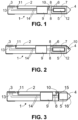
- the figure 1 shows a food thermometer 1.
- the food thermometer 1 comprises a pin-shaped housing part 2 and a cap 3.
- the pin-shaped housing part 2 is a tube which is sealed gas-tight at one end by a tip 4.
- the pin-shaped housing part 2 can be made of metal, such as stainless steel.
- the cap 3 can be screwed and/or glued to the pin-shaped housing part 2 .
- the cap 3 can be made of plastic to be used as a heat-protective handle.
- a battery 5 is located at the tip 4.
- the battery 5 is located within a double-walled housing 6.
- the space 7 between the two walls of the double-walled housing 6 can be filled with gas, such as argon or krypton. Alternatively, a vacuum can prevail in the space 7 .
- a phase change material can be located in the gap 7 .
- the temperature at which the phase changes can be between 40°C and 53°C.
- the double-walled housing 6 can rest against the inner wall of the tip 4 at points or in the form of a ring and can thus be held at one end.
- Two electrical conductors 8 can connect the battery 5 to electronics 9 .
- the electronics 2 are basically outside of the double-walled housing 6.
- the two electrical conductors 8 are then passed through the double-walled housing 6.
- the other end of the double-walled housing 6 can be held with the aid of the electronics 9 and the electrical conductors 8 .
- a first temperature sensor 10 electrically connected to the electronics 9 can be attached to the inner wall of the pin-shaped housing part 2 adjacent to the double-walled housing 6 . With this first temperature sensor 10, the temperature prevailing in the food to be cooked can be measured if the food probe 1 in food has been inserted.
- a second temperature sensor 11 is located at the cap 3 and is also attached to the inner wall of the housing. The temperature prevailing in a cooking chamber can be measured with the second temperature sensor 11 .
- the heat storage capacity of temperature sensors 10 and 11 is as small as possible, so that temperature sensors 10 and 11 can react particularly quickly to temperature changes.
- the gap 12 helps protect the battery 5 from heating.
- a coil 13 can be present, for example, in the cap 3, via which the battery 5 can be charged inductively.
- the coil 13 can be connected to the electronics 9 via electrical conductors 14 .
- the electrical conductors 14 can be connected to electrical contacts that can be reached from the outside. Charging can then take place via the contacts.
- the electronics 9 can include a microcontroller with which the temperature sensors 10 and 11 can be evaluated. The charging of the battery 5 can be controlled by the microcontroller.
- the electronics 9 can include a radio unit via which the food probe can wirelessly exchange data with an external device.
- An external device which can be a food processor, for example, can thus receive measured temperatures and control a cooking process depending on the measured temperatures.
- the diameter of the conductors 8 is preferably small in comparison to other electrical conductors within the food probe 1, for example small in comparison to the electrical conductors 14. This prevents the battery 5 from heating up via the electrical conductors 8.
- the distance between the extreme end of the tip 4 and the battery can be less than 2 cm or 1 cm.
- the one in the figure 2 shown embodiment differs from that in FIG figure 1 shown embodiment by arranging the first temperature sensor 10 on an inner wall of the tip 4. Between the tip 4 and the battery 5 there is then the first temperature sensor 10, but no other components.
- the inner wall 15 separates a space 16 at the tip 4 from the rest of the interior of the food probe 1 in a gas-tight manner.
- the phase change material attached may be shape stabilized.
- the attached phase change material may have been glued on. Otherwise there can be a vacuum in the space 16 .
- the space 16 can be filled with a heat-insulating gas.
- the space 16 can also be completely filled with a material which comprises a phase change material or which is formed by the phase change material.
- phase change material 17 is attached to the battery 5 . This may have been done by filling an area at the tip 4 with phase change material 17 and heating it. After that, the battery was immersed in the phase change material 17 . The phase change material 17 has contracted as a result of cooling and has thus become detached from the pin-shaped housing part 2 . In order to facilitate detachment, a film separating the phase change material 17 from the pin-shaped housing part 2 at the tip 4 can be present.
- FIG 5 an embodiment is shown with a housing 18 in which the battery 5 is located.
- the battery 5 is at a distance from the walls of the housing 18 .
- the housing 18 can be gas-tight, so that a vacuum can prevail in the housing 18 .
- a thermally insulating gas or a phase change material may be housed in the housing 18 .
- the housing 18 preferably does not contact the pin-shaped housing part 2 in order to provide improved protection against heat. This is especially true when there is phase change material in housing 18 .
- the housing 18 can be in two parts and can be formed from a container and a lid.
Landscapes
- Physics & Mathematics (AREA)
- General Physics & Mathematics (AREA)
- Chemical & Material Sciences (AREA)
- Chemical Kinetics & Catalysis (AREA)
- Electrochemistry (AREA)
- General Chemical & Material Sciences (AREA)
- Engineering & Computer Science (AREA)
- Manufacturing & Machinery (AREA)
- Measuring Temperature Or Quantity Of Heat (AREA)
Priority Applications (4)
| Application Number | Priority Date | Filing Date | Title |
|---|---|---|---|
| EP22151484.7A EP4212839B1 (fr) | 2022-01-14 | 2022-01-14 | Thermomètre alimentaire fonctionnant sur batterie et ??procédé de fabrication |
| AU2022275506A AU2022275506B2 (en) | 2022-01-14 | 2022-11-25 | Battery-operated food thermometer and manufacturing method |
| US18/093,172 US20230228627A1 (en) | 2022-01-14 | 2023-01-04 | Battery-operated food thermometer and manufacturing method |
| CN202310055183.6A CN116448271A (zh) | 2022-01-14 | 2023-01-13 | 电池供电的食物温度计和制造方法 |
Applications Claiming Priority (1)
| Application Number | Priority Date | Filing Date | Title |
|---|---|---|---|
| EP22151484.7A EP4212839B1 (fr) | 2022-01-14 | 2022-01-14 | Thermomètre alimentaire fonctionnant sur batterie et ??procédé de fabrication |
Publications (2)
| Publication Number | Publication Date |
|---|---|
| EP4212839A1 true EP4212839A1 (fr) | 2023-07-19 |
| EP4212839B1 EP4212839B1 (fr) | 2026-04-22 |
Family
ID=80112459
Family Applications (1)
| Application Number | Title | Priority Date | Filing Date |
|---|---|---|---|
| EP22151484.7A Active EP4212839B1 (fr) | 2022-01-14 | 2022-01-14 | Thermomètre alimentaire fonctionnant sur batterie et ??procédé de fabrication |
Country Status (4)
| Country | Link |
|---|---|
| US (1) | US20230228627A1 (fr) |
| EP (1) | EP4212839B1 (fr) |
| CN (1) | CN116448271A (fr) |
| AU (1) | AU2022275506B2 (fr) |
Cited By (1)
| Publication number | Priority date | Publication date | Assignee | Title |
|---|---|---|---|---|
| CN117387795A (zh) * | 2023-10-23 | 2024-01-12 | 武汉特普生传感技术有限公司 | 食物温度探针 |
Families Citing this family (2)
| Publication number | Priority date | Publication date | Assignee | Title |
|---|---|---|---|---|
| CN221725395U (zh) * | 2023-09-28 | 2024-09-17 | 深圳市英博伟业科技有限公司 | 一种探针 |
| USD1101580S1 (en) | 2024-01-31 | 2025-11-11 | Sharkninja Operating Llc | Temperature probe holder |
Citations (4)
| Publication number | Priority date | Publication date | Assignee | Title |
|---|---|---|---|---|
| DE102004047756A1 (de) * | 2004-09-30 | 2006-04-06 | BSH Bosch und Siemens Hausgeräte GmbH | Temperatursensorvorrichtung |
| WO2012119725A1 (fr) * | 2011-03-04 | 2012-09-13 | Tecpoint Gmbh | Dispositif de détection de la température intérieure d'un produit alimentaire |
| US20200129006A1 (en) * | 2017-06-01 | 2020-04-30 | Apption Labs Limited | Temperature sensing devices and wireless communication improvements for cooking appliances |
| EP3855142A1 (fr) * | 2020-01-27 | 2021-07-28 | Grandex International Corporation | Thermomètre étanche à l'eau pour la surveillance des températures d'aliments pendant un processus de cuisson |
Family Cites Families (4)
| Publication number | Priority date | Publication date | Assignee | Title |
|---|---|---|---|---|
| US7075442B2 (en) * | 2003-07-07 | 2006-07-11 | Mastrad Sa | Food temperature monitoring device |
| DK178659B1 (en) * | 2014-10-14 | 2016-10-17 | Nels Nielsen | Wireless cooking thermometer |
| CN209945571U (zh) * | 2019-05-29 | 2020-01-14 | 深圳市菲明格科技有限公司 | 一种烘培蒸烤无线高温探针 |
| CN113758597B (zh) * | 2021-09-02 | 2024-09-13 | 广东美的厨房电器制造有限公司 | 温度探针和烤箱组件 |
-
2022
- 2022-01-14 EP EP22151484.7A patent/EP4212839B1/fr active Active
- 2022-11-25 AU AU2022275506A patent/AU2022275506B2/en active Active
-
2023
- 2023-01-04 US US18/093,172 patent/US20230228627A1/en active Pending
- 2023-01-13 CN CN202310055183.6A patent/CN116448271A/zh active Pending
Patent Citations (4)
| Publication number | Priority date | Publication date | Assignee | Title |
|---|---|---|---|---|
| DE102004047756A1 (de) * | 2004-09-30 | 2006-04-06 | BSH Bosch und Siemens Hausgeräte GmbH | Temperatursensorvorrichtung |
| WO2012119725A1 (fr) * | 2011-03-04 | 2012-09-13 | Tecpoint Gmbh | Dispositif de détection de la température intérieure d'un produit alimentaire |
| US20200129006A1 (en) * | 2017-06-01 | 2020-04-30 | Apption Labs Limited | Temperature sensing devices and wireless communication improvements for cooking appliances |
| EP3855142A1 (fr) * | 2020-01-27 | 2021-07-28 | Grandex International Corporation | Thermomètre étanche à l'eau pour la surveillance des températures d'aliments pendant un processus de cuisson |
Cited By (1)
| Publication number | Priority date | Publication date | Assignee | Title |
|---|---|---|---|---|
| CN117387795A (zh) * | 2023-10-23 | 2024-01-12 | 武汉特普生传感技术有限公司 | 食物温度探针 |
Also Published As
| Publication number | Publication date |
|---|---|
| AU2022275506B2 (en) | 2024-08-15 |
| US20230228627A1 (en) | 2023-07-20 |
| EP4212839B1 (fr) | 2026-04-22 |
| CN116448271A (zh) | 2023-07-18 |
| AU2022275506A1 (en) | 2023-08-03 |
Similar Documents
| Publication | Publication Date | Title |
|---|---|---|
| EP4212839A1 (fr) | Thermomètre alimentaire fonctionnant sur batterie et ??procédé de fabrication | |
| Gummow et al. | Lithium-cobalt-nickel-oxide cathode materials prepared at 400 C for rechargeable lithium batteries | |
| Wang et al. | Characterization of thin‐film rechargeable lithium batteries with lithium cobalt oxide cathodes | |
| De Kock et al. | Defect spinels in the system Li2O. yMnO2 (y> 2.5): A neutron-diffraction study and electrochemical characterization of Li2Mn4O9 | |
| Hong et al. | Kinetic behavior of LiFeMgPO4 cathode material for Li-ion batteries | |
| AU672104B2 (en) | Preparation of silver vanadium oxide cathodes using Ag20 and V2O5 as starting materials | |
| Maleki et al. | Thermal properties of lithium‐ion battery and components | |
| Striebel et al. | Electrochemical behavior of LiMn2 O 4 and LiCoO2 thin films produced with pulsed laser deposition | |
| EP4158711B1 (fr) | Élément électrochimique | |
| CN102308425A (zh) | 石榴石型锂离子传导性氧化物和含有所述氧化物的全固态锂离子二次电池 | |
| DE69409499T2 (de) | Wässrige elektrochemische Herstellung von Interkalierverbindungen und ihre Verwendung in nichtwässrigen wiederaufladbare Batterien | |
| EP3650781A1 (fr) | Récipient pouvant être mis en température pourvu d'éléments d'isolation sous vide | |
| CH638343A5 (de) | Elektrische primaerzelle. | |
| EP0310982A2 (fr) | Procédé pour empêcher le surchauffage d'accumulateurs travaillant à haute température | |
| EP4198473A1 (fr) | Thermomètre alimentaire électrique rechargeable et dispositif de charge | |
| DE3046032A1 (de) | "thermische isolierung" | |
| James et al. | Lithium ion diffusion in the defect thiospinel LixCu0. 07Ti2S4 (0.1⩽ x⩽ 1.85) | |
| US4443525A (en) | High-temperature battery | |
| DE102015216014A1 (de) | Batteriepack | |
| Manickam | Lithium-free transition metal phosphate cathode for Li secondary batteries | |
| EP0158815B1 (fr) | Elément d'accumulateur électrochimique | |
| Garg et al. | Single crystal structure, electrical and electrochemical properties of the quaternary thiospinel: Ag2FeSn3S8 | |
| Ratnakumar et al. | Kinetics of intercalation of Lithium into NbSe3 and TiS2 cathodes | |
| KR20220073768A (ko) | 고체 상태 배터리용 양극의 전이금속 황화물 화합물의 용도 | |
| EP4459250A1 (fr) | Système thermométrique et conteneur pour un magasin de batterie thermométrique et utilisation |
Legal Events
| Date | Code | Title | Description |
|---|---|---|---|
| PUAI | Public reference made under article 153(3) epc to a published international application that has entered the european phase |
Free format text: ORIGINAL CODE: 0009012 |
|
| STAA | Information on the status of an ep patent application or granted ep patent |
Free format text: STATUS: THE APPLICATION HAS BEEN PUBLISHED |
|
| AK | Designated contracting states |
Kind code of ref document: A1 Designated state(s): AL AT BE BG CH CY CZ DE DK EE ES FI FR GB GR HR HU IE IS IT LI LT LU LV MC MK MT NL NO PL PT RO RS SE SI SK SM TR |
|
| STAA | Information on the status of an ep patent application or granted ep patent |
Free format text: STATUS: REQUEST FOR EXAMINATION WAS MADE |
|
| 17P | Request for examination filed |
Effective date: 20240110 |
|
| RBV | Designated contracting states (corrected) |
Designated state(s): AL AT BE BG CH CY CZ DE DK EE ES FI FR GB GR HR HU IE IS IT LI LT LU LV MC MK MT NL NO PL PT RO RS SE SI SK SM TR |
|
| GRAP | Despatch of communication of intention to grant a patent |
Free format text: ORIGINAL CODE: EPIDOSNIGR1 |
|
| STAA | Information on the status of an ep patent application or granted ep patent |
Free format text: STATUS: GRANT OF PATENT IS INTENDED |
|
| INTG | Intention to grant announced |
Effective date: 20260105 |
|
| RAP3 | Party data changed (applicant data changed or rights of an application transferred) |
Owner name: VORWERK & CO. INTERHOLDING GMBH |
|
| GRAS | Grant fee paid |
Free format text: ORIGINAL CODE: EPIDOSNIGR3 |
|
| GRAA | (expected) grant |
Free format text: ORIGINAL CODE: 0009210 |
|
| STAA | Information on the status of an ep patent application or granted ep patent |
Free format text: STATUS: THE PATENT HAS BEEN GRANTED |
|
| AK | Designated contracting states |
Kind code of ref document: B1 Designated state(s): AL AT BE BG CH CY CZ DE DK EE ES FI FR GB GR HR HU IE IS IT LI LT LU LV MC MK MT NL NO PL PT RO RS SE SI SK SM TR |
|
| REG | Reference to a national code |
Ref country code: CH Ref legal event code: F10 Free format text: ST27 STATUS EVENT CODE: U-0-0-F10-F00 (AS PROVIDED BY THE NATIONAL OFFICE) Effective date: 20260422 Ref country code: GB Ref legal event code: FG4D Free format text: NOT ENGLISH |