EP4213280A1 - Sekundärbatterie - Google Patents
Sekundärbatterie Download PDFInfo
- Publication number
- EP4213280A1 EP4213280A1 EP23151507.3A EP23151507A EP4213280A1 EP 4213280 A1 EP4213280 A1 EP 4213280A1 EP 23151507 A EP23151507 A EP 23151507A EP 4213280 A1 EP4213280 A1 EP 4213280A1
- Authority
- EP
- European Patent Office
- Prior art keywords
- electrode assembly
- retainer
- insulating sheet
- secondary battery
- electrode
- Prior art date
- Legal status (The legal status is an assumption and is not a legal conclusion. Google has not performed a legal analysis and makes no representation as to the accuracy of the status listed.)
- Granted
Links
Images


Classifications
-
- H—ELECTRICITY
- H01—ELECTRIC ELEMENTS
- H01M—PROCESSES OR MEANS, e.g. BATTERIES, FOR THE DIRECT CONVERSION OF CHEMICAL ENERGY INTO ELECTRICAL ENERGY
- H01M10/00—Secondary cells; Manufacture thereof
- H01M10/05—Accumulators with non-aqueous electrolyte
- H01M10/052—Li-accumulators
-
- H—ELECTRICITY
- H01—ELECTRIC ELEMENTS
- H01M—PROCESSES OR MEANS, e.g. BATTERIES, FOR THE DIRECT CONVERSION OF CHEMICAL ENERGY INTO ELECTRICAL ENERGY
- H01M10/00—Secondary cells; Manufacture thereof
- H01M10/60—Heating or cooling; Temperature control
- H01M10/65—Means for temperature control structurally associated with the cells
- H01M10/658—Means for temperature control structurally associated with the cells by thermal insulation or shielding
-
- H—ELECTRICITY
- H01—ELECTRIC ELEMENTS
- H01M—PROCESSES OR MEANS, e.g. BATTERIES, FOR THE DIRECT CONVERSION OF CHEMICAL ENERGY INTO ELECTRICAL ENERGY
- H01M50/00—Constructional details or processes of manufacture of the non-active parts of electrochemical cells other than fuel cells, e.g. hybrid cells
- H01M50/10—Primary casings; Jackets or wrappings
- H01M50/116—Primary casings; Jackets or wrappings characterised by the material
- H01M50/121—Organic material
-
- H—ELECTRICITY
- H01—ELECTRIC ELEMENTS
- H01M—PROCESSES OR MEANS, e.g. BATTERIES, FOR THE DIRECT CONVERSION OF CHEMICAL ENERGY INTO ELECTRICAL ENERGY
- H01M10/00—Secondary cells; Manufacture thereof
- H01M10/04—Construction or manufacture in general
- H01M10/0436—Small-sized flat cells or batteries for portable equipment
-
- H—ELECTRICITY
- H01—ELECTRIC ELEMENTS
- H01M—PROCESSES OR MEANS, e.g. BATTERIES, FOR THE DIRECT CONVERSION OF CHEMICAL ENERGY INTO ELECTRICAL ENERGY
- H01M10/00—Secondary cells; Manufacture thereof
- H01M10/05—Accumulators with non-aqueous electrolyte
- H01M10/058—Construction or manufacture
-
- H—ELECTRICITY
- H01—ELECTRIC ELEMENTS
- H01M—PROCESSES OR MEANS, e.g. BATTERIES, FOR THE DIRECT CONVERSION OF CHEMICAL ENERGY INTO ELECTRICAL ENERGY
- H01M10/00—Secondary cells; Manufacture thereof
- H01M10/06—Lead-acid accumulators
- H01M10/12—Construction or manufacture
- H01M10/14—Assembling a group of electrodes or separators
-
- H—ELECTRICITY
- H01—ELECTRIC ELEMENTS
- H01M—PROCESSES OR MEANS, e.g. BATTERIES, FOR THE DIRECT CONVERSION OF CHEMICAL ENERGY INTO ELECTRICAL ENERGY
- H01M4/00—Electrodes
- H01M4/02—Electrodes composed of, or comprising, active material
- H01M4/13—Electrodes for accumulators with non-aqueous electrolyte, e.g. for lithium-accumulators; Processes of manufacture thereof
-
- H—ELECTRICITY
- H01—ELECTRIC ELEMENTS
- H01M—PROCESSES OR MEANS, e.g. BATTERIES, FOR THE DIRECT CONVERSION OF CHEMICAL ENERGY INTO ELECTRICAL ENERGY
- H01M4/00—Electrodes
- H01M4/02—Electrodes composed of, or comprising, active material
- H01M4/64—Carriers or collectors
- H01M4/70—Carriers or collectors characterised by shape or form
-
- H—ELECTRICITY
- H01—ELECTRIC ELEMENTS
- H01M—PROCESSES OR MEANS, e.g. BATTERIES, FOR THE DIRECT CONVERSION OF CHEMICAL ENERGY INTO ELECTRICAL ENERGY
- H01M50/00—Constructional details or processes of manufacture of the non-active parts of electrochemical cells other than fuel cells, e.g. hybrid cells
- H01M50/10—Primary casings; Jackets or wrappings
- H01M50/102—Primary casings; Jackets or wrappings characterised by their shape or physical structure
- H01M50/103—Primary casings; Jackets or wrappings characterised by their shape or physical structure prismatic or rectangular
-
- H—ELECTRICITY
- H01—ELECTRIC ELEMENTS
- H01M—PROCESSES OR MEANS, e.g. BATTERIES, FOR THE DIRECT CONVERSION OF CHEMICAL ENERGY INTO ELECTRICAL ENERGY
- H01M50/00—Constructional details or processes of manufacture of the non-active parts of electrochemical cells other than fuel cells, e.g. hybrid cells
- H01M50/10—Primary casings; Jackets or wrappings
- H01M50/102—Primary casings; Jackets or wrappings characterised by their shape or physical structure
- H01M50/105—Pouches or flexible bags
-
- H—ELECTRICITY
- H01—ELECTRIC ELEMENTS
- H01M—PROCESSES OR MEANS, e.g. BATTERIES, FOR THE DIRECT CONVERSION OF CHEMICAL ENERGY INTO ELECTRICAL ENERGY
- H01M50/00—Constructional details or processes of manufacture of the non-active parts of electrochemical cells other than fuel cells, e.g. hybrid cells
- H01M50/10—Primary casings; Jackets or wrappings
- H01M50/147—Lids or covers
- H01M50/148—Lids or covers characterised by their shape
- H01M50/15—Lids or covers characterised by their shape for prismatic or rectangular cells
-
- H—ELECTRICITY
- H01—ELECTRIC ELEMENTS
- H01M—PROCESSES OR MEANS, e.g. BATTERIES, FOR THE DIRECT CONVERSION OF CHEMICAL ENERGY INTO ELECTRICAL ENERGY
- H01M50/00—Constructional details or processes of manufacture of the non-active parts of electrochemical cells other than fuel cells, e.g. hybrid cells
- H01M50/10—Primary casings; Jackets or wrappings
- H01M50/147—Lids or covers
- H01M50/166—Lids or covers characterised by the methods of assembling casings with lids
- H01M50/169—Lids or covers characterised by the methods of assembling casings with lids by welding, brazing or soldering
-
- H—ELECTRICITY
- H01—ELECTRIC ELEMENTS
- H01M—PROCESSES OR MEANS, e.g. BATTERIES, FOR THE DIRECT CONVERSION OF CHEMICAL ENERGY INTO ELECTRICAL ENERGY
- H01M50/00—Constructional details or processes of manufacture of the non-active parts of electrochemical cells other than fuel cells, e.g. hybrid cells
- H01M50/10—Primary casings; Jackets or wrappings
- H01M50/183—Sealing members
- H01M50/19—Sealing members characterised by the material
- H01M50/198—Sealing members characterised by the material characterised by physical properties, e.g. adhesiveness or hardness
-
- H—ELECTRICITY
- H01—ELECTRIC ELEMENTS
- H01M—PROCESSES OR MEANS, e.g. BATTERIES, FOR THE DIRECT CONVERSION OF CHEMICAL ENERGY INTO ELECTRICAL ENERGY
- H01M50/00—Constructional details or processes of manufacture of the non-active parts of electrochemical cells other than fuel cells, e.g. hybrid cells
- H01M50/50—Current conducting connections for cells or batteries
- H01M50/572—Means for preventing undesired use or discharge
- H01M50/584—Means for preventing undesired use or discharge for preventing incorrect connections inside or outside the batteries
- H01M50/586—Means for preventing undesired use or discharge for preventing incorrect connections inside or outside the batteries inside the batteries, e.g. incorrect connections of electrodes
-
- H—ELECTRICITY
- H01—ELECTRIC ELEMENTS
- H01M—PROCESSES OR MEANS, e.g. BATTERIES, FOR THE DIRECT CONVERSION OF CHEMICAL ENERGY INTO ELECTRICAL ENERGY
- H01M10/00—Secondary cells; Manufacture thereof
- H01M10/60—Heating or cooling; Temperature control
- H01M10/65—Means for temperature control structurally associated with the cells
- H01M10/659—Means for temperature control structurally associated with the cells by heat storage or buffering, e.g. heat capacity or liquid-solid phase changes or transition
-
- H—ELECTRICITY
- H01—ELECTRIC ELEMENTS
- H01M—PROCESSES OR MEANS, e.g. BATTERIES, FOR THE DIRECT CONVERSION OF CHEMICAL ENERGY INTO ELECTRICAL ENERGY
- H01M2220/00—Batteries for particular applications
- H01M2220/20—Batteries in motive systems, e.g. vehicle, ship, plane
-
- H—ELECTRICITY
- H01—ELECTRIC ELEMENTS
- H01M—PROCESSES OR MEANS, e.g. BATTERIES, FOR THE DIRECT CONVERSION OF CHEMICAL ENERGY INTO ELECTRICAL ENERGY
- H01M2220/00—Batteries for particular applications
- H01M2220/30—Batteries in portable systems, e.g. mobile phone, laptop
-
- H—ELECTRICITY
- H01—ELECTRIC ELEMENTS
- H01M—PROCESSES OR MEANS, e.g. BATTERIES, FOR THE DIRECT CONVERSION OF CHEMICAL ENERGY INTO ELECTRICAL ENERGY
- H01M50/00—Constructional details or processes of manufacture of the non-active parts of electrochemical cells other than fuel cells, e.g. hybrid cells
- H01M50/10—Primary casings; Jackets or wrappings
- H01M50/14—Primary casings; Jackets or wrappings for protecting against damage caused by external factors
-
- H—ELECTRICITY
- H01—ELECTRIC ELEMENTS
- H01M—PROCESSES OR MEANS, e.g. BATTERIES, FOR THE DIRECT CONVERSION OF CHEMICAL ENERGY INTO ELECTRICAL ENERGY
- H01M50/00—Constructional details or processes of manufacture of the non-active parts of electrochemical cells other than fuel cells, e.g. hybrid cells
- H01M50/10—Primary casings; Jackets or wrappings
- H01M50/172—Arrangements of electric connectors penetrating the casing
- H01M50/174—Arrangements of electric connectors penetrating the casing adapted for the shape of the cells
- H01M50/176—Arrangements of electric connectors penetrating the casing adapted for the shape of the cells for prismatic or rectangular cells
-
- H—ELECTRICITY
- H01—ELECTRIC ELEMENTS
- H01M—PROCESSES OR MEANS, e.g. BATTERIES, FOR THE DIRECT CONVERSION OF CHEMICAL ENERGY INTO ELECTRICAL ENERGY
- H01M50/00—Constructional details or processes of manufacture of the non-active parts of electrochemical cells other than fuel cells, e.g. hybrid cells
- H01M50/50—Current conducting connections for cells or batteries
- H01M50/531—Electrode connections inside a battery casing
- H01M50/536—Electrode connections inside a battery casing characterised by the method of fixing the leads to the electrodes, e.g. by welding
-
- H—ELECTRICITY
- H01—ELECTRIC ELEMENTS
- H01M—PROCESSES OR MEANS, e.g. BATTERIES, FOR THE DIRECT CONVERSION OF CHEMICAL ENERGY INTO ELECTRICAL ENERGY
- H01M50/00—Constructional details or processes of manufacture of the non-active parts of electrochemical cells other than fuel cells, e.g. hybrid cells
- H01M50/50—Current conducting connections for cells or batteries
- H01M50/572—Means for preventing undesired use or discharge
- H01M50/584—Means for preventing undesired use or discharge for preventing incorrect connections inside or outside the batteries
- H01M50/59—Means for preventing undesired use or discharge for preventing incorrect connections inside or outside the batteries characterised by the protection means
-
- H—ELECTRICITY
- H01—ELECTRIC ELEMENTS
- H01M—PROCESSES OR MEANS, e.g. BATTERIES, FOR THE DIRECT CONVERSION OF CHEMICAL ENERGY INTO ELECTRICAL ENERGY
- H01M50/00—Constructional details or processes of manufacture of the non-active parts of electrochemical cells other than fuel cells, e.g. hybrid cells
- H01M50/50—Current conducting connections for cells or batteries
- H01M50/572—Means for preventing undesired use or discharge
- H01M50/584—Means for preventing undesired use or discharge for preventing incorrect connections inside or outside the batteries
- H01M50/59—Means for preventing undesired use or discharge for preventing incorrect connections inside or outside the batteries characterised by the protection means
- H01M50/593—Spacers; Insulating plates
-
- Y—GENERAL TAGGING OF NEW TECHNOLOGICAL DEVELOPMENTS; GENERAL TAGGING OF CROSS-SECTIONAL TECHNOLOGIES SPANNING OVER SEVERAL SECTIONS OF THE IPC; TECHNICAL SUBJECTS COVERED BY FORMER USPC CROSS-REFERENCE ART COLLECTIONS [XRACs] AND DIGESTS
- Y02—TECHNOLOGIES OR APPLICATIONS FOR MITIGATION OR ADAPTATION AGAINST CLIMATE CHANGE
- Y02E—REDUCTION OF GREENHOUSE GAS [GHG] EMISSIONS, RELATED TO ENERGY GENERATION, TRANSMISSION OR DISTRIBUTION
- Y02E60/00—Enabling technologies; Technologies with a potential or indirect contribution to GHG emissions mitigation
- Y02E60/10—Energy storage using batteries
-
- Y—GENERAL TAGGING OF NEW TECHNOLOGICAL DEVELOPMENTS; GENERAL TAGGING OF CROSS-SECTIONAL TECHNOLOGIES SPANNING OVER SEVERAL SECTIONS OF THE IPC; TECHNICAL SUBJECTS COVERED BY FORMER USPC CROSS-REFERENCE ART COLLECTIONS [XRACs] AND DIGESTS
- Y02—TECHNOLOGIES OR APPLICATIONS FOR MITIGATION OR ADAPTATION AGAINST CLIMATE CHANGE
- Y02P—CLIMATE CHANGE MITIGATION TECHNOLOGIES IN THE PRODUCTION OR PROCESSING OF GOODS
- Y02P70/00—Climate change mitigation technologies in the production process for final industrial or consumer products
- Y02P70/50—Manufacturing or production processes characterised by the final manufactured product
Definitions
- aspects of embodiments of the present disclosure relate to a secondary battery and a method of manufacturing a secondary battery.
- a secondary battery is manufactured in various shapes, and typical examples thereof include a cylindrical shape and a square shape.
- the secondary battery may be manufactured by installing, in a case, an electrode assembly formed with a separator as an insulator interposed between positive and negative plates and an electrolyte, and installing a cap assembly in the case.
- the electrode assembly is electrically connected to an electrode terminal through a current collector plate.
- the internal volume of the case varies according to the structure of the current collector plate.
- a capacity of a secondary battery may be increased by decreasing the size of the current collector plate within a same case size. Further, according to embodiments of the present disclosure, a secondary battery is provided that is not damaged when an electrode assembly is coupled.
- a secondary battery includes: an electrode assembly having a long side and a short side; a retainer coupled to the short side of the electrode assembly; an insulating sheet surrounding a periphery of the electrode assembly and the retainer; and a case accommodating the electrode assembly, the retainer, and the insulating sheet.
- the insulating sheet may have an adhesive on an inner surface thereof, and the insulating sheet may be coupled to the electrode assembly and the retainer by the adhesive.
- a width of the retainer may not be less than 1 mm smaller than a width of the short side of the electrode assembly.
- the retainer and the insulating sheet may be made of an electrically insulating material.
- the insulating sheet may include polypropylene (PP).
- the retainer may include at least one of polypropylene (PP) and polyimide (PI).
- the insulating sheet may have a seating portion and wing portions on both sides of the seating portion, one surface of the long side of the electrode assembly may be attached to the seating portion of the insulating sheet, and the wing portions may be bent from the seating portion to cover the short side of the electrode assembly and the retainer.
- the wing portions of the insulating sheet may extend over another surface of the long side of the electrode assembly to cover the other surface of the long side.
- the secondary battery may further include a pair of cap assemblies that are electrically coupled to both ends of the electrode assembly and coupled through both sides of the case.
- Boundaries of the case and the cap assemblies may be welded to each other.
- a method of manufacturing a secondary battery includes: providing an electrode assembly having a long side portion and a short side. In a further step the method includes coupling a retainer to the short side portion of the electrode assembly. In a further step the method includes surrounding, with an insulating sheet, a periphery of the electrode assembly and the retainer. In a further step, the method includes accommodating the electrode assembly, the retainer, and the insulating sheet in a case.
- the insulating sheet may have a seating portion and wing portions on both sides of the seating portion and the method may include the step of attaching one surface of the long side of the electrode assembly to the seating portion of the insulating sheet.
- the method may further include the step of bending and the wing portions from the seating portion to cover the short side of the electrode assembly and the retainer.
- the method may further include the step of extending the wing portions of the insulating sheet over another surface of the long side portion of the electrode assembly to cover the other surface of the long side portion.
- the method may further include to electrically couple a pair of cap assemblies to both ends of the electrode assembly and coupling the cap assemblies through both sides of the case.
- the method may further include the step of welding boundaries of the case and the cap assemblies to each other.
- first, second, third, etc. may be used herein to describe various elements, components, regions, layers, and/or sections, these elements, components, regions, layers, and/or sections should not be limited by these terms. These terms are used to distinguish one element, component, region, layer, or section from another element, component, region, layer, or section. Thus, a first element, component, region, layer, or section discussed below could be termed a second element, component, region, layer, or section without departing from the teachings of example embodiments.
- spatially relative terms such as “beneath,” “below,” “lower,” “above,” “upper,” and the like, may be used herein for ease of description to describe one element or feature's relationship to another element(s) or feature(s) as illustrated in the figures. It will be understood that the spatially relative terms are intended to encompass different orientations of the device in use or operation in addition to the orientation depicted in the figures. For example, if the device in the figures is turned over, elements described as “below” or “beneath” other elements or features would then be oriented “above” or “over” the other elements or features. Thus, the term “below” may encompass both an orientation of above and below. The device may be otherwise oriented (rotated 90 degrees or at other orientations), and the spatially relative descriptors used herein should be interpreted accordingly.
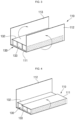
- FIG. 1 illustrates an insulating sheet used for a secondary battery according to an embodiment of the present disclosure.
- the insulating sheet 110 is made of an electrically insulating material and may be composed of a single or multiple (or a plurality of) layers.
- the insulating sheet 110 may cover side surfaces of the electrode assembly to prevent the electrode assembly from coming into contact with the case and causing an electrical short.
- the insulating sheet 110 may include, for example, polypropylene (PP).
- the insulating sheet 110 may have a first wing portion 112 and a second wing portion 113 positioned on (e.g., extending from) opposite edges of the seating portion 111.
- the seating portion 111 may have an area (e.g., a surface area) corresponding to a planar size of the electrode assembly.
- the seating portion 111 may be in contact with (e.g., may be attached to) the lower surface of the electrode assembly.
- the wing portions 112 and 113 may be folded upwardly to surround (or cover) the side surface of the electrode assembly while the electrode assembly is seated on the seating portion 111.
- the electrode uncoated region of each electrode plate e.g., of each polarity
- An adhesive component is applied to the inner surface of the seating portion 111 and the wing portions 112 and 113, and thus, the insulating sheet 110 may be adhered to an electrode assembly 130 and/or to a retainer 120, which is an internal component.
- the retainer 120 may be provided between the seating portion 111 of the insulating sheet 110 and the wing portions 112 and 113.
- the retainers 120 may be provided as a pair and may be respectively disposed on both sides (e.g., opposite sides) of the seating portion 111 of the insulating sheet 110.
- the wing portions 112 and 113 of the insulating sheet 110 may be folded upwardly together with the retainer 120 to be erect.
- the wing portions 112 and 113 may stand up the retainer 120 (e.g., the retainer 120 may be vertically arranged) through bending and, thus, may be respectively coupled to opposite sides of the electrode assembly.
- the retainer 120 may be coupled to two surfaces of the electrode assembly 130 facing each other having a relatively small area from among the four side surfaces of the electrode assembly 130. Therefore, the retainer 120 can cover the side surfaces of the electrode assembly 130 and protect the side surfaces from being scratched in the process of coupling a case to the outside of the electrode assembly 130, which will be described later, thereby preventing the electrode assembly 130 from being damaged.
- the retainer 120 may be a sheet member.
- the retainer 120 may be made of an electrically insulating material, similar to the insulating sheet 110.
- the retainer 120 may include polypropylene (PP) or high heat-resistant polyimide (PI). Accordingly, the retainer 120 may protect the side surfaces of the electrode assembly 130 while preventing the side surfaces of the electrode assembly 130 from contacting the case and being short-circuited.
- the retainer 120 may have a width smaller than the width of the short side portion of the electrode assembly 130.
- the retainer 120 may have a width that is not less than 1 mm, preferably not less than 1.5 mm or not less than 2 mm, smaller than the width of the short side portion (or short side surface) of the electrode assembly 130.
- the width of the retainer 120 may not exceed the width of (e.g., may be extend or protrude beyond) the electrode assembly 130, thereby preventing defects from occurring during the manufacture.
- a width difference may be illustrated in Fig. 1 and, after folding, in Figs. 4 and 5 where opposite end portions of the short side portions of the electrode assembly 130 are not covered by the retainer 120 due to the smaller width of the retainer 120 with respect to the width of the short side portion of the electrode assembly 130.
- the retainer 120 may not include a separate adhesive material on the inner surface thereof. Accordingly, physical or chemical damage that may occur to the electrode assembly due to an adhesive material on the retainer 120 may be avoided.
- FIG. 2 illustrates a process in which the electrode assembly is seated on the insulating sheet shown in FIG. 1 .
- the electrode assembly 130 may be positioned and attached to the seating portion 111 of the insulating sheet 110.
- the electrode assembly 130 is formed by stacking a plurality of layers including a first electrode plate, a separator, and a second electrode plate, each having a thin plate shape or a film shape.
- the first electrode plate may have a first polarity, for example, a positive electrode
- the second electrode plate may have a second polarity, for example, a negative electrode.
- the present disclosure is not limited thereto, and the first electrode plate and the second electrode plate may have any polarity as long as the first electrode plate and the second electrode plate have different polarities from each other.
- the first electrode plate is formed by coating a first electrode active material, such as a transition metal oxide, on a first electrode current collector formed of a metal foil, such as aluminum, and has a first electrode uncoated portion that is a region at where the first active material is not applied.
- the first electrode uncoated portion provides a passage for current flow between the first electrode plate and the outside.
- the first electrode uncoated portions of the first electrode plates may overlap each other at the same position (e.g., at a same end of the electrode assembly 130) when the first electrode plates are stacked.
- the first electrode uncoated portion protrudes toward one side of the electrode assembly 130, and the electrode plate to be coupled thereafter is combined with the first electrode uncoated portion to have the same polarity as the first electrode plate.
- the second electrode plate is formed by coating a second electrode active material, such as graphite or carbon, on a first electrode current collector formed of a metal foil, such as copper or nickel, and the second electrode uncoated portion is a region at where the second active material is not applied.
- a second electrode active material such as graphite or carbon
- the second electrode uncoated portions of the second electrode plates may overlap each other at the same position (e.g., at a same end of the electrode assembly 130) when the second electrode plates are stacked.
- the second electrode uncoated portion protrude toward the other side of the electrode assembly 130 to be coupled to the electrode plate.
- the separator is arranged between the first electrode plate and the second electrode plate to prevent short circuit and enable movement of lithium ions.
- the separator may be made of polyethylene, polypropylene, or a composite film of polyethylene and polypropylene. The present disclosure, however, is not limited by the material of the separator.
- the electrode assembly 130 is accommodated inside (e.g., substantially inside) the case together with the electrolyte.
- the electrolyte may be formed of a lithium salt, such as LiPF 6 or LiBF 4 , in an organic solvent, such as ethylene carbonate (EC), propylene carbonate (PC), diethyl carbonate (DEC), ethyl methyl carbonate (EMC), or dimethyl carbonate (DMC).
- EC ethylene carbonate
- PC propylene carbonate
- DEC diethyl carbonate
- EMC ethyl methyl carbonate
- DMC dimethyl carbonate
- the electrolyte may be in a liquid, solid or gel phase.
- the electrode assembly 130 may have a short side portion 131, a long side portion 132, and an electrode uncoated portion 133. From among these portions, the short side portion 131 and the long side portion 132 may form a side surface of the electrode assembly 130, and a region having a relatively small area may be referred as the short side portion 131, and a region having a relatively large area may be referred as the long side portion 132. In addition, electrode uncoated portions 133 may be formed at opposite ends of the electrode assembly 130 to be connected to the respective electrode plates.
- one surface of the long side portion 132 of the electrode assembly 130 may be positioned on the seating portion 111 of the insulating sheet 110 and adhered thereto.
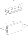
- FIGS. 3 to 5 illustrate a folding process of the insulating sheet around the electrode assembly shown in FIG. 2 .
- the wing portions 112 and 113 of the insulating sheet 110 may be bent along both edges of the side of the electrode assembly 130.
- the first wing portion 112 may be bent upwardly in a state in which the retainer 120 is provided therein and may be bent upwardly along one edge of the side portion from the lower surface corresponding to the long side portion 132 of the electrode assembly 130.
- the second wing portion 113 may be bent upwardly in a state in which the retainer 120 is provided therein and may be bent upwardly along the other edge from the side portion of the lower surface of the electrode assembly 130.
- the retainers 120 may be in contact with both sides of the electrode assembly 130, that is, the two short side portions 131, respectively.
- the first wing portion 112 may be bent once again and attached to surround (or cover) the upper surface of the electrode assembly 130.
- the end portion of the first wing portion 112 may extend over 1/2 or more of the width of the upper surface of the long side portion 132 of the electrode assembly 130.
- the retainer 120 located inside the first wing portion 112 is fixed to the side surface of the electrode assembly 130.
- the second wing portion 113 may be bent and attached to surround (or cover) the upper surface of the long side portion 132 of the electrode assembly 130.
- the second wing portion 113 may extend over 1/2 or more of the width of the upper surface of the electrode assembly 130.
- the end portion of the second wing portion 113 extends over the upper surface of the long side portion 132 to overlap the first wing portion 112 in some area.
- the overlapping area of the first wing portion 112 and the second wing portion 113 ensures that the upper surface of the electrode assembly 130 is completely covered. Because the second wing portion 113 is fixed to the upper surface of the electrode assembly 130 by being bent and attached thereto, the retainer 120 located inside the second wing portion 113 may be fixed to the side of the electrode assembly 130.
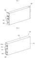
- FIG. 6 illustrates a process and a secondary battery 100 in which a current collector plate is coupled to the wrapped electrode assembly shown in FIG. 5 .
- current collector plates 140 and 150 may be coupled to the front and rear ends of the electrode assembly 130, which are exposed by the insulating sheet 110, respectively.
- the electrode assembly 130 includes a first electrode uncoated portion extending from the first electrode plate and a second electrode uncoated portion extending from the second electrode plate, and the first and second electrode uncoated portions may be respectively formed as front and rear ends of the electrode assembly 130.
- the first current collector plate 140 and the second current collector plate 150 may be coupled to the first electrode uncoated portion and the second electrode uncoated portion not covered by the insulating sheet 110, respectively.
- the first current collector plate 140 may include a current collecting portion 141 and a terminal portion 142.
- the current collecting portion 141 may be coupled by contacting the first electrode uncoated portions of the electrode assembly 130.
- the current collecting portion 141 may be arranged along the longitudinal direction of the first electrode uncoated portions of the electrode assembly 130 and may have a plurality of welding holes 141a formed in a direction perpendicular to the longitudinal direction of the current collecting portion 141. By irradiating a beam through the welding hole 141a to perform laser welding, the current collecting portion 141 and the first electrode uncoated portions of the electrode assembly may be electrically connected.
- the terminal portion 142 may protrude from an area of the current collecting portion 141.
- the terminal portion 142 may be (e.g., may extend) substantially perpendicular to the current collecting portion 141. Because the terminal portion 142 protrudes from the current collecting portion 141, the structure of the cap assembly can be easily welded thereafter. In addition, after welding, the terminal portion 142 may be bent about 90 degrees to be parallel to the current collecting portion 141, and through the bending operation of the terminal portion 142, the cap assembly may be closely coupled to the opening of the case.
- the second current collector plate 150 may similarly include a current collector 151 and a terminal 152.
- the second current collector plate 150 is coupled to the second current collector uncoated portions of the electrode assembly 130, and the configuration and operation thereof are the same or substantially the same as those of the first current collector plate 140, and thus, a detailed description thereof will be omitted.
- FIG. 7 illustrates a process and a secondary battery 100 in which an insulating member is coupled to the electrode assembly shown in FIG. 6 .
- the insulating member 160 may be coupled from the outside of each of the current collector plates 140 and 150.
- the insulating member 160 has a terminal hole (e.g., a terminal opening) 161 for exposing the terminal portions 142 and 152 while the current collecting portions 141 and 151 of the current collector plates 140 and 150 are covered from the outside so as not to be exposed. Accordingly, the current collector plates 140 and 150 are located inside the insulating member 160 and are not exposed to the outside, and only the terminal portions 142 and 152 are exposed to the outside through the terminal hole(s) 161.
- the insulating member 160 may be made of an electrically insulating material.
- the insulating member 160 may include polypropylene (PP).
- PP polypropylene
- the current collector plates 140 and 150 may be electrically independent (e.g., electrically isolated from each other) by the insulating member 160, except at the position where they are welded to the cap assembly, which will be described later. Accordingly, an electrical short circuit does not occur in the secondary battery according to embodiments of the present disclosure.
- the insulating member 160 may have an electrolyte injection hole (e.g., an electrolyte injection opening) 162 on one side to provide a path through which an electrolyte is injected into the inside of the case when the electrolyte is injected from the outside through the cap assembly after the coupling is completed.
- an electrolyte injection hole e.g., an electrolyte injection opening
- FIG. 8 illustrates a process and a secondary battery 100 in which a case is coupled to the insulating sheet used shown in FIG. 7 .
- the case 170 may be coupled to the coupling structure of the insulating sheet 110, the retainer 120, the electrode assembly 130, the current collector plates 140 and 150, and the insulating member 160.
- the case 170 may be configured as a tube having openings 170a at both ends, and a structure including the electrode assembly 130 may be inserted and coupled through the openings 170a.
- the retainer 120 is coupled to two surfaces of the electrode assembly 130 that face each other with a relatively small area from among the four side surfaces of the electrode assembly 130, and the outside thereof is covered by the insulating sheet 110.
- the side surface of the electrode assembly 130 has a relatively narrow area, the side surface of the electrode assembly are likely to be scratched when the electrode assembly 130 is inserted into the opening 170a of the case 170.
- the retainer 120 surrounds (or covers) the side surface, the side surface may not be scratched. Accordingly, when the case 170 is coupled to the electrode assembly 130, damage to the electrode assembly 130 can be prevented.
- FIG. 9 illustrates a process and a secondary battery 100 in which cap assemblies is coupled to the electrode assembly shown in FIG. 8 .
- the cap assemblies 180 and 190 may be coupled to the current collector plates 140 and 150, respectively, from the outside of the electrode assembly 130.
- the terminal portions 142 and 152 of the current collector plates 140 and 150 may be exposed to the outside through the terminal hole (e.g., terminal opening) 161 in the insulating member 160, respectively.
- the cap assemblies 180 and 190 may include a first cap assembly 180 coupled to the first current collector plate 140 and a second cap assembly 190 coupled to the second current collector plate 150.
- the first cap assembly 180 may include a flat cap plate 181, a terminal plate 182, and an insulating plate 183.
- the cap plate 181 has a flat plate shape and may have a shape matching the opening 170a in the case 170.
- the cap plate 181 may be formed of the same material as the case 170.
- the terminal plate 182 may be exposed to an upper portion of the cap plate 181 and may be electrically connected to the first current collector plate 140 therein through an electrode terminal penetrating the cap plate 181.
- the insulating plate 183 provided on the terminal plate 182 may insulate the terminal plate 182 and the cap plate 181 to be electrically independent from each other.
- the terminal plate 183 may have the same polarity as the first current collector plate 140 and the first electrode uncoated portion, regardless of the cap plate 181.
- an electrolyte injection hole e.g., an electrolyte injection opening
- 184 is formed in the cap plate 181 to provide a path through which an electrolyte is applied from the outside after the cap assembly 180 is assembled.
- the second cap assembly 190 may include a flat cap plate 191, a terminal plate 192, and an insulating plate 193 and may be electrically connected to the second current collector plate 150.
- the configuration and operation of the second cap assembly 190 are similar to those of the first cap assembly 180, and thus, a detailed description thereof will be omitted.
- FIG. 10 illustrates a process and a secondary battery 100 in which the case and the cap assembly shown in FIG. 9 are coupled together.
- the terminal portions 142 and 152 of the current collector plates 140 and 150 are bent by about 90 degrees so that the cap plates 181 and 191 can be coupled to the openings 170a in the case 170, respectively.
- the terminal plates 182 and 192 may protrude to the outside of the cap plates 181 and 191, respectively.
- welding may be performed along the boundaries of the cap plates 181 and 191 and the case 170, respectively.
- the welding may be laser welding, and accordingly, the inside of the cap plates 181 and 191 and the case 170 may be sealed.
- An electrolyte may be injected from the outside through the electrolyte injection hole 184 in the cap plate 181, and then, the electrolyte injection hole 184 may be closed and sealed by a separate injection plug.
- the terminal plates 182 and 192 may be respectively positioned through (or in) both ends of the case 170. Accordingly, lithium ions move through the entire area of the electrode assembly 130, thereby preventing partial (or uneven) deterioration of the electrode assembly 130 and, thus, lifespan and efficiency may be increased.
- the electrode assembly may not be damaged when the electrode assembly is inserted into a case.
Landscapes
- Chemical & Material Sciences (AREA)
- Chemical Kinetics & Catalysis (AREA)
- Electrochemistry (AREA)
- General Chemical & Material Sciences (AREA)
- Engineering & Computer Science (AREA)
- Manufacturing & Machinery (AREA)
- Materials Engineering (AREA)
- Secondary Cells (AREA)
- Connection Of Batteries Or Terminals (AREA)
- Cell Separators (AREA)
Applications Claiming Priority (1)
| Application Number | Priority Date | Filing Date | Title |
|---|---|---|---|
| KR1020220006822A KR20230111660A (ko) | 2022-01-17 | 2022-01-17 | 이차 전지 |
Publications (2)
| Publication Number | Publication Date |
|---|---|
| EP4213280A1 true EP4213280A1 (de) | 2023-07-19 |
| EP4213280B1 EP4213280B1 (de) | 2025-02-19 |
Family
ID=84981160
Family Applications (1)
| Application Number | Title | Priority Date | Filing Date |
|---|---|---|---|
| EP23151507.3A Active EP4213280B1 (de) | 2022-01-17 | 2023-01-13 | Sekundärbatterie |
Country Status (6)
| Country | Link |
|---|---|
| US (1) | US12586846B2 (de) |
| EP (1) | EP4213280B1 (de) |
| KR (1) | KR20230111660A (de) |
| CN (1) | CN116487674A (de) |
| HU (1) | HUE070817T2 (de) |
| PL (1) | PL4213280T3 (de) |
Families Citing this family (1)
| Publication number | Priority date | Publication date | Assignee | Title |
|---|---|---|---|---|
| EP4517943A3 (de) * | 2023-09-01 | 2025-04-23 | SK On Co., Ltd. | Batteriezelle und herstellungsverfahren dafür |
Citations (3)
| Publication number | Priority date | Publication date | Assignee | Title |
|---|---|---|---|---|
| EP3451416A1 (de) * | 2017-08-31 | 2019-03-06 | Samsung SDI Co., Ltd. | Sekundärbatterie und aufbauverfahren dafür |
| US10651499B2 (en) * | 2016-02-22 | 2020-05-12 | Samsung Sdi Co., Ltd. | Secondary battery |
| US20200295339A1 (en) * | 2019-03-11 | 2020-09-17 | Samsung Sdi Co., Ltd. | Secondary battery |
Family Cites Families (12)
| Publication number | Priority date | Publication date | Assignee | Title |
|---|---|---|---|---|
| US20120052341A1 (en) * | 2010-09-01 | 2012-03-01 | Duk-Jung Kim | Rechargeable battery |
| WO2013035668A1 (ja) * | 2011-09-09 | 2013-03-14 | 三洋電機株式会社 | 角形密閉二次電池及びその製造方法 |
| KR101684347B1 (ko) * | 2013-09-06 | 2016-12-08 | 주식회사 엘지화학 | 최외각면에 절연성 물질이 부가되어 있는 전극조립체 및 이를 포함하는 이차전지 |
| KR20160059748A (ko) * | 2014-11-19 | 2016-05-27 | 삼성에스디아이 주식회사 | 전극 조립체 및 이를 포함하는 배터리 팩 |
| JP6874525B2 (ja) * | 2017-05-25 | 2021-05-19 | 株式会社豊田自動織機 | 蓄電装置の製造方法 |
| JPWO2019131481A1 (ja) * | 2017-12-27 | 2021-01-21 | 株式会社Gsユアサ | 蓄電素子 |
| KR102475343B1 (ko) | 2018-03-02 | 2022-12-08 | 주식회사 엘지에너지솔루션 | 이차 전지 및 그의 제조 방법 |
| JP7246889B2 (ja) | 2018-10-19 | 2023-03-28 | 株式会社エンビジョンAescジャパン | 組電池およびその製造方法 |
| KR102455471B1 (ko) | 2019-02-18 | 2022-10-14 | 주식회사 엘지에너지솔루션 | 배터리 셀, 이를 포함하는 배터리 모듈, 배터리 랙 및 전력 저장 장치 |
| KR102757689B1 (ko) * | 2019-03-05 | 2025-01-21 | 삼성에스디아이 주식회사 | 이차전지 |
| KR102902223B1 (ko) * | 2020-05-29 | 2025-12-22 | 삼성에스디아이 주식회사 | 이차 전지 |
| US12431599B2 (en) * | 2021-03-18 | 2025-09-30 | Sk On Co., Ltd. | Electrode assembly preventing internal short, secondary battery comprising the same, battery module and battery pack |
-
2022
- 2022-01-17 KR KR1020220006822A patent/KR20230111660A/ko active Pending
-
2023
- 2023-01-12 US US18/153,953 patent/US12586846B2/en active Active
- 2023-01-13 EP EP23151507.3A patent/EP4213280B1/de active Active
- 2023-01-13 HU HUE23151507A patent/HUE070817T2/hu unknown
- 2023-01-13 PL PL23151507.3T patent/PL4213280T3/pl unknown
- 2023-01-16 CN CN202310059927.1A patent/CN116487674A/zh active Pending
Patent Citations (3)
| Publication number | Priority date | Publication date | Assignee | Title |
|---|---|---|---|---|
| US10651499B2 (en) * | 2016-02-22 | 2020-05-12 | Samsung Sdi Co., Ltd. | Secondary battery |
| EP3451416A1 (de) * | 2017-08-31 | 2019-03-06 | Samsung SDI Co., Ltd. | Sekundärbatterie und aufbauverfahren dafür |
| US20200295339A1 (en) * | 2019-03-11 | 2020-09-17 | Samsung Sdi Co., Ltd. | Secondary battery |
Also Published As
| Publication number | Publication date |
|---|---|
| US12586846B2 (en) | 2026-03-24 |
| US20230231237A1 (en) | 2023-07-20 |
| EP4213280B1 (de) | 2025-02-19 |
| CN116487674A (zh) | 2023-07-25 |
| HUE070817T2 (hu) | 2025-07-28 |
| PL4213280T3 (pl) | 2025-07-14 |
| KR20230111660A (ko) | 2023-07-26 |
Similar Documents
| Publication | Publication Date | Title |
|---|---|---|
| US11342636B2 (en) | Secondary battery | |
| EP3709392A1 (de) | Sekundärbatterie | |
| US20250046969A1 (en) | Secondary battery | |
| KR20160042243A (ko) | 이차 전지 및 그 제조 방법 | |
| EP3716386B1 (de) | Sekundärbatterie | |
| EP3799198B1 (de) | Sekundärbatterie | |
| EP4375004B1 (de) | Sekundärbatterie und herstellungsverfahren einer solchen sekundärbatterie | |
| US12087953B2 (en) | Secondary battery | |
| EP4366070A2 (de) | Sekundärbatterie mit geschweisster elektrodenanordnung | |
| KR20170109968A (ko) | 이차 전지 | |
| US8614015B2 (en) | Secondary battery and method of manufacturing secondary battery | |
| US20240356111A1 (en) | Secondary battery | |
| US10211446B2 (en) | Rechargeable battery | |
| US9153809B2 (en) | Secondary battery including retainer for electrode assembly | |
| US20230178861A1 (en) | Secondary battery | |
| US20240162524A1 (en) | Secondary battery | |
| EP4213280A1 (de) | Sekundärbatterie | |
| US20250192388A1 (en) | Secondary battery | |
| KR20180088202A (ko) | 이차 전지 | |
| US11664525B2 (en) | Method for manufacturing energy storage device and energy storage device | |
| US20250007122A1 (en) | Secondary battery and battery module including the same | |
| EP4462546A1 (de) | Elektrodenanordnung und verfahren zur herstellung davon sowie sekundärbatterie damit | |
| US20250105408A1 (en) | Secondary battery |
Legal Events
| Date | Code | Title | Description |
|---|---|---|---|
| PUAI | Public reference made under article 153(3) epc to a published international application that has entered the european phase |
Free format text: ORIGINAL CODE: 0009012 |
|
| STAA | Information on the status of an ep patent application or granted ep patent |
Free format text: STATUS: REQUEST FOR EXAMINATION WAS MADE |
|
| 17P | Request for examination filed |
Effective date: 20230113 |
|
| AK | Designated contracting states |
Kind code of ref document: A1 Designated state(s): AL AT BE BG CH CY CZ DE DK EE ES FI FR GB GR HR HU IE IS IT LI LT LU LV MC ME MK MT NL NO PL PT RO RS SE SI SK SM TR |
|
| GRAP | Despatch of communication of intention to grant a patent |
Free format text: ORIGINAL CODE: EPIDOSNIGR1 |
|
| STAA | Information on the status of an ep patent application or granted ep patent |
Free format text: STATUS: GRANT OF PATENT IS INTENDED |
|
| RIC1 | Information provided on ipc code assigned before grant |
Ipc: H01M 50/536 20210101ALN20240826BHEP Ipc: H01M 50/176 20210101ALN20240826BHEP Ipc: H01M 50/121 20210101ALI20240826BHEP Ipc: H01M 50/14 20210101AFI20240826BHEP |
|
| INTG | Intention to grant announced |
Effective date: 20240917 |
|
| GRAS | Grant fee paid |
Free format text: ORIGINAL CODE: EPIDOSNIGR3 |
|
| GRAA | (expected) grant |
Free format text: ORIGINAL CODE: 0009210 |
|
| STAA | Information on the status of an ep patent application or granted ep patent |
Free format text: STATUS: THE PATENT HAS BEEN GRANTED |
|
| AK | Designated contracting states |
Kind code of ref document: B1 Designated state(s): AL AT BE BG CH CY CZ DE DK EE ES FI FR GB GR HR HU IE IS IT LI LT LU LV MC ME MK MT NL NO PL PT RO RS SE SI SK SM TR |
|
| REG | Reference to a national code |
Ref country code: GB Ref legal event code: FG4D |
|
| REG | Reference to a national code |
Ref country code: CH Ref legal event code: EP |
|
| REG | Reference to a national code |
Ref country code: DE Ref legal event code: R096 Ref document number: 602023002043 Country of ref document: DE |
|
| REG | Reference to a national code |
Ref country code: IE Ref legal event code: FG4D |
|
| REG | Reference to a national code |
Ref country code: SE Ref legal event code: TRGR |
|
| REG | Reference to a national code |
Ref country code: NL Ref legal event code: MP Effective date: 20250219 |
|
| PG25 | Lapsed in a contracting state [announced via postgrant information from national office to epo] |
Ref country code: RS Free format text: LAPSE BECAUSE OF FAILURE TO SUBMIT A TRANSLATION OF THE DESCRIPTION OR TO PAY THE FEE WITHIN THE PRESCRIBED TIME-LIMIT Effective date: 20250519 |
|
| PG25 | Lapsed in a contracting state [announced via postgrant information from national office to epo] |
Ref country code: FI Free format text: LAPSE BECAUSE OF FAILURE TO SUBMIT A TRANSLATION OF THE DESCRIPTION OR TO PAY THE FEE WITHIN THE PRESCRIBED TIME-LIMIT Effective date: 20250219 |
|
| PG25 | Lapsed in a contracting state [announced via postgrant information from national office to epo] |
Ref country code: ES Free format text: LAPSE BECAUSE OF FAILURE TO SUBMIT A TRANSLATION OF THE DESCRIPTION OR TO PAY THE FEE WITHIN THE PRESCRIBED TIME-LIMIT Effective date: 20250219 |
|
| REG | Reference to a national code |
Ref country code: LT Ref legal event code: MG9D |
|
| PG25 | Lapsed in a contracting state [announced via postgrant information from national office to epo] |
Ref country code: IS Free format text: LAPSE BECAUSE OF FAILURE TO SUBMIT A TRANSLATION OF THE DESCRIPTION OR TO PAY THE FEE WITHIN THE PRESCRIBED TIME-LIMIT Effective date: 20250619 Ref country code: NO Free format text: LAPSE BECAUSE OF FAILURE TO SUBMIT A TRANSLATION OF THE DESCRIPTION OR TO PAY THE FEE WITHIN THE PRESCRIBED TIME-LIMIT Effective date: 20250519 |
|
| PG25 | Lapsed in a contracting state [announced via postgrant information from national office to epo] |
Ref country code: NL Free format text: LAPSE BECAUSE OF FAILURE TO SUBMIT A TRANSLATION OF THE DESCRIPTION OR TO PAY THE FEE WITHIN THE PRESCRIBED TIME-LIMIT Effective date: 20250219 |
|
| PG25 | Lapsed in a contracting state [announced via postgrant information from national office to epo] |
Ref country code: HR Free format text: LAPSE BECAUSE OF FAILURE TO SUBMIT A TRANSLATION OF THE DESCRIPTION OR TO PAY THE FEE WITHIN THE PRESCRIBED TIME-LIMIT Effective date: 20250219 |
|
| PG25 | Lapsed in a contracting state [announced via postgrant information from national office to epo] |
Ref country code: LV Free format text: LAPSE BECAUSE OF FAILURE TO SUBMIT A TRANSLATION OF THE DESCRIPTION OR TO PAY THE FEE WITHIN THE PRESCRIBED TIME-LIMIT Effective date: 20250219 Ref country code: PT Free format text: LAPSE BECAUSE OF FAILURE TO SUBMIT A TRANSLATION OF THE DESCRIPTION OR TO PAY THE FEE WITHIN THE PRESCRIBED TIME-LIMIT Effective date: 20250620 |
|
| PG25 | Lapsed in a contracting state [announced via postgrant information from national office to epo] |
Ref country code: BG Free format text: LAPSE BECAUSE OF FAILURE TO SUBMIT A TRANSLATION OF THE DESCRIPTION OR TO PAY THE FEE WITHIN THE PRESCRIBED TIME-LIMIT Effective date: 20250219 Ref country code: GR Free format text: LAPSE BECAUSE OF FAILURE TO SUBMIT A TRANSLATION OF THE DESCRIPTION OR TO PAY THE FEE WITHIN THE PRESCRIBED TIME-LIMIT Effective date: 20250520 |
|
| REG | Reference to a national code |
Ref country code: HU Ref legal event code: AG4A Ref document number: E070817 Country of ref document: HU |
|
| PG25 | Lapsed in a contracting state [announced via postgrant information from national office to epo] |
Ref country code: SM Free format text: LAPSE BECAUSE OF FAILURE TO SUBMIT A TRANSLATION OF THE DESCRIPTION OR TO PAY THE FEE WITHIN THE PRESCRIBED TIME-LIMIT Effective date: 20250219 |
|
| PG25 | Lapsed in a contracting state [announced via postgrant information from national office to epo] |
Ref country code: DK Free format text: LAPSE BECAUSE OF FAILURE TO SUBMIT A TRANSLATION OF THE DESCRIPTION OR TO PAY THE FEE WITHIN THE PRESCRIBED TIME-LIMIT Effective date: 20250219 |
|
| PG25 | Lapsed in a contracting state [announced via postgrant information from national office to epo] |
Ref country code: IT Free format text: LAPSE BECAUSE OF FAILURE TO SUBMIT A TRANSLATION OF THE DESCRIPTION OR TO PAY THE FEE WITHIN THE PRESCRIBED TIME-LIMIT Effective date: 20250219 |
|
| PG25 | Lapsed in a contracting state [announced via postgrant information from national office to epo] |
Ref country code: EE Free format text: LAPSE BECAUSE OF FAILURE TO SUBMIT A TRANSLATION OF THE DESCRIPTION OR TO PAY THE FEE WITHIN THE PRESCRIBED TIME-LIMIT Effective date: 20250219 Ref country code: CZ Free format text: LAPSE BECAUSE OF FAILURE TO SUBMIT A TRANSLATION OF THE DESCRIPTION OR TO PAY THE FEE WITHIN THE PRESCRIBED TIME-LIMIT Effective date: 20250219 |
|
| PG25 | Lapsed in a contracting state [announced via postgrant information from national office to epo] |
Ref country code: RO Free format text: LAPSE BECAUSE OF FAILURE TO SUBMIT A TRANSLATION OF THE DESCRIPTION OR TO PAY THE FEE WITHIN THE PRESCRIBED TIME-LIMIT Effective date: 20250219 |
|
| PG25 | Lapsed in a contracting state [announced via postgrant information from national office to epo] |
Ref country code: SK Free format text: LAPSE BECAUSE OF FAILURE TO SUBMIT A TRANSLATION OF THE DESCRIPTION OR TO PAY THE FEE WITHIN THE PRESCRIBED TIME-LIMIT Effective date: 20250219 |
|
| REG | Reference to a national code |
Ref country code: DE Ref legal event code: R097 Ref document number: 602023002043 Country of ref document: DE |
|
| PLBE | No opposition filed within time limit |
Free format text: ORIGINAL CODE: 0009261 |
|
| STAA | Information on the status of an ep patent application or granted ep patent |
Free format text: STATUS: NO OPPOSITION FILED WITHIN TIME LIMIT |
|
| PGFP | Annual fee paid to national office [announced via postgrant information from national office to epo] |
Ref country code: FR Payment date: 20251231 Year of fee payment: 4 |
|
| PGFP | Annual fee paid to national office [announced via postgrant information from national office to epo] |
Ref country code: PL Payment date: 20251230 Year of fee payment: 4 |
|
| 26N | No opposition filed |
Effective date: 20251120 |
|
| REG | Reference to a national code |
Ref country code: AT Ref legal event code: UEP Ref document number: 1769228 Country of ref document: AT Kind code of ref document: T Effective date: 20250219 |
|
| PGFP | Annual fee paid to national office [announced via postgrant information from national office to epo] |
Ref country code: HU Payment date: 20260130 Year of fee payment: 4 |
|
| PGFP | Annual fee paid to national office [announced via postgrant information from national office to epo] |
Ref country code: SE Payment date: 20251230 Year of fee payment: 4 |
|
| PGFP | Annual fee paid to national office [announced via postgrant information from national office to epo] |
Ref country code: DE Payment date: 20251230 Year of fee payment: 4 |
|
| PGFP | Annual fee paid to national office [announced via postgrant information from national office to epo] |
Ref country code: AT Payment date: 20260301 Year of fee payment: 4 |