EP4213558B1 - Datenübertragungsverfahren und zugehörige vorrichtung - Google Patents
Datenübertragungsverfahren und zugehörige vorrichtung Download PDFInfo
- Publication number
- EP4213558B1 EP4213558B1 EP20958354.1A EP20958354A EP4213558B1 EP 4213558 B1 EP4213558 B1 EP 4213558B1 EP 20958354 A EP20958354 A EP 20958354A EP 4213558 B1 EP4213558 B1 EP 4213558B1
- Authority
- EP
- European Patent Office
- Prior art keywords
- resource
- terminal device
- network device
- message
- resources
- Prior art date
- Legal status (The legal status is an assumption and is not a legal conclusion. Google has not performed a legal analysis and makes no representation as to the accuracy of the status listed.)
- Active
Links
Images



Classifications
-
- H—ELECTRICITY
- H04—ELECTRIC COMMUNICATION TECHNIQUE
- H04W—WIRELESS COMMUNICATION NETWORKS
- H04W72/00—Local resource management
- H04W72/20—Control channels or signalling for resource management
- H04W72/23—Control channels or signalling for resource management in the downlink direction of a wireless link, i.e. towards a terminal
-
- H—ELECTRICITY
- H04—ELECTRIC COMMUNICATION TECHNIQUE
- H04W—WIRELESS COMMUNICATION NETWORKS
- H04W76/00—Connection management
- H04W76/20—Manipulation of established connections
- H04W76/27—Transitions between radio resource control [RRC] states
-
- H—ELECTRICITY
- H04—ELECTRIC COMMUNICATION TECHNIQUE
- H04W—WIRELESS COMMUNICATION NETWORKS
- H04W72/00—Local resource management
- H04W72/04—Wireless resource allocation
- H04W72/044—Wireless resource allocation based on the type of the allocated resource
- H04W72/0453—Resources in frequency domain, e.g. a carrier in FDMA
-
- H—ELECTRICITY
- H04—ELECTRIC COMMUNICATION TECHNIQUE
- H04W—WIRELESS COMMUNICATION NETWORKS
- H04W72/00—Local resource management
- H04W72/04—Wireless resource allocation
- H04W72/11—Semi-persistent scheduling
-
- H—ELECTRICITY
- H04—ELECTRIC COMMUNICATION TECHNIQUE
- H04W—WIRELESS COMMUNICATION NETWORKS
- H04W76/00—Connection management
- H04W76/30—Connection release
Definitions
- This application relates to communication technologies, and in particular, to a data transmission method and a related apparatus.
- a terminal device in an idle state may implement data transmission with a network device by using an early data transmission (early data transmission, EDT) technology or a pre-configured uplink resource (pre-configured uplink resource, PUR) technology.
- EDT early data transmission
- PUR pre-configured uplink resource
- WO 2020/076032 A1 discloses a method for responding to a paging.
- the method includes receiving a configuration of a pre-allocated resource, receiving, in a paging occasion, information on type of resource for a response message, transmitting the response message on the pre-allocated resource, based on that the information informs the pre-allocated resource.
- EP 3 571 803 A2 discloses a wireless device that transmits one or more capability messages to a base station indicating that the wireless device supports a first number of channel state information processes per bandwidth part of a cell.
- One or more second messages are received that comprise: first configuration parameters of a first plurality of bandwidth parts of a first cell where the first plurality of bandwidth parts comprising a first bandwidth part; second configuration parameters indicating a plurality of channel state information reference signal resources; and third configuration parameters of a second number of channel state information processes for the first bandwidth part where the second number is smaller than or equal to the first number.
- First reference signals received via the plurality of channel state information reference signal resources are measured.
- Channel state information for the second number of channel state information processes are transmitted based on the measuring.
- This application provides two data transmission methods at interrelated entities/apparatuses (UE in idle/inactive state and network device) and the computer-readable medium storing computer program instructions to be run on both apparatuses/devices so that a terminal device in an idle state or an inactive state implements continuous and/or aperiodic data transmission.
- BWP configuration There are three types of BWP configuration: an initial BWP, an active (active) BWP, and a default (default) BWP.
- BWP switching includes the following four switching scenarios: fast switching indicated by downlink control information (downlink control information, DCI) for data scheduling; switching from the initial BWP to a first active BWP during RRC (re) configuration and activation of a secondary cell (secondary cell, SCell); switching based on timer (timer) when no service is scheduled for a long time; and automatically switching to the initial BWP if no physical random access channel (physical random access channel, PRACH) resource exists in the active BWP in the random access process.
- DCI downlink control information
- SCell secondary cell
- timer timer
- PRACH physical random access channel
- a first switching state is DCI_based switching.
- DCI switching is used to quickly implement BWP switching when there is data scheduling.
- a BWP indicator is used to indicate BWP switching.
- DCI format 0_1 and DCI format 1_1 may be used for DCI switching, but are not used only for DCI switching. If the active BWP indicated in the DCI received by the terminal device is different from a current active BWP, DCI switching is triggered. However, it should be noted that when the terminal device performs DCI BWP switching, data scheduled by the DCI needs to be transmitted on a new BWP.
- an information field size in the current DCI may not be the same as a size required for interpreting the information field by the new BWP. Therefore, 0 may need to be filled or several bits (bit) may need to be removed during interpretation.
- a second switching state is RRC_based switching.
- RRC BWP switching is used to enable the terminal device to enter a proper BWP to perform service receiving and sending after the terminal device completes initial access and enters a connected state, or after RRC reconfiguration or SCell activation, instead of always staying on the initial BWP.
- the terminal device In an initial access process, the terminal device always uses the initial BWP. In other words, some operations related to an SIB and random access (random access, RA) are usually completed in the initial BWP.
- a third switching state is timer_based switching.
- Timer_based switching is used when the terminal device does not perform service receiving or sending for a long time (which means that the terminal device may have no service requirement in this case), so that the terminal device switches to the default BWP with a relatively small bandwidth, to save energy.
- timer_based switching is required only for the downlink BWP, and is not required for the uplink BWP. This is because the downlink BWP has a large bandwidth and consumes more power.
- a specific duration is indicated by a bandwidth part inactivity timer (bwp inactivity timer) (the bwp inactivity timer indicates a duration in which there is no service), and a specific default BWP is indicated by a default downlink bandwidth part identifier (default downlink BWP ID).
- bwp inactivity timer bandwidth part inactivity timer
- default downlink BWP ID default downlink bandwidth part identifier
- the network device may activate a BWP other than the initial BWP by using the first active downlink bandwidth part identifier (first active downlink BWP ID) and the first active uplink bandwidth part identifier (first active uplink BWP ID).
- an active bandwidth is greater than that of the initial BWP.
- the terminal device automatically switches to an initial UL BWP, and a corresponding DL BWP also needs to be switched to a pair corresponding to the UL BWP. If the terminal device is switched to the initial UL BWP, an active DL BWP is also switched to an initial DL BWP. If the terminal device is not switched to the initial BWP, an ID of the active DL BWP needs to be the same as an ID of the active UL BWP. If they are different, the active DL BWP needs to be switched.
- the terminal device receives, in the random access process, BWP switching indicated by the DCI, whether the terminal device switches the BWP depends on behavior of the terminal device, or switches to a new BWP to start random access again, or ignores a switching indication.
- the terminal device receives, in the random access process, BWP switching indicated by an RRC configuration or reconfiguration indication, the terminal device needs to stop a current random access process, and perform BWP switching.
- SPS scheduling and release configuration can be viewed in the RRC reconfiguration message.
- Main configuration parameters are as follows: configured scheduling RNTI (configured scheduling-RNTI, CS-RNTI): used for activation, deactivation, and retransmission; periodicity (periodicity): SPS resource usage period; and quantity of HARQ processes (nrof HARQ-Processes): quantity of HARQ processes configured for SPS.
- a terminal device in an idle state may implement data transmission with a network device by using an early data transmission (early data transmission, EDT) technology or a pre-configured uplink resource (pre-configured uplink resource, PUR) technology.
- EDT early data transmission
- PUR pre-configured uplink resource
- Table 1 data transmission between a terminal device in an idle state and a network device EDT PUR Definition and description
- a terminal device in an idle state is allowed to perform uplink data transmission once in a random access process, and then perform corresponding downlink data transmission once (optional).
- a terminal device in an idle state is allowed to perform uplink transmission once by using a pre-configured uplink resource, and does not need to initiate a random access process.
- a data size is less than or equal to a transport block size (for example, 1 Kbits) indicated in system information.
- a data size is small, and a specific value is not defined in a protocol.
- One-shot transmission (one-shot transmission); One-shot transmission (one-shot transmission); one uplink data transmission + one downlink (optional) data transmission; one uplink data transmission + one downlink (optional) data transmission; a resource does not need to be pre-configured; and a resource needs to be pre-configured before an RRC connection is released; and a random access procedure needs to be initiated. a random access procedure does not need to be initiated.
- the technical solutions provided in embodiments of this application may be applicable to a plurality of system architectures.
- the network architecture and the service scenario described in embodiments of this application are intended to describe the technical solutions in embodiments of this application more clearly, and do not constitute a limitation on the technical solutions provided in embodiments of this application.
- a person of ordinary skill in the art may know that: With the evolution of the network architecture and the emergence of new service scenarios, the technical solutions provided in embodiments of this application are also applicable to similar technical problems.
- each device in FIG. 1 may be implemented by using a communication apparatus 200 in FIG. 2.
- FIG. 2 is a schematic diagram of a hardware structure applicable to a communication apparatus according to an embodiment of this application.
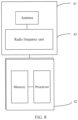
- the communication apparatus 200 includes at least one processor 201, a communication line 202, a memory 203, and at least one communication interface 204.
- the processor 201 may be a general-purpose central processing unit (central processing unit, CPU), a microprocessor, an application-specific integrated circuit (application-specific integrated circuit, ASIC), or one or more integrated circuits configured to control execution of programs in the solutions in this application.
- CPU central processing unit
- ASIC application-specific integrated circuit
- the communication interface 204 is any apparatus (such as an antenna) such as a transceiver, and is configured to communicate with another device or a communication network, such as Ethernet, a RAN, or a wireless local area network (wireless local area network, WLAN).
- a communication network such as Ethernet, a RAN, or a wireless local area network (wireless local area network, WLAN).
- the memory 203 may be a read-only memory (read-only memory, ROM) or another type of static storage device that can store static information and instructions, or a random access memory (random access memory, RAM) or another type of dynamic storage device that can store information and instructions.
- ROM read-only memory
- RAM random access memory
- the memory 203 may alternatively be an electrically erasable programmable read-only memory (electrically erasable programmable read-only memory, EEPROM), a compact disc read-only memory (compact disc read-only memory, CD-ROM) or another compact disc storage, optical disc storage (including a compact disc, a laser disc, an optical disc, a digital versatile disc, a Blu-ray disc, or the like), or magnetic disk storage medium or another magnetic storage device, or any other medium that can be used to carry or store expected program code in a form of instructions or a data structure and that is accessible to a computer, but is not limited thereto.
- the memory may exist independently, and is connected to the processor through the communication line 202.
- the memory may alternatively be integrated with the processor.
- the memory provided in embodiments of this application may be usually non-volatile.
- the memory 203 is configured to store computer-executable instructions for executing the solutions in this application, and the processor 201 controls the execution.
- the processor 201 is configured to execute the computer-executable instructions stored in the memory 203, to implement the method provided in the following embodiments of this application.
- the computer-executable instructions in this embodiment of this application may also be referred to as application program code. This is not specifically limited in this embodiment of this application.
- the processor 201 may include one or more CPUs, for example, a CPU 0 and a CPU 1 in FIG. 2 .
- the communication apparatus 200 may include a plurality of processors, for example, the processor 201 and a processor 207 in FIG. 2 .
- Each of the processors may be a single-core (single-CPU) processor, or may be a multi-core (multi-CPU) processor.
- the processor herein may be one or more devices, circuits, and/or processing cores configured to process data (for example, computer program instructions).
- the communication apparatus 200 may further include an output device 205 and an input device 206.
- the output device 205 communicates with the processor 201, and may display information in a plurality of manners.
- the output device 205 may be a liquid crystal display (liquid crystal display, LCD), a light emitting diode (light emitting diode, LED) display device, a cathode ray tube (cathode ray tube, CRT) display device, or a projector (projector).
- the input device 206 communicates with the processor 201, and may receive an input from a user in a plurality of manners.
- the input device 206 may be a mouse, a keyboard, a touchscreen device, or a sensor device.
- the foregoing communication apparatus 200 may be a general-purpose device or a special-purpose device.
- the communication apparatus 200 may be a desktop computer, a portable computer, a network server, a personal digital assistant (personal digital assistant, PDA), a mobile phone, a tablet computer, a wireless terminal device, an embedded device, or a device having a structure similar to that in FIG. 2 .
- PDA personal digital assistant
- a type of the communication apparatus 200 is not limited in this embodiment of this application.
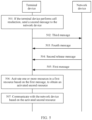
- FIG. 3 is a schematic flowchart of a data transmission method according to an embodiment of this application.
- a terminal device in FIG. 3 is the terminal device 20 in FIG. 1
- a network device in FIG. 3 is the network device 10 in FIG. 1 .
- the method includes but is not limited to the following steps.
- the network device sends a first message to the terminal device.
- the terminal device in an idle state or an inactive state receives the first message sent by the network device.
- the first indication information indicates to activate one or more of the BWP resources. If the first resource is the SPS resource, the first indication information indicates to activate one or more of the SPS resources. If the first resource is the BWP resource and the SPS resource, the first indication information indicates to activate the one or more of the BWP resources; the first indication information indicates to activate the one or more of the SPS resources; or the first indication information indicates to activate the one or more of the BWP resources and activate the one or more of the SPS resources.
- the BWP resource includes one or more uplink BWP resources and/or one or more downlink BWP resources.
- the first indication information includes a first field, or the first indication information includes a second field, or the first indication information includes a first field and a second field.
- the first field indicates that the one or more resources in the first resource are in an active state.
- the first field is a field negotiated by the terminal device and the network device in advance. To be specific, the terminal device may determine, based on the first field, which resource in the first resource is in the active state.
- the first indication information includes the second field, and the second field indicates that one or more resources that are in the first resource and that correspond to an identifier of the second resource are in the active state.
- the terminal device in the idle state or the inactive state sends uplink data to the network device based on the activated second resource, and the terminal device in the idle state or the inactive state receives downlink data sent by the network device based on the activated second resource.
- the uplink data includes assistance data involved in a positioning process, such as positioning assistance data, location information of the terminal device, or positioning measurement information or a sounding reference signal of the terminal device.
- assistance data involved in a positioning process, such as positioning assistance data, location information of the terminal device, or positioning measurement information or a sounding reference signal of the terminal device.
- steps 301 to 303 in FIG. 3 are applicable to a scenario in which a terminal device in an idle state or an inactive state sends a signal to a network device, or a scenario in which a terminal device in an idle state or an inactive state receives a signal sent by a network device, and are further applicable to a scenario in which a terminal device in an idle state or an inactive state needs to perform cell reselection.
- Steps 301 to 303 in FIG. 3 are not only applicable to a scenario in which a terminal device in an idle state or an inactive state does not perform cell reselection, but also applicable to a scenario in which a terminal device in an idle state or an inactive state needs to perform cell reselection.
- the terminal device When the terminal device needs to perform cell reselection, the terminal device is handed over from a network device being accessed before cell reselection to a network device being accessed after cell reselection.
- the network device accessed by the terminal device before cell reselection is referred to as a first network device or a source network device
- the network device accessed by the terminal device after cell reselection is referred to as a second network device.
- the network device in steps 301 to 303 in FIG. 3 may be the first network device (source network device) or the second network device (target network device). This is not limited in this application.
- the following embodiments respectively describe the scenario in which the terminal device in the idle state or the inactive state sends the signal to the network device, or the scenario in which the terminal device in the idle state or the inactive state receives the signal sent by the network device, and the scenario in which the terminal device in the idle state or the inactive state needs to perform cell reselection.
- the method further includes: The first message further includes second indication information, and the second indication information is used to deactivate the one or more resources in the first resource; and deactivating the one or more resources in the first resource based on the second indication information, to obtain a deactivated third resource.
- the second indication information indicates to deactivate one or more of the BWP resources. If the first resource is the SPS resource, the second indication information indicates to deactivate the one or more of the SPS resources. If the first resource is the BWP resource and the SPS resource, the second indication information indicates to deactivate the one or more of the BWP resources; the second indication information indicates to deactivate the one or more of the SPS resources; or the second indication information indicates to deactivate the one or more of the BWP resources and deactivate the one or more of the SPS resources.
- the second indication information includes a third field
- the third field indicates that the one or more resources in the first resource are in the inactive state.
- the third field is a field negotiated by the terminal device and the network device in advance.
- the terminal device may determine, based on the third field, which resource in the first resource is in the inactive state.
- the third field may be the same as or different from the first field. This is not limited herein.
- the second indication information includes a fourth field, and the fourth field indicates that one or more resources corresponding to an identifier of the third resource in the first resource are in the inactive state.
- the second indication information includes the fourth field, and the fourth field is a resource identifier.
- the resource identifier is the identifier of the third resource, and the resource identifier indicates that the one or more resources that are in the first resource and that correspond to the identifier of the third resource are in the inactive state.
- the terminal device can deactivate the resource based on the indication information.
- the network device may separately deliver first messages that indicate that different resources are in the active state and/or the inactive state, so that the terminal device in the idle state or the inactive state includes the first messages that indicate that the different resources are in the active state and/or the inactive state, to activate and/or deactivate a resource.
- the first resource includes the first uplink BWP resource and the second uplink BWP resource.
- the first uplink BWP resource is in the active state
- the second uplink BWP resource is in the inactive state.
- the first uplink BWP resource is in the inactive state
- the second uplink BWP resource is in the active state.
- a state of the resource may be switched at different moments.
- FIG. 4 is a schematic flowchart of another data transmission method according to an embodiment of this application.
- a terminal device in FIG. 4 is the terminal device 20 in FIG. 1
- a network device in FIG. 4 is the network device 10 in FIG. 1 .
- the method is applicable to a scenario in which a terminal device in an idle state or an inactive state sends a signal to a network device, or a terminal device in an idle state or an inactive state receives a signal sent by a network device.
- the method includes but is not limited to the following steps.
- the terminal device receives a first release message sent by the network device, and correspondingly, the network device sends the first release message to the terminal device.
- the first release message indicates the terminal device to reserve a first resource after entering the idle state or the inactive state, or the first release message includes configuration information of the first resource.
- the first release message includes third indication information, and the third indication information indicates the terminal device to reserve the first resource after entering the idle state or the inactive state.
- the third indication information includes an identifier of the first resource, and the third indication information indicates the terminal device to reserve, after entering the idle state or the inactive state, the first resource corresponding to the identifier of the first resource.
- the first release message includes fourth indication information, and the fourth indication information includes the configuration information of the first resource.
- the first release message is sent by a network device in a cell existing before the terminal device performs cell reselection or a network device in a cell in which the terminal device is currently located.
- the first release message further indicates the terminal device to release a connection between the terminal device and a network device in a cell existing before the terminal device performs cell reselection or a network device in a cell in which the terminal device is currently located.
- the first release message is a first RRC release message.
- the third indication information may be, for example, a SuspendConfig field.
- the SuspendConfig field includes the identifier of the first resource.
- the SuspendConfig field indicates the terminal device to reserve, after entering the idle state or the inactive state, the first resource corresponding to the identifier of the first resource.
- the fourth indication information may be, for example, a SuspendConfig field, and the SuspendConfig field includes the configuration information of the first resource.
- the configuration information of the first resource includes an SCS, a cyclic prefix (cyclic prefix, CP), a frequency domain location, a size (an indication manner is an RIV), an ID, a PDCCH in the BWP, and a common parameter and a dedicated parameter (generic parameters and dedicate parameters) of a PDSCH in the BWP.
- the configuration information of the first resource includes a CS-RNTI and periodicity.
- the configuration information of the first resource includes: an SCS, a cyclic prefix (cyclic prefix, CP), a frequency domain location, a size (an indication manner is an RIV), an ID, a PDCCH in the BWP, a common parameter and a dedicated parameter (generic parameters and dedicate parameters) of a PDSCH in the BWP, a CS-RNTI, and periodicity.
- Steps 402 to 404 are the same as steps 301 to 303 in FIG. 3 , and details are not described herein again.
- the network device in the cell in which the terminal device is located before the terminal device performs cell reselection or the network device in the cell in which the terminal device is currently located configures the first resource for the terminal device, and sends the first message to the terminal device in the idle state or the inactive state, so that the terminal device in the idle state or the inactive state activates the one or more resources in the first resource based on the first message. Therefore, the terminal device in the idle state or the inactive state can communicate with the network device based on an activated BWP resource and/or an activated SPS resource. This implements continuous or periodic data transmission. In addition, because the terminal device implements continuous or periodic data transmission when the terminal device does not establish a connection to the network device, energy consumption of the terminal device is reduced.
- FIG. 5 is a schematic flowchart of still another data transmission method according to an embodiment of this application.
- a terminal device in FIG. 5 is the terminal device 20 in FIG. 1
- a network device in FIG. 5 is the network device 10 in FIG. 1 .
- the method in a scenario in which the terminal device in an idle state or an inactive state needs to perform cell reselection, the method includes but is not limited to the following steps.
- the terminal device in the idle state or the inactive state sends a second message to the network device.
- the network device receives the second message sent by the terminal device.
- the second message is used to initiate random access to the network device, and the network device is a network device in a cell obtained after the terminal device performs cell reselection.
- step 502 may be performed or not performed. This is not limited in this application.
- the communication apparatus 600 when the communication apparatus is used as the network device or is a chip applied to a network device, the communication apparatus 600 includes the transceiver module 602, and performs the steps performed by the network device in the foregoing method embodiments.
- the transceiver module 602 is configured to support communication with a terminal device and the like, and specifically perform the sending and/or receiving action performed by the network device in FIG. 6 . Details are not described herein again.
- the network device is supported in performing one or more of step 301 and step 502, and/or another process of the technology described in this specification.
- the transceiver module 602 may be an interface, a pin, a circuit, or the like.
- the interface may be configured to input to-be-processed data to a processor, and may output a processing result of the processor to the outside.
- the interface may be a general-purpose input/output (general-purpose input/output, GPIO) interface, and may be connected to a plurality of peripheral devices (for example, a display (LCD), a camera (camera), a radio frequency (radio frequency, RF) module, and an antenna).
- the interface is connected to the processor through a bus.
- the processing module 601 may be a processor.
- the processor may execute computer-executable instructions stored in a storage module, so that the chip performs the methods according to the embodiments in FIG. 3, FIG. 4 , or FIG. 5 .
- the processor may include a controller, an arithmetic unit, and a register.
- the controller is mainly responsible for decoding instructions and sending a control signal for an operation corresponding to the instructions.
- the arithmetic unit is mainly responsible for performing a fixed-point or floating-point arithmetic operation, a shift operation, a logic operation, and the like, and may also perform an address operation and address translation.
- the register is mainly responsible for saving a quantity of register operations, intermediate operation results, and the like that are temporarily stored during instruction execution.
- the storage module 603 may be a storage module inside the chip, for example, a register or a cache.
- the storage module may be a storage module located outside the chip, for example, a read-only memory (read-only memory, ROM), another type of static storage device that can store static information and instructions, or a random access memory (random access memory, RAM).
- ROM read-only memory
- RAM random access memory
- an antenna having sending and receiving functions and the radio frequency circuit may be considered as a receiving unit and a sending unit (which may also be collectively referred to as a transceiver unit) of the terminal device, and a processor having a processing function may be considered as a processing unit of the terminal device.
- the terminal device includes a receiving module 31, a processing module 32, and a sending module 33.
- the receiving module 31 may also be referred to as a receiver, a receiver circuit, or the like.
- the sending module 33 may also be referred to as a transmitter, a transmitter circuit, or the like.
- the processing module 32 may also be referred to as a processor, a processing board, a processing apparatus, or the like.
Landscapes
- Engineering & Computer Science (AREA)
- Computer Networks & Wireless Communication (AREA)
- Signal Processing (AREA)
- Mobile Radio Communication Systems (AREA)
Claims (15)
- Datenübertragungsverfahren, umfassend:Empfangen (301, 402, 505) einer ersten durch eine Netzwerkvorrichtung (10) gesendeten Nachricht durch eine Endgerätevorrichtung (20) in einem Leerlaufzustand oder einem inaktiven Zustand;Aktivieren (302, 403, 506) einer oder mehrerer Ressourcen in einer ersten Ressource durch die Endgerätevorrichtung (20) in dem Leerlaufzustand oder in dem inaktiven Zustand basierend auf der ersten Nachricht, um eine aktivierte zweite Ressource zu erlangen, wobei die erste Ressource eine Bandbreitenteilressource, BWP-Ressource, und/oder eine semipersistente Planungsressource, SPS-Ressource, umfasst; undKommunizieren (303, 404, 507), durch die Endgerätevorrichtung (20) in dem Leerlaufzustand oder in dem inaktiven Zustand, mit der Netzwerkvorrichtung (10) basierend auf der aktivierten zweiten Ressource;wobei das Verfahren dadurch gekennzeichnet ist, dass das Aktivieren einer oder mehrerer Ressourcen in einer ersten Ressource basierend auf der ersten Nachricht, um eine aktivierte zweite Ressource zu erlangen, ferner Folgendes umfasst:die erste Nachricht umfasst erste Anzeigeinformationen, die ein Feld beinhalten, und die ersten Anzeigeinformationen werden verwendet, um die eine oder die mehreren Ressourcen in der ersten Ressource zu aktivieren, wobei das Feld anzeigt, dass sich eine oder mehrere Ressourcen, die sich in der ersten Ressource befinden und einer Kennung der aktivierten zweiten Ressource entsprechen, in dem aktiven Zustand befinden; undAktivieren der einen oder der mehreren Ressourcen in der ersten Ressource basierend auf den ersten Anzeigeinformationen, um die aktivierte zweite Ressource zu erlangen.
- Verfahren nach Anspruch 1, wobei das Verfahren vor dem Empfangen (301, 402, 505) einer ersten Nachricht, die durch eine Netzwerkvorrichtung (10) gesendet wird, ferner Folgendes umfasst:
Empfangen (401) einer ersten Freigabenachricht, die durch die Netzwerkvorrichtung (10) gesendet wird, wobei die erste Freigabenachricht der Endgerätevorrichtung (20) anzeigt, die erste Ressource nach dem Wechseln in den Leerlaufzustand oder den inaktiven Zustand zu reservieren, oder wobei die erste Freigabenachricht Konfigurationsinformationen der ersten Ressource umfasst. - Verfahren nach Anspruch 1, wobei, wenn die Endgerätevorrichtung (20) eine Zellneuauswahl durchführt, das Verfahren vor dem Empfangen (301, 402, 505) einer ersten Nachricht, die durch eine Netzwerkvorrichtung (10) gesendet wird, ferner Folgendes umfasst:Senden einer zweiten Nachricht an die Netzwerkvorrichtung (10), wobei die zweite Nachricht zum Initiieren eines wahlfreien Zugriffs auf die Netzwerkvorrichtung (10) verwendet wird und die Netzwerkvorrichtung (10) eine Netzwerkvorrichtung (10) in einer durch die Endgerätevorrichtung (20) neu ausgewählten Zelle ist;wobei das Verfahren optional ferner Folgendes umfasst:Senden (502) einer dritten Nachricht an die Netzwerkvorrichtung (10), wobei die dritte Nachricht zum Anfordern der ersten Ressource verwendet wird; undEmpfangen (503) einer durch die Netzwerkvorrichtung (10) gesendeten vierten Nachricht, wobei die vierte Nachricht Konfigurationsinformationen der ersten Ressource umfasst.
- Verfahren nach Anspruch 3, wobei das Verfahren, nachdem die Netzwerkvorrichtung (10) eine Verbindung der Funkressourcensteuerung, RRC-Verbindung, mit der Endgerätevorrichtung (20) hergestellt hat, ferner Folgendes umfasst:
Empfangen (504) einer zweiten Freigabenachricht, die durch die Netzwerkvorrichtung gesendet wird, wobei die zweite Freigabenachricht der Endgerätevorrichtung anzeigt, dass die RRC-Verbindung freizugeben ist. - Verfahren nach einem der Ansprüche 1 bis 4, wobei das Verfahren ferner Folgendes umfasst:die erste Nachricht umfasst ferner zweite Anzeigeinformationen, und die zweiten Anzeigeinformationen werden verwendet, um die eine oder die mehreren Ressourcen in der ersten Ressource zu deaktivieren; undDeaktivieren der einen oder der mehreren Ressourcen in der ersten Ressource basierend auf den zweiten Anzeigeinformationen, um die deaktivierte dritte Ressource zu erlangen.
- Datenübertragungsverfahren, umfassend:Senden (301, 402, 505) einer ersten Nachricht durch eine Netzwerkvorrichtung (10) an eine Endgerätevorrichtung (20); undKommunizieren (303, 404, 507), durch die Netzwerkvorrichtung (10), mit der Endgerätevorrichtung (20) basierend auf einer aktivierten zweiten Ressource, wobei die aktivierte zweite Ressource durch die Endgerätevorrichtung (20) in einem Leerlaufzustand oder einem inaktiven Zustand durch Aktivieren einer oder mehrerer Ressourcen in einer ersten Ressource basierend auf der ersten Nachricht erlangt wird, und die erste Ressource eine Bandbreitenteilressource, BWP-Ressource, und/oder eine semipersistente Planungsressource, SPS-Ressource, umfasst;das Verfahren dadurch gekennzeichnet ist, dass die erste Nachricht erste Anzeigeinformationen umfasst, die ein Feld beinhalten, und die ersten Anzeigeinformationen verwendet werden, um die eine oder die mehreren Ressourcen in der ersten Ressource zu aktivieren, wobei das Feld anzeigt, dass sich eine oder mehrere Ressourcen, die sich in der ersten Ressource befinden und einer Kennung der aktivierten zweiten Ressource entsprechen, in dem aktiven Zustand befinden.
- Verfahren nach Anspruch 6, wobei das Verfahren vor dem Senden (301, 402, 505) einer ersten Nachricht an eine Endgerätevorrichtung (20) ferner Folgendes umfasst:
Senden (401) einer ersten Freigabenachricht an die Endgerätevorrichtung (20) gesendet wird, wobei die erste Freigabenachricht der Endgerätevorrichtung (20) anzeigt, die erste Ressource nach dem Wechseln in den Leerlaufzustand oder den inaktiven Zustand zu reservieren, oder wobei die erste Freigabenachricht Konfigurationsinformationen der ersten Ressource umfasst. - Verfahren nach Anspruch 6, wobei das Verfahren vor dem Senden (301, 402, 505) einer ersten Nachricht an eine Endgerätevorrichtung (20) ferner Folgendes umfasst:Empfangen einer zweiten Nachricht, die durch die Endgerätevorrichtung (20) gesendet wird, wobei die zweite Nachricht zum Initiieren eines wahlfreien Zugriffs auf eine Netzwerkvorrichtung (10) verwendet wird und die Netzwerkvorrichtung (10) eine Netzwerkvorrichtung (10) in einer durch die Endgerätevorrichtung neu ausgewählten Zelle ist;wobei das Verfahren optional ferner Folgendes umfasst:Empfangen (502) einer dritten Nachricht, die durch die Endgerätevorrichtung (20) gesendet wird, wobei die dritte Nachricht zum Anfordern der ersten Ressource verwendet wird; undSenden (503) einer vierten Nachricht an die Endgerätevorrichtung (20), wobei die vierte Nachricht die Konfigurationsinformationen der ersten Ressource umfasst.
- Verfahren nach Anspruch 8, wobei das Verfahren, nachdem die Netzwerkvorrichtung eine Verbindung der Funkressourcensteuerung, RRC-Verbindung, mit der Endgerätevorrichtung hergestellt hat, ferner Folgendes umfasst:
Senden (504) einer zweiten Freigabenachricht an die Endgerätevorrichtung (20), wobei die zweite Freigabenachricht der Endgerätevorrichtung (20) anzeigt, dass die RRC-Verbindung freizugeben ist. - Verfahren nach einem der Ansprüche 6 bis 9, wobei die erste Nachricht ferner zweite Anzeigeinformationen umfasst, und die zweiten Anzeigeinformationen verwendet werden, um die eine oder die mehreren Ressourcen in der ersten Ressource zu deaktivieren.
- Endgerätevorrichtung (20), wobei sich die Endgerätevorrichtung (20) in einem Leerlaufzustand oder einem inaktiven Zustand befindet und die Endgerätevorrichtung (20) ein Sende-Empfangsmodul (602) und ein Verarbeitungsmodul (601) umfasst;das Sende-Empfangsmodul (602) dazu konfiguriert ist, eine durch eine Netzwerkvorrichtung (10) gesendete erste Nachricht zu empfangen;das Verarbeitungsmodul (601) dazu konfiguriert ist, eine oder mehrere Ressourcen in einer ersten Ressource basierend auf der ersten Nachricht zu aktivieren, um eine aktivierte zweite Ressource zu erlangen, wobei die erste Ressource eine Bandbreitenteilressource, BWP-Ressource, und/oder eine semipersistente Planungsressource, SPS-Ressource, umfasst; und das Sende-Empfangsmodul (602) dazu konfiguriert ist, basierend auf der aktivierten zweiten Ressource mit der Netzwerkvorrichtung (10) zu kommunizieren;wobei die Endgerätevorrichtung (20) dadurch gekennzeichnet ist, dass:die erste Nachricht erste Anzeigeinformationen umfasst, die ein Feld beinhalten, und die ersten Anzeigeinformationen verwendet werden, um die eine oder die mehreren Ressourcen in der ersten Ressource zu aktivieren, wobei das Feld anzeigt, dass sich eine oder mehrere Ressourcen, die sich in der ersten Ressource befinden und einer Kennung der aktivierten zweiten Ressource entsprechen, in dem aktiven Zustand befinden; unddas Verarbeitungsmodul ferner dazu konfiguriert ist, die eine oder die mehreren Ressourcen in der ersten Ressource basierend auf den ersten Anzeigeinformationen zu aktivieren, um die aktivierte zweite Ressource zu erlangen.
- Endgerätevorrichtung (20) nach Anspruch 11, wobei die Endgerätevorrichtung (20) ferner dazu konfiguriert ist, das Verfahren nach einem der Ansprüche 2 bis 5 durchzuführen.
- Netzwerkvorrichtung (10), wobei die Netzwerkvorrichtung (10) ein Sende-Empfangsmodul (602) und ein Verarbeitungsmodul (601) umfasst;das Sende-Empfangsmodul (602) dazu konfiguriert ist, eine erste Nachricht an eine Endgerätevorrichtung (20) zu senden; unddas Verarbeitungsmodul (601) dazu konfiguriert ist, basierend auf einer aktivierten zweiten Ressource mit der Endgerätevorrichtung (20) zu kommunizieren, wobei die aktivierte zweite Ressource durch die Endgerätevorrichtung (20) in einem Leerlaufzustand oder einem inaktiven Zustand durch Aktivieren einer oder mehrerer Ressourcen in einer ersten Ressource basierend auf der ersten Nachricht erlangt wird, und die erste Ressource eine Bandbreitenteilressource, BWP-Ressource, und/oder eine semipersistente Planungsressource, SPS-Ressource, umfasst;die Netzwerkvorrichtung (10) dadurch gekennzeichnet ist, dass die erste Nachricht erste Anzeigeinformationen umfasst, die ein Feld beinhalten, und die ersten Anzeigeinformationen verwendet werden, um die eine oder die mehreren Ressourcen in der ersten Ressource zu aktivieren, wobei das Feld anzeigt, dass sich eine oder mehrere Ressourcen, die sich in der ersten Ressource befinden und einer Kennung der aktivierten zweiten Ressource entsprechen, in dem aktiven Zustand befinden.
- Netzwerkvorrichtung (10) nach Anspruch 13, wobei die Netzwerkvorrichtung (10) ferner dazu konfiguriert ist, das Verfahren nach einem der Ansprüche 7 bis 10 durchzuführen.
- Computerlesbares Speichermedium, wobei das computerlesbare Speichermedium ein Computerprogramm speichert und bei Ausführung des Computerprogramms durch Verarbeitungsmodule einer Endgerätevorrichtung (20) die Endgerätevorrichtung (20) dazu befähigt ist, das Verfahren nach einem der Ansprüche 1 bis 5 zu implementieren, und bei Ausführung des Computerprogramms durch ein Verarbeitungsmodul einer Netzwerkvorrichtung (10) die Netzwerkvorrichtung (10) dazu befähigt ist, das Verfahren nach einem der Ansprüche 6 bis 10 zu implementieren.
Applications Claiming Priority (1)
| Application Number | Priority Date | Filing Date | Title |
|---|---|---|---|
| PCT/CN2020/123407 WO2022082772A1 (zh) | 2020-10-23 | 2020-10-23 | 一种数据传输方法和相关装置 |
Publications (3)
| Publication Number | Publication Date |
|---|---|
| EP4213558A1 EP4213558A1 (de) | 2023-07-19 |
| EP4213558A4 EP4213558A4 (de) | 2023-11-22 |
| EP4213558B1 true EP4213558B1 (de) | 2025-06-25 |
Family
ID=81291144
Family Applications (1)
| Application Number | Title | Priority Date | Filing Date |
|---|---|---|---|
| EP20958354.1A Active EP4213558B1 (de) | 2020-10-23 | 2020-10-23 | Datenübertragungsverfahren und zugehörige vorrichtung |
Country Status (3)
| Country | Link |
|---|---|
| EP (1) | EP4213558B1 (de) |
| CN (1) | CN116134923B (de) |
| WO (1) | WO2022082772A1 (de) |
Families Citing this family (3)
| Publication number | Priority date | Publication date | Assignee | Title |
|---|---|---|---|---|
| CN120303986A (zh) * | 2022-12-09 | 2025-07-11 | Oppo广东移动通信有限公司 | 通信方法及通信装置 |
| WO2025020134A1 (zh) * | 2023-07-26 | 2025-01-30 | 北京小米移动软件有限公司 | 控制物联网设备的方法、设备和存储介质 |
| CN121547871A (zh) * | 2024-08-09 | 2026-02-17 | 荣耀终端股份有限公司 | 一种数据传输方法及系统 |
Citations (1)
| Publication number | Priority date | Publication date | Assignee | Title |
|---|---|---|---|---|
| WO2020032659A1 (en) * | 2018-08-09 | 2020-02-13 | Samsung Electronics Co., Ltd. | Apparatus and method for idle mode uplink transmission in wireless communication system |
Family Cites Families (7)
| Publication number | Priority date | Publication date | Assignee | Title |
|---|---|---|---|---|
| CN108738139B (zh) * | 2017-04-18 | 2022-01-11 | 华为技术有限公司 | 下行数据传输方法及装置 |
| US11025372B2 (en) * | 2017-10-26 | 2021-06-01 | Qualcomm Incorporated | Semi-persistent scheduling management in new radio |
| WO2019084570A1 (en) * | 2017-10-26 | 2019-05-02 | Hyoungsuk Jeon | BANDWIDTH PART INACTIVITY TIMER |
| PL3591887T3 (pl) * | 2017-11-09 | 2022-04-25 | Beijing Xiaomi Mobile Software Co., Ltd. | Sposoby i urządzenia do prowadzenia łączności na podstawie możliwości urządzenia bezprzewodowego |
| US10855396B2 (en) * | 2018-01-04 | 2020-12-01 | Ofinno, Llc | Semi-persistent channel state information report |
| EP3512265B1 (de) * | 2018-01-10 | 2022-05-11 | Comcast Cable Communications LLC | Leistungsregelung für kanalzustandsinformationen |
| WO2020076032A1 (en) * | 2018-10-07 | 2020-04-16 | Lg Electronics Inc. | Response to paging for data reception |
-
2020
- 2020-10-23 WO PCT/CN2020/123407 patent/WO2022082772A1/zh not_active Ceased
- 2020-10-23 EP EP20958354.1A patent/EP4213558B1/de active Active
- 2020-10-23 CN CN202080105192.6A patent/CN116134923B/zh active Active
Patent Citations (1)
| Publication number | Priority date | Publication date | Assignee | Title |
|---|---|---|---|---|
| WO2020032659A1 (en) * | 2018-08-09 | 2020-02-13 | Samsung Electronics Co., Ltd. | Apparatus and method for idle mode uplink transmission in wireless communication system |
Also Published As
| Publication number | Publication date |
|---|---|
| EP4213558A4 (de) | 2023-11-22 |
| WO2022082772A1 (zh) | 2022-04-28 |
| CN116134923A8 (zh) | 2024-05-24 |
| CN116134923A (zh) | 2023-05-16 |
| CN116134923B (zh) | 2025-12-12 |
| EP4213558A1 (de) | 2023-07-19 |
Similar Documents
| Publication | Publication Date | Title |
|---|---|---|
| EP3809761B1 (de) | Überwachungsverfahren und -vorrichtung | |
| CN115023981B (zh) | 用于rrc非活动状态的寻呼的wus | |
| US20220417985A1 (en) | Communication method and apparatus | |
| CN110933748B (zh) | 一种无线通信方法和装置 | |
| US20220286960A1 (en) | Multi-RAT Wireless Communication | |
| US20240373265A1 (en) | Ue based pdcch monitoring adaptation during sdt | |
| WO2023138510A1 (zh) | 配置确定方法、装置、终端及网络侧设备 | |
| EP4213558A1 (de) | Datenübertragungsverfahren und zugehörige vorrichtung | |
| WO2021158154A1 (en) | Method and user equipment for communication with a wireless network for handling multiple bandwidth parts, bwp | |
| US20260020030A1 (en) | Resource configuration method and apparatus, terminal, device, and storage medium | |
| EP4307750A1 (de) | Kommunikationsverfahren und -vorrichtung | |
| EP4460106A1 (de) | Drahtloskommunikationsverfahren, endgerätevorrichtung und netzwerkvorrichtung | |
| CN117957881A (zh) | 无线设备的超精简随机接入 | |
| US20240064861A1 (en) | Communication method and related apparatus | |
| US11871475B2 (en) | Wireless communication system, base station, mobile station, and method of wireless communication | |
| CN113826421B (zh) | 激活终端的方法及装置 | |
| EP4561207A1 (de) | Funkrufantwortverfahren und -vorrichtung | |
| CN113950132A (zh) | 一种无线通信方法和装置 | |
| WO2026086890A1 (zh) | 通信方法及装置、存储介质、计算机程序产品 | |
| WO2025055861A1 (zh) | 连接态非连续接收的配置方法、终端及网络侧设备 | |
| CN119450807A (zh) | 用于双连接中的双多网络操作的机制 | |
| WO2021026835A1 (zh) | 一种系统信息的获取方法、发送方法及装置 |
Legal Events
| Date | Code | Title | Description |
|---|---|---|---|
| STAA | Information on the status of an ep patent application or granted ep patent |
Free format text: STATUS: THE INTERNATIONAL PUBLICATION HAS BEEN MADE |
|
| PUAI | Public reference made under article 153(3) epc to a published international application that has entered the european phase |
Free format text: ORIGINAL CODE: 0009012 |
|
| STAA | Information on the status of an ep patent application or granted ep patent |
Free format text: STATUS: REQUEST FOR EXAMINATION WAS MADE |
|
| 17P | Request for examination filed |
Effective date: 20230414 |
|
| AK | Designated contracting states |
Kind code of ref document: A1 Designated state(s): AL AT BE BG CH CY CZ DE DK EE ES FI FR GB GR HR HU IE IS IT LI LT LU LV MC MK MT NL NO PL PT RO RS SE SI SK SM TR |
|
| REG | Reference to a national code |
Ref country code: DE Ref legal event code: R079 Free format text: PREVIOUS MAIN CLASS: H04W0072040000 Ipc: H04W0072230000 Ref country code: DE Ref legal event code: R079 Ref document number: 602020053588 Country of ref document: DE Free format text: PREVIOUS MAIN CLASS: H04W0072040000 Ipc: H04W0072230000 |
|
| A4 | Supplementary search report drawn up and despatched |
Effective date: 20231024 |
|
| RIC1 | Information provided on ipc code assigned before grant |
Ipc: H04W 72/0453 20230101ALI20231018BHEP Ipc: H04W 72/04 20230101ALI20231018BHEP Ipc: H04W 72/23 20230101AFI20231018BHEP |
|
| DAV | Request for validation of the european patent (deleted) | ||
| DAX | Request for extension of the european patent (deleted) | ||
| STAA | Information on the status of an ep patent application or granted ep patent |
Free format text: STATUS: EXAMINATION IS IN PROGRESS |
|
| 17Q | First examination report despatched |
Effective date: 20250107 |
|
| REG | Reference to a national code |
Ref country code: DE Ref legal event code: R079 Free format text: PREVIOUS MAIN CLASS: H04W0072230000 Ipc: H04W0076270000 Ref country code: DE Ref legal event code: R079 Ref document number: 602020053588 Country of ref document: DE Free format text: PREVIOUS MAIN CLASS: H04W0072230000 Ipc: H04W0076270000 |
|
| GRAP | Despatch of communication of intention to grant a patent |
Free format text: ORIGINAL CODE: EPIDOSNIGR1 |
|
| STAA | Information on the status of an ep patent application or granted ep patent |
Free format text: STATUS: GRANT OF PATENT IS INTENDED |
|
| RIC1 | Information provided on ipc code assigned before grant |
Ipc: H04W 72/23 20230101ALI20250130BHEP Ipc: H04W 72/0453 20230101ALI20250130BHEP Ipc: H04W 76/27 20180101AFI20250130BHEP |
|
| INTG | Intention to grant announced |
Effective date: 20250219 |
|
| GRAS | Grant fee paid |
Free format text: ORIGINAL CODE: EPIDOSNIGR3 |
|
| GRAA | (expected) grant |
Free format text: ORIGINAL CODE: 0009210 |
|
| STAA | Information on the status of an ep patent application or granted ep patent |
Free format text: STATUS: THE PATENT HAS BEEN GRANTED |
|
| AK | Designated contracting states |
Kind code of ref document: B1 Designated state(s): AL AT BE BG CH CY CZ DE DK EE ES FI FR GB GR HR HU IE IS IT LI LT LU LV MC MK MT NL NO PL PT RO RS SE SI SK SM TR |
|
| REG | Reference to a national code |
Ref country code: GB Ref legal event code: FG4D |
|
| REG | Reference to a national code |
Ref country code: CH Ref legal event code: EP |
|
| REG | Reference to a national code |
Ref country code: CH Ref legal event code: EP |
|
| REG | Reference to a national code |
Ref country code: IE Ref legal event code: FG4D |
|
| REG | Reference to a national code |
Ref country code: DE Ref legal event code: R096 Ref document number: 602020053588 Country of ref document: DE |
|
| PG25 | Lapsed in a contracting state [announced via postgrant information from national office to epo] |
Ref country code: FI Free format text: LAPSE BECAUSE OF FAILURE TO SUBMIT A TRANSLATION OF THE DESCRIPTION OR TO PAY THE FEE WITHIN THE PRESCRIBED TIME-LIMIT Effective date: 20250625 |
|
| REG | Reference to a national code |
Ref country code: LT Ref legal event code: MG9D |
|
| PG25 | Lapsed in a contracting state [announced via postgrant information from national office to epo] |
Ref country code: NO Free format text: LAPSE BECAUSE OF FAILURE TO SUBMIT A TRANSLATION OF THE DESCRIPTION OR TO PAY THE FEE WITHIN THE PRESCRIBED TIME-LIMIT Effective date: 20250925 Ref country code: GR Free format text: LAPSE BECAUSE OF FAILURE TO SUBMIT A TRANSLATION OF THE DESCRIPTION OR TO PAY THE FEE WITHIN THE PRESCRIBED TIME-LIMIT Effective date: 20250926 |
|
| PG25 | Lapsed in a contracting state [announced via postgrant information from national office to epo] |
Ref country code: BG Free format text: LAPSE BECAUSE OF FAILURE TO SUBMIT A TRANSLATION OF THE DESCRIPTION OR TO PAY THE FEE WITHIN THE PRESCRIBED TIME-LIMIT Effective date: 20250625 |
|
| PG25 | Lapsed in a contracting state [announced via postgrant information from national office to epo] |
Ref country code: HR Free format text: LAPSE BECAUSE OF FAILURE TO SUBMIT A TRANSLATION OF THE DESCRIPTION OR TO PAY THE FEE WITHIN THE PRESCRIBED TIME-LIMIT Effective date: 20250625 |
|
| PG25 | Lapsed in a contracting state [announced via postgrant information from national office to epo] |
Ref country code: RS Free format text: LAPSE BECAUSE OF FAILURE TO SUBMIT A TRANSLATION OF THE DESCRIPTION OR TO PAY THE FEE WITHIN THE PRESCRIBED TIME-LIMIT Effective date: 20250925 |
|
| PG25 | Lapsed in a contracting state [announced via postgrant information from national office to epo] |
Ref country code: LV Free format text: LAPSE BECAUSE OF FAILURE TO SUBMIT A TRANSLATION OF THE DESCRIPTION OR TO PAY THE FEE WITHIN THE PRESCRIBED TIME-LIMIT Effective date: 20250625 |
|
| REG | Reference to a national code |
Ref country code: NL Ref legal event code: MP Effective date: 20250625 |
|
| PG25 | Lapsed in a contracting state [announced via postgrant information from national office to epo] |
Ref country code: NL Free format text: LAPSE BECAUSE OF FAILURE TO SUBMIT A TRANSLATION OF THE DESCRIPTION OR TO PAY THE FEE WITHIN THE PRESCRIBED TIME-LIMIT Effective date: 20250625 |
|
| PG25 | Lapsed in a contracting state [announced via postgrant information from national office to epo] |
Ref country code: PT Free format text: LAPSE BECAUSE OF FAILURE TO SUBMIT A TRANSLATION OF THE DESCRIPTION OR TO PAY THE FEE WITHIN THE PRESCRIBED TIME-LIMIT Effective date: 20251027 |
|
| REG | Reference to a national code |
Ref country code: AT Ref legal event code: MK05 Ref document number: 1808025 Country of ref document: AT Kind code of ref document: T Effective date: 20250625 |
|
| PG25 | Lapsed in a contracting state [announced via postgrant information from national office to epo] |
Ref country code: IS Free format text: LAPSE BECAUSE OF FAILURE TO SUBMIT A TRANSLATION OF THE DESCRIPTION OR TO PAY THE FEE WITHIN THE PRESCRIBED TIME-LIMIT Effective date: 20251025 |
|
| PGFP | Annual fee paid to national office [announced via postgrant information from national office to epo] |
Ref country code: DE Payment date: 20250902 Year of fee payment: 6 |
|
| PG25 | Lapsed in a contracting state [announced via postgrant information from national office to epo] |
Ref country code: SM Free format text: LAPSE BECAUSE OF FAILURE TO SUBMIT A TRANSLATION OF THE DESCRIPTION OR TO PAY THE FEE WITHIN THE PRESCRIBED TIME-LIMIT Effective date: 20250625 Ref country code: AT Free format text: LAPSE BECAUSE OF FAILURE TO SUBMIT A TRANSLATION OF THE DESCRIPTION OR TO PAY THE FEE WITHIN THE PRESCRIBED TIME-LIMIT Effective date: 20250625 |
|
| PG25 | Lapsed in a contracting state [announced via postgrant information from national office to epo] |
Ref country code: CZ Free format text: LAPSE BECAUSE OF FAILURE TO SUBMIT A TRANSLATION OF THE DESCRIPTION OR TO PAY THE FEE WITHIN THE PRESCRIBED TIME-LIMIT Effective date: 20250625 |
|
| PG25 | Lapsed in a contracting state [announced via postgrant information from national office to epo] |
Ref country code: PL Free format text: LAPSE BECAUSE OF FAILURE TO SUBMIT A TRANSLATION OF THE DESCRIPTION OR TO PAY THE FEE WITHIN THE PRESCRIBED TIME-LIMIT Effective date: 20250625 |
|
| PG25 | Lapsed in a contracting state [announced via postgrant information from national office to epo] |
Ref country code: EE Free format text: LAPSE BECAUSE OF FAILURE TO SUBMIT A TRANSLATION OF THE DESCRIPTION OR TO PAY THE FEE WITHIN THE PRESCRIBED TIME-LIMIT Effective date: 20250625 |
|
| PG25 | Lapsed in a contracting state [announced via postgrant information from national office to epo] |
Ref country code: SK Free format text: LAPSE BECAUSE OF FAILURE TO SUBMIT A TRANSLATION OF THE DESCRIPTION OR TO PAY THE FEE WITHIN THE PRESCRIBED TIME-LIMIT Effective date: 20250625 |
|
| PG25 | Lapsed in a contracting state [announced via postgrant information from national office to epo] |
Ref country code: ES Free format text: LAPSE BECAUSE OF FAILURE TO SUBMIT A TRANSLATION OF THE DESCRIPTION OR TO PAY THE FEE WITHIN THE PRESCRIBED TIME-LIMIT Effective date: 20250625 |
|
| PG25 | Lapsed in a contracting state [announced via postgrant information from national office to epo] |
Ref country code: RO Free format text: LAPSE BECAUSE OF FAILURE TO SUBMIT A TRANSLATION OF THE DESCRIPTION OR TO PAY THE FEE WITHIN THE PRESCRIBED TIME-LIMIT Effective date: 20250625 |
|
| PG25 | Lapsed in a contracting state [announced via postgrant information from national office to epo] |
Ref country code: DK Free format text: LAPSE BECAUSE OF FAILURE TO SUBMIT A TRANSLATION OF THE DESCRIPTION OR TO PAY THE FEE WITHIN THE PRESCRIBED TIME-LIMIT Effective date: 20250625 |
|
| PG25 | Lapsed in a contracting state [announced via postgrant information from national office to epo] |
Ref country code: IT Free format text: LAPSE BECAUSE OF FAILURE TO SUBMIT A TRANSLATION OF THE DESCRIPTION OR TO PAY THE FEE WITHIN THE PRESCRIBED TIME-LIMIT Effective date: 20250625 |
|
| PLBE | No opposition filed within time limit |
Free format text: ORIGINAL CODE: 0009261 |
|
| STAA | Information on the status of an ep patent application or granted ep patent |
Free format text: STATUS: NO OPPOSITION FILED WITHIN TIME LIMIT |
|
| REG | Reference to a national code |
Ref country code: CH Ref legal event code: L10 Free format text: ST27 STATUS EVENT CODE: U-0-0-L10-L00 (AS PROVIDED BY THE NATIONAL OFFICE) Effective date: 20260507 |