EP4214529B1 - Détermination de position de dispositif sans fil - Google Patents
Détermination de position de dispositif sans fil Download PDFInfo
- Publication number
- EP4214529B1 EP4214529B1 EP20786091.7A EP20786091A EP4214529B1 EP 4214529 B1 EP4214529 B1 EP 4214529B1 EP 20786091 A EP20786091 A EP 20786091A EP 4214529 B1 EP4214529 B1 EP 4214529B1
- Authority
- EP
- European Patent Office
- Prior art keywords
- antenna arrays
- wireless device
- antenna
- angle
- tan
- Prior art date
- Legal status (The legal status is an assumption and is not a legal conclusion. Google has not performed a legal analysis and makes no representation as to the accuracy of the status listed.)
- Active
Links
Images


Classifications
-
- G—PHYSICS
- G01—MEASURING; TESTING
- G01S—RADIO DIRECTION-FINDING; RADIO NAVIGATION; DETERMINING DISTANCE OR VELOCITY BY USE OF RADIO WAVES; LOCATING OR PRESENCE-DETECTING BY USE OF THE REFLECTION OR RERADIATION OF RADIO WAVES; ANALOGOUS ARRANGEMENTS USING OTHER WAVES
- G01S3/00—Direction-finders for determining the direction from which infrasonic, sonic, ultrasonic or electromagnetic waves, or particle emission, not having a directional significance, are being received
- G01S3/02—Direction-finders for determining the direction from which infrasonic, sonic, ultrasonic or electromagnetic waves, or particle emission, not having a directional significance, are being received using radio waves
- G01S3/14—Systems for determining direction or deviation from predetermined direction
- G01S3/46—Systems for determining direction or deviation from predetermined direction using antennas spaced apart and measuring phase or time difference between signals therefrom, i.e. path-difference systems
-
- G—PHYSICS
- G01—MEASURING; TESTING
- G01S—RADIO DIRECTION-FINDING; RADIO NAVIGATION; DETERMINING DISTANCE OR VELOCITY BY USE OF RADIO WAVES; LOCATING OR PRESENCE-DETECTING BY USE OF THE REFLECTION OR RERADIATION OF RADIO WAVES; ANALOGOUS ARRANGEMENTS USING OTHER WAVES
- G01S3/00—Direction-finders for determining the direction from which infrasonic, sonic, ultrasonic or electromagnetic waves, or particle emission, not having a directional significance, are being received
- G01S3/02—Direction-finders for determining the direction from which infrasonic, sonic, ultrasonic or electromagnetic waves, or particle emission, not having a directional significance, are being received using radio waves
- G01S3/14—Systems for determining direction or deviation from predetermined direction
- G01S3/46—Systems for determining direction or deviation from predetermined direction using antennas spaced apart and measuring phase or time difference between signals therefrom, i.e. path-difference systems
- G01S3/48—Systems for determining direction or deviation from predetermined direction using antennas spaced apart and measuring phase or time difference between signals therefrom, i.e. path-difference systems the waves arriving at the antennas being continuous or intermittent and the phase difference of signals derived therefrom being measured
-
- G—PHYSICS
- G01—MEASURING; TESTING
- G01S—RADIO DIRECTION-FINDING; RADIO NAVIGATION; DETERMINING DISTANCE OR VELOCITY BY USE OF RADIO WAVES; LOCATING OR PRESENCE-DETECTING BY USE OF THE REFLECTION OR RERADIATION OF RADIO WAVES; ANALOGOUS ARRANGEMENTS USING OTHER WAVES
- G01S5/00—Position-fixing by co-ordinating two or more direction or position line determinations; Position-fixing by co-ordinating two or more distance determinations
- G01S5/02—Position-fixing by co-ordinating two or more direction or position line determinations; Position-fixing by co-ordinating two or more distance determinations using radio waves
- G01S5/0205—Details
- G01S5/0221—Receivers
- G01S5/02213—Receivers arranged in a network for determining the position of a transmitter
-
- G—PHYSICS
- G01—MEASURING; TESTING
- G01S—RADIO DIRECTION-FINDING; RADIO NAVIGATION; DETERMINING DISTANCE OR VELOCITY BY USE OF RADIO WAVES; LOCATING OR PRESENCE-DETECTING BY USE OF THE REFLECTION OR RERADIATION OF RADIO WAVES; ANALOGOUS ARRANGEMENTS USING OTHER WAVES
- G01S5/00—Position-fixing by co-ordinating two or more direction or position line determinations; Position-fixing by co-ordinating two or more distance determinations
- G01S5/02—Position-fixing by co-ordinating two or more direction or position line determinations; Position-fixing by co-ordinating two or more distance determinations using radio waves
- G01S5/04—Position of source determined by a plurality of spaced direction-finders
-
- G—PHYSICS
- G01—MEASURING; TESTING
- G01S—RADIO DIRECTION-FINDING; RADIO NAVIGATION; DETERMINING DISTANCE OR VELOCITY BY USE OF RADIO WAVES; LOCATING OR PRESENCE-DETECTING BY USE OF THE REFLECTION OR RERADIATION OF RADIO WAVES; ANALOGOUS ARRANGEMENTS USING OTHER WAVES
- G01S5/00—Position-fixing by co-ordinating two or more direction or position line determinations; Position-fixing by co-ordinating two or more distance determinations
- G01S5/02—Position-fixing by co-ordinating two or more direction or position line determinations; Position-fixing by co-ordinating two or more distance determinations using radio waves
- G01S5/0278—Position-fixing by co-ordinating two or more direction or position line determinations; Position-fixing by co-ordinating two or more distance determinations using radio waves involving statistical or probabilistic considerations
-
- G—PHYSICS
- G01—MEASURING; TESTING
- G01S—RADIO DIRECTION-FINDING; RADIO NAVIGATION; DETERMINING DISTANCE OR VELOCITY BY USE OF RADIO WAVES; LOCATING OR PRESENCE-DETECTING BY USE OF THE REFLECTION OR RERADIATION OF RADIO WAVES; ANALOGOUS ARRANGEMENTS USING OTHER WAVES
- G01S5/00—Position-fixing by co-ordinating two or more direction or position line determinations; Position-fixing by co-ordinating two or more distance determinations
- G01S5/02—Position-fixing by co-ordinating two or more direction or position line determinations; Position-fixing by co-ordinating two or more distance determinations using radio waves
- G01S5/06—Position of source determined by co-ordinating a plurality of position lines defined by path-difference measurements
Definitions
- Embodiments presented herein relate to a method, a network node, a computer program, and a computer program product for position determination of a wireless device.
- communications networks there may be a challenge to obtain good performance and capacity for a given communications protocol, its parameters and the physical environment in which the communications network is deployed.
- one parameter in providing good performance and capacity for a given communications protocol in a communications network is the ability to correctly determine the position of wireless devices served by the communications network.
- positioning determination of wireless devices in indoor scenarios might utilize estimates of either the time of flight (ToF) measurements or angle-of-arrival (AoA) measurements of signals received at antenna arrays of network nodes from the wireless device in order to determine the position of the wireless device.
- ToF time of flight
- AoA angle-of-arrival
- One advantage of using angle-of-arrival measurements over ToF measurements is that there is no requirement on accurate time synchronization between the network nodes. Positioning methods based on angle-of-arrival measurements do thus not require network synchronization. Positioning methods based on angle-of-arrival measurements can therefore be used in scenarios where accurate network synchronization is difficult to achieve.
- the location of the wireless device can be estimated using triangulation.
- An accurate estimate of the angle-of-arrival can be realized in the uplink provided that the amplitude and phase of an uplink signal, for example a sounding reference signal (SRS), is available for each antenna element or group of antenna elements, at the antenna array of the network node.
- SRS sounding reference signal
- the angle-of-arrival can be obtained by exploiting the fact that the phase difference of the received signal between two antenna elements in an antenna array is equal to the dot product of the vectors describing the relative position of the antenna elements and the unit vector pointing from the antenna array towards the wireless device.
- the angle-of-arrival can also be determined in the beam domain by taking the 2D Fourier transform of the amplitude and phase of the received signal at each antenna element.
- multiple beams will be present and it is often possible (with the use of additional signal processing) to discriminate between the line-of-sight (LoS) beam and the multipath beams, assuming that a LoS beam exists.
- the accuracy of the angle-of-arrival estimate will depend primarily on the electrical size (expressed in terms of wavelength) of the antenna array and the number of antenna elements per antenna array.
- One-dimensional (1D) antenna arrays are antenna arrays where all antenna elements are located along one and the same line.
- One example of a 1D antenna array is a uniform linear array (ULA).
- 1D antenna arrays are smaller and more cost effective than 2D antenna arrays. Positioning methods based on angle-of-arrival measurements require both azimuth and elevation angles. They will therefore not work in cases where 1D antenna arrays are used since the angle representing a rotation around the antenna array cannot be measured.
- US2013229310 discloses a system for identifying a real-world geographic location of an emission source emitting electromagnetic energy includes a platform configured for movement and an apparatus disposed on the platform and configured to collect and process, in a passive manner and during movement of the platform, at least a pair of successive samples of the electromagnetic energy emission and define angular and spatial coordinates of the emission source.
- the apparatus includes at least a pair of antennas, a receiver coupled to antennas and a processor executing a predetermined logic.
- WO2017007527 discloses a tracking computer system that may track a target using a single linear array.
- the system may receive first sensor measurements and one or more additional sensor measurements from the linear array.
- the system may determine whether a location of the target can be identified based on a cone intersection algorithm.
- the first and the one or more additional sensor measurements may be applied to the cone intersection algorithm to identify the target location.
- the first and the one or more additional sensor measurements may be applied to an angular motion model to determine a best fit arc path corresponding to the target.
- a true target angle estimate and a target angular velocity may be determined based on the determined best fit arc path.
- An object of embodiments herein is to enable positioning determination using 1D antenna arrays.
- the method comprises determining the position of the wireless device by combining the angle-of-arrival values from the at least three 1D antenna arrays.
- a computer program for position determination of a wireless device comprising computer program code which, when run on a network node, causes the network node to perform a method according to the first aspect.
- a computer program product comprising a computer program according to the fourth aspect and a computer readable storage medium on which the computer program is stored.
- the computer readable storage medium could be a non-transitory computer readable storage medium.
- these aspects enable positioning determination using 1D antenna arrays.
- this enables angle-of-arrival positioning methods to be implemented using simpler equipment, i.e., 1D antenna arrays, than in traditional angle-of-arrival based positioning methods, which are based on the use of 2D antenna arrays.
- these aspects are applicable to any communications networks where angle-of-arrival measurements can be obtained using 1D antenna arrays, for example cellular communications networks (such as Long-Term Evolution (LTE) or New Radio (NR) based cellular communications networks), wireless local area networks (such as WiFi networks), ultra-wide band (UWB) cellular communications networks, Bluetooth networks, etc.
- cellular communications networks such as Long-Term Evolution (LTE) or New Radio (NR) based cellular communications networks
- wireless local area networks such as WiFi networks
- UWB ultra-wide band
- the embodiments disclosed herein therefore relate to mechanisms for position determination of a wireless device.
- a network node a method performed by the network node, a computer program product comprising code, for example in the form of a computer program, that when run on a network node, causes the network node to perform the method.
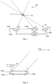
- Fig. 1 is a schematic diagram illustrating a communications network 100 where embodiments presented herein can be applied.
- the communications network 100 could be any of: a cellular communications network (such as Long-Term Evolution (LTE) or New Radio (NR) based cellular communications networks), a wireless local area network (such as WiFi networks), an ultra-wide band (UWB) cellular communications network, a Bluetooth network.
- the communications network 100 comprises a network node 200 operatively connected to three 1D antenna arrays 120a, 120b, 120c.
- the 1D antenna arrays 120a, 120b are placed on one and the same line 140a whereas the 1D antenna array 120c is placed on line 140b which thus does not coincide with line 140a.
- the network node 200 might be any of: a (radio) access network node, a radio base station, a base transceiver station, a node B (NB), an evolved node B (eNB), a gNB, or a dedicated positioning server.
- the 1D antenna arrays 120a, 120b, 120c are configured to provide network access to wireless devices, one of which is identified at reference numeral 110.
- the wireless device 110 might be any of: a portable wireless device, a mobile station, a mobile phone, a handset, a wireless local loop phone, a user equipment (UE), a smartphone, a wearable communication device, a laptop computer, a tablet computer, a wireless sensor, an Internet-of-Things (IoT) device, a network equipped vehicle.
- IoT Internet-of-Things
- Wireless device 110 is assumed to, in an x, y, z-coordinate system, be located at a position ( r x , r y , r z ). According to embodiments disclosed herein, this position is to be determined by the network node 200 based on angle-of-arrival values ⁇ 1 , ⁇ 2 , ⁇ 3 of the 1D antenna arrays 120a, 120b, 120c, where ⁇ n is the angle-of-arrival value of the n:th 1D antenna array.
- Fig. 2 schematically illustrates how an angle-of-arrival value can be obtained at antenna array 120a having two antenna elements 130a, 130b.
- each of the antenna arrays 120a, 120b, 120c might have a plurality of antenna elements 130a, 130b.
- Fig. 2 is shown the calculation of the zenith angle ⁇ ', i.e., the angle to a surface perpendicular to the 1D antenna array 120a.
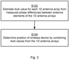
- Fig. 3 is a flowchart illustrating embodiments of methods for position determination of a wireless device 110.
- the methods are performed by the network node 200.
- the methods are advantageously provided as computer programs 1220.
- the herein disclosed embodiments are based on estimating the angle-of-arrival for the 1D antenna arrays 120a, 120b, 120c, given the measured phase differences from the antenna elements in the 1D antenna arrays 120a, 120b, 120c.
- the network node 200 is configured to perform step S102: S102: The network node 200 estimates a respective angle-of-arrival value for each of at least three 1D antenna arrays 120a, 120b, 120c.
- the respective angle-of-arrival values are estimated from measured phase differences between antenna elements 130a, 130b per 1D antenna array 120a, 120b, 120c for a signal communicated between the wireless device 110 and the at least three 1D antenna arrays 120a, 120b, 120c.
- the antenna elements 130a, 130b of each 1D antenna array 120a, 120b, 120c are arranged along a respective line. At least two of the lines are non-coincident with respect to each other.
- the phase of a signal communicated with the wireless device 110 is thus collected at all antenna elements 130a, 130b.
- the collected phase measurements are the relative phase differences between the antenna elements 130a, 130b within an antenna array 120a, 120b, 120c, as illustrated in Fig. 2 .
- the network node 200 uses angle-of-arrival estimates from at least three different 1D antenna array locations to determine the position of the wireless device 110 .
- the network node 200 is configured to perform step S104: S104: The network node 200 determines the position of the wireless device 110 by combining the angle-of-arrival values from the at least three 1D antenna arrays 120a, 120b, 120c.
- This method thus enables the position of the wireless device 110 to be determined if the different 1D antenna arrays 120a, 120b, 120c used for the position estimation are placed on lines where at least two of the lines are non-coincident with respect to each other.
- each angle-of-arrival estimate gives rise to a cone on which the position of the wireless device 110 is located.
- a cone will hereinafter be referred to as an angle-of-arrival-cone.
- the angle-of-arrival cone for a given 1D antenna array can be defined using the orientation of that given 1D antenna array as the symmetry axis and the angle-of-arrival as half of the apex angle.
- Each of the estimated angle-of-arrival values might thus define a half-apex angle of a respective cone, where each cone has its apex centred at a respective one of the 1D antenna arrays 120a, 120b, 120c.
- determining the position of the wireless device 110 in step S104 then equals identifying a position where all the cones intersect. Since the angle-of-arrival values define the half-apex angle of the cones, it is the lateral surfaces of the cones that intersect.
- the angle-of-arrival cone can thus be defined using the orientation of the antenna array as symmetry axis and the angle-of-arrival as half of the apex angle.
- the line along which the antenna elements 130a, 130b of one of the 1D antenna arrays 120a, 120b, 120c are arranged defines a symmetry axis for this one of the 1D antenna arrays 120a, 120b, 120c, and half of an apex angle of the symmetry axis defines the cone for this one of the 1D antenna arrays 120a, 120b, 120c.
- the position of the wireless device 110 can be determined using the intersection of at least three angle-of-arrival cones, one for each of the 1D antenna arrays 120a, 120b, 120c. As illustrated in Fig. 4 , this is equivalent to, for at least one of the 1D antenna arrays 120a, 120b, 120c, finding an unknown angle ⁇ around the axis of rotation of the antenna array and the distance from the antenna array to the wireless device 110, given that the angle ⁇ for this at least one of the 1D antenna arrays is already known.
- Fig. 4 schematically illustrates the angle-of-arrival cone 410 seen from an antenna array 120a comprising two antenna elements 130a, 130b. The angle-of-arrival cone 410 defines possible positions of the wireless device 110.
- determining the position of the wireless device 110 in step S104 involves, for at least one of the 1D antenna arrays 120a, 120b, 120c, determining an angle ⁇ around the symmetry axis and determining the distance between the wireless device 110 and this at least one of the 1D antenna arrays 120a, 120b, 120c.
- the intersection of two angle-of-arrival cones 410, 510, one for a respective 1D antenna array, will give a circle, or ellipsis, 520 on which the wireless device 110 is located.
- the position and orientation of two 1D antenna arrays are shown with arrows P 1 and P 2 and the true position of the wireless device 110 is marked by a cross. All possible positions of the wireless device 110 are on the ellipsis 520 defined by the intersection of the two angle-of-arrival cones 410, 510. A third measurement is thus needed to determine where on the ellipsis the true position of the wireless device 110 can be found.
- Fig. 6 illustrates, according to a first example, the intersection of three angle-of-arrival cones, one for each pair of 1D antenna arrays 120a, 120b, 120c, in terms of a lines, on which the position of the wireless device 110 is located.
- the position and orientation of each 1D antenna array are shown with arrows P 1 , P 2 and P 3 in the figure and the true position of the wireless device 110 is marked by a cross.
- the orientation of the 1D antenna array at position P 3 is perpendicular to the 1D antenna arrays at positions P 1 and P 2 .
- the angle-of-arrival cone for the 1D antenna array located at position P 1 is shown to avoid cluttering.
- Ellipsis 520 marks the intersection between the angle-of-arrival cones for the 1D antenna arrays located at positions P 1 and P 2 .
- Line 610 marks the intersection between the angle-of-arrival cones for the 1D antenna arrays located at positions P 1 and P 3 .
- Line 620 marks the intersection between the angle-of-arrival cones for the 1D antenna arrays located at positions P 2 and P 3 .
- Fig. 7 illustrates, according to a second example, the intersection of three angle-of-arrival cones, one for each pair of 1D antenna arrays 120a, 120b, 120c, in terms of lines 610, 620, on which the position of the wireless device 110 is located.
- the position and orientation of each 1D antenna array are shown with arrows P 1 , P 2 and P 3 in the figure and the true position of the wireless device 110 is marked by a cross.
- the 1D antenna arrays at positions P 1 and P 2 are on one and the same lines whereas the 1D antenna array at position P 3 is not on the same line as the 1D antenna arrays at positions P 1 and P 2 .
- the angle-of-arrival cone 410 for the 1D antenna array located at position P 1 is shown to avoid cluttering.
- Lines 710, 720, 730 marks the intersection between the angle-of-arrival cones for the 1D antenna arrays.
- two distinct possible positions of the wireless device 110 can be determined. That is, in some embodiments there are two positions at which all the cones intersect, and the position of the wireless device 110 is determined by selecting one of the two positions.
- One of the two possible positions might be highly improbable in a practical implementation and can thus be disregarded.
- each of the two positions might be associated with a respective probability value for being the position of the wireless device 110, and the position with highest probability value is selected. This could be the case where the 1D antenna arrays 120a, 120b, 120c are arranged to provide network access to wireless devices in a confined, or in other ways well-defined, region or space.
- One such example could be where the 1D antenna arrays 120a, 120b, 120c are arranged to provide network access to wireless devices in an indoor location and where the position of a wireless device corresponding to an outdoor location thus could be disregarded. Additional angle-of-arrival information from a fourth 1D antenna array may also be utilized to resolve this ambiguity.
- r ( r x , r y , r z ) defines the position of the wireless device 110
- p n is the position of the n:th 1D antenna array
- p ⁇ n is the unit vector describing the orientation of the n:th 1D antenna array
- ⁇ n is the angle-of-arrival measurement from the n:th 1D antenna array.
- the nonlinear system of equations is analytically solved.
- the antenna elements 130a, 130b of the first and second of the 1D antenna arrays 120a, 120b, 120c are arranged along the x-axis and the antenna elements 130a, 130b of the third of the 1D antenna arrays 120a, 120b, 120c are arranged along the y -axis in this x, y, z -coordinate system.
- the nonlinear system of equations is numerically and iteratively solved.
- the position of the wireless device 110 can be determined based on an initial guess of the position of the wireless device 110, and where the position is updated by calculating the direction and distance from one position guess to the next guess which minimizes the error of the position estimate.
- the position of the wireless device 110 is iteratively determined using gradient descent by, for each of the 1D antenna arrays 120a, 120b, 120c and for each current iteratively determined position of the wireless device 110, determining an angle error as difference between an angle-of-arrival value calculated for the current iteratively determined position and the estimated angle-of-arrival value. That is, for each 1D antenna array, based on an initial position estimate, the error ⁇ n of the angle-of-arrival value can be calculated as the difference between the measured angle ⁇ n and the angle corresponding to the current position estimate.
- the shortest vector which eliminates ⁇ n that is, taking the shortest step to the surface of the cone corresponding to antenna array n) is then calculated.
- a new position estimate is calculated by adding these vectors corresponding to all the 1D antenna arrays to the previous position estimate. The process is then repeated until convergence is reached, or a fixed number of iterations have been made.
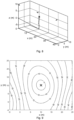
- Fig. 8 shows an example where the position of the wireless device 110 is iteratively determined using gradient descent.
- the position and orientation of the 1D antenna arrays are marked with arrows, the true position of the wireless device 110 is marked with a cross and the estimated position at each iteration is marked with dots (starting at the origin as the initial guess) connected by lines.
- the nonlinear system of equations is solved using brute force.
- the nonlinear system of equations might be solved by testing a set of solutions, each corresponding to a respective position of the wireless device 110, and selecting one of the solutions according to a minimum error criterion.
- a minimum error criterion When using brute force, different possible positions of the wireless device 110 are tested and the one with the smallest error, according to some metric, is assumed to be the correct position.
- the root mean square of the angle errors can be used as metric.
- the angle error is the difference between the (theoretical) angle ⁇ * that would have been observed by the 1D antenna arrays if the wireless device 110 had been located in the tested positions and the estimated angle at the different 1D antenna arrays. That is, in some embodiments, each respective position of the wireless device 110 yields a calculated angle-of-arrival value for each of the at least three 1D antenna arrays 120a, 120b, 120c, and the minimum error criterion pertains to a difference between the calculated angle-of-arrival values and the estimated angle-of-arrival values.
- Fig. 9 illustrates, as a contour plot, an example of the root mean square of the angle errors for different tested positions of the wireless device 110 and where the true position of the wireless device 110 is marked with a cross.
- the numbers on each height curve in the contour plot correspond to the root mean square of the angle errors to three antenna arrays in degrees.
- the result in Fig. 9 assumes knowledge of the height of the wireless device. If the height is not known, the brute force process can be repeated for different values of the height.
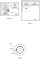
- Fig. 10 schematically illustrates, in terms of a number of functional units, the components of a network node 200 according to an embodiment.
- Processing circuitry 210 is provided using any combination of one or more of a suitable central processing unit (CPU), multiprocessor, microcontroller, digital signal processor (DSP), etc., capable of executing software instructions stored in a computer program product 1210 (as in Fig. 12 ), e.g. in the form of a storage medium 230.
- the processing circuitry 210 may further be provided as at least one application specific integrated circuit (ASIC), or field programmable gate array (FPGA).
- ASIC application specific integrated circuit
- FPGA field programmable gate array
- the processing circuitry 210 is configured to cause the network node 200 to perform a set of operations, or steps, as disclosed above.
- the storage medium 230 may store the set of operations
- the processing circuitry 210 may be configured to retrieve the set of operations from the storage medium 230 to cause the network node 200 to perform the set of operations.
- the set of operations may be provided as a set of executable instructions.
- the processing circuitry 210 is thereby arranged to execute methods as herein disclosed.
- the storage medium 230 may also comprise persistent storage, which, for example, can be any single one or combination of magnetic memory, optical memory, solid state memory or even remotely mounted memory.
- the network node 200 may further comprise a communications interface 220 at least configured for communications with other entities, functions, nodes, and devices of the communications network 100, such as the 1D antenna arrays 120a, 120b, 120c.
- the communications interface 220 may comprise one or more transmitters and receivers, comprising analogue and digital components.
- the processing circuitry 210 controls the general operation of the network node 200 e.g.
- network node 200 by sending data and control signals to the communications interface 220 and the storage medium 230, by receiving data and reports from the communications interface 220, and by retrieving data and instructions from the storage medium 230.
- Other components, as well as the related functionality, of the network node 200 are omitted in order not to obscure the concepts presented herein.
- Fig. 11 schematically illustrates, in terms of a number of functional modules, the components of a network node 200 according to an embodiment.
- the network node 200 of Fig. 11 comprises a number of functional modules; an estimate module 210a configured to perform step S102, and a determine module 210b configured to perform step S104.
- the network node 200 of Fig. 11 may further comprise a number of optional functional modules, such as represented by functional module 210c.
- each functional module 210a-210c may in one embodiment be implemented only in hardware and in another embodiment with the help of software, i.e., the latter embodiment having computer program instructions stored on the storage medium 230 which when run on the processing circuitry makes the network node 200 perform the corresponding steps mentioned above in conjunction with Fig 11 .
- modules 210a-210c may be implemented by the processing circuitry 210, possibly in cooperation with the communications interface 220 and/or the storage medium 230.
- the processing circuitry 210 may thus be configured to from the storage medium 230 fetch instructions as provided by a functional module 210a-210c and to execute these instructions, thereby performing any steps as disclosed herein.
- the network node 200 is collocated with at least one of the 1D antenna arrays 120a, 120b, 120c. In some examples, at least one of the 1D antenna arrays 120a, 120b, 120c is collocated with another network node, and the measured phase difference for this at least one of the 1D antenna arrays 120a, 120b, 120c is obtained from this another network node. In some examples, the network node 200 is implemented in, or acts as, a positioning server.
- the network node 200 may be provided as a standalone device or as a part of at least one further device.
- the network node 200 may be provided in a node of the radio access network or in a node of the core network.
- functionality of the network node 200 may be distributed between at least two devices, or nodes. These at least two nodes, or devices, may either be part of the same network part (such as the radio access network or the core network) or may be spread between at least two such network parts.
- instructions that are required to be performed in real time may be performed in a device, or node, operatively closer to the cell than instructions that are not required to be performed in real time.
- a first portion of the instructions performed by the network node 200 may be executed in a first device, and a second portion of the of the instructions performed by the network node 200 may be executed in a second device; the herein disclosed embodiments are not limited to any particular number of devices on which the instructions performed by the network node 200 may be executed.
- the methods according to the herein disclosed embodiments are suitable to be performed by a network node 200 residing in a cloud computational environment. Therefore, although a single processing circuitry 210 is illustrated in Fig. 10 the processing circuitry 210 may be distributed among a plurality of devices, or nodes. The same applies to the functional modules 210a-210c of Fig. 11 and the computer program 1220 of Fig. 12 .
- Fig. 12 shows one example of a computer program product 1210 comprising computer readable storage medium 1230.
- a computer program 1220 can be stored, which computer program 1220 can cause the processing circuitry 210 and thereto operatively coupled entities and devices, such as the communications interface 220 and the storage medium 230, to execute methods according to embodiments described herein.
- the computer program 1220 and/or computer program product 1210 may thus provide means for performing any steps as herein disclosed.
- the computer program product 1210 is illustrated as an optical disc, such as a CD (compact disc) or a DVD (digital versatile disc) or a Blu-Ray disc.
- the computer program product 1210 could also be embodied as a memory, such as a random access memory (RAM), a read-only memory (ROM), an erasable programmable read-only memory (EPROM), or an electrically erasable programmable read-only memory (EEPROM) and more particularly as a non-volatile storage medium of a device in an external memory such as a USB (Universal Serial Bus) memory or a Flash memory, such as a compact Flash memory.
- the computer program 1220 is here schematically shown as a track on the depicted optical disk, the computer program 1220 can be stored in any way which is suitable for the computer program product 1210.
Landscapes
- Physics & Mathematics (AREA)
- Engineering & Computer Science (AREA)
- General Physics & Mathematics (AREA)
- Radar, Positioning & Navigation (AREA)
- Remote Sensing (AREA)
- Mobile Radio Communication Systems (AREA)
- Probability & Statistics with Applications (AREA)
Claims (12)
- Procédé de détermination de position d'un dispositif sans fil (110), le procédé étant réalisé par un nœud de réseau (200), le procédé comprenant :l'estimation (S102) d'une valeur d'angle d'arrivée respective pour chacun de trois réseaux d'antennes unidirectionnelles (120a, 120b, 120c) à des positions (x_1,0,0), (x_2,0,0) et (x_3,0,0) dans un système de coordonnées (x,y,z), à partir de différences de phases mesurées entre des éléments d'antennes (130a, 130b) par réseau d'antennes unidirectionnelles (120a, 120b, 120c) pour un signal communiqué entre le dispositif sans fil (110) et les trois réseaux d'antennes unidirectionnelles (120a, 120b, 120c), dans lequel les éléments d'antennes d'un premier et d'un deuxième des réseaux d'antennes unidirectionnelles sont agencés le long de l'axe x et les éléments d'antenne d'un troisième des réseaux d'antennes unidirectionnelles sont agencés le long de l'axe y dans ledit système de coordonnées (x,y,z) ; etla détermination (S104) de la position du dispositif sans fil (110) en combinant les valeurs d'angle d'arrivée à partir des trois réseaux d'antennes unidirectionnelles (120a, 120b, 120c), et dans lequel la détermination implique la résolution d'un système non linéaire d'équations définies comme suit :


 dans lequel (rx ,ry ,rz ) est la position du dispositif sans fil, et θ 1, θ 2 et θ 3 sont les valeurs d'angle d'arrivée estimées des trois réseaux d'antennes unidirectionnelles.
 - Procédé selon la revendication 1, dans lequel chacune des valeurs d'angle d'arrivée estimées définit un demi-angle au sommet d'un cône respectif, où chaque cône a son sommet centré au niveau de l'un respectif des réseaux d'antennes unidirectionnelles (120a, 120b, 120c), et dans lequel la détermination de la position du dispositif sans fil (110) équivaut à l'identification d'une position d'intersection de tous les cônes.
- Procédé selon la revendication 2, dans lequel la ligne le long de laquelle les éléments d'antennes (130a, 130b) de l'un des réseaux d'antennes unidirectionnelles (120a, 120b, 120c) sont agencés définit un axe de symétrie pour ledit un des réseaux d'antennes unidirectionnelles (120a, 120b, 120c), et dans lequel un demi-angle au sommet de l'axe de symétrie définit le cône pour ledit un des réseaux d'antennes unidirectionnelles (120a, 120b, 120c).
- Procédé selon la revendication 3, dans lequel la détermination de la position du dispositif sans fil (110) implique, pour au moins l'un des réseaux d'antennes unidirectionnelles (120a, 120b, 120c), la détermination d'un angle autour de l'axe de symétrie et la détermination d'une distance entre le dispositif sans fil (110) et ledit au moins un des réseaux d'antennes unidirectionnelles (120a, 120b, 120c).
- Procédé selon l'une quelconque des revendications 2 à 4, dans lequel il y a deux positions d'intersection de tous les cônes, et dans lequel la position du dispositif sans fil (110) est déterminée par la sélection de l'une des deux positions.
- Procédé selon la revendication 5, dans lequel chacune des deux positions est associée à une valeur de probabilité respective d'être la position du dispositif sans fil (110), et dans lequel la position avec la valeur de probabilité la plus élevée est sélectionnée.
- Procédé selon l'une quelconque des revendications précédentes, dans lequel le nœud de réseau (200) est colocalisé avec au moins l'un des réseaux d'antennes unidirectionnelles (120a, 120b, 120c).
- Procédé selon l'une quelconque des revendications précédentes, dans lequel au moins l'un des réseaux d'antennes unidirectionnelles (120a, 120b, 120c) est colocalisé avec un autre nœud de réseau, et dans lequel la différence de phase mesurée pour ledit au moins un des réseaux d'antennes unidirectionnelles (120a, 120b, 120c) est obtenue à partir dudit autre nœud de réseau.
- Nœud de réseau (200) de détermination de position d'un dispositif sans fil (110), le nœud de réseau (200) comprenant une circuiterie de traitement (210), la circuiterie de traitement étant configurée pour amener le nœud de réseau (200) à :estimer une valeur d'angle d'arrivée respective pour chacun de trois réseaux d'antennes unidirectionnelles (120a, 120b, 120c) à des positions (x_1,0,0), (x_2,0,0) et (x_3,0,0) dans un système de coordonnées (x,y,z), à partir de différences de phases mesurées entre des éléments d'antennes (130a, 130b) par réseau d'antennes unidirectionnelles (120a, 120b, 120c) pour un signal communiqué entre le dispositif sans fil (110) et les trois réseaux d'antennes unidirectionnelles (120a, 120b, 120c), dans lequel les éléments d'antennes d'un premier et d'un deuxième des réseaux d'antennes unidirectionnelles sont agencés le long de l'axe x et les éléments d'antenne d'un troisième des réseaux d'antennes unidirectionnelles sont agencés le long de l'axe y dans ledit système de coordonnées (x,y,z) ; etdéterminer la position du dispositif sans fil (110) en combinant les valeurs d'angle d'arrivée à partir des trois réseaux d'antennes unidirectionnelles (120a, 120b, 120c), et dans lequel la détermination implique la résolution d'un système non linéaire d'équations définies comme suit :


 dans lequel (rx ,ry ,rz ) est la position du dispositif sans fil, et θ 1, θ 2 et θ 3 sont les valeurs d'angle d'arrivée estimées des trois réseaux d'antennes unidirectionnelles.
 - Nœud de réseau (200) selon la revendication 9, étant en outre configuré pour réaliser le procédé selon l'une quelconque des revendications 2 à 8.
- Programme d'ordinateur (1220) de détermination de position d'un dispositif sans fil (110), le programme d'ordinateur comprenant un code d'ordinateur qui, lorsqu'il est exécuté sur une circuiterie de traitement (210) d'un nœud de réseau (200), amène le nœud de réseau (200) à :estimer (S102) une valeur d'angle d'arrivée respective pour chacun de trois réseaux d'antennes unidirectionnelles (120a, 120b, 120c) à des positions (x_1,0,0), (x_2,0,0) et (x_3,0,0) dans un système de coordonnées (x,y,z), à partir de différences de phases mesurées entre des éléments d'antennes (130a, 130b) par réseau d'antennes unidirectionnelles (120a, 120b, 120c) pour un signal communiqué entre le dispositif sans fil (110) et les trois réseaux d'antennes unidirectionnelles (120a, 120b, 120c), dans lequel les éléments d'antennes d'un premier et d'un deuxième des réseaux d'antennes unidirectionnelles sont agencés le long de l'axe x et les éléments d'antenne d'un troisième des réseaux d'antennes unidirectionnelles sont agencés le long de l'axe y dans ledit système de coordonnées (x,y,z) ; etdéterminer (S104) la position du dispositif sans fil (110) en combinant les valeurs d'angle d'arrivée à partir des trois réseaux d'antennes unidirectionnelles (120a, 120b, 120c), et dans lequel la détermination implique la résolution d'un système non linéaire d'équations définies comme suit :


 dans lequel (rx ,ry ,rz ) est la position du dispositif sans fil, et θ 1, θ 2 et θ 3 sont les valeurs d'angle d'arrivée estimées des trois réseaux d'antennes unidirectionnelles.
 - Produit programme d'ordinateur (1210) comprenant un programme d'ordinateur (1220) selon la revendication 11, et un support de stockage lisible par ordinateur (1230) sur lequel le programme d'ordinateur est stocké.
Applications Claiming Priority (1)
| Application Number | Priority Date | Filing Date | Title |
|---|---|---|---|
| PCT/SE2020/050874 WO2022060265A1 (fr) | 2020-09-18 | 2020-09-18 | Détermination de position de dispositif sans fil |
Publications (2)
| Publication Number | Publication Date |
|---|---|
| EP4214529A1 EP4214529A1 (fr) | 2023-07-26 |
| EP4214529B1 true EP4214529B1 (fr) | 2025-05-21 |
Family
ID=72744822
Family Applications (1)
| Application Number | Title | Priority Date | Filing Date |
|---|---|---|---|
| EP20786091.7A Active EP4214529B1 (fr) | 2020-09-18 | 2020-09-18 | Détermination de position de dispositif sans fil |
Country Status (3)
| Country | Link |
|---|---|
| US (1) | US12566237B2 (fr) |
| EP (1) | EP4214529B1 (fr) |
| WO (1) | WO2022060265A1 (fr) |
Families Citing this family (1)
| Publication number | Priority date | Publication date | Assignee | Title |
|---|---|---|---|---|
| EP4533130A1 (fr) * | 2022-05-24 | 2025-04-09 | Huawei Technologies Co., Ltd. | Dispositif sans fil et procédé pour améliorer la détermination de l'emplacement d'un dispositif utilisateur |
Citations (1)
| Publication number | Priority date | Publication date | Assignee | Title |
|---|---|---|---|---|
| US9658314B2 (en) * | 2012-03-02 | 2017-05-23 | Nokomis, Inc. | System and method for geo-locating and detecting source of electromagnetic emissions |
Family Cites Families (8)
| Publication number | Priority date | Publication date | Assignee | Title |
|---|---|---|---|---|
| US9995817B1 (en) * | 2015-04-21 | 2018-06-12 | Lockheed Martin Corporation | Three dimensional direction finder with one dimensional sensor array |
| US10333633B2 (en) * | 2017-05-10 | 2019-06-25 | Telefonaktiebolaget Lm Ericsson (Publ) | Angle of arrival estimation in a radio communications network |
| EP3631998A1 (fr) * | 2017-06-02 | 2020-04-08 | Telefonaktiebolaget LM Ericsson (publ) | Estimation d'angle d'arrivée dans un réseau de communication radio |
| US11143735B2 (en) * | 2018-12-21 | 2021-10-12 | Silicon Laboratories, Inc. | Pseudo-spectrum averaging for angle of arrival detection |
| EP4071507B1 (fr) * | 2019-12-26 | 2026-02-11 | Shenzhen Yinwang Intelligent Technologies Co., Ltd. | Procédé et dispositif de mesure d'angle d'arrivée |
| JP7768132B2 (ja) * | 2020-08-13 | 2025-11-12 | 株式会社ソシオネクスト | 推定方法および推定装置 |
| US11841447B2 (en) * | 2021-01-06 | 2023-12-12 | Samsung Electronics Co., Ltd. | 3D angle of arrival capability in electronic devices with adaptability via memory augmentation |
| US12072427B2 (en) * | 2021-12-17 | 2024-08-27 | The Boeing Company | Antennas for producing a variable phase response, angle-of-arrival sensors and methods for determining angle of arrival |
-
2020
- 2020-09-18 WO PCT/SE2020/050874 patent/WO2022060265A1/fr not_active Ceased
- 2020-09-18 EP EP20786091.7A patent/EP4214529B1/fr active Active
- 2020-09-18 US US18/245,732 patent/US12566237B2/en active Active
Patent Citations (1)
| Publication number | Priority date | Publication date | Assignee | Title |
|---|---|---|---|---|
| US9658314B2 (en) * | 2012-03-02 | 2017-05-23 | Nokomis, Inc. | System and method for geo-locating and detecting source of electromagnetic emissions |
Also Published As
| Publication number | Publication date |
|---|---|
| US20230358850A1 (en) | 2023-11-09 |
| EP4214529A1 (fr) | 2023-07-26 |
| US12566237B2 (en) | 2026-03-03 |
| WO2022060265A1 (fr) | 2022-03-24 |
Similar Documents
| Publication | Publication Date | Title |
|---|---|---|
| US11824272B2 (en) | In-field millimeter-wave phased array radiation pattern estimation and validation | |
| US11991734B2 (en) | Fingerprinting enhancement with multi-band AoA measurements | |
| EP3544323B1 (fr) | Procédé permettant de déterminer un retard de canal, procédé de localisation et dispositif associé | |
| López-Pastor et al. | Wi-Fi RTT-based active monopulse RADAR for single access point localization | |
| EP2975892B1 (fr) | Terminal mobile et dispositif et procédé de localisation | |
| US20180227711A1 (en) | Method and system for device positioning utilizing distributed transceivers with array processing | |
| EP2362236A1 (fr) | Procédé et appareil d'évaluation d'angle d'arrivée | |
| EP3793277B1 (fr) | Procédé et appareil de positionnement de terminal, et support de stockage | |
| US9660740B2 (en) | Signal strength distribution establishing method and wireless positioning system | |
| US20140256352A1 (en) | Method for measuring position of user terminal | |
| JP7315349B2 (ja) | 位置推定装置、及び位置推定方法 | |
| US20250097889A1 (en) | Method and apparatus of positioning for accomodating wireless-environment change | |
| Meles et al. | Measurement based performance evaluation of drone self-localization using AoA of cellular signals | |
| EP4214529B1 (fr) | Détermination de position de dispositif sans fil | |
| US20240155537A1 (en) | Methods for positioning a wireless device, a related wireless node and a related location network node | |
| WO2019090527A1 (fr) | Procédé et appareil de positionnement en intérieur utilisant une antenne reconfigurable | |
| Bao et al. | A 5G NR millimeter-wave-based AoD positioning field experiment | |
| KR20180117346A (ko) | 5g 기지국의 빔스캔을 이용한 위치측정시스템 및 방법 | |
| Wang et al. | ARPAP: A novel antenna-radiation-pattern-aware power-based positioning in RF system | |
| US20230417865A1 (en) | Communication device and method of operation | |
| WO2020091637A1 (fr) | Manipulation de directions de balayage de faisceau de récepteur d'un réseau d'antennes | |
| WO2024141150A1 (fr) | Positionnement d'ue sur la base d'une puissance reçue de signal de référence | |
| EP4305440A1 (fr) | Détermination d'orientation d'un dispositif sans fil |
Legal Events
| Date | Code | Title | Description |
|---|---|---|---|
| STAA | Information on the status of an ep patent application or granted ep patent |
Free format text: STATUS: UNKNOWN |
|
| STAA | Information on the status of an ep patent application or granted ep patent |
Free format text: STATUS: THE INTERNATIONAL PUBLICATION HAS BEEN MADE |
|
| PUAI | Public reference made under article 153(3) epc to a published international application that has entered the european phase |
Free format text: ORIGINAL CODE: 0009012 |
|
| STAA | Information on the status of an ep patent application or granted ep patent |
Free format text: STATUS: REQUEST FOR EXAMINATION WAS MADE |
|
| 17P | Request for examination filed |
Effective date: 20230418 |
|
| AK | Designated contracting states |
Kind code of ref document: A1 Designated state(s): AL AT BE BG CH CY CZ DE DK EE ES FI FR GB GR HR HU IE IS IT LI LT LU LV MC MK MT NL NO PL PT RO RS SE SI SK SM TR |
|
| DAV | Request for validation of the european patent (deleted) | ||
| DAX | Request for extension of the european patent (deleted) | ||
| GRAP | Despatch of communication of intention to grant a patent |
Free format text: ORIGINAL CODE: EPIDOSNIGR1 |
|
| STAA | Information on the status of an ep patent application or granted ep patent |
Free format text: STATUS: GRANT OF PATENT IS INTENDED |
|
| INTG | Intention to grant announced |
Effective date: 20250204 |
|
| GRAS | Grant fee paid |
Free format text: ORIGINAL CODE: EPIDOSNIGR3 |
|
| GRAA | (expected) grant |
Free format text: ORIGINAL CODE: 0009210 |
|
| STAA | Information on the status of an ep patent application or granted ep patent |
Free format text: STATUS: THE PATENT HAS BEEN GRANTED |
|
| AK | Designated contracting states |
Kind code of ref document: B1 Designated state(s): AL AT BE BG CH CY CZ DE DK EE ES FI FR GB GR HR HU IE IS IT LI LT LU LV MC MK MT NL NO PL PT RO RS SE SI SK SM TR |
|
| REG | Reference to a national code |
Ref country code: GB Ref legal event code: FG4D |
|
| REG | Reference to a national code |
Ref country code: CH Ref legal event code: EP |
|
| REG | Reference to a national code |
Ref country code: DE Ref legal event code: R096 Ref document number: 602020051695 Country of ref document: DE |
|
| REG | Reference to a national code |
Ref country code: IE Ref legal event code: FG4D |
|
| REG | Reference to a national code |
Ref country code: NL Ref legal event code: FP |
|
| PG25 | Lapsed in a contracting state [announced via postgrant information from national office to epo] |
Ref country code: PT Free format text: LAPSE BECAUSE OF FAILURE TO SUBMIT A TRANSLATION OF THE DESCRIPTION OR TO PAY THE FEE WITHIN THE PRESCRIBED TIME-LIMIT Effective date: 20250922 Ref country code: FI Free format text: LAPSE BECAUSE OF FAILURE TO SUBMIT A TRANSLATION OF THE DESCRIPTION OR TO PAY THE FEE WITHIN THE PRESCRIBED TIME-LIMIT Effective date: 20250521 Ref country code: ES Free format text: LAPSE BECAUSE OF FAILURE TO SUBMIT A TRANSLATION OF THE DESCRIPTION OR TO PAY THE FEE WITHIN THE PRESCRIBED TIME-LIMIT Effective date: 20250521 |
|
| PGFP | Annual fee paid to national office [announced via postgrant information from national office to epo] |
Ref country code: DE Payment date: 20250929 Year of fee payment: 6 |
|
| REG | Reference to a national code |
Ref country code: LT Ref legal event code: MG9D |
|
| PG25 | Lapsed in a contracting state [announced via postgrant information from national office to epo] |
Ref country code: NO Free format text: LAPSE BECAUSE OF FAILURE TO SUBMIT A TRANSLATION OF THE DESCRIPTION OR TO PAY THE FEE WITHIN THE PRESCRIBED TIME-LIMIT Effective date: 20250821 Ref country code: GR Free format text: LAPSE BECAUSE OF FAILURE TO SUBMIT A TRANSLATION OF THE DESCRIPTION OR TO PAY THE FEE WITHIN THE PRESCRIBED TIME-LIMIT Effective date: 20250822 |
|
| PG25 | Lapsed in a contracting state [announced via postgrant information from national office to epo] |
Ref country code: PL Free format text: LAPSE BECAUSE OF FAILURE TO SUBMIT A TRANSLATION OF THE DESCRIPTION OR TO PAY THE FEE WITHIN THE PRESCRIBED TIME-LIMIT Effective date: 20250521 |
|
| PGFP | Annual fee paid to national office [announced via postgrant information from national office to epo] |
Ref country code: NL Payment date: 20250926 Year of fee payment: 6 |
|
| PG25 | Lapsed in a contracting state [announced via postgrant information from national office to epo] |
Ref country code: BG Free format text: LAPSE BECAUSE OF FAILURE TO SUBMIT A TRANSLATION OF THE DESCRIPTION OR TO PAY THE FEE WITHIN THE PRESCRIBED TIME-LIMIT Effective date: 20250521 |
|
| PGFP | Annual fee paid to national office [announced via postgrant information from national office to epo] |
Ref country code: GB Payment date: 20250929 Year of fee payment: 6 |
|
| PG25 | Lapsed in a contracting state [announced via postgrant information from national office to epo] |
Ref country code: HR Free format text: LAPSE BECAUSE OF FAILURE TO SUBMIT A TRANSLATION OF THE DESCRIPTION OR TO PAY THE FEE WITHIN THE PRESCRIBED TIME-LIMIT Effective date: 20250521 |
|
| PG25 | Lapsed in a contracting state [announced via postgrant information from national office to epo] |
Ref country code: RS Free format text: LAPSE BECAUSE OF FAILURE TO SUBMIT A TRANSLATION OF THE DESCRIPTION OR TO PAY THE FEE WITHIN THE PRESCRIBED TIME-LIMIT Effective date: 20250821 |
|
| PG25 | Lapsed in a contracting state [announced via postgrant information from national office to epo] |
Ref country code: IS Free format text: LAPSE BECAUSE OF FAILURE TO SUBMIT A TRANSLATION OF THE DESCRIPTION OR TO PAY THE FEE WITHIN THE PRESCRIBED TIME-LIMIT Effective date: 20250921 |
|
| PG25 | Lapsed in a contracting state [announced via postgrant information from national office to epo] |
Ref country code: LV Free format text: LAPSE BECAUSE OF FAILURE TO SUBMIT A TRANSLATION OF THE DESCRIPTION OR TO PAY THE FEE WITHIN THE PRESCRIBED TIME-LIMIT Effective date: 20250521 |
|
| REG | Reference to a national code |
Ref country code: AT Ref legal event code: MK05 Ref document number: 1797180 Country of ref document: AT Kind code of ref document: T Effective date: 20250521 |
|
| PG25 | Lapsed in a contracting state [announced via postgrant information from national office to epo] |
Ref country code: SM Free format text: LAPSE BECAUSE OF FAILURE TO SUBMIT A TRANSLATION OF THE DESCRIPTION OR TO PAY THE FEE WITHIN THE PRESCRIBED TIME-LIMIT Effective date: 20250521 Ref country code: DK Free format text: LAPSE BECAUSE OF FAILURE TO SUBMIT A TRANSLATION OF THE DESCRIPTION OR TO PAY THE FEE WITHIN THE PRESCRIBED TIME-LIMIT Effective date: 20250521 Ref country code: AT Free format text: LAPSE BECAUSE OF FAILURE TO SUBMIT A TRANSLATION OF THE DESCRIPTION OR TO PAY THE FEE WITHIN THE PRESCRIBED TIME-LIMIT Effective date: 20250521 |
|
| PG25 | Lapsed in a contracting state [announced via postgrant information from national office to epo] |
Ref country code: CZ Free format text: LAPSE BECAUSE OF FAILURE TO SUBMIT A TRANSLATION OF THE DESCRIPTION OR TO PAY THE FEE WITHIN THE PRESCRIBED TIME-LIMIT Effective date: 20250521 |
|
| PG25 | Lapsed in a contracting state [announced via postgrant information from national office to epo] |
Ref country code: EE Free format text: LAPSE BECAUSE OF FAILURE TO SUBMIT A TRANSLATION OF THE DESCRIPTION OR TO PAY THE FEE WITHIN THE PRESCRIBED TIME-LIMIT Effective date: 20250521 |
|
| PG25 | Lapsed in a contracting state [announced via postgrant information from national office to epo] |
Ref country code: SK Free format text: LAPSE BECAUSE OF FAILURE TO SUBMIT A TRANSLATION OF THE DESCRIPTION OR TO PAY THE FEE WITHIN THE PRESCRIBED TIME-LIMIT Effective date: 20250521 |
|
| PG25 | Lapsed in a contracting state [announced via postgrant information from national office to epo] |
Ref country code: IT Free format text: LAPSE BECAUSE OF FAILURE TO SUBMIT A TRANSLATION OF THE DESCRIPTION OR TO PAY THE FEE WITHIN THE PRESCRIBED TIME-LIMIT Effective date: 20250521 |
|
| REG | Reference to a national code |
Ref country code: DE Ref legal event code: R097 Ref document number: 602020051695 Country of ref document: DE |
|
| PG25 | Lapsed in a contracting state [announced via postgrant information from national office to epo] |
Ref country code: RO Free format text: LAPSE BECAUSE OF FAILURE TO SUBMIT A TRANSLATION OF THE DESCRIPTION OR TO PAY THE FEE WITHIN THE PRESCRIBED TIME-LIMIT Effective date: 20250521 |
|
| PLBE | No opposition filed within time limit |
Free format text: ORIGINAL CODE: 0009261 |
|
| STAA | Information on the status of an ep patent application or granted ep patent |
Free format text: STATUS: NO OPPOSITION FILED WITHIN TIME LIMIT |
|
| REG | Reference to a national code |
Ref country code: CH Ref legal event code: L10 Free format text: ST27 STATUS EVENT CODE: U-0-0-L10-L00 (AS PROVIDED BY THE NATIONAL OFFICE) Effective date: 20260402 |
|
| 26N | No opposition filed |
Effective date: 20260224 |