EP4214905B1 - Système d'automatisation à structure maître-esclave, distributeur et procédé de transmission de télégrammes - Google Patents
Système d'automatisation à structure maître-esclave, distributeur et procédé de transmission de télégrammes Download PDFInfo
- Publication number
- EP4214905B1 EP4214905B1 EP21794542.7A EP21794542A EP4214905B1 EP 4214905 B1 EP4214905 B1 EP 4214905B1 EP 21794542 A EP21794542 A EP 21794542A EP 4214905 B1 EP4214905 B1 EP 4214905B1
- Authority
- EP
- European Patent Office
- Prior art keywords
- transmitting
- receiving device
- distributor
- telegrams
- master unit
- Prior art date
- Legal status (The legal status is an assumption and is not a legal conclusion. Google has not performed a legal analysis and makes no representation as to the accuracy of the status listed.)
- Active
Links
Images


Classifications
-
- H—ELECTRICITY
- H04—ELECTRIC COMMUNICATION TECHNIQUE
- H04L—TRANSMISSION OF DIGITAL INFORMATION, e.g. TELEGRAPHIC COMMUNICATION
- H04L12/00—Data switching networks
- H04L12/28—Data switching networks characterised by path configuration, e.g. LAN [Local Area Networks] or WAN [Wide Area Networks]
- H04L12/40—Bus networks
- H04L12/40006—Architecture of a communication node
-
- H—ELECTRICITY
- H04—ELECTRIC COMMUNICATION TECHNIQUE
- H04L—TRANSMISSION OF DIGITAL INFORMATION, e.g. TELEGRAPHIC COMMUNICATION
- H04L12/00—Data switching networks
- H04L12/28—Data switching networks characterised by path configuration, e.g. LAN [Local Area Networks] or WAN [Wide Area Networks]
- H04L12/40—Bus networks
- H04L12/40169—Flexible bus arrangements
- H04L12/40176—Flexible bus arrangements involving redundancy
- H04L12/40202—Flexible bus arrangements involving redundancy by using a plurality of master stations
-
- H—ELECTRICITY
- H04—ELECTRIC COMMUNICATION TECHNIQUE
- H04L—TRANSMISSION OF DIGITAL INFORMATION, e.g. TELEGRAPHIC COMMUNICATION
- H04L12/00—Data switching networks
- H04L12/28—Data switching networks characterised by path configuration, e.g. LAN [Local Area Networks] or WAN [Wide Area Networks]
- H04L12/40—Bus networks
- H04L12/40169—Flexible bus arrangements
- H04L12/40176—Flexible bus arrangements involving redundancy
- H04L12/40195—Flexible bus arrangements involving redundancy by using a plurality of nodes
-
- H—ELECTRICITY
- H04—ELECTRIC COMMUNICATION TECHNIQUE
- H04L—TRANSMISSION OF DIGITAL INFORMATION, e.g. TELEGRAPHIC COMMUNICATION
- H04L12/00—Data switching networks
- H04L12/28—Data switching networks characterised by path configuration, e.g. LAN [Local Area Networks] or WAN [Wide Area Networks]
- H04L12/40—Bus networks
- H04L2012/4026—Bus for use in automation systems
-
- H—ELECTRICITY
- H04—ELECTRIC COMMUNICATION TECHNIQUE
- H04L—TRANSMISSION OF DIGITAL INFORMATION, e.g. TELEGRAPHIC COMMUNICATION
- H04L12/00—Data switching networks
- H04L12/28—Data switching networks characterised by path configuration, e.g. LAN [Local Area Networks] or WAN [Wide Area Networks]
- H04L12/42—Loop networks
- H04L2012/421—Interconnected ring systems
-
- H—ELECTRICITY
- H04—ELECTRIC COMMUNICATION TECHNIQUE
- H04L—TRANSMISSION OF DIGITAL INFORMATION, e.g. TELEGRAPHIC COMMUNICATION
- H04L69/00—Network arrangements, protocols or services independent of the application payload and not provided for in the other groups of this subclass
- H04L69/40—Network arrangements, protocols or services independent of the application payload and not provided for in the other groups of this subclass for recovering from a failure of a protocol instance or entity, e.g. service redundancy protocols, protocol state redundancy or protocol service redirection
Definitions
- the invention relates to an automation system with a master-slave structure and a method for telegram transmission in such an automation system.
- Serial network systems are often used in manufacturing and automation technology, in which the decentralized devices of machine peripherals such as I/O modules, measuring transducers, drives, valves and operator terminals communicate with automation, engineering or visualization systems. All participants are networked with each other via a serial data bus, preferably via a field bus, with the data exchange via the data bus usually being carried out on the basis of the master-slave principle in the form of data packets, also referred to as telegrams.
- the master units on the data bus usually the control devices, have bus access authorization and determine the data transfer on the data bus.
- the slave units on the data bus usually machine peripheral devices, do not have bus access authorization, i.e. H. They may only acknowledge received telegrams or transmit telegrams to a master unit upon request.
- the telegrams also known as frames, are made up of control data and user data.
- the Ethernet standard is often used as the protocol for controlling data exchange on the data bus, which enables telegrams with a length of up to 1500 bytes at a high transmission speed of up to 10 Gbit/sec.
- the data bus of the master-slave automation system often has a ring structure in which the individual slave units on the transmission path are connected to form a ring, with each participant being connected to two neighbors and the first and last participants in the ring being connected to the master unit .
- the telegrams are transmitted in one direction starting from the master unit via its transmitting unit to the first connected slave unit and from there to the next until the last slave unit in the ring in the data transmission direction is reached, and then from the last slave unit. Unit returns to the receiving unit of the master unit.
- Errors in the automation system that must be overcome without impairment include, in addition to errors in the telegrams, the failure of a participant in the transmission path or an interruption in the transmission path, for example by physically cutting the transmission medium.
- a master-slave automation system is known in which the data bus has a double ring topology with two separate communication paths connecting a master unit to slave units.
- the master unit generates two telegrams with an identical user data block, which circulate in opposite directions on the two communication paths.
- the two separate communication paths in the two slave units adjacent to the interruption point are short-circuited.
- the EP 3 072 262 B1 describes an extension of a master-slave automation system in which two master units are provided on the data bus. If one master unit fails, a second replacement master unit can then take over communication. In order to be able to carry out such a switchover, the second replacement master unit requires additional hardware, which is why the replacement master unit cannot be implemented in any industrial PC or can only be implemented with additional effort.
- an automation system with a redundant master unit, at least one slave unit and a ring-shaped data bus is known, with either the first or the second master unit being connected to the ring-shaped data bus by a switch.
- the object of the present invention is to provide an automation system with a master-slave structure and a method for telegram transmission in such an automation system, which enable an improved reconfiguration of the telegram transmission path when the master unit changes operation.
- An automation system with a plurality of participants and a ring-shaped data bus includes, as participants, a first master unit, a first distributor, a second master unit, a second distributor and at least one slave unit.
- the first master unit and the second master unit each have a control device that is designed to generate telegrams, the telegrams each comprising a control data block with an individual identifier and a user data block.
- the first distributor has a switching device, a first transmitting/receiving device and a second transmitting/receiving device, the switching device being connected to the control device of the first master unit and the first and second transmitting/receiving devices in order to, after evaluating in to transmit the telegrams between the control device of the first master unit, the first transmitting/receiving device and the second transmitting/receiving device based on the individual identifiers contained in the telegrams on the basis of the first switching regulation defined in the switching device.
- the second distributor has a switching device, a first transmitting/receiving device and a second transmitting/receiving device, the switching device being connected to a control device of the second master unit and the first and second transmitting/receiving devices in order to, after evaluating the in the individual identifier contained in the telegrams on the basis of a second switching regulation defined in the switching device to transmit the telegrams between the control device of the second master unit, the first transmitting / receiving device and the second transmitting / receiving device.
- the first transmitting/receiving devices of the first distributor and the second distributor are connected via the ring-shaped data bus in order to transmit telegrams between the first transmitting/receiving devices of the first distributor and the second distributor. Further the second transmitting/receiving devices of the first distributor and the second distributor are connected via the ring-shaped data bus in order to transmit telegrams between the second transmitting/receiving devices of the first distributor and the second distributor.
- the slave unit has a processing unit, a first transmitting/receiving device and a second transmitting/receiving device, wherein the processing unit is connected to the first transmitting/receiving device and the second transmitting/receiving device and is designed to transmit between the first -/receiving device and the second transmitting/receiving device to process exchanged telegrams, and wherein the first transmitting/receiving device is connected to the data bus in order to exchange telegrams on the data bus with the first transmitting/receiving device of the first distributor, the second transmitting -/receiving device is connected to the data bus in order to exchange telegrams on the data bus with the first transmitting/receiving device of the second distributor.
- the first switching control defined in the switching device of the first distributor forwards telegrams received from the first master unit to the first transmitting/receiving device. Furthermore, the first switching control defined in the switching device of the first distributor forwards telegrams received by the second transmitting/receiving device to the first master unit. The second switching control defined in the switching device of the second distributor also forwards first telegrams received from the first sending/receiving device to the second sending/receiving device.
- the second switching control defined in the switching device of the second distributor forwards telegrams received from the second master unit to the second transmitting/receiving device. Furthermore, the second switching control defined in the switching device of the second distributor forwards telegrams received from the first transmitting/receiving device to the second master unit. The first switching control defined in the switching device of the first distributor also forwards telegrams received from the second sending/receiving device to the first sending/receiving device.
- This embodiment of the master-slave automation system makes it possible, with little additional hardware effort, for the telegram transmission path to be automatically reconfigured in real time when switching between two operating modes, for example due to the failure of the master unit currently responsible for controlling the automation system.
- the fault tolerance functionality is provided by the two, additionally in the automation system provided, distributor or through their pre-stored switching regulations, which automatically switch from one master unit to the other master unit.
- the data bus may include a first communication path and a second communication path, wherein the first transmitting/receiving devices of the first distributor and the second distributor are respectively connected to the first communication path and the second communication path of the data bus in order to transmit telegrams on the first communication path and the second communication path of the data bus.
- the first transmitting/receiving device of the slave unit is connected to the first communication path and the second communication path of the data bus in order to exchange telegrams on the first communication path and the second communication path of the data bus with the first transmitting/receiving device of the first distributor.
- the second transmitting/receiving device of the slave unit is connected to the first communication path and the second communication path of the data bus in order to exchange telegrams on the first communication path and the second communication path of the data bus with the first transmitting/receiving device of the second distributor.
- the control device of the first master unit In the first operating mode, the control device of the first master unit generates first telegrams with a first identifier and second telegrams with a second identifier, which have an identical user data block.
- the first switching control defined in the switching device of the first distributor then forwards first telegrams received from the first master unit to the first transmitting/receiving device and second telegrams received from the first master unit to the second transmitting/receiving device.
- the first switching control defined in the switching device of the first distributor forwards second telegrams received from the first transmitting/receiving device and first telegrams received from the second transmitting/receiving device to the first master unit.
- the second switching control defined in the switching device of the second distributor forwards second telegrams received from the second sending/receiving device to the first sending/receiving device.
- the second switching control defined in the switching device of the second distributor forwards first telegrams received from the first transmitting/receiving device to the second transmitting/receiving device.
- the control device of the second master unit In the second operating mode, the control device of the second master unit generates third telegrams with a third identifier and fourth telegrams with a fourth identifier, which have an identical user data block.
- the second switching regulation defined in the switching device of the second distributor routes the data received from the second master unit third telegrams to the second transmitting/receiving device and fourth telegrams received from the second master unit to the first transmitting/receiving device.
- the second switching control defined in the switching device of the second distributor forwards third telegrams received from the first transmitting/receiving device and fourth telegrams received from the second transmitting/receiving device to the second master unit.
- the first switching control defined in the switching device of the first distributor forwards third telegrams received from the second sending/receiving device to the first sending/receiving device.
- the first switching control defined in the switching device of the first distributor forwards fourth telegrams received from the first sending/receiving device to the second sending/receiving device.
- telegram transmission can be switched to the other communication path, with the two additional distributors provided in the master-slave automation system or their pre-stored switching regulations ensuring that telegrams are transmitted on both communication paths even when switching between the two master units circulate the telegram transmission path correctly.
- the slave unit can further have a coupling device which is designed to short-circuit the first communication path and the second communication path in the first transmitter/receiver device when a data transmission error occurs to the subscriber connected to the first transmitter/receiver device and to close when a data transmission error occurs to short-circuit the first communication path and the second communication path in the second transmitter/receiver device for the subscriber connected to the second transmitter/receiver device.
- a coupling device which is designed to short-circuit the first communication path and the second communication path in the first transmitter/receiver device when a data transmission error occurs to the subscriber connected to the first transmitter/receiver device and to close when a data transmission error occurs to short-circuit the first communication path and the second communication path in the second transmitter/receiver device for the subscriber connected to the second transmitter/receiver device.
- the first switching control defined in the switching device forwards first telegrams received from the first transmitting/receiving device and second telegrams received from the second transmitting/receiving device to the first master unit. Furthermore, the second switching control defined in the switching device of the second distributor forwards second telegrams received from the first sending/receiving device to the second sending/receiving device.
- the first switching control defined in the switching device of the first distributor forwards third telegrams received from the first transmitting/receiving device to the second transmitting/receiving device. Furthermore, the in the Second switching control determined by the switching device forwards third telegrams received from the second transmitting / receiving device and fourth telegrams received from the first transmitting / receiving device to the second master unit.
- the second switching control defined in the switching device of the second distributor forwards telegrams received from the first transmitting/receiving device in addition to the second master unit.
- This procedure ensures that both master units, including the replacement master unit, always receive the entire telegram traffic, so that when switching from the main master unit to the replacement master unit, the replacement master unit can continue the control process in the automation system based on the current status without delay.
- the control device of the second master unit can then monitor the standard operating mode in order to start the second operating mode if an interruption of the standard operating mode is detected.
- This procedure ensures that if the main master unit fails, the backup master unit starts operating without delay in order to continue the control process in the automation system without interruption.
- the control device of the second master unit can be further designed to transmit the telegrams received in the second operating mode from the control device of the second master unit to the control device of the first master unit when the standard operating mode is resumed.
- This procedure means that the standard operating mode can be resumed without delay, for example after the main master unit has been resolved.
- networks are used to connect distributed field devices on a sensor/actuator level with a control level.
- the automation systems also called fieldbus systems, usually have a serial bus to which the network participants are connected.
- Manufacturers use various fieldbus concepts that differ in terms of the connection structure, bus access and the standardized fieldbus protocol.
- the network protocol determines how data exchange between participants in the network should be carried out.
- the network protocol determines the rules and formats for the communication behavior of the participants.
- the message structure determined by the network protocol contains all the information important for data exchange, such as sender and recipient, message type, message size and checksum to trace an error-free transmission. This information is prefixed to the payload in the message as a header or attached as a trailer.
- the Ethernet protocol has established itself as a communication standard for short-range networks, especially in automation systems.
- the Ethernet protocol divides the data to be transmitted into so-called frames, the structure of which is in the IEEE 802.3 standard is fixed.
- the actual Ethernet frame is preceded by a preamble and a start bit, the so-called Start Frame Delimiter SFD. This is then followed by the actual Ethernet telegram.
- the Ethernet telegram consists of a header section, the header, a user data block and an end section, the trailer.
- the header starts with a 6-byte field for the destination address, which is followed by another 6-byte field with the source address.
- a further 6-byte field, the so-called tag field can then follow with additional control data in the header, which in particular contains prioritization information.
- the header ends with a 2-byte field, the so-called type field, which provides information about the protocol with which the data in the user data block is to be processed.
- the user data block following the header can have a length of 1500 bytes, although larger data blocks can also be permitted in various Ethernet protocol extensions.
- the payload data block can be terminated by the so-called PAD field in order to guarantee the specified minimum length of the Ethernet frame.
- the trailer which has a 6-byte field with a checksum, is connected to the user data block.
- a CRC calculation is performed over the bit sequence and the checksum is appended to the data block.
- the recipient performs the same calculation after receiving it. If the received checksum does not match the self-calculated checksum, the recipient assumes that the transmission was incorrect. The Ethernet telegram is then discarded.
- Ethernet standard in industrial automation makes it possible to provide real-time solutions.
- Real-time capable fieldbus systems based on the Ethernet standard include PROFINET, EtherCAT, Powerlink or SERCOS III.
- the fieldbus protocol used is displayed as a type field in the header of the Ethernet frame.
- Ethernet In addition to the Ethernet standard, other fieldbus protocols, such as CANopen, Interbus or Profibus, can also be used in automation systems.
- CANopen Interbus
- Profibus Profibus
- Automation systems are usually operated with a master-slave structure.
- the master unit in the automation system is the controller, which has bus access authorization and can output data to the fieldbus.
- the slave units in the fieldbus system are the field devices, such as I/O devices, valves, drives, sensors, transmitters, etc. They do not have bus access authorization and are only allowed to acknowledge received data and transmit data when requested by the master unit.
- control via an automation system is usually carried out in such a way that the master unit preferably carries out control processes cyclically in order to generate output data for this and/or other slave units based on input data from slave units .
- the master unit After completing a control process cycle, the master unit sends the output data in the form of telegrams on the fieldbus, whereby the slave unit can take the output data assigned to the respective slave unit from the telegrams and use this output data to execute a local participant process.
- the data determined by the local subscriber process is then in turn transmitted from the slave unit to the master unit and then used by the master unit as input data for the next control process cycle.
- Automation systems with a master-slave structure are often designed in such a way that the individual slave units are connected to form a chain via the transmission medium, with each slave unit having two neighbors, the first and the last slave unit in the chain the master unit are connected, resulting in a ring structure.
- the data transfer on the data bus takes place in one direction starting from the master unit to the first neighboring slave unit and from there to the next to the last slave unit and then back to the master unit.
- master units In the automation system with a plurality of participants connected via a data bus, several master units can be integrated that are assigned to the different operating modes. Such a configuration is particularly useful in order to be able to continue data communication without interruption if the master unit fails due to the control process in the master-slave automation system.
- the second master unit serves as a replacement master unit in the master-slave automation system, which then carries out telegram traffic with the slave units after the main master unit fails.
- the The two master units are each connected via a distributor with a data bus designed as a ring structure.
- the two distributors each have a switching device that is connected to a control device of the assigned master unit.
- the control device of the master unit is designed to generate telegrams, each of which includes a control data block with an individual identifier and a user data block.
- the two distributors also each have a first transmitting/receiving device and a second transmitting/receiving device, which are connected to the switching device in the distributor.
- the first transmitting/receiving device and the second transmitting/receiving device of the distributor are constructed identically.
- the identification of the transmitting/receiving device as the first transmitting/receiving device and the second transmitting/receiving device of the distributor are selected such that a first or second switching control set in the switching device of the first or second distributor is received from the assigned first or second master unit always forwards generated telegrams to the first transmitting/receiving device in order to output the telegrams on the data bus connected to the first transmitting/receiving device.
- the master unit and the associated distributor can be designed as separate components.
- a telegram transmission device is connected between the control device of the master unit and the switching device of the distributor, consisting of a transmitting/receiving device assigned to the master unit and a transmitting/receiving device assigned to the distributor, which are connected to one another via a data bus .
- the transmitting/receiving device assigned to the master unit is connected to the control device of the master unit via an internal data connection.
- a conventional master unit can be used as a master unit without additional hardware, which is implemented on an industrial PC, for example.
- the distributor is then implemented as an additional component for the master unit, with the transmitting/receiving device assigned to the distributor being connected to the switching device of the distributor with an internal data connection.
- the master unit and the distributor into a single component, with the control device of the master unit and the switching device of the distributor then being directly connected to one another via an internal data connection.
- the component can, for example, be implemented as an application-specific integrated circuit (ASIC).
- the first transmitting/receiving devices and the second transmitting/receiving devices of the two distributors are each connected to one another via the ring-shaped data bus in order to transmit telegrams on the data bus.
- the slave units are connected to the ring-shaped data bus between the two distributors.
- Each slave unit has a processing unit, a first transmitting/receiving device and a second transmitting/receiving device, the processing unit being connected to the first transmitting/receiving device and the second transmitting/receiving device and being designed to transmit between the first -/receiving device and the second sending/receiving device to process exchanged telegrams.
- the first transmitting/receiving device and the second transmitting/receiving device of the slave unit are each connected to the Ring-shaped data bus connected in order to exchange telegrams on the data bus with the first transmitting / receiving device or second transmitting / receiving device of the first or second distributor.
- the first transmitting/receiving device of at least one slave unit is connected to the first transmitting/receiving device of the first distributor via the data bus in order to receive telegrams on the data bus from the first transmitting/receiving device of the first distributor .
- the second transmitting/receiving device of the at least one slave unit is connected to the first transmitting/receiving device of the second distributor via the data bus in order to transmit telegrams after a data exchange with the processing unit as they pass through the slave unit Forward the data bus to the first transmitter/receiver device of the second distributor.
- slave units it is possible for slave units to be arranged in the data bus both between the first transmitting/receiving devices of the two distributors and between the second transmitting/receiving devices of the two distributors.
- the first switching control defined in the switching device of the first distributor forwards telegrams received from the first master unit to the first transmitting/receiving device. Furthermore, the first switching control defined in the switching device of the first distributor forwards telegrams received from the second transmitting/receiving device to the first master unit. The second switching control defined in the switching device of the second distributor also forwards first telegrams received from the first sending/receiving device to the second sending/receiving device.
- the second switching control defined in the switching device of the second distributor forwards telegrams received from the second master unit to the second transmitting/receiving device. Furthermore, the second switching control defined in the switching device of the second distributor forwards telegrams received from the first transmitting/receiving device to the second master unit. The first switching control defined in the switching device of the first distributor also forwards telegrams received from the second sending/receiving device to the first sending/receiving device.
- the two additional distributors provided in the automation system or their pre-stored switching regulations ensure that, regardless of whether the telegrams in the automation system are generated by the first master unit or the second master unit, the telegrams circulate in the data bus and are sent by everyone to the Data bus connected slave units.
- master-slave automation systems In order to ensure a high level of error tolerance, especially in the case of route errors in the automation system, i.e. H. In the event of failure of entire transmission sections with slave units, for example due to a line break, master-slave automation systems often have a second replacement communication path that connects the master units with the slave units to form a further ring structure.
- the data bus then has a first communication path and a second communication path, wherein the first transmitting/receiving devices of the first distributor and the second distributor are each connected to the first communication path and the second communication path of the data bus in order to transmit telegrams on the first communication path and the second Communication path of the data bus to be transmitted.
- the first transmitting/receiving device of the at least one slave unit is connected to the first communication path and the second communication path of the data bus in order to exchange telegrams on the first communication path and the second communication path of the data bus with the first transmitting/receiving device of the first distributor.
- the second transmitting/receiving device of the slave unit is connected to the first communication path and the second communication path of the data bus in order to exchange telegrams on the first communication path and the second communication path of the data bus with the first transmitting/receiving device of the second distributor.
- the control device of the first master unit In the first operating mode, the control device of the first master unit generates first telegrams with a first identifier and second telegrams with a second identifier, which have an identical user data block.
- the first switching control defined in the switching device of the first distributor then forwards first telegrams received from the first master unit to the first transmitting/receiving device and second telegrams received from the first master unit to the second transmitting/receiving device.
- the first switching control defined in the switching device of the first distributor forwards second telegrams received from the first transmitting/receiving device and first telegrams received from the second transmitting/receiving device to the first master unit.
- the second switching control defined in the switching device of the second distributor forwards second telegrams received from the second sending/receiving device to the first sending/receiving device.
- the second switching control defined in the switching device of the second distributor forwards first telegrams received from the first transmitting/receiving device to the second transmitting/receiving device.
- the control device of the second master unit In the second operating mode, the control device of the second master unit generates third telegrams with a third identifier and fourth telegrams with a fourth identifier, which have an identical user data block.
- the second switching control defined in the switching device of the second distributor forwards third telegrams received from the second master unit to the second transmitting/receiving device and forwards fourth telegrams received from the second master unit to the first transmitting/receiving device.
- the second switching control defined in the switching device of the second distributor forwards third telegrams received from the first transmitting/receiving device and fourth telegrams received from the second transmitting/receiving device to the second master unit.
- the first switching control defined in the switching device of the first distributor forwards third telegrams received from the second sending/receiving device to the first sending/receiving device.
- the first switching control defined in the switching device of the first distributor forwards fourth telegrams received from the first sending/receiving device to the second sending/receiving device.
- telegram transmission can be switched to the other communication path, with the two additional distributors provided in the master-slave automation system or their pre-stored switching regulations ensuring that telegrams are transmitted on both communication paths even when switching between the two master units circulate the telegram transmission path correctly.
- the fact that the master units always circulate two telegrams with an identical user data block reliably ensures that even if a communication path in the data bus fails, a telegram always passes through all slave units on the data bus and from the processing units in the slave units is interpreted and processed.
- the master unit therefore receives back at least one telegram that has been completely processed by all slave units on the data bus. In the event that both telegrams have been completely processed by all slave units on the data bus, the master unit can reject one of the two telegrams.
- the slave units each further have a coupling device which is designed, in the event of a data transmission error, to the participant connected to the first transmitting/receiving device to short-circuit the first communication path and the second communication path in the first transceiver and, when a data transmission error occurs to the subscriber connected to the second transceiver, to short-circuit the first communication path and the second communication path in the second transceiver.
- the first switching control defined in the switching device forwards first telegrams received from the first transmitting/receiving device and second telegrams received from the second transmitting/receiving device to the first master unit. Furthermore, the second switching control defined in the switching device of the second distributor forwards second telegrams received from the first sending/receiving device to the second sending/receiving device.
- the first switching control defined in the switching device of the first distributor forwards third telegrams received from the first transmitting/receiving device to the second transmitting/receiving device. Furthermore, the second switching control defined in the switching device of the second distributor forwards third telegrams received from the second transmitting/receiving device and fourth telegrams received from the second transmitting/receiving device to the second master unit.
- an automatic reconfiguration of the telegram transmission paths is carried out in the event of a route error on a communication path in the double ring topology.
- the behavior of the participants in the automation system in the case of a reconfiguration does not differ from the behavior in normal operation.
- the automatic reconfiguration by the two additional distributors provided in the master-slave automation system or their pre-stored switching regulations ensures a high level of dynamics during the switching process and thus enables real-time requirements to be met in the automation system.
- the coupling device in the slave unit is designed so that all telegrams both in normal operation and in short-circuit operation, if the coupling device, when a data transmission error occurs, send the first communication path and the second communication path to the subscriber connected to the first or second transceiver device short-circuits in the respective transmitting/receiving device,
- the telegrams always pass through the processing unit of the slave unit once. This ensures that the telegrams can be interpreted and processed by the processing unit of the slave unit.
- the control device of the first or second master unit can also have a counter field set to a predetermined value in the two telegrams with an identical user data block.
- the processing unit of each slave unit then changes the value of the counter field by a predetermined value as the telegram passes through.
- the control device of the first or second master unit evaluates the value of the counter fields of the two telegrams circulated on the data bus in order to determine whether all slave units connected to the data bus have processed the respective telegram. By correlating the values in the counter fields of the two received telegrams, it can also be determined between which slave units a route error has occurred in the communication path of the data bus or whether or where a slave unit has completely failed.
- the evaluation of the counter fields of the two circulating telegrams received on the first and second communication paths is preferably carried out by adding up the counter field values.
- the total value then indicates whether all connected slave units are active, as their number is directly reflected in the total value.
- the fault tolerance of the master-slave automation system is further improved when in read mode, i.e. H. then, when the slave units are to transmit data to the master unit, the two telegrams with the identical user data block circulate in opposite directions on the first and second communication paths, with the slave units writing data into the user data block as the respective telegram passes through.
- the control device of the master unit then ORs the user data blocks of the two telegrams circulated on the first communication path and the second communication path.
- This procedure is used in the master-slave automation system in a simple manner, especially in the case of reconfiguration, when the telegram transmission paths are changed due to a route error by short-circuiting the first communication path and the second communication path in slave units and individual participants are switched to error mode ensure reliable reading operation.
- a combined user data block is generated in which, regardless of how the telegrams are fed back to the master unit via the first and second communication paths, all the data to be transmitted by the slave units is contained.
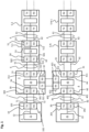
- Fig. 1 shows schematically the possible structure of a fault-tolerant master-slave automation system with a double ring design of the data bus.
- the master-slave automation system has a first master unit 1, hereinafter also referred to as a main master unit, and a second master unit 2, hereinafter also referred to as a replacement master unit, a first distributor 3 second distributor 4 and a plurality of N slave units 5, which are numbered as slave units 5-1, 5-2, ..., 5-N-1, 5-N.
- the main master unit 1 and the replacement master unit 2 have the same structure.
- the main master unit 1 has a transmitting/receiving device 10, also referred to below as Port_P0, which includes a transmitting unit TX 101 and a receiving unit RX 102.
- the master unit 1 contains a control device 11, which is connected to the Port_P0 10 via a data connection 12.
- the replacement master unit 2 has a transmitting/receiving device 20, also referred to below as Port_P0, which includes a transmitting unit TX 201 and a receiving unit RX 202.
- the replacement master unit 2 contains a control device 21, which is connected to the Port_P0 20 via a data connection 22.
- the first distributor 3 and the second distributor 4 are also constructed the same.
- the first distributor 3 has a master transmitter/receiver device 30, hereinafter also referred to as Port_P0, which includes a transmitter unit TX 301 and a receiver unit RX 302, a first transmitter/receiver device 31, hereinafter also referred to as Port_P1, which has a Transmitting unit TX 311 and a receiving unit RX 312, and a second transmitting/receiving device 32, hereinafter also referred to as Port_P2, which comprises a transmitting unit TX 321 and a receiving unit RX 322.
- a switching device 33 is provided, which is connected to Port_P0 30, Port_P1 31 and Port_P2 32 via an internal data connection 34.
- the second distributor 4 has a master transmitter/receiver device 40, hereinafter also referred to as Port_P0, which includes a transmitter unit TX 401 and a receiver unit RX 402, a first transmitter/receiver device 41, hereinafter also referred to as Port_P1, which has a Transmitting unit TX 411 and a receiving unit RX 412, and a second transmitting/receiving device 42, hereinafter also referred to as Port_P2, which comprises a transmitting unit TX 421 and a receiving unit RX 422. Furthermore, a switching device 43 is provided, which is connected to Port_P0 40, Port_P1 41 and Port_P2 42 via an internal data connection 44.
- the master-slave automation system further has a slave data bus 6 with two unidirectional communication paths, which are referred to as the first communication path 61 and the second communication path 62.
- the slave data bus 6 connects the first distributor 3, the slave units 5-1, 5-2, ..., 5-N-1, 5-N and the second distributor 4 to one another in series.
- the first distributor 3 is connected via the transmitting unit TX 311 of Port_P1 31 to the first communication path 61 as a telegram coupling point and via the receiving unit RX 312 of Port_P1 31 to the second communication path 62 as a telegram coupling point.
- the second distributor 4 is connected via the transmitting unit TX 411 of Port_P1 41 to the second communication path 62 as a telegram coupling point and via the receiving unit RX 412 of Port_P1 41 to the first communication path 61 as a telegram coupling point.
- the sending unit TX 321 of the Port_P2 32 of the first distributor 3 is connected via the second communication path 62 to the receiving unit RX 422 of the Port_P2 42 of the second distributor 4. Furthermore, the receiving unit RX 322 of the Port_P2 32 of the first distributor 3 is connected to the transmitting unit TX 421 of the Port_P2 42 of the second distributor 4 via the first communication path 61.
- the Port_P0 10 of the main master unit 1 is connected to the Port_P0 30 of the first distributor 1 via a main data bus 7.
- the sending unit TX 101 of the Port_P0 10 of the main master unit 1 is connected to the receiving unit RX 302 of the Port_P0 30 of the first distributor 3 via a first unidirectional communication path 71.
- the receiving unit RX 102 of the Port_P0 10 of the main master unit 1 is connected to the transmitting unit TX 301 of the Port_P0 30 of the first distributor 3 via a second unidirectional communication path 72.
- the Port_P0 20 of the replacement master unit 2 is connected to the Port_P0 40 of the second distributor 4 via a replacement data bus 8.
- the sending unit TX 201 of the Port_P0 20 of the replacement master unit 2 is connected to the receiving unit RX 402 of the Port_P0 40 of the second distributor 4 via a first unidirectional communication path 81.
- the receiving unit RX 202 of the Port_P0 20 of the replacement master unit 2 is connected to the transmitting unit TX 401 of the Port_P0 40 of the second distributor 4 via a second unidirectional communication path 82.
- the main data bus 7 and the replacement data bus 8 can each be designed as a branch of the slave data bus 6, which in a ring connects the first distributor 3 one after the other with the slave units 5-1, 5-2, ..., 5- N-1, 5-N and the second distributor 4 and then again to the first distributor 3, the two unidirectional communication paths 61, 62 being operated in opposite directions.
- the slave unit 5 points from the main master unit 1 viewed from a first transmitting/receiving device 50, also referred to as Port_P1, for connection to a previous participant, and a second transmitting/receiving device 51, also referred to below as Port_P2, for connecting to the next participant.
- the Port_P1 50 includes a transmitting unit TX 501 and a receiving unit RX 502, the transmitting unit TX 501 of the Port_P1 50 being connected to the second communication path 62 and the receiving unit RX 502 of the Port_P1 50 being connected to the first communication path 61.
- the Port_P2 51 includes a transmitting unit TX 511 and a receiving unit RX 512, the transmitting unit TX 511 of the Port_P1 51 being connected to the first communication path 61 and the receiving unit RX512 of the Port_P1 51 being connected to the second communication path 62.
- a processing device 52 is connected between Port_P1 50 and Port_P2 51 and is connected to Port_P1 50 and Port_P2 51 via an internal data connection 53.
- the processing device 52 includes a telegram processing unit 520 and a coupling device 521, which includes a first changeover switch 5211 and a second changeover switch 5212.
- the first switch 5211 and the second switch 5212 are each designed as 2-1 multiplexers.
- the transmitting unit TX 501 and the receiving unit RX 502 of Port_P1 50, the transmitting unit TX 511 and the receiving unit RX 512 of Port_P2 51, the first changeover switch 5211, the second changeover switch 5212 and the telegram processing unit 520 are interconnected via the internal data connection 53.
- the receiving unit RX 502 of Port_P1 50 is connected to the first input of the first switch 5211 via a data line of the internal data connection 53.
- the second input of the first switch 5211 is connected to the receiving unit RX 512 of Port_P2 51 via a data line of the internal data connection 53.
- the output of the first switch 5211 is connected to the telegram processing unit 520 via a data line of the internal data connection 53.
- the second changeover switch 5212 is connected with its first input to the telegram processing unit 520 via a data line of the internal data connection 53 and with its second input to the receiving unit RX 512 of Port_P2 51 via a data line of the internal data connection 53.
- the output of the second switch 5212 is connected to the transmitting unit TX 501 of Port_P1 50.
- the telegram processing unit 520 is connected to the sending unit TX 511 of the Port_P2 51 via a data line of the internal data connection 53.
- the embodiment of the slave unit 5 shown has the advantage that in each slave unit only a single telegram processing unit has to be provided in the processing device, regardless of whether the coupling device with the changeover switches in the slave unit is in normal operation or in fault mode, in which a short circuit occurs between the first communication path and the second communication path, is always passed through by at least one of the two telegrams with an identical user data block, which circulate in opposite directions on the first communication path or the second communication path of the data bus. In this way, the hardware effort and thus the costs can be reduced.
- the behavior of the slave unit 5 in the event of redundancy i.e. when a route error occurs, does not differ from the behavior in normal operation. At the same time, this ensures a high level of dynamics during the switching process.
- the control device 11 of the main master unit 1 and the replacement master unit 2 have the same structure.
- the main master unit 1 has a transmitting/receiving device 10, also referred to below as Port_P0, which includes a transmitting unit TX 101 and a receiving unit RX 102.
- the master unit 1 contains a control device 11, which is connected to the Port_P0 10 via a data connection 12.
- the replacement master unit 2 has a transmitting/receiving device 20, also referred to below as Port_P0, which includes a transmitting unit TX 201 and a receiving unit RX 202.
- the replacement master unit 2 contains a control device 21, which is connected to the Port_P0 20 via a data connection 22.
- Fig. 1 Master-slave automation system shown is controlled by the main master unit 1 in a first operating mode, which represents the standard operating mode. In a second operating mode, which serves as a replacement operating mode, control is taken over by the replacement master unit 2.
- the control device of the respective master unit in the standard operating mode the control device 11 of the main master unit 1 and in the replacement operating mode the control device 21 of the replacement master unit 2, generates telegrams with an identifier that is used for identification serves the respective master unit.
- the master unit can provide all telegrams generated by the master unit with the same identifier.
- the control device of the master unit that controls the telegram traffic always generates two telegrams with the same user data block, the two telegrams having different identifiers, which, however, each generate the telegrams individually Mark master unit.
- the telegram identifier is preferably entered in the header of the telegram.
- the tag field can be used for additional control data to enter the identifier.
- the telegram identifier can also be contained in the source address of the Ethernet telegram.
- the switching device 33 of the first distributor 3 and the switching device 43 of the second distributor 4 have a first or second switching control, also referred to below as a transfer table.
- the transfer table the telegram identifiers assigned by the main master unit 1 or the replacement master unit 2 are also listed several times, whereby two port identifiers are assigned to each listed telegram identifier, namely the port of the Distributor on which telegrams with the telegram identifier are received, hereinafter also referred to as the reception port, and the port of the distributor on which the telegrams are further sent, hereinafter also referred to as the send port.
- the switching device of the respective distributor detects the telegram identifier and then forwards the telegram to the sending unit TX of the port, which is noted in the transfer table for the telegram identifier and the receiving port as send ports is.
- the transfer table can be stored in a memory of the switching device of the distributor.
- the transfer table can be loaded into the memory of the switching device of the distributor, for example by the master unit assigned to the distributor. It is also possible to program the transfer table directly into the distributor, for example via an externally accessible interface.
- control device 11 of the main master unit 1 generates first telegrams with a first identifier 1 and second telegrams with a second identifier 2, which contain an identical user data block. It is further assumed that the control device 21 provides the replacement master unit 2 with third telegrams with a third identifier 3 and fourth telegrams with a fourth identifier 4, which have an identical user data block.
- Transfer table of the first distributor 3 Telegram identifier Receive port Send port 1 P0 P1 1 P2 P0 1 P1 P0, P2 2 P0 P2 2 P1 P0 2 P2 P0 3 P2 P0, P1 3 P1 P0, P2 4 P1 P0, P2 4 P2 P0 Transfer table of the second distributor 4 Telegram identifier Receive port Send port 1 P1 P0, P2 1 P2 P0 2 P2 P0, P1 2 P1 P1 P0, P2 3 P0 P2 3 P1 P0 3 P2 P1 4 P0 P1 4 P2 P0 4 P1 P0, P2
- the routing with the help of the above transfer tables of the first distributor 3 and the second distributor 4 is ensured automatically and regardless of whether the master-slave automation system is in the standard operating mode from the main master unit 1 or in the replacement operating mode from the Replacement master unit 2 will operate for correct telegram forwarding in the master-slave automation system. This also applies when a route error occurs, i.e. when slave units short-circuit the first communication path 61 and the second communication path 62 of the slave data bus 6 due to an interruption in the slave data bus 6.
- Fig. 1 The telegram transmissions in the master-slave automation system are described below Fig. 1 explained separately for the standard operating mode and the substitute operating mode, whereby the occurrence of a route error is also taken into account for both the standard operating mode and the substitute operating mode.
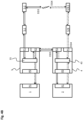
- Fig. 3A shows the standard operating mode in the master-slave automation system according to Fig. 1 , whereby the telegram transmission direction in the communication paths is indicated by arrows.
- a solid line in Fig. 3A the transmission path for the first telegrams sent by the main master unit 1 with the identifier 1 is shown.
- the transmission path for the second telegrams with the identifier 2 sent by the main master unit 1 is shown as a dotted line Fig. 3A registered.
- the first telegram generated by the control device 11 of the main master unit 1 has the identifier 1 and the second telegram generated by the control device 11 of the main master unit 1 has the identifier 2 , which have an identical user data block, are transmitted via the Port_P0 10 on the main data bus 7 to the Port_P0 30 of the first distributor 3.
- the first telegram with the identifier 1 and the second telegram with the identifier 2 can be transmitted serially one after the other via the transmitting unit TX 101.
- the circulation of the first telegram with the identifier 1 starting from the first distributor 3 is explained below: After receipt via Port_P0 30, the first telegram with the identifier 1 is forwarded in the first distributor 3 via the internal data connection 34 to the switching device 33.
- the switching device 33 of the first distributor 3 detects the telegram identifier and routes the telegram using the transfer table of the first distributor 3. For clarification, the section of the transfer table of the first distributor 3 for the forwarding of first telegrams with the identifier 1 is again shown played back in standard operating mode.
- Fig. 3A Transfer table of the first distributor 3 in standard operating mode Telegram identifier Receive port Send port 1 P0 P1 1 P2 P0
- the switching device 33 of the first distributor 3 forwards the first telegram with the identifier 1, which was received on the Port_P0 30, via the internal data connection 34 to the Port_P1 31 of the first distributor 3, which sends the telegram on the first communication path 61 of the slave data bus 6 outputs.
- the first telegram with the identifier 1 passes one after the other through the slave units 5-1 to 5-N arranged on the first communication path 61.
- the first telegram with the identifier 1 is received by Port_P1 50 of the slave unit 5 and forwarded via the internal data connection 53 to the processing device 52 of the slave unit 5.
- the telegram processing unit 520 of the processing device 52 interprets the passing first telegram with the identifier 1 and carries out a data exchange with the useful data block of the telegram.
- the first telegram with the identifier 1 is then transferred via the internal data connection 53 to the Port_P2 51 of the slave unit 5, which further sends the telegram on the first communication path 61.
- the last slave unit 5-N on the first communication path 61 of the slave data bus 6 transmits after processing the first telegram with the identifier 1 to Port_P1 41 of the second distributor 4.
- the first telegram with the identifier 1 in the second distributor 4 is forwarded via the internal data connection 44 to the switching device 43, which routes the telegram based on the transfer table stored in the second distributor 4.
- the section of the transfer table of the second distributor 4 for the forwarding of first telegrams with the identifier 1 in the standard operating mode is shown again.
- Fig. 3A Transfer table of the second distributor 4 in standard operating mode Telegram identifier Receive port Send port 1 P1 P0, P2
- the switching device 43 of the second distributor 4 forwards the first telegram with the identifier 1 to the Port_P0 40 via the internal data connection 44.
- the Port_P0 40 of the second distributor 4 then transmits the first telegram with the identifier 1 via the replacement data bus 8 to the Port_P0 20 of the replacement master unit 2.
- the first telegram with the identifier 1 output via the Port_P2 42 of the second distributor 4 is received by the Port_P2 32 of the first distributor 3 on the first communication path 61 of the slave data bus 6 and by the switching device 33 of the first distributor 3 in accordance with the above excerpt of the transfer -Table of the first distributor 3 is routed via the internal data connection 34 to the Port_P0 30, which transmits the first telegram with the identifier 1 on the main data bus 7 to the Port_P0 10 of the main master unit 1.
- the circulation of the second telegram with the identifier 2 starting from the first distributor 3 is explained below: After receipt via Port_P0 30, the second telegram with the identifier 2 is forwarded in the first distributor 3 via the internal data connection 34 to the switching device 33. The switching device 33 of the first distributor 3 then routes the telegram using the transfer table of the first distributor 3, of which the excerpt of the transfer table of the first distributor 3 for the forwarding of second telegrams with the identifier 2 in the standard operating mode is shown here again is.
- Fig. 3A Transfer table of the first distributor 3 in standard operating mode Telegram identifier Receive port Send port 2 P0 P2 2 P1 P0
- the switching device 33 of the first distributor 3 forwards the second telegram with the identifier 2 to Port_P2 32, which outputs the telegram to the second communication path 62 of the slave data bus 6.
- the second telegram with the identifier 2 is then received by the second distributor 4 on the Port_P2 42 and routed by the switching device 43 of the second distributor 4 according to the transfer table.
- Fig. 3A Transfer table of the second distributor 4 in standard operating mode Telegram identifier Receive port Send port 2 P2 P0, P1
- the second telegram with the identifier 2 received on the Port_P2 42 is routed by the switching device 43 of the second distributor 4 according to the transfer table via the internal data connection 34 to both the Port_P0 40 and the Port_P1 41.
- the Port_P0 40 of the second distributor 4 then transmits the second telegram with the identifier 2 via the replacement data bus 8 to the Port_P0 20 of the replacement master unit 2.
- the second telegram with the identifier 2 is output to the second communication path 62 of the slave data bus 6.
- the second telegram with the identifier 2 passes one after the other through the slave units 5-1 to 5-N arranged on the second communication path 62, with the second telegram with the identifier 2 circulating in the opposite direction to the first telegram with the identifier 1 on the first communication path 61, i.e. from the slave unit 5-N is forwarded via the slave unit 5-N-1 to the slave unit 5-1.
- the second telegram with the identifier 2 is received by Port_P2 51 of the slave unit 5 and forwarded via the internal data connection 53 to the processing device 52 of the slave unit 5. If the slave unit is designed as shown in Fig. 2 is shown, in the standard operating mode only the first telegram with the telegram identifier 1, which circulates on the first communication path 61 of the slave data bus 6, is processed by the telegram processing unit 520 in the processing device 52 of the slave unit 5. The second telegram with the identifier 2, which circulates on the second communication path 62 of the slave data bus 6 in the opposite direction to the first telegram with the identifier 1, is, however, passed through unprocessed by the slave unit 5.
- the first changeover switch 5211 and the second changeover switch 5212 in the coupling device 521 of the processing device 52 are set so that only the first telegram with the identifier 1 received on the first communication path 61 runs via the telegram processing unit 520 of the processing device 52 to be processed.
- the second telegram with the second identifier 2 is transmitted directly from Port_P2 51 to Port_P1 50 by the first changeover switch 5211 and the second changeover switch 5212 in the coupling device 521 on the internal data connection 53.
- the last slave unit 5-1 on the second communication path 62 of the slave data bus 6 transmits the second telegram with the identifier 2 to Port_P1 31 of the first distributor 3.
- the second telegram with the identifier 2 is sent via the internal Data connection 34 is forwarded to the switching device 33 of the first distributor 3, which routes the telegram to Port_P0 30 on the basis of the above transfer table stored in the first distributor 3, from where the second telegram with the Identifier 2 on the main data bus 7 is fed back to Port_P0 10 of the main master unit 1.
- both telegrams are identical in both the control device 11 of the main master unit 1 and in the control device 21 of the replacement master unit 2.
- the control device 11 of the main master unit 1 then sends back the first telegram with the identifier 1, with which all slave units 5-1 to 5-N can exchange data with the user data block of the telegram are further processed.
- the replacement master unit 2 can then switch from the main master unit 1 to the replacement master unit 2, for example, after failure of the main-master unit 1, continue the control process in the master-slave automation system without delay based on the current status.
- Fig. 3B shows the backup operating mode in the master-slave automation system according to Fig. 1 after failure of the main master unit 1, in which the replacement master unit 2 controls the telegram traffic in the master-slave automation system.
- the solid line in Fig. 3B represents the transmission path for the third telegrams with the identifier 3 sent by the replacement master unit 2.
- the transmission path for the fourth telegrams with the identifier 4 sent by the replacement master unit 2 is shown as a dotted line Fig. 3B registered.
- the third telegram generated by the control device 21 of the replacement master unit 2 has the identifier 3 and the fourth telegram generated by the control device 21 of the replacement master unit 2 has the identifier 4 , which have an identical user data block, are transmitted via the Port_P0 10 on the replacement data bus 8 to the Port_P0 40 of the second distributor 4.
- the third telegram with the identifier 3 and the fourth telegram with the identifier 4 can be transmitted serially one after the other from the transmitting unit TX 201 of the Port_P0 20 of the replacement master unit 2.
- the circulation of the third telegram with the identifier 3 starting from the second distributor 4 is explained below: After receipt via Port_P0 40, the third telegram with the identifier 3 is forwarded in the second distributor 4 via the internal data connection 44 to the switching device 43.
- the switching device 43 of the second distributor 4 records the telegram identifier and then routes the telegram using the transfer table of the second distributor 4.
- the section of the transfer table of the second distributor 4 for the forwarding of third telegrams is with the identifier 3 played back in substitute operating mode.
- Fig. 3B Transfer table of the second distributor 4 in replacement operating mode Telegram identifier Receive port Send port 3 P0 P2 3 P1 P0
- the third telegram with the identifier 3 received on the Port_P0 30 of the second distributor 4 is routed by the switching device 43 of the third distributor 4 according to the transfer table via the internal data connection 44 to the Port_P2 42, which receives the telegram on the first communication path 61 of the slave -Data bus 6 to Port_P2 32 of the first distributor 3 transmits.
- the third telegram with the identifier 3 in the first distributor 3 is forwarded via the internal data connection 34 to the switching device 33, which routes the telegram based on the transfer table stored in the first distributor 3 .
- the transfer table of the first distributor 3 for the transmission of third telegrams with the identifier 3 in the replacement operating mode.
- Fig. 3B Transfer table of the first distributor 3 in replacement operating mode Telegram identifier Receive port Send port 3 P2 P0, P1
- the third telegram with the identifier 3 received on Port_P2 32 is forwarded by the switching device 33 of the first distributor 2 via the internal data connection 34 to both Port_P0 30 and Port_P1 31.
- the Port_P0 30 of the first distributor 3 then tries to transmit the third telegram with the identifier 3 via the main data bus 7 to the Port_P0 10 of the main master unit 1. However, since the main master unit 1 has failed, the telegram is not received.
- the third telegram with the identifier 3 is output from Port_P1 31 of the first distributor 3 to the first communication path 61 of the slave data bus 6.
- the third telegram with the identifier 3 passes one after the other through the slave units 5-1 to 5-N arranged on the first communication path 61.
- the third telegram with the identifier 3 is received by Port_P1 50 of the slave unit 5 and forwarded via the internal data connection 53 to the telegram processing unit 520 of the processing device 52, which carries out a data exchange with the useful data block of the telegram.
- the third telegram with the identifier 3 is transferred via the internal data connection 53 to the Port_P2 51 of the slave unit 5, which then sends the telegram on the first communication path 61.
- the third telegram with the identifier 3 in the second distributor 4 is forwarded via the internal data connection 44 to the switching device 43, which routes the telegram to Port_P0 40 on the basis of the above transfer table stored in the second distributor 4.
- the circulation of the fourth telegram with the identifier 4 starting from the second distributor 4 is explained below: After receipt via Port_P0 40, the fourth telegram with the identifier 4 is forwarded in the second distributor 4 via the internal data connection 44 to the switching device 43. The switching device 43 of the second distributor 4 then routes the telegram using the transfer table of the second distributor 4, of which the section of the transfer table of the second distributor 4 for the forwarding of fourth telegrams with the identifier 4 in the replacement operating mode is shown here .
- Fig. 3B Transfer table of the second distributor 4 in replacement operating mode Telegram identifier Receive port Send port 4 P0 P1 4 P2 P0
- the switching device 43 of the second distributor 4 forwards the fourth telegram with the identifier after evaluating the telegram identifier 4 to Port_P1 41, which outputs the telegram on the second communication path 62 of the slave data bus 6.
- the fourth telegram with the identifier 4 passes one after the other through the slave units 5-1 to 5-N arranged in the second communication path 62, with the fourth telegram with the identifier 4 circulating in the opposite direction to the third telegram with the identifier 3 on the first communication path 61 and from the Slave unit 5-N, then to slave unit 5-N-1 to slave unit 5-1.
- the fourth telegram with the identifier 4 is received by Port_P2 51 of the slave unit 5 and forwarded via the internal data connection 53 to the processing device 52 of the slave unit 5. If the slave unit is designed as shown in Fig. 2 is shown, in the replacement operating mode, analogous to the standard operating mode, only the third telegram with the telegram identifier 3, which circulates on the first communication path 61 of the slave data bus 6, is sent by the telegram processing unit 520 of the processing device 52 in the slave Unit 5 processed. The fourth telegram with the identifier 4, which circulates on the second communication path 62 of the slave data bus 6 in the opposite direction to the third telegram with the identifier 3, is, however, passed through unprocessed by the slave unit 5.
- the first changeover switch 5211 and the second changeover switch 5212 in the coupling device 521 of the processing device 52 are set so that only the third telegram received on the first communication path 61 with the identifier 3 is sent via the telegram processing unit 520 of the processing device 54 runs to be processed.
- the fourth telegram with the fourth identifier 4 is transmitted directly from Port_P2 51 to Port_P1 50 by the first switch 5211 and the second switch 5212 on the internal data connection 53.
- the last slave unit 5-1 on the second communication path 62 of the slave data bus 6 transmits the fourth telegram with the identifier 4 to Port_P1 31 of the first distributor 3.
- the fourth telegram with the identifier 4 is then sent via the internal data connection 34 is forwarded to the switching device 33 of the first distributor 3, which routes the telegram based on the transfer table stored in the first distributor.
- Fig. 3B Transfer table of the first distributor 3 in replacement operating mode Telegram identifier Receive port Send port 4 P1 P0, P2
- the fourth telegram with the identifier 4 received on Port_P1 31 is routed by the switching device 33 of the first distributor 3 according to the transfer table via the internal data connection 34 to both Port_P0 30 and Port_P2 32.
- the Port_P0 30 of the first distributor 3 then tries to transmit the fourth telegram with the identifier 4 via the main data bus 7 to the Port_P0 10 of the main master unit 1. However, since the main master unit 1 has failed, the telegram is not received.
- the fourth telegram with the identifier 4 output via the Port_P2 32 of the first distributor 3 is received by the Port_P2 42 of the second distributor 4 on the second communication path 62 of the slave data bus 6 and by the switching device 43 of the second distributor 4 in accordance with the above excerpt of the transfer -Table of the second distributor 4 routed via the internal data connection 44 to the Port_P0 40, which transmits the fourth telegram with the identifier 4 on the replacement data bus 8 to the Port_P0 20 of the replacement master unit 2.
- the feedback third telegram with the identifier 3 is then sent back by the control device 21 of the substitute master unit 2 in the substitute operating mode of the master-slave automation system , with which all slave units 5-1 to 5-N have carried out a data exchange with the user data block of the telegram, is further processed.
- the control device 21 of the replacement master unit 2 in the master-slave automation system is designed to monitor the standard operating mode in which the control device 11 of the main master unit 1 controls the telegram traffic in order to detect a failure of the main -Master unit 1 to enter the replacement operating mode.
- the control device 21 of the replacement master unit 2 can record the telegram traffic without delay, since the control device 21 of the replacement master unit 2 in the standard operating mode is parallel to the main master unit 1 after processing by the slave units 5-1 to 5-N has received the first telegrams with the identifier 1 and is therefore up to date with the current status of the control process.
- the control device 21 of the replacement master unit 2 is then further designed, when switching back to the standard operating mode, when the main master unit 1 is active again, in the replacement operating mode by the control device 21 of the replacement master -Unit 2 received, processed by the slave units 5-1 to 5-N fourth telegrams with the identifier 4 to the control device 11 of the main master unit 1 to transmit.
- the control device 11 of the main master unit 1 can thus seamlessly connect in the standard operating mode to the telegram traffic in the alternative operating mode.
- Fig. 4A shows the standard operating mode in the master-slave automation system according to Fig. 1 , whereby a route error has occurred in slave data bus 6.
- the master-slave automation system has the ability to automatically reconfigure in order to maintain telegram transmission in the automation system.
- the two slave units adjacent to the error point automatically switch to error mode, in which the coupling device 521 in the processing device 52 of the slave unit 5 in the in Fig. 2 shown embodiment short-circuits the first communication path 61 and the second communication path 62 with the aid of the first switch 5211 and the second switch 5212 in order to redirect the telegrams from one communication path to the other communication path.
- the control device 11 of the main-master unit 1 As in the regular standard operating mode of the master-slave automation system, the control device 11 of the main-master unit 1 generates a first telegram with the identifier 1 and a second telegram with the identifier 2, which have an identical user data block, and via the Port_P0 10 on the main data bus 7 is transferred to Port_P0 30 of the first distributor 3.
- a loop-shaped telegram transmission takes place via the first communication path 61 and the second communication path 62 of the slave data bus 6.
- a solid line in Fig. 4A the transmission path for the first telegrams sent by the main master unit 1 with the identifier 1 is shown.
- the transmission path for the second telegrams with the identifier 2 sent by the main master unit 1 is shown as a dotted line Fig. 3A registered.
- Fig. 4A Transfer table of the first distributor 3 in standard operating mode in the event of a route error
- Telegram identifier Receive port Send port 1 P0 P1 1 P2 P0 1 P1 P0, P2
- the first telegram with the identifier 1 is forwarded in the first distributor 3 via the internal data connection 34 to the switching device 33.
- the switching device 33 of the first distributor 3 routes the first telegram with the identifier 1 via the internal data connection 34 to Port_P1 31 of the first distributor 3 according to the transfer table.
- the first telegram with the identifier 1 is then output from Port_P1 31 of the first distributor 3 on the first communication path 61 of the slave data bus 6.
- the first telegram with the identifier 1 passes one after the other through the slave units arranged on the first communication path 61 to the slave unit that is adjacent to the route error.
- the first telegram with the identifier 1 is received by Port_P1 50 of the slave unit 5 and forwarded via the internal data connection 53 to the processing device 52 of the slave unit 5, whose telegram processing unit 520 receives the first telegram with the identifier 1 carries out a data exchange.
- the first telegram with the identifier 1 is then transferred via the internal data connection 53 to the Port_P2 51 of the slave unit 5, which further sends the telegram on the first communication path 61.
- the first telegram with the identifier 1 is returned to Port_P1 50, which is the first, after processing by the telegram processing unit 520 instead of to Port_P2 51 by a corresponding change in the second changeover switch 5212 of the coupling device 521 Telegram with the identifier 1 is output on the second communication path 62.
- the first telegram with the identifier 1 then runs in opposite directions, without being further processed, through the slave units on the second communication path 62 to the first slave unit 5-1.
- the first slave unit 5-1 then transmits the first telegram with the identifier 1 to Port_P1 31 of the first distributor 3.
- the first telegram with the identifier 1 is forwarded via the internal data connection 34 to the switching device 33 of the first distributor 3, which Telegram is routed to both Port_P0 30 and Port_P2 32 based on the above transfer table stored in the first distributor 3.
- the Port_P0 30 of the first distributor 3 transmits the first telegram with the identifier 1 on the main data bus 7 to the Port_P0 10 of the main master unit 1.
- the Port_P2 32 of the first distributor 3 sends the first telegram with the identifier 1 on the first communication path 61 to the Port_P2 42 of the second distributor 4.
- the first telegram with the identifier 1 is sent in the second distributor 4 via the internal data connection 44 to the switching device 43 forwarded, which routes the telegram on the basis of the transfer table stored in the second distributor 4, of which the corresponding section of the transfer table of the second distributor 4 is shown below for the routing of first telegrams with the identifier 1 in the standard operating mode in the event of a route error is reproduced.
- Fig. 4A Transfer table of the second distributor 4 in standard operating mode in the event of a route error Telegram identifier Receive port Send port 1 P2 P0
- the switching device 43 of the second distributor 4 forwards the first telegram with the identifier 1 via the internal data connection 44 to the Port_P0 40.
- the Port_P0 40 of the second distributor 4 then transmits the first telegram with the identifier 1 via the replacement data bus 8 to the Port_P0 20 of the replacement master unit 2.
- the circulation of the second telegram with the identifier 2 starting from the first distributor 3 is explained below: After receipt via Port_P0 30, the second telegram with the identifier 2 is forwarded in the first distributor 3 via the internal data connection 34 to the switching device 33. The switching device 33 of the first distributor 3 then routes the telegram using the transfer table of the first distributor 3, from which again the section of the transfer table of the first distributor 3 for the forwarding of second telegrams with the identifier 2 in the standard operating mode at a Route error is reproduced.
- Fig. 4A Transfer table of the first distributor 3 in standard operating mode in the event of a route error Telegram identifier Receive port Send port 2 P0 P2 2 P1 P0 2 P2 P0
- the switching device 33 of the first distributor 3 forwards the second telegram with the identifier 2 to Port_P2 32, which outputs the telegram to the second communication path 62 of the slave data bus 6.
- the second telegram with the identifier 2 is then received by the second distributor 4 on the Port_P2 42 and routed by the switching device 43 of the second distributor 4 according to the transfer table.
- Fig. 4A Transfer table of the second distributor 4 in standard operating mode in the event of a route error
- the second telegram with the identifier 2 received on the Port_P2 42 is routed by the switching device 43 of the second distributor 4 according to the transfer table via the internal data connection 34 to both the Port_P0 40 and the Port_P1 41.
- the Port_P0 40 of the second distributor 4 then transmits the second telegram with the identifier 2 via the replacement data bus 8 to the Port_P0 20 of the replacement master unit 2.
- the second telegram with the identifier 2 is output to the second communication path 62 of the slave data bus 6.
- the second telegram with the identifier 2 passes one after the other through the slave units arranged on the second communication path 62 to the slave unit that borders the route error, the second telegram with the identifier 2 running in the opposite direction to the first telegram with the identifier 1 on the first communication path 61 , i.e. starting from the slave unit 5-N.
- the second telegram with the identifier 2 is received by the Port_P2 51 of the slave unit 5 and forwarded via the internal data connection 53 to the processing device 52 of the slave unit 5, which receives the second telegram with the identifier 2 by a corresponding setting of the first Switch 5211 and the second switch 5212 in the coupling device 521 are passed on unprocessed to Port_P1 50, which further sends the telegram on the second communication path 62.
- the second telegram with the identifier 2 is forwarded to the telegram processing unit 520 in the processing device 52 instead of to Port_P1 50 by a corresponding change in the first switch 5211 of the coupling device 521, which exchanges data with the user data block of the telegram.
- the telegram is then transferred via the internal data connection 53 to the Port_P2 51 of the slave unit 5, which sends the telegram on the first communication path 61 in the opposite direction to Sends telegram reception direction back to the second distributor 4.
- the second telegram with the identifier 2 then passes one after the other through the slave units arranged on the first communication path 61, with the telegram processing unit 520 in the processing device 52 processing the passing telegram.
- the last slave unit 5-N on the first communication path 61 of the slave data bus 6 transmits the second telegram with the identifier 2 to Port_P1 41 of the second distributor 4.
- the second telegram with the identifier 2 is forwarded in the second distributor 4 via the internal data connection 44 to the switching device 43, which routes the telegram to both Port_P0 40 and Port_P2 42 based on the transfer table stored in the second distributor 4.
- the Port_P0 40 of the second distributor 4 transmits the second telegram with the identifier 2 via the replacement data bus 8 to the Port_P0 20 of the replacement master unit 2.
- the second telegram with the identifier 2 output by the Port_P2 42 of the second distributor 4 on the first communication path 61 of the slave data bus 6 is received by the Port_P2 32 of the first distributor 3 and by the switching device 33 of the first distributor 3 in accordance with the above excerpt of the transfer Table of the first distributor 3 routed via the internal data connection 34 to the Port_P0 30, which transmits the second telegram with the identifier 2 on the main data bus 7 to the Port_P0 10 of the main master unit 1.
- both telegrams are identical in both the control device 11 of the main master unit 1 and in the control device 21 of the replacement master unit 2.
- the control device 11 of the main master unit 1 and the control device 21 of the replacement master unit 2 then OR in the standard operating mode in the event of a route error User data blocks of the first telegram with the identifier 1 and the second telegram with the identifier 2, so that a combined user data block is generated in which, regardless of how the telegrams were fed back via the first and the second communication path, all from the slave units data to be transmitted is included.
- Fig. 4B shows the backup operating mode in the master-slave automation system according to Fig. 1 after failure of the main master unit 1, in which the replacement master unit 2 controls the telegram traffic in the master-slave automation system, whereby a route error has also occurred in the slave data bus 6. If a route error occurs in the slave data bus 6, the two slave units adjacent to the error point automatically switch to error mode, in which the coupling device 521 in the processing device 52 of the slave unit 5 in the in Fig. 2 shown embodiment short-circuits the first communication path 61 and the second communication path 62 with the aid of the first switch 5211 and the second switch 5212 in order to redirect the telegrams from one communication path to the other communication path.
- the control device 21 of the replacement master unit 2 As in the regular replacement operating mode of the master-slave automation system, the control device 21 of the replacement master unit 2 generates a third telegram with the identifier 3 and a fourth telegram with the identifier 4, which have an identical user data block, and via the Port_P0 20 on the replacement data bus 8 is transferred to Port_P0 40 of the second distributor 4.
- a loop-shaped telegram transmission takes place via the first communication path 61 and the second communication path 62 of the slave data bus 6.
- a solid line in Fig. 4B the transmission path for the third telegrams sent by the replacement master unit 2 with the identifier 3 is shown.
- the transmission path for the fourth telegrams with the identifier 4 sent by the replacement master unit 2 is shown as a dotted line Fig. 4B registered.
- Fig. 4B Transfer table of the second distributor 4 in replacement operating mode in the event of a route error
- the third telegram with the identifier 3 is forwarded in the second distributor 4 via the internal data connection 44 to the switching device 43.
- the switching device 43 of the second distributor 4 then routes the telegram using the transfer table to Port_P2 42 of the second distributor 4, which transmits the third telegram with the identifier 3 on the first communication path 61 of the slave data bus 6 to Port_P2 32 of the first distributor 3 .
- the third telegram with the identifier 3 is forwarded in the first distributor 3 via the internal data connection 34 to the switching device 33, which routes the telegram on the basis of the transfer table stored in the first distributor 3.
- the transfer table of the first distributor 3 for the transmission of third telegrams with the identifier 3 in the replacement operating mode in the event of a route error.
- Fig. 4B Transfer table of the first distributor 3 in replacement operating mode in the event of a route error
- the third telegram with the identifier 3 received on Port_P2 32 is forwarded by the switching device 33 of the first distributor 3 via the internal data connection 34 to both Port_P0 30 and Port_P1 31.
- the Port_P0 40 of the first distributor 3 then tries to transmit the third telegram with the identifier 3 via the main data bus 7 to the Port_P0 10 of the main master unit 1. However, since the main master unit 1 has failed, the telegram is not received.
- the third telegram with the identifier 3 is output from Port_P1 31 of the first distributor 3 to the first communication path 61 of the slave data bus 6.
- the third telegram with the identifier 3 passes through those arranged on the first communication path 61 one after the other Slave units up to the slave unit adjacent to the route error.
- the third telegram with the identifier 3 is received by Port_P1 50 of the slave unit 5 and forwarded via the internal data connection 53 to the processing device 52 of the slave unit 5, whose telegram processing unit 520 receives the third telegram with the identifier 3 carries out a data exchange.
- the third telegram with the identifier 3 is then transferred via the internal data connection 53 to the Port_P2 51 of the slave unit 5, which then sends the telegram on the first communication path 61.
- the third telegram with the identifier 3 is returned to Port_P1 50 after processing by the processing unit 520 instead of to Port_P2 51 by a corresponding changeover in the second changeover switch 5212 of the coupling device 521, which carries the third telegram the identifier 3 on the second communication path 62 outputs.
- the third telegram with the identifier 3 then runs in opposite directions, without being further processed, through the slave units on the second communication path 62 to the first slave unit 5-1.
- the first slave unit 5-1 then transmits the third telegram with the identifier 3 to Port_P1 31 of the first distributor 3.
- the third telegram with the identifier 3 is forwarded via the internal data connection 34 to the switching device 33 of the first distributor 3, which Telegram is routed to Port_P0 30 and Port_P2 32 based on the above transfer table stored in the first distributor 3.
- the Port_P0 40 of the first distributor 3 then tries to transmit the third telegram with the identifier 3 again via the main data bus 7 to the Port_P0 10 of the main master unit 1. However, since the main master unit 1 has failed, the telegram is not received.
- the Port_P2 40 of the first distributor 3 sends the third telegram with the identifier 3 on the first communication path 61 to the Port_P2 42 of the second distributor 4.
- the third telegram with the identifier 3 is sent in the second distributor 4 via the internal data connection 44 to the switching device 43 forwarded, which routes the telegram to Port_P0 40 of the second distributor 4 based on the transfer table stored in the second distributor 4.
- the Port_P0 40 of the second distributor 4 transmits the third telegram with the identifier 3 on the replacement data bus 8 to the Port_P0 20 of the replacement master unit 2.
- the switching device 43 of the second distributor 3 forwards the fourth telegram with the identifier 4 to Port_P1 41, which outputs the telegram on the second communication path 62 of the slave data bus 6.
- the fourth telegram with the identifier 4 passes one after the other through the slave units arranged on the second communication path 62 to the slave unit that borders the route error, the fourth telegram with the identifier 4 running in the opposite direction to the third telegram with the identifier 3 on the second communication path 62 therefore rotates starting from the slave unit 5-N.
- the fourth telegram with the identifier 4 is received by the Port_P2 51 of the slave unit 5 and transferred via the internal data connection 53 to the processing device 52 of the slave unit 5, which forwards the fourth telegram with the identifier 4 unprocessed to the Port_P1 50 , from where the telegram is sent on the second communication path 62.
- the fourth telegram with the identifier 4 is transferred by a corresponding change in the first changeover switch 5211 of the coupling device 521 instead of to the Port_P1 50 to the telegram processing unit 520, which is sent with the fourth telegram with the identifier 4 carries out a data exchange.
- the processed fourth telegram with the identifier 4 is then output from Port_P2 51 of the slave unit on the second communication path 62.
- the fourth telegram with the identifier 4 then runs in opposite directions through the slave units on the second communication path 62 to the first slave unit 5-1, with the telegram processing unit 520 of the processing device 52 carrying out a data exchange with the passing fourth telegram with the identifier 4 .
- the last slave unit 5-N then transmits the fourth telegram with the identifier 4 to Port_P1 41 of the second distributor 4.
- the second telegram with the identifier 4 is forwarded via the internal data connection 44 to the switching device 43 of the second distributor 4, which Telegram is routed to both Port_P0 40 and Port_P2 42 based on the above transfer table stored in the second distributor 4.
- the Port_P0 40 of the second distributor 4 transmits the fourth telegram with the identifier 4 on the replacement data bus 8 to the Port_P0 20 of the replacement master unit 2.
- the fourth telegram with the identifier 4 output via the Port_P2 42 of the second distributor 4 is received by the Port_P2 32 of the first distributor 3 on the second communication path 62 of the slave data bus 6 and by the switching device 33 of the first distributor 3 in accordance with the above excerpt of the transfer -Table of the first distributor 3 routed to Port_P0 30 via the internal data connection 34.
- the Port_P0 30 of the first distributor 3 then tries to transmit the fourth telegram with the identifier 4 via the main data bus 7 to the Port_P0 10 of the main master unit 1. However, since the main master unit 1 has failed, the telegram is not received.
- the useful data blocks of the third telegram with the identifier 3 and the fourth are sent by the control device 21 of the replacement master unit 2 in the replacement operating mode in the event of a route error Telegram with the identifier 4 is ORed, whereby a combined user data block is generated, in which all data to be transmitted by the slave units is contained, regardless of how the telegrams were fed back via the first and second communication paths.
- the control device 21 of the replacement master unit 2 is further designed, when switching back to the standard operating mode, when the main master unit 1 is active again, in the replacement operating mode by the control device 21 of the replacement master -Unit 2 to transmit third telegrams with the identifier 3 and fourth telegrams with the identifier 4, processed by the slave units 5-1 to 5-N, to the control device 11 of the main master unit 1.
- the control device 11 of the main master unit 1 can thus return to Seamlessly connect the standard operating mode to the telegram traffic in the alternative operating mode.
Landscapes
- Engineering & Computer Science (AREA)
- Computer Networks & Wireless Communication (AREA)
- Signal Processing (AREA)
- Small-Scale Networks (AREA)
- Data Exchanges In Wide-Area Networks (AREA)
Claims (12)
- Système d'automatisation comprenantune pluralité d'abonnés et un bus de données en anneau, dans lequel les abonnés comportent une première unité maître (1), un premier distributeur (3), une deuxième unité maître (2), un deuxième distributeur (4) et au moins une unité esclave (5),dans lequel la première unité maître (1) et la deuxième unité maître (2) comportent chacune un dispositif de commande (11, 21) qui est conçu pour générer des télégrammes, dans lequel les télégrammes comportent chacun un bloc de données de commande ayant un identifiant individuel et un bloc de données utiles, caractérisé en ce quele premier distributeur (3) comporte un dispositif de commutation (33), un premier dispositif émetteur-récepteur (31) et un deuxième dispositif émetteur-récepteur (32), dans lequel le dispositif de commutation (33) est relié au dispositif de commande (11) de la première unité maître (1) et aux premier et deuxième dispositifs émetteurs-récepteurs (31, 32) pour transmettre les télégrammes entre le dispositif de commande (11) de la première unité maître (1), le premier dispositif émetteur-récepteur (31) et le deuxième dispositif émetteur-récepteur (32) après évaluation d'identifiants individuels contenus dans les télégrammes sur la base d'une première règle de commutation définie dans le dispositif de commutation (33),dans lequel le deuxième distributeur (4) comporte un dispositif de commutation (43), un premier dispositif émetteur-récepteur (41) et un deuxième dispositif émetteur-récepteur (42), dans lequel le dispositif de commutation (43) est relié au dispositif de commande (21) de la deuxième unité maître (2) et aux premier et deuxième dispositifs émetteurs-récepteurs (41, 42) pour transmettre les télégrammes entre le dispositif de commande (21) de la deuxième unité maître (2), le premier dispositif émetteur-récepteur (41) et le deuxième dispositif émetteur-récepteur (42) après évaluation d'identifiants individuels contenus dans les télégrammes sur la base d'une deuxième règle de commutation définie dans le dispositif de commutation (43),dans lequel les premiers dispositifs émetteurs-récepteurs (31, 41) du premier distributeur (3) et du deuxième distributeur (4) sont reliés par l'intermédiaire du bus de données en anneau (6) pour transmettre des télégrammes entre les premiers dispositifs émetteurs-récepteurs (31, 41) du premier distributeur (3) et du deuxième distributeur (4),dans lequel les deuxièmes dispositifs émetteurs-récepteurs (32, 42) du premier distributeur (3) et du deuxième distributeur (4) sont reliés par l'intermédiaire du bus de données en anneau (6) pour transmettre des télégrammes entre les deuxièmes dispositifs émetteurs-récepteurs (32, 42) du premier distributeur (3) et du deuxième distributeur (4),dans lequel l'unité esclave (5) comporte un dispositif de traitement (52), un premier dispositif émetteur-récepteur (50) et un deuxième dispositif émetteur-récepteur (51), dans lequel le dispositif de traitement (52) est relié au premier dispositif émetteur-récepteur (50) et au deuxième dispositif émetteur-récepteur (51) et est conçu pour traiter des télégrammes échangés entre le premier dispositif émetteur-récepteur (50) et le deuxième dispositif émetteur-récepteur (51), et dans lequel le premier dispositif émetteur-récepteur (50) est relié au bus de données (6) pour échanger des télégrammes sur le bus de données (6) avec le premier dispositif émetteur-récepteur (31) du premier distributeur (3), dans lequel le deuxième dispositif émetteur-récepteur (51) est relié au bus de données (6) pour échanger des télégrammes sur le bus de données (6) avec le premier dispositif émetteur-récepteur (41) du deuxième distributeur (4), dans lequel, dans un premier mode de fonctionnement,la première règle de commutation définie dans le dispositif de commutation (33) du premier distributeur (4) retransmet des télégrammes reçus de la première unité maître (1) au premier dispositif émetteur-récepteur (41), la première règle de commutation définie dans le dispositif de commutation (33) du premier distributeur (3) retransmet des télégrammes reçus par le deuxième dispositif émetteur-récepteur (32) à la première unité maître (1), etla deuxième règle de commutation définie dans le dispositif de commutation (43) du deuxième distributeur (4) retransmet des premiers télégrammes reçus par le premier dispositif émetteur-récepteur (41) au deuxième dispositif émetteur-récepteur (42),dans lequel, dans un deuxième mode de fonctionnement,la deuxième règle de commutation définie dans le dispositif de commutation (43) du deuxième distributeur (4) retransmet des télégrammes reçus de la deuxième unité maître (2) au deuxième dispositif émetteur-récepteur (42),la deuxième règle de commutation définie dans le dispositif de commutation (43) du deuxième distributeur (4) retransmet des télégrammes reçus par le premier dispositif émetteur-récepteur (41) à la deuxième unité maître (2), etla première règle de commutation définie dans le dispositif de commutation (33) du premier distributeur (3) retransmet des télégrammes reçus par le deuxième dispositif émetteur-récepteur (32) au premier dispositif émetteur-récepteur (31).
- Système d'automatisation selon la revendication 1, dans lequel le bus de données (6) comprend une première voie de communication (61) et une deuxième voie de communication (62),dans lequel les premiers dispositifs émetteurs-récepteurs (31, 41) du premier distributeur (3) et du deuxième distributeur (4) sont respectivement reliés à la première voie de communication (61) et à la deuxième voie de communication (62) du bus de données (6) pour transmettre des télégrammes sur la première voie de communication (61) et la deuxième voie de communication (62) du bus de données (6),dans lequel le premier dispositif émetteur-récepteur (50) de l'unité esclave (5) est relié à la première voie de communication (61) et à la deuxième voie de communication (62) du bus de données (6) pour échanger des télégrammes sur la première voie de communication (61) et la deuxième voie de communication (62) du bus de données (6) avec le premier dispositif émetteur-récepteur (31) du premier distributeur (3),dans lequel le deuxième dispositif émetteur-récepteur (51) de l'unité esclave (5) est relié à la première voie de communication (61) et à la deuxième voie de communication (62) du bus de données (6) pour échanger des télégrammes sur la première voie de communication (61) et la deuxième voie de communication (62) du bus de données (6) avec le premier dispositif émetteur-récepteur (41) du deuxième distributeur (4),dans lequel, dans le premier mode de fonctionnement,le dispositif de commande (11) de la première unité maître (1) génère des premiers télégrammes avec un premier identifiant et des deuxièmes télégrammes avec un deuxième identifiant, qui comportent un bloc de données utiles identique,la première règle de commutation définie dans le dispositif de commutation (33) du premier distributeur (3) retransmet des premiers télégrammes reçus de la première unité maître (1) au premier dispositif émetteur-récepteur (31) et des deuxièmes télégrammes reçus de la première unité maître (1) au deuxième dispositif émetteur-récepteur (32),la première règle de commutation définie dans le dispositif de commutation (33) du premier distributeur (3) retransmet des deuxièmes télégrammes reçus par le premier dispositif émetteur-récepteur (31) et des premiers télégrammes reçus par le deuxième dispositif émetteur-récepteur (32) à la première unité maître (1), la deuxième règle de commutation définie dans le dispositif de commutation (43) du deuxième distributeur (4) retransmet des deuxièmes télégrammes reçus par le deuxième dispositif émetteur-récepteur (42) au premier dispositif émetteur-récepteur (41), etla deuxième règle de commutation définie dans le dispositif de commutation (43) du deuxième distributeur (4) retransmet des premiers télégrammes reçus par le premier dispositif émetteur-récepteur (41) au deuxième dispositif émetteur-récepteur (42),dans lequel, dans le deuxième mode de fonctionnement,le dispositif de commande (21) de la deuxième unité maître (2) génère des troisièmes télégrammes avec un troisième identifiant et des quatrièmes télégrammes avec un quatrième identifiant, qui comportent un bloc de données utiles identique,la deuxième règle de commutation définie dans le dispositif de commutation (43) du deuxième distributeur (4) retransmet des troisièmes télégrammes reçus de la deuxième unité maître (2) au deuxième dispositif émetteur-récepteur (42) et des quatrièmes télégrammes reçus de la deuxième unité maître (2) au premier dispositif émetteur-récepteur (41),la deuxième règle de commutation définie dans le dispositif de commutation (43) du deuxième distributeur (4) retransmet des troisièmes télégrammes reçus par le premier dispositif émetteur-récepteur (41) et des quatrièmes télégrammes reçus par le deuxième dispositif émetteur-récepteur (42) à la deuxième unité maître (2), la première règle de commutation définie dans le dispositif de commutation (33) du premier distributeur (3) retransmet des troisièmes télégrammes reçus par le deuxième dispositif émetteur-récepteur (32) au premier dispositif émetteur-récepteur (31), etla première règle de commutation définie dans le dispositif de commutation (33) du premier distributeur (3) retransmet des quatrièmes télégrammes reçus par le premier dispositif émetteur-récepteur (31) au deuxième dispositif émetteur-récepteur (32).
- Système d'automatisation selon la revendication 2, dans lequel l'unité esclave (5) comporte en outre un dispositif de couplage (521) qui est conçu, lors de l'apparition d'une erreur de transmission de données vers l'abonné relié au premier dispositif émetteur-récepteur (50), pour court-circuiter la première voie de communication (61) et la deuxième voie de communication (62) dans le premier dispositif émetteur-récepteur (50) et, lors de l'apparition d'une erreur de transmission de données vers l'abonné relié au deuxième dispositif émetteur-récepteur (51), pour court-circuiter la première voie de communication (61) et la deuxième voie de communication (62) dans le deuxième dispositif émetteur-récepteur (51),dans lequel, en outre, dans le premier mode de fonctionnement,la première règle de commutation définie dans le dispositif de commutation (33) du premier distributeur (3) retransmet des premiers télégrammes reçus par le premier dispositif émetteur-récepteur (31) et des deuxièmes télégrammes reçus par le deuxième dispositif émetteur-récepteur (32) à la première unité maître (1), etla deuxième règle de commutation définie dans le dispositif de commutation (43) du deuxième distributeur (4) retransmet des deuxièmes télégrammes reçus par le premier dispositif émetteur-récepteur (41) au deuxième dispositif émetteur-récepteur (42), etdans lequel, en outre, dans le deuxième mode de fonctionnement,la première règle de commutation définie dans le dispositif de commutation (33) du premier distributeur (3) retransmet des troisièmes télégrammes reçus par le premier dispositif émetteur-récepteur (31) au deuxième dispositif émetteur-récepteur (32), etla deuxième règle de commutation définie dans le dispositif de commutation (43) du deuxième distributeur (4) retransmet des troisièmes télégrammes reçus par le deuxième dispositif émetteur-récepteur (42) et des quatrièmes télégrammes reçus par le premier dispositif émetteur-récepteur (42) à la deuxième unité maître (2).
- Système d'automatisation selon l'une des revendications 1 à 3,dans lequel le premier mode de fonctionnement est le mode de fonctionnement standard, etdans le premier mode de fonctionnement, la deuxième règle de commutation définie dans le dispositif de commutation (43) du deuxième distributeur (4) retransmet des télégrammes reçus par le premier dispositif émetteur-récepteur (41) en plus de la deuxième unité maître (2).
- Système d'automatisation selon la revendication 4, dans lequel le dispositif de commande (21) de la deuxième unité maître (2) est conçu pour surveiller le mode de fonctionnement standard afin de déclencher le deuxième mode de fonctionnement lors de la détection d'une interruption du mode de fonctionnement standard.
- Système d'automatisation selon la revendication 5, dans lequel le dispositif de commande (21) de la deuxième unité maître (2) est conçu pour transmettre, lors d'une reprise du mode de fonctionnement standard, les télégrammes reçus du dispositif de commande (21) de la deuxième unité maître (2) dans le deuxième mode de fonctionnement au dispositif de commande (11) de la première unité maître (1).
- Procédé de transmission de télégrammes dans un système d'automatisation comprenant une pluralité d'abonnés et un bus de données en anneau,dans lequel les abonnés comportent une première unité maître (1), un premier distributeur (3), une deuxième unité maître (2), un deuxième distributeur (4) et au moins une unité esclave (5),dans lequel la première unité maître (1) et la deuxième unité maître (2) comportent chacune un dispositif de commande (11, 21) qui génère des télégrammes, dans lequel les télégrammes comportent chacun un bloc de données de commande ayant un identifiant individuel et un bloc de données utiles,caractérisé en ce quele premier distributeur (3) comporte un dispositif de commutation (33), un premier dispositif émetteur-récepteur (31) et un deuxième dispositif émetteur-récepteur (32), dans lequel le dispositif de commutation (33) est relié au dispositif de commande (11) de la première unité maître (1) et aux premier et deuxième dispositifs émetteurs-récepteurs (31, 32) pour transmettre les télégrammes entre le dispositif de commande (11) de la première unité maître (1), le premier dispositif émetteur-récepteur (31) et le deuxième dispositif émetteur-récepteur (32) après évaluation d'identifiants individuels contenus dans les télégrammes sur la base d'une première règle de commutation définie dans le dispositif de commutation (33),dans lequel le deuxième distributeur (4) comporte un dispositif de commutation (43), un premier dispositif émetteur-récepteur (41) et un deuxième dispositif émetteur-récepteur (42), dans lequel le dispositif de commutation (43) est relié à un dispositif de commande (21) de la deuxième unité maître (2) et aux premier et deuxième dispositifs émetteurs-récepteurs (41, 42) pour transmettre les télégrammes entre le dispositif de commande (21) de la deuxième unité maître (2), le premier dispositif émetteur-récepteur (41) et le deuxième dispositif émetteur-récepteur (42) après évaluation d'identifiants individuels contenus dans les télégrammes sur la base d'une deuxième règle de commutation définie dans le dispositif de commutation (43),dans lequel les premiers dispositifs émetteurs-récepteurs (31, 41) du premier distributeur (3) et du deuxième distributeur (4) sont reliés par l'intermédiaire du bus de données en anneau (6) pour transmettre des télégrammes entre les premiers dispositifs émetteurs-récepteurs (31, 41) du premier distributeur (3) et du deuxième distributeur (4),dans lequel les deuxièmes dispositifs émetteurs-récepteurs (32, 42) du premier distributeur (3) et du deuxième distributeur (4) sont reliés par l'intermédiaire du bus de données en anneau (6) pour transmettre des télégrammes entre les deuxièmes dispositifs émetteurs-récepteurs (32, 42) du premier distributeur (3) et du deuxième distributeur (4),dans lequel l'unité esclave (5) comporte un dispositif de traitement (52), un premier dispositif émetteur-récepteur (50) et un deuxième dispositif émetteur-récepteur (51), dans lequel le dispositif de traitement (52) est relié au premier dispositif émetteur-récepteur (50) et au deuxième dispositif émetteur-récepteur (51) et est conçu pour traiter des télégrammes échangés entre le premier dispositif émetteur-récepteur (50) et le deuxième dispositif émetteur-récepteur (51), et dans lequel le premier dispositif émetteur-récepteur (50) est relié au bus de données (6) pour échanger des télégrammes sur le bus de données (6) avec le premier dispositif émetteur-récepteur (31) du premier distributeur (3), dans lequel le deuxième dispositif émetteur-récepteur (51) est relié au bus de données (6) pour échanger des télégrammes sur le bus de données (6) avec le premier dispositif émetteur-récepteur (41) du deuxième distributeur (4), dans lequel, dans un premier mode de fonctionnement,la première règle de commutation définie dans le dispositif de commutation (33) du premier distributeur (3) retransmet des télégrammes reçus de la première unité maître (1) au premier dispositif émetteur-récepteur (41), la première règle de commutation définie dans le dispositif de commutation (33) du premier distributeur (3) retransmet des télégrammes reçus par le deuxième dispositif émetteur-récepteur (32) à la première unité maître (1), etla deuxième règle de commutation définie dans le dispositif de commutation (43) du deuxième distributeur (4) retransmet des premiers télégrammes reçus par le premier dispositif émetteur-récepteur (41) au deuxième dispositif émetteur-récepteur (42),dans lequel, dans un deuxième mode de fonctionnement,la deuxième règle de commutation définie dans le dispositif de commutation (43) du deuxième distributeur (4) transmet des télégrammes reçus de la deuxième unité maître (2) au deuxième dispositif émetteur-récepteur (42),la deuxième règle de commutation définie dans le dispositif de commutation (43) du deuxième distributeur (4) retransmet des télégrammes reçus par le premier dispositif émetteur-récepteur (41) à la deuxième unité maître (2), etla première règle de commutation définie dans le dispositif de commutation (33) du premier distributeur (3) retransmet des télégrammes reçus par le deuxième dispositif émetteur-récepteur (32) au premier dispositif émetteur-récepteur (31).
- Procédé selon la revendication 7,dans lequel le bus de données (6) comprend une première voie de communication (61) et une deuxième voie de communication (62),dans lequel les premiers dispositifs émetteurs-récepteurs (31, 41) du premier distributeur (3) et du deuxième distributeur (4) sont respectivement reliés à la première voie de communication (61) et à la deuxième voie de communication (62) du bus de données (6) pour transmettre des télégrammes sur la première voie de communication (61) et la deuxième voie de communication (62) du bus de données (6),dans lequel le premier dispositif émetteur-récepteur (50) de l'unité esclave (5) est relié à la première voie de communication (61) et à la deuxième voie de communication (62) du bus de données (6) pour échanger des télégrammes sur la première voie de communication (61) et la deuxième voie de communication (62) du bus de données (6) avec le premier dispositif émetteur-récepteur (31) du premier distributeur (3),dans lequel le deuxième dispositif émetteur-récepteur (51) de l'unité esclave (5) est relié à la première voie de communication (61) et à la deuxième voie de communication (62) du bus de données (6) pour échanger des télégrammes sur la première voie de communication (61) et la deuxième voie de communication (62) du bus de données (6) avec le premier dispositif émetteur-récepteur (41) du deuxième distributeur (4),dans lequel, dans le premier mode de fonctionnement,le dispositif de commande (11) de la première unité maître (1) génère des premiers télégrammes avec un premier identifiant et des deuxièmes télégrammes avec un deuxième identifiant, qui comportent un bloc de données utiles identique,la première règle de commutation définie dans le dispositif de commutation (33) du premier distributeur (3) retransmet des premiers télégrammes reçus par la première unité maître (1) au premier dispositif émetteur-récepteur (31) et des deuxièmes télégrammes reçus de la première unité maître (1) au deuxième dispositif émetteur-récepteur (32),la première règle de commutation définie dans le dispositif de commutation (33) du premier distributeur (3) retransmet des deuxièmes télégrammes reçus par le premier dispositif émetteur-récepteur (31) et des premiers télégrammes reçus par le deuxième dispositif émetteur-récepteur (32) à la première unité maître (1), la deuxième règle de commutation définie dans le dispositif de commutation (43) du deuxième distributeur (4) retransmet des deuxièmes télégrammes reçus par le deuxième dispositif émetteur-récepteur (42) au premier dispositif émetteur-récepteur (41), etla deuxième règle de commutation définie dans le dispositif de commutation (43) du deuxième distributeur (4) retransmet des premiers télégrammes reçus par le premier dispositif émetteur-récepteur (41) au deuxième dispositif émetteur-récepteur (42),dans lequel, dans le deuxième mode de fonctionnement,le dispositif de commande (21) de la deuxième unité maître (2) génère des troisièmes télégrammes avec un troisième identifiant et des quatrièmes télégrammes avec un quatrième identifiant, qui comportent un bloc de données utiles identique,la deuxième règle de commutation définie dans le dispositif de commutation (43) du deuxième distributeur (4) retransmet des troisièmes télégrammes reçus de la deuxième unité maître (2) au deuxième dispositif émetteur-récepteur (42) et des quatrièmes télégrammes reçus de la deuxième unité maître (2) au premier dispositif émetteur-récepteur (41),la deuxième règle de commutation définie dans le dispositif de commutation (43) du deuxième distributeur (4) retransmet des troisièmes télégrammes reçus par le premier dispositif émetteur-récepteur (41) et des quatrièmes télégrammes reçus par le deuxième dispositif émetteur-récepteur (42) à la deuxième unité maître (2), la première règle de commutation définie dans le dispositif de commutation (33) du premier distributeur (3) retransmet des troisièmes télégrammes reçus par le deuxième dispositif émetteur-récepteur (32) au premier dispositif émetteur-récepteur (31), etla première règle de commutation définie dans le dispositif de commutation (33) du premier distributeur (3) retransmet des quatrièmes télégrammes reçus par le premier dispositif émetteur-récepteur (31) au deuxième dispositif émetteur-récepteur (32).
- Procédé selon la revendication 8,dans lequel l'unité esclave (5) comporte en outre un dispositif de couplage (521) qui, lors de l'apparition d'une erreur de transmission de données vers l'abonné relié au premier dispositif émetteur-récepteur (50), court-circuite la première voie de communication (61) et la deuxième voie de communication (62) dans le premier dispositif émetteur-récepteur (50) et qui, lors de l'apparition d'une erreur de transmission de données vers l'abonné relié au deuxième dispositif émetteur-récepteur (51), court-circuite la première voie de communication (61) et la deuxième voie de communication (62) dans le deuxième dispositif émetteur-récepteur (51),dans lequel, en outre, dans le premier mode de fonctionnement,la première règle de commutation définie dans le dispositif de commutation (33) du premier distributeur (3) retransmet des premiers télégrammes reçus par le premier dispositif émetteur-récepteur (31) et des deuxièmes télégrammes reçus par le deuxième dispositif émetteur-récepteur (32) à la première unité maître (1), etla deuxième règle de commutation définie dans le dispositif de commutation (43) du deuxième distributeur (4) retransmet des deuxièmes télégrammes reçus par le premier dispositif émetteur-récepteur (41) au deuxième dispositif émetteur-récepteur (42), etdans lequel, en outre, dans le deuxième mode de fonctionnement,la première règle de commutation définie dans le dispositif de commutation (33) du premier distributeur (3) retransmet des troisièmes télégrammes reçus par le premier dispositif émetteur-récepteur (31) au deuxième dispositif émetteur-récepteur (32), etla deuxième règle de commutation définie dans le dispositif de commutation (43) du deuxième distributeur (4) retransmet des troisièmes télégrammes reçus par le deuxième dispositif émetteur-récepteur (42) et des quatrièmes télégrammes reçus par le premier dispositif émetteur-récepteur (42) à la deuxième unité maître (2).
- Procédé selon l'une des revendications 7 à 9,dans lequel le premier mode de fonctionnement est le mode de fonctionnement standard, etdans le premier mode de fonctionnement, la deuxième règle de commutation définie dans le dispositif de commutation (43) du deuxième distributeur (4) retransmet des télégrammes reçus par le premier dispositif émetteur-récepteur (41) en plus de la deuxième unité maître (2).
- Procédé selon la revendication 10,
dans lequel le dispositif de commande (21) de la deuxième unité maître (2) surveille le mode de fonctionnement standard afin de déclencher le deuxième mode de fonctionnement lors de la détection d'une interruption du mode de fonctionnement standard. - Procédé selon la revendication 11,
dans lequel le dispositif de commande (21) de la deuxième unité maître (2) transmet, lors d'une reprise du mode de fonctionnement standard, les télégrammes reçus du dispositif de commande (21) de la deuxième unité maître (2) dans le deuxième mode de fonctionnement au dispositif de commande (11) de la première unité maître (1).
Applications Claiming Priority (2)
| Application Number | Priority Date | Filing Date | Title |
|---|---|---|---|
| DE102020127804.7A DE102020127804B4 (de) | 2020-10-22 | 2020-10-22 | Automatisierungssystem mit einer Master-Slave-Struktur und Verfahren zur Telegrammübertragung |
| PCT/EP2021/078776 WO2022084232A1 (fr) | 2020-10-22 | 2021-10-18 | Système d'automatisation à structure maître-esclave, distributeur et procédé de transmission de télégrammes |
Publications (3)
| Publication Number | Publication Date |
|---|---|
| EP4214905A1 EP4214905A1 (fr) | 2023-07-26 |
| EP4214905B1 true EP4214905B1 (fr) | 2024-02-14 |
| EP4214905C0 EP4214905C0 (fr) | 2024-02-14 |
Family
ID=78293995
Family Applications (1)
| Application Number | Title | Priority Date | Filing Date |
|---|---|---|---|
| EP21794542.7A Active EP4214905B1 (fr) | 2020-10-22 | 2021-10-18 | Système d'automatisation à structure maître-esclave, distributeur et procédé de transmission de télégrammes |
Country Status (5)
| Country | Link |
|---|---|
| US (1) | US12316474B2 (fr) |
| EP (1) | EP4214905B1 (fr) |
| CN (1) | CN116530058B (fr) |
| DE (1) | DE102020127804B4 (fr) |
| WO (1) | WO2022084232A1 (fr) |
Families Citing this family (2)
| Publication number | Priority date | Publication date | Assignee | Title |
|---|---|---|---|---|
| DE102022119309B3 (de) * | 2022-08-02 | 2024-01-04 | Beckhoff Automation Gmbh | Automatisierungssystem |
| US20250158876A1 (en) * | 2023-11-15 | 2025-05-15 | Schlumberger Technology Corporation | Systems and methods to control modbus redundancy |
Family Cites Families (15)
| Publication number | Priority date | Publication date | Assignee | Title |
|---|---|---|---|---|
| US7768908B2 (en) * | 2004-04-15 | 2010-08-03 | Cameron International Corporation | Systems and methods of providing redundant communication to an electronic device |
| DE102004055330A1 (de) * | 2004-11-16 | 2006-05-24 | Bosch Rexroth Aktiengesellschaft | Verfahren und Vorrichtung zum Betreiben eines Netzwerkes |
| DE102005016596A1 (de) * | 2005-04-11 | 2006-10-19 | Beckhoff Automation Gmbh | Teilnehmer, Master-Einheit, Kommunikationssystem und Verfahren zu deren Betreiben |
| DE102006018884A1 (de) * | 2006-04-24 | 2007-10-25 | Beckhoff Automation Gmbh | Schnittstelleneinheit und Kommunikationssystem mit einer Master-Slave-Struktur |
| DE102006055887A1 (de) | 2006-11-27 | 2008-05-29 | Beckhoff Automation Gmbh | Kommunikationssystem mit einer Master-Slave-Struktur |
| DE102006055889B3 (de) | 2006-11-27 | 2008-05-29 | Beckhoff Automation Gmbh | Kommunikationssystem mit einer Master-Slave-Struktur |
| DE102008037610A1 (de) | 2008-01-07 | 2009-07-09 | Fachhochschule Rosenheim | Vorrichtung und Verfahren zur wahlweisen Umschaltung zweier Master für zugeordnete Slaves |
| EP2642698A1 (fr) * | 2012-03-23 | 2013-09-25 | Siemens Aktiengesellschaft | Dispositif AS-i |
| EP2701065B1 (fr) * | 2012-08-24 | 2015-02-25 | Siemens Aktiengesellschaft | Procédé de fonctionnement d'un système d'automatisation redondant |
| EP3072262B1 (fr) | 2013-11-23 | 2019-07-17 | Koenig-Pa GmbH | Équipement de participant à un bus et procédé d'opération d'un bus sériel |
| DE102015105929A1 (de) | 2015-04-17 | 2016-10-20 | Phoenix Contact Gmbh & Co. Kg | Automatisierungsgerät zum redundanten Steuern eines Busteilnehmers |
| US10713199B2 (en) * | 2017-06-27 | 2020-07-14 | Qualcomm Incorporated | High bandwidth soundwire master with multiple primary data lanes |
| US10117286B1 (en) * | 2017-09-19 | 2018-10-30 | Amazon Technologies, Inc. | System for distributing data using multiple communication channels |
| EP3647888B1 (fr) | 2018-10-31 | 2021-07-14 | Siemens Aktiengesellschaft | Ensemble de commande et procédé de fonctionnement de l'ensemble de commande |
| DE102019131823B4 (de) | 2019-11-25 | 2021-12-09 | Beckhoff Automation Gmbh | Automatisierungsnetzwerk und Verfahren zur Datenübertragung in einem Automatisierungsnetzwerk |
-
2020
- 2020-10-22 DE DE102020127804.7A patent/DE102020127804B4/de not_active Expired - Fee Related
-
2021
- 2021-10-18 WO PCT/EP2021/078776 patent/WO2022084232A1/fr not_active Ceased
- 2021-10-18 EP EP21794542.7A patent/EP4214905B1/fr active Active
- 2021-10-18 CN CN202180070767.XA patent/CN116530058B/zh active Active
-
2023
- 2023-03-20 US US18/186,649 patent/US12316474B2/en active Active
Also Published As
| Publication number | Publication date |
|---|---|
| US12316474B2 (en) | 2025-05-27 |
| CN116530058B (zh) | 2024-07-12 |
| DE102020127804B4 (de) | 2022-05-05 |
| EP4214905C0 (fr) | 2024-02-14 |
| WO2022084232A1 (fr) | 2022-04-28 |
| EP4214905A1 (fr) | 2023-07-26 |
| CN116530058A (zh) | 2023-08-01 |
| US20230231736A1 (en) | 2023-07-20 |
| DE102020127804A1 (de) | 2022-04-28 |
Similar Documents
| Publication | Publication Date | Title |
|---|---|---|
| EP2274655B2 (fr) | Procédé, système et coupleur de bus pour l'échange de données entre un réseau de recouvrement et un réseau sous-jacent | |
| EP2098018B1 (fr) | Système de communication présentant une structure maître-esclave | |
| EP2014025B1 (fr) | Unité d'interface et système de communication à structure maître-esclave | |
| EP2098019B1 (fr) | Système de communication présentant une structure maître-esclave | |
| DE69027399T2 (de) | Vermittlungsverfahren und -protokoll zur Herstellung von dynamischen Verbindungen | |
| EP2034668B1 (fr) | Système de communication hautement disponible | |
| EP1869836B1 (fr) | Unite maitre, systeme de communication et procede pour les faire fonctionner | |
| EP2661023B1 (fr) | Appareil de communication pour un réseau de communication industriel fonctionnant de manière redondante et procédé de fonctionnement d'un appareil de communication | |
| EP2634973A1 (fr) | Appareil de communication pour un réseau de communication industriel fonctionnant de manière redondante et procédé de fonctionnement d'un appareil de communication | |
| DE102012102187C5 (de) | Steuerungsvorrichtung zum Steuern von sicherheitskritischen Prozessen in einer automatisierten Anlage und Verfahren zur Parametrierung der Steuerungsvorrichtung | |
| EP2961106A1 (fr) | Réseau, abonné de tête et procédé de transmission de données | |
| EP4214905B1 (fr) | Système d'automatisation à structure maître-esclave, distributeur et procédé de transmission de télégrammes | |
| EP3151476B1 (fr) | Procede de trafic transversal entre deux esclaves d'un reseau de donnees en boucle | |
| EP1260081B1 (fr) | Reseau ayant des proprietes de redondance et noeud de reseau, notamment appareil de champ pour reseau de ce type | |
| EP4035315B1 (fr) | Réseau d'automatisation et procédé de transmission de données dans un réseau d'automatisation | |
| DE102022119309B3 (de) | Automatisierungssystem | |
| DE4021361C2 (de) | Redundantes Datenübertragungssystem | |
| EP3963838B1 (fr) | Membre de réseau et réseau d'automatisation | |
| DE102009016972A1 (de) | Kommunikationssystem zum dezentralen und autarken Überwachen und Steuern eines unterlagerten Bussystems | |
| DE10342249A1 (de) | Verfahren zur permanenten redundanten Übertragung von Datentelegrammen in Kommunikationssystemen, insbesondere hierarchischen Ringsystemen | |
| WO2005029786A2 (fr) | Procede de manipulation de telegrammes de donnees dans un systeme de communication, systeme de communication correspondant, et dispositifs d'abonne de celui-ci |
Legal Events
| Date | Code | Title | Description |
|---|---|---|---|
| STAA | Information on the status of an ep patent application or granted ep patent |
Free format text: STATUS: UNKNOWN |
|
| STAA | Information on the status of an ep patent application or granted ep patent |
Free format text: STATUS: THE INTERNATIONAL PUBLICATION HAS BEEN MADE |
|
| PUAI | Public reference made under article 153(3) epc to a published international application that has entered the european phase |
Free format text: ORIGINAL CODE: 0009012 |
|
| STAA | Information on the status of an ep patent application or granted ep patent |
Free format text: STATUS: REQUEST FOR EXAMINATION WAS MADE |
|
| 17P | Request for examination filed |
Effective date: 20230419 |
|
| AK | Designated contracting states |
Kind code of ref document: A1 Designated state(s): AL AT BE BG CH CY CZ DE DK EE ES FI FR GB GR HR HU IE IS IT LI LT LU LV MC MK MT NL NO PL PT RO RS SE SI SK SM TR |
|
| RIC1 | Information provided on ipc code assigned before grant |
Ipc: H04L 69/40 20220101ALN20230810BHEP Ipc: H04L 12/40 20060101AFI20230810BHEP |
|
| GRAP | Despatch of communication of intention to grant a patent |
Free format text: ORIGINAL CODE: EPIDOSNIGR1 |
|
| STAA | Information on the status of an ep patent application or granted ep patent |
Free format text: STATUS: GRANT OF PATENT IS INTENDED |
|
| RIC1 | Information provided on ipc code assigned before grant |
Ipc: H04L 69/40 20220101ALN20230914BHEP Ipc: H04L 12/40 20060101AFI20230914BHEP |
|
| DAV | Request for validation of the european patent (deleted) | ||
| DAX | Request for extension of the european patent (deleted) | ||
| INTG | Intention to grant announced |
Effective date: 20230927 |
|
| GRAS | Grant fee paid |
Free format text: ORIGINAL CODE: EPIDOSNIGR3 |
|
| GRAA | (expected) grant |
Free format text: ORIGINAL CODE: 0009210 |
|
| STAA | Information on the status of an ep patent application or granted ep patent |
Free format text: STATUS: THE PATENT HAS BEEN GRANTED |
|
| AK | Designated contracting states |
Kind code of ref document: B1 Designated state(s): AL AT BE BG CH CY CZ DE DK EE ES FI FR GB GR HR HU IE IS IT LI LT LU LV MC MK MT NL NO PL PT RO RS SE SI SK SM TR |
|
| REG | Reference to a national code |
Ref country code: GB Ref legal event code: FG4D Free format text: NOT ENGLISH |
|
| REG | Reference to a national code |
Ref country code: CH Ref legal event code: EP |
|
| REG | Reference to a national code |
Ref country code: DE Ref legal event code: R096 Ref document number: 502021002718 Country of ref document: DE |
|
| REG | Reference to a national code |
Ref country code: IE Ref legal event code: FG4D Free format text: LANGUAGE OF EP DOCUMENT: GERMAN |
|
| U01 | Request for unitary effect filed |
Effective date: 20240306 |
|
| U07 | Unitary effect registered |
Designated state(s): AT BE BG DE DK EE FI FR IT LT LU LV MT NL PT SE SI Effective date: 20240314 |
|
| PG25 | Lapsed in a contracting state [announced via postgrant information from national office to epo] |
Ref country code: IS Free format text: LAPSE BECAUSE OF FAILURE TO SUBMIT A TRANSLATION OF THE DESCRIPTION OR TO PAY THE FEE WITHIN THE PRESCRIBED TIME-LIMIT Effective date: 20240614 |
|
| PG25 | Lapsed in a contracting state [announced via postgrant information from national office to epo] |
Ref country code: GR Free format text: LAPSE BECAUSE OF FAILURE TO SUBMIT A TRANSLATION OF THE DESCRIPTION OR TO PAY THE FEE WITHIN THE PRESCRIBED TIME-LIMIT Effective date: 20240515 |
|
| PG25 | Lapsed in a contracting state [announced via postgrant information from national office to epo] |
Ref country code: HR Free format text: LAPSE BECAUSE OF FAILURE TO SUBMIT A TRANSLATION OF THE DESCRIPTION OR TO PAY THE FEE WITHIN THE PRESCRIBED TIME-LIMIT Effective date: 20240214 Ref country code: RS Free format text: LAPSE BECAUSE OF FAILURE TO SUBMIT A TRANSLATION OF THE DESCRIPTION OR TO PAY THE FEE WITHIN THE PRESCRIBED TIME-LIMIT Effective date: 20240514 |
|
| PG25 | Lapsed in a contracting state [announced via postgrant information from national office to epo] |
Ref country code: ES Free format text: LAPSE BECAUSE OF FAILURE TO SUBMIT A TRANSLATION OF THE DESCRIPTION OR TO PAY THE FEE WITHIN THE PRESCRIBED TIME-LIMIT Effective date: 20240214 |
|
| PG25 | Lapsed in a contracting state [announced via postgrant information from national office to epo] |
Ref country code: RS Free format text: LAPSE BECAUSE OF FAILURE TO SUBMIT A TRANSLATION OF THE DESCRIPTION OR TO PAY THE FEE WITHIN THE PRESCRIBED TIME-LIMIT Effective date: 20240514 Ref country code: NO Free format text: LAPSE BECAUSE OF FAILURE TO SUBMIT A TRANSLATION OF THE DESCRIPTION OR TO PAY THE FEE WITHIN THE PRESCRIBED TIME-LIMIT Effective date: 20240514 Ref country code: IS Free format text: LAPSE BECAUSE OF FAILURE TO SUBMIT A TRANSLATION OF THE DESCRIPTION OR TO PAY THE FEE WITHIN THE PRESCRIBED TIME-LIMIT Effective date: 20240614 Ref country code: HR Free format text: LAPSE BECAUSE OF FAILURE TO SUBMIT A TRANSLATION OF THE DESCRIPTION OR TO PAY THE FEE WITHIN THE PRESCRIBED TIME-LIMIT Effective date: 20240214 Ref country code: GR Free format text: LAPSE BECAUSE OF FAILURE TO SUBMIT A TRANSLATION OF THE DESCRIPTION OR TO PAY THE FEE WITHIN THE PRESCRIBED TIME-LIMIT Effective date: 20240515 Ref country code: ES Free format text: LAPSE BECAUSE OF FAILURE TO SUBMIT A TRANSLATION OF THE DESCRIPTION OR TO PAY THE FEE WITHIN THE PRESCRIBED TIME-LIMIT Effective date: 20240214 |
|
| PG25 | Lapsed in a contracting state [announced via postgrant information from national office to epo] |
Ref country code: PL Free format text: LAPSE BECAUSE OF FAILURE TO SUBMIT A TRANSLATION OF THE DESCRIPTION OR TO PAY THE FEE WITHIN THE PRESCRIBED TIME-LIMIT Effective date: 20240214 |
|
| PG25 | Lapsed in a contracting state [announced via postgrant information from national office to epo] |
Ref country code: PL Free format text: LAPSE BECAUSE OF FAILURE TO SUBMIT A TRANSLATION OF THE DESCRIPTION OR TO PAY THE FEE WITHIN THE PRESCRIBED TIME-LIMIT Effective date: 20240214 |
|
| U20 | Renewal fee for the european patent with unitary effect paid |
Year of fee payment: 4 Effective date: 20240812 |
|
| PG25 | Lapsed in a contracting state [announced via postgrant information from national office to epo] |
Ref country code: SM Free format text: LAPSE BECAUSE OF FAILURE TO SUBMIT A TRANSLATION OF THE DESCRIPTION OR TO PAY THE FEE WITHIN THE PRESCRIBED TIME-LIMIT Effective date: 20240214 |
|
| PG25 | Lapsed in a contracting state [announced via postgrant information from national office to epo] |
Ref country code: CZ Free format text: LAPSE BECAUSE OF FAILURE TO SUBMIT A TRANSLATION OF THE DESCRIPTION OR TO PAY THE FEE WITHIN THE PRESCRIBED TIME-LIMIT Effective date: 20240214 |
|
| PG25 | Lapsed in a contracting state [announced via postgrant information from national office to epo] |
Ref country code: SK Free format text: LAPSE BECAUSE OF FAILURE TO SUBMIT A TRANSLATION OF THE DESCRIPTION OR TO PAY THE FEE WITHIN THE PRESCRIBED TIME-LIMIT Effective date: 20240214 |
|
| PG25 | Lapsed in a contracting state [announced via postgrant information from national office to epo] |
Ref country code: SM Free format text: LAPSE BECAUSE OF FAILURE TO SUBMIT A TRANSLATION OF THE DESCRIPTION OR TO PAY THE FEE WITHIN THE PRESCRIBED TIME-LIMIT Effective date: 20240214 Ref country code: SK Free format text: LAPSE BECAUSE OF FAILURE TO SUBMIT A TRANSLATION OF THE DESCRIPTION OR TO PAY THE FEE WITHIN THE PRESCRIBED TIME-LIMIT Effective date: 20240214 Ref country code: RO Free format text: LAPSE BECAUSE OF FAILURE TO SUBMIT A TRANSLATION OF THE DESCRIPTION OR TO PAY THE FEE WITHIN THE PRESCRIBED TIME-LIMIT Effective date: 20240214 Ref country code: CZ Free format text: LAPSE BECAUSE OF FAILURE TO SUBMIT A TRANSLATION OF THE DESCRIPTION OR TO PAY THE FEE WITHIN THE PRESCRIBED TIME-LIMIT Effective date: 20240214 |
|
| REG | Reference to a national code |
Ref country code: DE Ref legal event code: R097 Ref document number: 502021002718 Country of ref document: DE |
|
| PLBE | No opposition filed within time limit |
Free format text: ORIGINAL CODE: 0009261 |
|
| STAA | Information on the status of an ep patent application or granted ep patent |
Free format text: STATUS: NO OPPOSITION FILED WITHIN TIME LIMIT |
|
| 26N | No opposition filed |
Effective date: 20241115 |
|
| PG25 | Lapsed in a contracting state [announced via postgrant information from national office to epo] |
Ref country code: MC Free format text: LAPSE BECAUSE OF FAILURE TO SUBMIT A TRANSLATION OF THE DESCRIPTION OR TO PAY THE FEE WITHIN THE PRESCRIBED TIME-LIMIT Effective date: 20240214 |
|
| PG25 | Lapsed in a contracting state [announced via postgrant information from national office to epo] |
Ref country code: IE Free format text: LAPSE BECAUSE OF NON-PAYMENT OF DUE FEES Effective date: 20241018 |
|
| U20 | Renewal fee for the european patent with unitary effect paid |
Year of fee payment: 5 Effective date: 20250925 |
|
| REG | Reference to a national code |
Ref country code: CH Ref legal event code: U11 Free format text: ST27 STATUS EVENT CODE: U-0-0-U10-U11 (AS PROVIDED BY THE NATIONAL OFFICE) Effective date: 20251101 |
|
| PGFP | Annual fee paid to national office [announced via postgrant information from national office to epo] |
Ref country code: CH Payment date: 20251101 Year of fee payment: 5 |
|
| PG25 | Lapsed in a contracting state [announced via postgrant information from national office to epo] |
Ref country code: CY Free format text: LAPSE BECAUSE OF FAILURE TO SUBMIT A TRANSLATION OF THE DESCRIPTION OR TO PAY THE FEE WITHIN THE PRESCRIBED TIME-LIMIT; INVALID AB INITIO Effective date: 20211018 |
|
| PG25 | Lapsed in a contracting state [announced via postgrant information from national office to epo] |
Ref country code: HU Free format text: LAPSE BECAUSE OF FAILURE TO SUBMIT A TRANSLATION OF THE DESCRIPTION OR TO PAY THE FEE WITHIN THE PRESCRIBED TIME-LIMIT; INVALID AB INITIO Effective date: 20211018 |