EP4215280A2 - Feststofftrennungs-, wasch- und probenahmesystem - Google Patents
Feststofftrennungs-, wasch- und probenahmesystem Download PDFInfo
- Publication number
- EP4215280A2 EP4215280A2 EP23158311.3A EP23158311A EP4215280A2 EP 4215280 A2 EP4215280 A2 EP 4215280A2 EP 23158311 A EP23158311 A EP 23158311A EP 4215280 A2 EP4215280 A2 EP 4215280A2
- Authority
- EP
- European Patent Office
- Prior art keywords
- fluid
- collector
- solid particles
- solids
- vortex chamber
- Prior art date
- Legal status (The legal status is an assumption and is not a legal conclusion. Google has not performed a legal analysis and makes no representation as to the accuracy of the status listed.)
- Withdrawn
Links
Images


Classifications
-
- B—PERFORMING OPERATIONS; TRANSPORTING
- B04—CENTRIFUGAL APPARATUS OR MACHINES FOR CARRYING-OUT PHYSICAL OR CHEMICAL PROCESSES
- B04C—APPARATUS USING FREE VORTEX FLOW, e.g. CYCLONES
- B04C3/00—Apparatus in which the axial direction of the vortex flow following a screw-thread type line remains unchanged ; Devices in which one of the two discharge ducts returns centrally through the vortex chamber, a reverse-flow vortex being prevented by bulkheads in the central discharge duct
- B04C3/04—Multiple arrangement thereof
-
- B—PERFORMING OPERATIONS; TRANSPORTING
- B04—CENTRIFUGAL APPARATUS OR MACHINES FOR CARRYING-OUT PHYSICAL OR CHEMICAL PROCESSES
- B04C—APPARATUS USING FREE VORTEX FLOW, e.g. CYCLONES
- B04C5/00—Apparatus in which the axial direction of the vortex is reversed
- B04C5/02—Construction of inlets by which the vortex flow is generated, e.g. tangential admission, the fluid flow being forced to follow a downward path by spirally wound bulkheads, or with slightly downwardly-directed tangential admission
- B04C5/04—Tangential inlets
-
- B—PERFORMING OPERATIONS; TRANSPORTING
- B01—PHYSICAL OR CHEMICAL PROCESSES OR APPARATUS IN GENERAL
- B01D—SEPARATION
- B01D43/00—Separating particles from liquids, or liquids from solids, otherwise than by sedimentation or filtration
-
- B—PERFORMING OPERATIONS; TRANSPORTING
- B01—PHYSICAL OR CHEMICAL PROCESSES OR APPARATUS IN GENERAL
- B01D—SEPARATION
- B01D45/00—Separating dispersed particles from gases or vapours by gravity, inertia, or centrifugal forces
- B01D45/12—Separating dispersed particles from gases or vapours by gravity, inertia, or centrifugal forces by centrifugal forces
-
- B—PERFORMING OPERATIONS; TRANSPORTING
- B04—CENTRIFUGAL APPARATUS OR MACHINES FOR CARRYING-OUT PHYSICAL OR CHEMICAL PROCESSES
- B04C—APPARATUS USING FREE VORTEX FLOW, e.g. CYCLONES
- B04C3/00—Apparatus in which the axial direction of the vortex flow following a screw-thread type line remains unchanged ; Devices in which one of the two discharge ducts returns centrally through the vortex chamber, a reverse-flow vortex being prevented by bulkheads in the central discharge duct
- B04C3/06—Construction of inlets or outlets to the vortex chamber
-
- B—PERFORMING OPERATIONS; TRANSPORTING
- B04—CENTRIFUGAL APPARATUS OR MACHINES FOR CARRYING-OUT PHYSICAL OR CHEMICAL PROCESSES
- B04C—APPARATUS USING FREE VORTEX FLOW, e.g. CYCLONES
- B04C5/00—Apparatus in which the axial direction of the vortex is reversed
- B04C5/02—Construction of inlets by which the vortex flow is generated, e.g. tangential admission, the fluid flow being forced to follow a downward path by spirally wound bulkheads, or with slightly downwardly-directed tangential admission
-
- B—PERFORMING OPERATIONS; TRANSPORTING
- B04—CENTRIFUGAL APPARATUS OR MACHINES FOR CARRYING-OUT PHYSICAL OR CHEMICAL PROCESSES
- B04C—APPARATUS USING FREE VORTEX FLOW, e.g. CYCLONES
- B04C5/00—Apparatus in which the axial direction of the vortex is reversed
- B04C5/08—Vortex chamber constructions
- B04C5/081—Shapes or dimensions
-
- B—PERFORMING OPERATIONS; TRANSPORTING
- B04—CENTRIFUGAL APPARATUS OR MACHINES FOR CARRYING-OUT PHYSICAL OR CHEMICAL PROCESSES
- B04C—APPARATUS USING FREE VORTEX FLOW, e.g. CYCLONES
- B04C5/00—Apparatus in which the axial direction of the vortex is reversed
- B04C5/08—Vortex chamber constructions
- B04C5/103—Bodies or members, e.g. bulkheads, guides, in the vortex chamber
-
- B—PERFORMING OPERATIONS; TRANSPORTING
- B04—CENTRIFUGAL APPARATUS OR MACHINES FOR CARRYING-OUT PHYSICAL OR CHEMICAL PROCESSES
- B04C—APPARATUS USING FREE VORTEX FLOW, e.g. CYCLONES
- B04C5/00—Apparatus in which the axial direction of the vortex is reversed
- B04C5/12—Construction of the overflow ducting, e.g. diffusing or spiral exits
- B04C5/13—Construction of the overflow ducting, e.g. diffusing or spiral exits formed as a vortex finder and extending into the vortex chamber; Discharge from vortex finder otherwise than at the top of the cyclone; Devices for controlling the overflow
-
- B—PERFORMING OPERATIONS; TRANSPORTING
- B04—CENTRIFUGAL APPARATUS OR MACHINES FOR CARRYING-OUT PHYSICAL OR CHEMICAL PROCESSES
- B04C—APPARATUS USING FREE VORTEX FLOW, e.g. CYCLONES
- B04C5/00—Apparatus in which the axial direction of the vortex is reversed
- B04C5/14—Construction of the underflow ducting; Apex constructions; Discharge arrangements ; discharge through sidewall provided with a few slits or perforations
-
- B—PERFORMING OPERATIONS; TRANSPORTING
- B04—CENTRIFUGAL APPARATUS OR MACHINES FOR CARRYING-OUT PHYSICAL OR CHEMICAL PROCESSES
- B04C—APPARATUS USING FREE VORTEX FLOW, e.g. CYCLONES
- B04C5/00—Apparatus in which the axial direction of the vortex is reversed
- B04C5/24—Multiple arrangement thereof
-
- B—PERFORMING OPERATIONS; TRANSPORTING
- B04—CENTRIFUGAL APPARATUS OR MACHINES FOR CARRYING-OUT PHYSICAL OR CHEMICAL PROCESSES
- B04C—APPARATUS USING FREE VORTEX FLOW, e.g. CYCLONES
- B04C7/00—Apparatus not provided for in group B04C1/00, B04C3/00, or B04C5/00; Multiple arrangements not provided for in one of the groups B04C1/00, B04C3/00, or B04C5/00; Combinations of apparatus covered by two or more of the groups B04C1/00, B04C3/00, or B04C5/00
-
- B—PERFORMING OPERATIONS; TRANSPORTING
- B04—CENTRIFUGAL APPARATUS OR MACHINES FOR CARRYING-OUT PHYSICAL OR CHEMICAL PROCESSES
- B04C—APPARATUS USING FREE VORTEX FLOW, e.g. CYCLONES
- B04C9/00—Combinations with other devices, e.g. fans, expansion chambers, diffusors, water locks
-
- E—FIXED CONSTRUCTIONS
- E21—EARTH OR ROCK DRILLING; MINING
- E21B—EARTH OR ROCK DRILLING; OBTAINING OIL, GAS, WATER, SOLUBLE OR MELTABLE MATERIALS OR A SLURRY OF MINERALS FROM WELLS
- E21B43/00—Methods or apparatus for obtaining oil, gas, water, soluble or meltable materials or a slurry of minerals from wells
- E21B43/25—Methods for stimulating production
- E21B43/26—Methods for stimulating production by forming crevices or fractures
- E21B43/2607—Surface equipment specially adapted for fracturing operations
-
- E—FIXED CONSTRUCTIONS
- E21—EARTH OR ROCK DRILLING; MINING
- E21B—EARTH OR ROCK DRILLING; OBTAINING OIL, GAS, WATER, SOLUBLE OR MELTABLE MATERIALS OR A SLURRY OF MINERALS FROM WELLS
- E21B43/00—Methods or apparatus for obtaining oil, gas, water, soluble or meltable materials or a slurry of minerals from wells
- E21B43/34—Arrangements for separating materials produced by the well
- E21B43/35—Arrangements for separating materials produced by the well specially adapted for separating solids
-
- E—FIXED CONSTRUCTIONS
- E21—EARTH OR ROCK DRILLING; MINING
- E21B—EARTH OR ROCK DRILLING; OBTAINING OIL, GAS, WATER, SOLUBLE OR MELTABLE MATERIALS OR A SLURRY OF MINERALS FROM WELLS
- E21B43/00—Methods or apparatus for obtaining oil, gas, water, soluble or meltable materials or a slurry of minerals from wells
- E21B43/34—Arrangements for separating materials produced by the well
- E21B43/40—Separation associated with re-injection of separated materials
-
- B—PERFORMING OPERATIONS; TRANSPORTING
- B04—CENTRIFUGAL APPARATUS OR MACHINES FOR CARRYING-OUT PHYSICAL OR CHEMICAL PROCESSES
- B04C—APPARATUS USING FREE VORTEX FLOW, e.g. CYCLONES
- B04C9/00—Combinations with other devices, e.g. fans, expansion chambers, diffusors, water locks
- B04C2009/005—Combinations with other devices, e.g. fans, expansion chambers, diffusors, water locks with external rotors, e.g. impeller, ventilator, fan, blower, pump
Definitions
- the present invention relates to an apparatus for, and a method of, separating solid particles from a hydrocarbon-containing fluid produced from an oil and/or gas production facility.
- the present invention relates to a system for the removal of solids, in particular sand, the washing of these solids and the application thereof, particularly in the production of oil and/or gas.
- sand or chalk can be produced.
- the amount and type of solids can vary from reservoir to reservoir and from well to well. It can also vary during the life of the reservoir/well. For example, as the reservoir pressure decreases during production, the stress state of the matrix rock in the reservoir changes. Such changes can result in increased stress in the matrix so that mechanical failure can occur resulting larger amounts of sand production (if it is a sandstone reservoir).
- the original pressure in the reservoir supported the rock formation and when this is remove through production, the matrix itself has to support the weight of the formation above and this increase in stress state results in sand production.
- EOR Enhanced Oil Recovery
- water or gas injection can cause an increase in the amount of sand being swept into the production well.
- the production of sand (and other materials) entrained in the oil and/or gas product stream can cause many issues for the operator (for example, Oil Company) of the reservoir.
- sand in the production will cause erosion in pipelines and downstream equipment. It can also result in clogging of process equipment, e.g., valves and pumps, resulting in higher maintenance costs and loss of production during this maintenance.
- Maintenance operations can be very costly and can have a significant impact on the efficiency and economics of the process system and reservoir. This is particularly acute in offshore environments where such operations are logistically difficult and therefore more expensive.
- any sand must be removed from the production stream before it can be delivered and it must be disposed of in an environmentally acceptable manner.
- it cannot be simply pumped into the sea because the sand particles themselves are coated with hydrocarbons and therefore represent a source of pollution.
- Either the sand is transported on shore to be treated for disposal or it needs to be cleaned to an acceptable level offshore before disposal into the sea.
- Today solutions for cleaning offshore are not very efficient and transportation is very costly. In some cases the separated solids particles are re-injected into another well, however, this is also a costly solution.
- Sand washing systems are presently used but these systems generally rely of water/chemical jetting of the sand (sometimes with hot water) involving heavy pumps with repeated flushing. They have a large footprint, which can cause issues on offshore platforms - on such structures deck space and load capacity is very costly. Because their efficiencies are generally not that high, the residence time for sand particles is high (due to rewashing) and it can be difficult to get solids particles that are clean enough to meet regulation requirements for disposal at sea. In addition, the dirty water must also be treated for disposal.
- the present invention provides an apparatus for separating solid particles from a hydrocarbon-containing fluid produced from an oil and/or gas production facility according to claim 1; and a method of separating solid particles from a hydrocarbon-containing fluid produced from an oil and/or gas production facility according to claim 9.
- Preferred features are defined in the respective dependent claims.
- the preferred embodiments of the present invention can provide an apparatus, which integrates the separation and cleaning of sand or chalk particles (note that through this description solids, solids particles and sand are used interchangeably as sand is the most common solids produced) from production flow in a compact system that reduces the requirement for a large footprint on an offshore platform.
- sand or chalk particles note that through this description solids, solids particles and sand are used interchangeably as sand is the most common solids produced
- the present invention accordingly can preferably provide apparatus and/or methods for the separation of solids/sand from oil and gas production fluids, the cleaning of said solids/sand to a level that is environmentally acceptable for disposal at sea.
- the system provides a means to automatically collect representative solids particles samples in order to continuously evaluate the efficiency of the system.
- a system comprising a Dynamic Solids Separator, Solids Buffer and Washing Plant and at least one Production Sample bucket.
- the Dynamic Solids Separator comprise an upper spiral inlet channel that has an inlet cross-sectional area that is greater than the channel outlet cross-sectional area such that the velocity of the fluids exiting the spiral channel is greater than the velocity entering it.
- the inlet of the spiral channel is of circular cross-section and the outlet is of rectangular cross-section.
- the spiral channel starts on a larger diameter at the inlet and ends on a smaller diameter at the outlet.
- the spiral channel starts at one azimuth and ends on a second azimuth thus inducing an exit rotation to the fluid exiting the spiral channel.
- a rectangular flow restrictor on the spiral channel outlet that can be used to control the exit velocity of fluids leaving the channel.
- the flow restrictor is spring loaded such that when the pressure drop across the spiral channel reduces due to a reduce flow rate of fluid entering the channel, the flow restrictor closes slightly to further restrict the flow and thus increase the fluid exit velocity.
- the flow restrictor is mechanically operated by, for example, manual movement or by a hydraulic or electrically actuation system.
- the actuator being controlled to maintain, or achieve a certain pressure drop across the spiral channel, or to maintain/obtain a certain exit fluid velocity.
- the upper spiral inlet section and flow restrictor are fabricated from wear resistant material or is internally coated with a wear resistant material such as Tungsten Carbide, Ceramic, Rubber etc.
- the upper spiral section inlet section is fabricate using a HIPing process employing specialist wear resistant material or alloys that have been formulated to provide high wear resistance.
- the Dynamic Solids Separator has a lower section that comprises an inverted conical element where the diameter reduces as the distance from the top increases and is connected to a cylindrical lower pipe from which separated solids particles are collected.
- the mid and lower sections of the Dynamic Solids Separator are straddled internally by a conical element that acts as a particle diffuser and vortex stopper.
- the distance between the apex of the conical particle diffuser and the bottom of the cylindrical produced fluids exit pipe is between 0.5 and 1.5 times the diameter of the exit pipe. Preferably it is 1.0 times the diameter of the exit pipe.
- the separated particles collection pipe at the lower end of the Dynamic Solids Separator enters a solids collection bucket though a hole in the top of the said bucket.
- the pipe and hole being loosely sealed to prevent particle leaving the bucket but which is not pressure tight and allows relative movement between the pipe and the solids collection bucket.
- the solids collection bucket is mounted on a weight load-cell that measures the downward force on the bucket.
- a pressure sensor that measures the internal pressure in the Dynamic Solids Separator.
- the outputs from the weight load-cell and the pressure sensor are connected to a controller which compensates the weight load-cell measurements for variations in the internal pressure in order to provide an accurate measurement of the weight of the solids particles collected in the solids collection bucket.
- the controller is connected to a display/monitor that provides a continuous reading of the weight of solids in the collection bucket.
- a solids particles flushing component that comprises a lower annular pipe that has an inner collection pipe.
- the lower annular pipe is connected to the outside of the solids collection bucket and through the wall of the Dynamic Solids Separator wall to a water supply.
- the inner collection pipe is connected to the outside of the solids collection bucket through the wall of the Dynamic Solids Separator to the Solids Buffer and Washing Plant.
- the pipes through the annulus between the solids collection bucket and wall of the Dynamic Solids Separator allow relative movement between the two.
- the weight of solids collected in the solids collection bucket is used to trigger the flushing of the collected solids by pumping water through the lower annular pipe, which fluidises the solids particles in the solids particle collection bucket so that a mix of water and solids particles are pumped through the inner solids collection pipe.
- the flushing pump is switch off. Such flushing events can be controlled automatically or manually.
- the Solids Buffer and Wash Plant comprises a low-pressure particle separator, an oil/water separator and a Sand Tank with a flushing system.
- the separated solids particles and water mix exiting the Dynamic Solids Separator represent an input stream into the second particle separator, which operates in the same manner as the Dynamic Solids Separator, where the sand removed from the input is collected in the Sand Tank and the oil stripped off the sand particles, while scratching cyclonic inner wall along with the water in the input stream, exit through the top of the low-pressure particle separator.
- the oil/water mix exiting the low-pressure particle separator is an input stream to the oil/water separator.
- the oil removed is thus drained from the system and the water can be re-circulated to the Sand Tank flushing system.
- the Sand Tank is instrumented with a load-cell and pressure sensor to obtain the weight of sand particles collected in the tank is a similar manner as described in other aspects of this invention.
- the Sand Tank is generally much larger (e.g.., 10 times) than the solids collection bucket in the Dynamic Solids Separator.
- the Sand Tank is equipped with the same type of solids particles flushing system as is used in the solids collection bucket in the Dynamic Solids Separator.
- the particle flushing system can be automatically turn on or off by the weight sensor controller.
- recycled water as described in other aspects and/or freshwater can be used for the flushing system.
- the cleaned sand particles and water exiting the Solids Buffer and Wash Plant flushing system can either be pumped into the platform well re-injection system or directly into the sea or can be injected back into the low-pressure particle separator to be re-circulated and thus additionally cleaned by the Solids Buffer and Wash Plant.
- one or more Production Sample Weight Bucket(s) that can take samples from the Solids Buffer and Wash Plant flushing system and comprise; a sample bucket, a load-cell, a pressure sensor, a controller and a sample bucket flushing system as described in other aspects of this invention.
- real-time weights of solids particles collected measured by the Dynamic Solids Separator and/or by the Solids Buffer and Washing Plant and/or by a Production Sample Weight Bucket are recorded, stored and analysed to provide information relating to the changes in reservoir production behaviour as a result of continued extraction of oil and gas.
- increases in sand production can be a precursor to the production of water and it may be beneficial to choke back the production rate from a particular well (or zone) when this is detected in order to increase the overall production from the reservoir. This can have a significant impact on the value of the reservoir.
- FIG 1 there is shown a schematic of a solids particles separation and washing system.
- the key elements of the system are; the Dynamic Solid Separators, 100, where two are shown 101 and 102, the Solids Buffer and Wash Plant, 200 and one Production Sample Weight Bucket, 300. It should be noted that the system could have more than one Production Sample Weight Bucket(s).
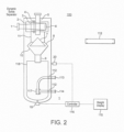
- FIGS. 2 , 3 and 4 show schematics of one of the Dynamic Solids Separators.
- FIG 2 the main components of the separator are shown and can be conveniently broken down into an upper, mid and lower section.
- the upper section with labels 1 through 6 represent the dynamic cyclone part of the separator.
- the mid section labelled 7 through 11 represents the particle diffusion and cleaned product outlet, 5.
- the lower section labelled 412 through 418 illustrates the solids collection and flushing components.
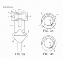
- FIG 3 in shown a more detailed illustration of the dynamic cyclone or upper section of a separator.
- the flow from an oil or gas well enters the separator through the inlet labelled 1.
- This inlet is generally circular and the start of a spiralled channel section that accelerates the flow velocity as the cross-sectional area of the channel is reducing along its length.
- a perspective view of the channel is shown in figure 4 .
- the channel inlet has a circular cross-section and the channel exit is rectangular.
- the area of the rectangular exit is -25% less than the area of the circular inlet giving rise to a flow velocity acceleration.
- it is also designed to impart a rotational or circular motion to the fluid flow as it exits the spiral channel.
- the inlet 1 is at one azimuth and the channel exit 16, shown on figure 3b , is on a different azimuth with the rotation from 1 to 16 being between 235 to 270 degrees. This can also be seen in figure 4 .
- the inlet is on a large diameter, 12 than the exit, which at the lower diameter labelled 13.
- This arrangement provides additional flow acceleration and rotation. It will be appreciated by those skilled in the art that the reduction in channel cross-section area and the change from a circular inlet to a rectangular outlet, can take many different forms. With the primary objectives to accelerate and rotate the flow entering the dynamic cyclone section.
- This component can be used to reduce the spiral channel exit cross-section area even further.
- a controlling mechanism 4 for this purpose.
- the component 4 can be spring loaded so that the exit area adjusts automatically in response to the pressure drop across the spiral channel. For example, as the flow velocity in the channel reduces due to, for example, lower production rates from the well, the pressure drop in the channel reduces and the spring-loaded restrictor closes a bit in order to reduce the channel exit area, increase the pressure drop at the channel exit and thus increase (or maintain) the velocity of the fluids exiting the channel.
- the regulator 4 can be an adjustment screw that can be accessed from outside the unit and which can be manually rotated to increase or decrease the exit cross-sectional area.
- 4 can be adjusted using electric or hydraulic actuation systems (not shown) that are linked to measurements that provide the pressure drop across the spiral channel or the flow exit velocity. As the pressure drop increases or decreases the flow restrictor 3 is automatically opened or closed to regulate the pressure drop and thus the exit flow velocity from the spiral channel.
- Those skilled in the art will be familiar with measurements and actuator systems commonly used for this type of regulator.
- Fluids exiting the spiral channel enter the top section of the particles separator at 16.
- the fluid is rotating rapidly and as a result particles in the fluid are thrown outwards by the centrifugal forces on the particles and become separated from the fluid flow.
- This is a function of particle size and large particles will experience larger forces than smaller one.
- the phenomenon is well understood and used in commercial Hydrocyclones, see http://www.energy.siemens.com/hq/en/industries-utilities/oil-gas/portfolio/water-solutions/hydrocyclones.htm.
- the dynamic velocity adjustment mechanism is designed to ensure correct pressure drop and flow velocity so even very fine particles are separated.
- a vortex is created in the unit with fluids rotating in the section 11 flowing downwards into the unit where it is disrupted by the particle diffuser, 7. As the fluids continue to rotating in the mid section 11 further solids particles separation takes place and the cleaned fluids exit the unit through the pipe 5.
- the separated particles drop out of the flow as their velocity is reduced while rotating close to inside wall, 13, of top section and the inside wall of the section 11. These particles drop and are dragged into the area between the particle diffuser, 7, and the lower section of the separator labelled 8.
- the diameter of the diffuser at its bottom is great that the internal diameter of 11. This ensures that the vortex is arrested and does not extend down into the area below the particle diffuser where if could pickup separated particles and drag them back up to the exit-pipe 5.
- the wall of 8 is expanding outwards so that the diameter of the chamber increases as the chamber progresses downwards as shown in figure 3a .
- the bottom of the chamber, 10 has an inverted conical shape so that the falling particles are collected and fall out of the unit through the pipe labelled 9.
- the cleaned fluid exit-pipe 5 has a diameters that is 1 ⁇ 4 that of section labelled 11.
- the tip of the particle diffuser, 7, is 1 diameter of the exit-pipe 5, below the bottom of the exit-pipe. While these dimension are found to provide favourable results other configurations with differing dimensions are possible.
- a spiral flow channel equipped with a flow restrictor that can regulate the velocity of the fluid exiting the spiral channel in order to optimise the solids particles separation in the unit.
- This flow restrictor can be controlled through manual intervention or by use of an automatic monitoring system.
- a method is here disclosed whereby the ratio of the mass of solids particles exiting with the cleaned fluid through exit-pipe 5, and the mass of solids particles exiting through the collection pipe, 9 is used to adjust the flow restrictor so that this ratio is minimised.
- the process steps are;
- the collection pipe 9 enters the collection bucket through a hole in the top of bucket 418, which is sealed to prevent particles exiting between collection pipe 9 and collection bucket 418 but allows some differential movement between the collection bucket 418 and the collection pipe 9.
- an elastomer grommet could be used.
- the solids collection bucket 418 will continue to fill with particles.
- the collection bucket, 418 is placed on a load-cell, 19, which measure the downward force on the bucket. Changes in this force is the result of two components; the changing weight of solids in the bucket and variations in the internal pressure in the unit.
- a separate pressure sensor, 20 is provided.
- the outputs from both the load-cell 19 and the pressure sensor 20 are fed into a controller 416.
- a real-time display connected to the controller showing the weight of solids particles collected in the bucket.
- the controller can also be connected to other computers or recording devices (not shown) to allow for real-time analysis and storage of the data and analysis.
- the controller can also be connected to pumps used in the flushing system that are triggered when the weight of collected solids particles reaches some threshold. When is occurs, the flow from the well is switch to flow through the second Dynamic Solids Separator and flushing of the collected solids particles in the collection bucket can take place.
- the flushing system comprises a water inlet 414, an annular fluidiser 417 and a water/solids outlet 413.
- the inlet 414, and outlet 413 are connected through annular gap between the wall of the Dynamic Solids Separator and the solids collection bucket using a section of pipe 412.
- These sections of pipe have ⁇ O' rings at each end and are slightly rounded at each end so that they allow relative movement between the sample collection bucket 418, and the solids separator body. This provides that the sample collection bucket 418 is coupled to a solids removal pipe 413 by a first flexible connector, such as an O-ring and to a liquid flushing pipe 414 by a second flexible connector, such as an O-ring.
- the bucket can move slightly as the weight of collected solids particles varies, as more solids are collected and as solids particles are flushed from the unit.
- Water injected into inlet 414 enters the annular fluidisation component.
- This component comprises downward jets that fluidises the solids particles and forces the resulting mixture of water and solids particles up through the central collection pipe 413 as the pressure in the bucket increases.
- a mixture of 50/50 water and solids particles is flushed from the solids collection bucket.
- the weight of solids as provided by the controller decreases. Once most of the collected particles have been flushed from the unit, the flushing pumps are switched off and fluid from the well can be directed into the dynamic cyclone once more.
- the solids particles flushed from the Dynamic Solids Separator represent the input flow to the Solids Buffer and Washing Plant as shown in figure 1 and by appropriate arrangement of the valves labelled 103. It should be noted that all of the valves shown through this invention can be operated manually or can be operated through an appropriate control system that will be appreciated by those skilled in the art and which is not shown.
- the plant has a solids particles separator unit and collection system, 201, which comprise the same components as the Dynamic Solids Separator as previous details in this invention.
- this unit functions at a low-pressure while the Dynamic Solids Separators operate at the higher well production pressure.
- the Sand Tank in the wash plant is significantly larger than the solids collection bucket in the solids separators. Generally it is ⁇ 10 times larger so that many cycles of flushing from the Dynamic Solids Separators can be buffered and treated at any one time.
- the operation of the component 201 is that same as the Dynamic Solids Separators already described, including its flushing fluidization component, 417, and solids buffer collector bucket weight measurement elements, that is, components; 19, 20, 415 and 416, that function in the same way.
- an oil separator, 202 that can be a cyclone or filter/absorption type or any other method that is known to those skilled in the art.
- FIG 5 it is shown as a cyclone, which is the preferred embodiment.
- a water circulation pump, 213, provided along with numerous valves that can be configured to achieve a desired flow circuit and these will be described using figure 7 to figure 9 .
- the circulation pump 213 is place downstream of the solids separation and cleaning components, which reduces the wear on this pump because it has clean fluids passing through it.
- the flow-paths are shown with arrows on the pipelines. It should be noted that the component label numbers in these figures are the same as those used in figures 2 and 5 .
- FIG. 6 a Production Sampling and Weight Bucket (PSWB) installed to allow solids samples to be taken from the production flow 303.
- Production is flowing from a number of wells, in Figure 6 , three wells are shown but this can be any number depending on the oil and gas field configuration.
- Each well has valves labelled 302 and 304 that can be operated manually or automatically controlled by a computerised process system, not shown, to either direct flow directly to the production flow stream 303 or through the Dynamic Solids Separators and Solids Buffer and Wash Plant.
- the Production Sample Weight Bucket is 'T' off the production flow manifold where the valve 301 controls flow into the Production Sample Weight Bucket.
- the PSWB can be arrange to collect samples continuously or periodically are required.
- valve 301 is closed and the bucket is flushed into the Solids Buffer and Wash Plant as described elsewhere.
- sample collecting the rate at which sand is collected in the PSWB is recorded by the controller 416 and is used to provide an indication that the sand content of the production flow is increasing. If excessive sand production is occurring it is possible selectively to shut each well one at a time (or in groups) in order to identify which well (or group of wells) is producing more sand.
- the production from this well can then be selectively routed through the Dynamic Solids Separator, that is, through the inlet labelled 1 in Figure 2 and then through the Solids Buffer and Wash plant as described elsewhere.
- the manifolds and piping required to make this happen are shown schematically in figure 6 but will depend on the platform configuration.
- the system shown in Figure 6 allows the automation of the solids separation unit and the solids buffer and wash plant providing a more efficient production platform.
- the system in figure 6 could equally be operated manually using readings recorded and shown in real-time on the display 415.
- Figure 7 illustrates the flushing circuit where solids separated in the solids separated collection bucket 418 are removed from the Dynamic Solids Separator to the Solids Buffer and Wash Plant 200.
- the particular solids separator that is being flushed is no longer receiving fluids from a well, as described previously, and fresh water is pumped from the inlet 203 using pump 213 into the fluidiser in the sample separator 100, through the inlet 414. Solids and water leaving the solids collection bucket through exit 413 are circulated into the Solids Buffer and Wash Plant 200 as shown in figure 7 .
- oil and water collected will exit from 204 in figures 5 , 7 , 8 and 9 .
- the cleaned solids will drop into the sand tank in the solids buffer and wash plant 201.
- the oil/water mix exits through 204 and enters the oil separator 202.
- the separated oil from this component exits into the 'dirty collection tank' (not shown) through 215. From there it will be disposed of by the usual environmentally acceptable manner or may enter the produced oil stream from the well.
- the separated water from 202 exits to be circulated using pump 213 back to the inlet 414 on the sample separator fluidisation flushing system and exits with solids through outlet 413. This circulation continues until the Dynamic Solids Separator solids collection bucket has been emptied. Once this has occurred, the Dynamic Solids Separator can be put back on-line to accept fluids from the well and the Solids Buffer and Wash Plant switches into a solids washing mode as shown in figure 8 .
- valves and pumps used through the system can be operated manually or can controlled using an automated system (not shown). During this process fresh water and/or washing chemicals enter the circuit when required through 203.
- the solids and water/chemicals continually circulate through the system as shown in figure 8 . On each cycle through the system, the solids are cleaned to a greater extent until such point that they carry minimal amounts of oil and are judge to be sufficiently clean to be disposed of by pumping them into the sea. This occurs using the circuit defined in figure 9 .
- sample can be collected at any time using the Production Sample Weight Bucket as shown in figure 1 , 300, and detailed in figure 6 . It would also be possible to use a multiphase flow meter to measure the oil/water ration of the flow leaving 204 and when the oil content is below a certain amount then further cleaning is not necessary.
- the MPFM can be utilised on any flow line within the system to determine the rates of any of the different phase (Oil, Gas, Water and Solids) within the flow and to further use this information to control the different steps in the process, e.g., adjust the inlet flow velocity to optimise the process.
- Figure 9 shows the flow circuit to flush the cleaned solids from the sand tank in the Solids Buffer and Washing Plant.
- fresh or seawater enters through 203 and is pumped through the fluidisation flushing system in 201 using pump 213.
- the water and cleaned solids particles mix exits the flushing system and is pumped into the sea through 206 or into a cleaned solids collection tank (not shown) as shown in figure 9 .
- Flushing continues until most of the cleaned solids particles have been removed from the sand tank as indicated by the solids weight system; 19, 20, 415 and 416, as shown in figure 5 .
- the flow circuit on the Solids Buffer and Washing Plant can be change to another mode, for example, to flush more separated particles from a Dynamic Solids Separator solids collection bucket into the solids.
- fluids flowing from an oil well or group of oil wells can have the solids removed.
- the solids separated can be cleaned of oil to a degree that allows for cost effective disposal of such particles. It also allow the oil remove for the said solids particles to be collected for potential feeding into the production stream thus extract as much usual production as possible.
Landscapes
- Mining & Mineral Resources (AREA)
- Life Sciences & Earth Sciences (AREA)
- Engineering & Computer Science (AREA)
- Geology (AREA)
- Physics & Mathematics (AREA)
- Fluid Mechanics (AREA)
- Environmental & Geological Engineering (AREA)
- General Life Sciences & Earth Sciences (AREA)
- Geochemistry & Mineralogy (AREA)
- Chemical & Material Sciences (AREA)
- Chemical Kinetics & Catalysis (AREA)
- Geometry (AREA)
- Cyclones (AREA)
- Separation Of Solids By Using Liquids Or Pneumatic Power (AREA)
- Separating Particles In Gases By Inertia (AREA)
Applications Claiming Priority (4)
| Application Number | Priority Date | Filing Date | Title |
|---|---|---|---|
| GB1420257.6A GB2529729B (en) | 2014-11-14 | 2014-11-14 | Solids separation, washing and sampling system |
| PCT/EP2015/076618 WO2016075317A2 (en) | 2014-11-14 | 2015-11-13 | Solids separation, washing and sampling system |
| EP15794581.7A EP3218115B1 (de) | 2014-11-14 | 2015-11-13 | Feststofftrennungs-, -wasch- und -probenahmesystem |
| EP21202936.7A EP3967406B1 (de) | 2014-11-14 | 2015-11-13 | Feststofftrennungs-, -wasch- und -probenahmesystem |
Related Parent Applications (3)
| Application Number | Title | Priority Date | Filing Date |
|---|---|---|---|
| EP15794581.7A Division EP3218115B1 (de) | 2014-11-14 | 2015-11-13 | Feststofftrennungs-, -wasch- und -probenahmesystem |
| EP21202936.7A Division EP3967406B1 (de) | 2014-11-14 | 2015-11-13 | Feststofftrennungs-, -wasch- und -probenahmesystem |
| EP21202936.7A Division-Into EP3967406B1 (de) | 2014-11-14 | 2015-11-13 | Feststofftrennungs-, -wasch- und -probenahmesystem |
Publications (2)
| Publication Number | Publication Date |
|---|---|
| EP4215280A2 true EP4215280A2 (de) | 2023-07-26 |
| EP4215280A3 EP4215280A3 (de) | 2024-01-10 |
Family
ID=52248355
Family Applications (3)
| Application Number | Title | Priority Date | Filing Date |
|---|---|---|---|
| EP23158311.3A Withdrawn EP4215280A3 (de) | 2014-11-14 | 2015-11-13 | Feststofftrennungs-, wasch- und probenahmesystem |
| EP15794581.7A Active EP3218115B1 (de) | 2014-11-14 | 2015-11-13 | Feststofftrennungs-, -wasch- und -probenahmesystem |
| EP21202936.7A Active EP3967406B1 (de) | 2014-11-14 | 2015-11-13 | Feststofftrennungs-, -wasch- und -probenahmesystem |
Family Applications After (2)
| Application Number | Title | Priority Date | Filing Date |
|---|---|---|---|
| EP15794581.7A Active EP3218115B1 (de) | 2014-11-14 | 2015-11-13 | Feststofftrennungs-, -wasch- und -probenahmesystem |
| EP21202936.7A Active EP3967406B1 (de) | 2014-11-14 | 2015-11-13 | Feststofftrennungs-, -wasch- und -probenahmesystem |
Country Status (5)
| Country | Link |
|---|---|
| EP (3) | EP4215280A3 (de) |
| DK (1) | DK3218115T3 (de) |
| EA (2) | EA038859B1 (de) |
| GB (2) | GB2529779B (de) |
| WO (1) | WO2016075317A2 (de) |
Families Citing this family (12)
| Publication number | Priority date | Publication date | Assignee | Title |
|---|---|---|---|---|
| GB2547044B (en) | 2016-02-08 | 2019-02-06 | Fourphase As | Oil, water, gas and solid particle separation in oil and/or gas production |
| GB2549977B (en) * | 2016-05-05 | 2019-07-24 | Fourphase As | Solids washing in oil and/or gas production |
| GB2573212B (en) * | 2016-08-19 | 2020-02-19 | Fourphase As | Solid particle separation in oil and/or gas production |
| CN106621582A (zh) * | 2016-12-19 | 2017-05-10 | 四川雷鸣环保装备有限公司 | 多极旋涡分离器 |
| MY199362A (en) | 2017-11-14 | 2023-10-24 | Dpi Group | Separated solids monitoring system |
| CN110813515A (zh) * | 2019-12-12 | 2020-02-21 | 西藏华泰龙矿业开发有限公司 | 一种高效旋流器 |
| AU2020426848B2 (en) | 2020-01-31 | 2026-03-05 | Fourphase As | Treatment of multiphase hydrocarbon-containing fluid in oil and/or gas production |
| GB2595491B (en) | 2020-05-28 | 2022-06-15 | Fourphase As | Apparatus for, and Method of, Controlling Sand Production from an Oil Well |
| CN115193124B (zh) * | 2021-04-08 | 2023-09-19 | 广东美的白色家电技术创新中心有限公司 | 分离器和家用设备 |
| CN114054223B (zh) * | 2021-11-15 | 2024-05-17 | 中国石油化工股份有限公司 | 一种排气管出口面积可调节的旋风分离器及其调节方法 |
| CN115370345B (zh) * | 2022-10-25 | 2023-01-10 | 四川凌耘建科技有限公司 | 页岩气自动排砂装置及方法 |
| US12436023B2 (en) | 2023-01-25 | 2025-10-07 | Mtc Americas, Llc | System and method for solids measurement on sand separator accumulators |
Family Cites Families (13)
| Publication number | Priority date | Publication date | Assignee | Title |
|---|---|---|---|---|
| DE2038045C3 (de) * | 1970-07-31 | 1981-12-10 | Siemens AG, 1000 Berlin und 8000 München | Zyklon |
| US3745752A (en) * | 1970-12-30 | 1973-07-17 | Envirotech Corp | Fluid inlet structure for cyclone collectors |
| DE2645137C2 (de) * | 1976-10-06 | 1978-05-03 | Kraftwerk Union Ag, 4330 Muelheim | Einrichtung zur Gewinnung von Ölprodukten aus ölsanden |
| JPS55139853A (en) * | 1979-04-20 | 1980-11-01 | Masayoshi Takee | Device for separating solid foreign matter from liquid |
| JPS581978B2 (ja) * | 1980-04-23 | 1983-01-13 | アサノエレコ株式会社 | 液体サイクロン形分離装置 |
| US4455220A (en) * | 1982-12-23 | 1984-06-19 | Shell Oil Company | Separation of fluid cracking catalyst particles from gaseous hydrocarbons |
| MY111234A (en) * | 1993-09-06 | 1999-09-30 | Merpro Tortek Ltd | Liquid / solid separation. |
| GB9419484D0 (en) * | 1994-09-28 | 1994-11-16 | Serck Baker Ltd | Treatment of particulate material |
| GB9802134D0 (en) * | 1998-02-02 | 1998-04-01 | Axsia Serck Baker Ltd | Improvements relating to oil-sand separation |
| GB2403440B (en) * | 2003-07-04 | 2007-09-05 | Dynamic Proc Solutions Plc | Separator |
| RU2341335C2 (ru) * | 2007-02-02 | 2008-12-20 | Федеральное государственное унитарное предприятие "Научно-исследовательский физико-химический институт имени Л.Я. Карпова" | Вихревой аппарат |
| EP2140932A1 (de) * | 2008-07-04 | 2010-01-06 | Ammonia Casale S.A. | Verfahren und Reaktor zur Oxidation von Kohlenwasserstoff |
| CN202570449U (zh) * | 2012-06-11 | 2012-12-05 | 威海市海王旋流器有限公司 | 一种螺旋进料体水力旋流器 |
-
2014
- 2014-11-14 GB GB1520712.9A patent/GB2529779B/en active Active
- 2014-11-14 GB GB1420257.6A patent/GB2529729B/en active Active
-
2015
- 2015-11-13 EP EP23158311.3A patent/EP4215280A3/de not_active Withdrawn
- 2015-11-13 DK DK15794581.7T patent/DK3218115T3/da active
- 2015-11-13 EA EA202090686A patent/EA038859B1/ru unknown
- 2015-11-13 EP EP15794581.7A patent/EP3218115B1/de active Active
- 2015-11-13 EP EP21202936.7A patent/EP3967406B1/de active Active
- 2015-11-13 EA EA201791033A patent/EA037383B1/ru unknown
- 2015-11-13 WO PCT/EP2015/076618 patent/WO2016075317A2/en not_active Ceased
Also Published As
| Publication number | Publication date |
|---|---|
| GB2529729A (en) | 2016-03-02 |
| DK3218115T3 (da) | 2022-01-24 |
| EA202090686A3 (ru) | 2020-10-30 |
| EA037383B1 (ru) | 2021-03-23 |
| EP3218115B1 (de) | 2021-12-08 |
| EP4215280A3 (de) | 2024-01-10 |
| GB2529779A (en) | 2016-03-02 |
| GB2529729B (en) | 2016-09-14 |
| EP3218115A2 (de) | 2017-09-20 |
| EA202090686A2 (ru) | 2020-06-30 |
| GB201520712D0 (en) | 2016-01-06 |
| EA038859B1 (ru) | 2021-10-28 |
| EP3967406B1 (de) | 2026-04-08 |
| WO2016075317A3 (en) | 2016-07-14 |
| WO2016075317A2 (en) | 2016-05-19 |
| EA201791033A1 (ru) | 2017-11-30 |
| GB201420257D0 (en) | 2014-12-31 |
| GB2529779B (en) | 2016-08-17 |
| EP3967406A1 (de) | 2022-03-16 |
Similar Documents
| Publication | Publication Date | Title |
|---|---|---|
| EP3967406B1 (de) | Feststofftrennungs-, -wasch- und -probenahmesystem | |
| AU2021206804B2 (en) | Solid particle separation in oil and/or gas production | |
| EA037695B1 (ru) | Разделение нефти, воды, газа и твердых частиц при добыче нефти и/или газа | |
| RU2552538C2 (ru) | Управление расположенным под водой циклоном | |
| US20130206007A1 (en) | Desanding apparatus and system | |
| US9327214B2 (en) | Desanding apparatus and a method of using same | |
| EP3292269B1 (de) | Feste teilchentrennung in der öl- und/oder gasproduktion | |
| US10478833B2 (en) | Fluid treatment system, a fluid processing apparatus and method of treating a mixture | |
| US20140008278A1 (en) | Oil-water separator | |
| US20140238817A1 (en) | Oil-water separator | |
| CA2848738C (en) | A desanding apparatus and a method of using same | |
| EP2883586B1 (de) | Flüssigkeitsbehandlungssystem und Verfahren zur Behandlung einer Mischung | |
| Rawlins | Design of a Cyclonic-Jetting and Slurry-Transport System for Separators | |
| Coffee | New Approach to Sand Removal | |
| EA042259B1 (ru) | Отделение твердых частиц при получении нефти и/или газа |
Legal Events
| Date | Code | Title | Description |
|---|---|---|---|
| PUAI | Public reference made under article 153(3) epc to a published international application that has entered the european phase |
Free format text: ORIGINAL CODE: 0009012 |
|
| STAA | Information on the status of an ep patent application or granted ep patent |
Free format text: STATUS: THE APPLICATION HAS BEEN PUBLISHED |
|
| AC | Divisional application: reference to earlier application |
Ref document number: 3218115 Country of ref document: EP Kind code of ref document: P Ref document number: 3967406 Country of ref document: EP Kind code of ref document: P |
|
| AK | Designated contracting states |
Kind code of ref document: A2 Designated state(s): AL AT BE BG CH CY CZ DE DK EE ES FI FR GB GR HR HU IE IS IT LI LT LU LV MC MK MT NL NO PL PT RO RS SE SI SK SM TR |
|
| P01 | Opt-out of the competence of the unified patent court (upc) registered |
Effective date: 20231024 |
|
| PUAL | Search report despatched |
Free format text: ORIGINAL CODE: 0009013 |
|
| AK | Designated contracting states |
Kind code of ref document: A3 Designated state(s): AL AT BE BG CH CY CZ DE DK EE ES FI FR GB GR HR HU IE IS IT LI LT LU LV MC MK MT NL NO PL PT RO RS SE SI SK SM TR |
|
| RIC1 | Information provided on ipc code assigned before grant |
Ipc: B04C 5/14 20060101ALI20231201BHEP Ipc: B04C 5/13 20060101ALI20231201BHEP Ipc: B04C 5/04 20060101AFI20231201BHEP |
|
| STAA | Information on the status of an ep patent application or granted ep patent |
Free format text: STATUS: THE APPLICATION IS DEEMED TO BE WITHDRAWN |
|
| 18D | Application deemed to be withdrawn |
Effective date: 20240711 |