EP4215432A1 - Cadre de bicyclette à absorption de choc de type caché - Google Patents
Cadre de bicyclette à absorption de choc de type caché Download PDFInfo
- Publication number
- EP4215432A1 EP4215432A1 EP22210491.1A EP22210491A EP4215432A1 EP 4215432 A1 EP4215432 A1 EP 4215432A1 EP 22210491 A EP22210491 A EP 22210491A EP 4215432 A1 EP4215432 A1 EP 4215432A1
- Authority
- EP
- European Patent Office
- Prior art keywords
- pair
- assembly
- hidden
- shock absorbing
- bicycle frame
- Prior art date
- Legal status (The legal status is an assumption and is not a legal conclusion. Google has not performed a legal analysis and makes no representation as to the accuracy of the status listed.)
- Granted
Links
Images





Classifications
-
- B—PERFORMING OPERATIONS; TRANSPORTING
- B62—LAND VEHICLES FOR TRAVELLING OTHERWISE THAN ON RAILS
- B62K—CYCLES; CYCLE FRAMES; CYCLE STEERING DEVICES; RIDER-OPERATED TERMINAL CONTROLS SPECIALLY ADAPTED FOR CYCLES; CYCLE AXLE SUSPENSIONS; CYCLE SIDECARS, FORECARS, OR THE LIKE
- B62K3/00—Bicycles
- B62K3/02—Frames
-
- B—PERFORMING OPERATIONS; TRANSPORTING
- B62—LAND VEHICLES FOR TRAVELLING OTHERWISE THAN ON RAILS
- B62K—CYCLES; CYCLE FRAMES; CYCLE STEERING DEVICES; RIDER-OPERATED TERMINAL CONTROLS SPECIALLY ADAPTED FOR CYCLES; CYCLE AXLE SUSPENSIONS; CYCLE SIDECARS, FORECARS, OR THE LIKE
- B62K25/00—Axle suspensions
- B62K25/04—Axle suspensions for mounting axles resiliently on cycle frame or fork
- B62K25/28—Axle suspensions for mounting axles resiliently on cycle frame or fork with pivoted chain-stay
- B62K25/286—Axle suspensions for mounting axles resiliently on cycle frame or fork with pivoted chain-stay the shock absorber being connected to the chain-stay via a linkage mechanism
-
- B—PERFORMING OPERATIONS; TRANSPORTING
- B62—LAND VEHICLES FOR TRAVELLING OTHERWISE THAN ON RAILS
- B62J—CYCLE SADDLES OR SEATS; AUXILIARY DEVICES OR ACCESSORIES SPECIALLY ADAPTED TO CYCLES AND NOT OTHERWISE PROVIDED FOR, e.g. ARTICLE CARRIERS OR CYCLE PROTECTORS
- B62J1/00—Saddles or other seats for cycles; Arrangement thereof; Component parts
- B62J1/08—Frames for saddles; Connections between saddle frames and seat pillars; Seat pillars
-
- B—PERFORMING OPERATIONS; TRANSPORTING
- B62—LAND VEHICLES FOR TRAVELLING OTHERWISE THAN ON RAILS
- B62K—CYCLES; CYCLE FRAMES; CYCLE STEERING DEVICES; RIDER-OPERATED TERMINAL CONTROLS SPECIALLY ADAPTED FOR CYCLES; CYCLE AXLE SUSPENSIONS; CYCLE SIDECARS, FORECARS, OR THE LIKE
- B62K19/00—Cycle frames
-
- B—PERFORMING OPERATIONS; TRANSPORTING
- B62—LAND VEHICLES FOR TRAVELLING OTHERWISE THAN ON RAILS
- B62K—CYCLES; CYCLE FRAMES; CYCLE STEERING DEVICES; RIDER-OPERATED TERMINAL CONTROLS SPECIALLY ADAPTED FOR CYCLES; CYCLE AXLE SUSPENSIONS; CYCLE SIDECARS, FORECARS, OR THE LIKE
- B62K19/00—Cycle frames
- B62K19/30—Frame parts shaped to receive other cycle parts or accessories
-
- B—PERFORMING OPERATIONS; TRANSPORTING
- B62—LAND VEHICLES FOR TRAVELLING OTHERWISE THAN ON RAILS
- B62K—CYCLES; CYCLE FRAMES; CYCLE STEERING DEVICES; RIDER-OPERATED TERMINAL CONTROLS SPECIALLY ADAPTED FOR CYCLES; CYCLE AXLE SUSPENSIONS; CYCLE SIDECARS, FORECARS, OR THE LIKE
- B62K25/00—Axle suspensions
- B62K25/04—Axle suspensions for mounting axles resiliently on cycle frame or fork
- B62K25/28—Axle suspensions for mounting axles resiliently on cycle frame or fork with pivoted chain-stay
- B62K25/30—Axle suspensions for mounting axles resiliently on cycle frame or fork with pivoted chain-stay pivoted on pedal crank shelf
-
- B—PERFORMING OPERATIONS; TRANSPORTING
- B62—LAND VEHICLES FOR TRAVELLING OTHERWISE THAN ON RAILS
- B62K—CYCLES; CYCLE FRAMES; CYCLE STEERING DEVICES; RIDER-OPERATED TERMINAL CONTROLS SPECIALLY ADAPTED FOR CYCLES; CYCLE AXLE SUSPENSIONS; CYCLE SIDECARS, FORECARS, OR THE LIKE
- B62K3/00—Bicycles
- B62K3/02—Frames
- B62K3/06—Frames of open type
-
- B—PERFORMING OPERATIONS; TRANSPORTING
- B62—LAND VEHICLES FOR TRAVELLING OTHERWISE THAN ON RAILS
- B62K—CYCLES; CYCLE FRAMES; CYCLE STEERING DEVICES; RIDER-OPERATED TERMINAL CONTROLS SPECIALLY ADAPTED FOR CYCLES; CYCLE AXLE SUSPENSIONS; CYCLE SIDECARS, FORECARS, OR THE LIKE
- B62K2201/00—Springs used in cycle frames or parts thereof
-
- B—PERFORMING OPERATIONS; TRANSPORTING
- B62—LAND VEHICLES FOR TRAVELLING OTHERWISE THAN ON RAILS
- B62M—RIDER PROPULSION OF WHEELED VEHICLES OR SLEDGES; POWERED PROPULSION OF SLEDGES OR SINGLE-TRACK CYCLES; TRANSMISSIONS SPECIALLY ADAPTED FOR SUCH VEHICLES
- B62M6/00—Rider propulsion of wheeled vehicles with additional source of power, e.g. combustion engine or electric motor
- B62M6/40—Rider propelled cycles with auxiliary electric motor
- B62M6/55—Rider propelled cycles with auxiliary electric motor power-driven at crank shafts parts
Definitions
- the present invention relates to a bicycle, and more particularly to a hidden-type shock absorbing bicycle frame which hides a damper inside a seat tube of the bicycle frame.
- a conventional shock absorbing bicycle frame has a front vehicle frame, a rear vehicle frame, and a damper. Generally, two ends of the damper are pivotally connected between the front vehicle frame and the rear vehicle frame, respectively. When a rear wheel of a bicycle is vibrated, the rear vehicle frame may absorb shocks by compressing the damper, so as to improve comfort of riding.
- Patent documents such as TW 1680903 , TW M544461 , and US 20120228850 A1 have disclosed detailed structures of the conventional shock absorbing bicycle frame. According to those patent documents, the damper of the conventional shock absorbing bicycle frame is exposed in front of a seat tube of the conventional shock absorbing bicycle frame.
- the exposed structure not only impairs completeness and simplicity of appearances of bicycles, but also makes the damper prone to situations such as being affected by external forces and foreign objects or being interfered and damaged by dust, mud, and sand, which reduces operation stability and lifespan of the damper. Also, during extension, contraction, and swing of the damper, a rider's clothing or accessories may be clipped, hindering convenience and safety of riding.
- the main objective of the present invention is to provide a hidden-type shock absorbing bicycle frame which hides a damper inside a seat tube of the bicycle frame for protecting the damper and improving completeness and simplicity of bicycle appearances, so as to overcome the aforementioned shortcomings of the exposed damper of the conventional shock absorbing bicycle frame.
- the hidden-type shock absorbing bicycle frame comprises a front vehicle frame, a transmission assembly, a rear vehicle frame, and a damper.
- the front vehicle frame comprises a seat tube substantially extending uprightly and having a lower end, a seatpost installation hole, and a pair of assembly plates.
- the seatpost installation hole is formed on an upper section of the seat tube.
- Each one of the pair of assembly plates has an upper pivot hole and a lower pivot hole.
- An assembly space is formed between the pair of the assembly plates and is substantially enclosed.
- the transmission assembly is pivotally connected to the upper pivot holes of the pair of assembly plates of the seat tube and comprises a pair of front arms and a pair of rear arms.
- the pair of front arms are located in the assembly space.
- Each one of the pair of rear arms is located at a respective one of two sides of the seat tube and extends backwardly.
- the rear vehicle frame comprises a pair of seat stays, a pair of chain stays, and a pair of dropouts.
- Each one of the pair of seat stays has a front end pivotally connected with a respective one of the pair of rear arms of the transmission assembly.
- Each one of the pair of chain stays has a front end pivotally connected with the lower end of the seat tube.
- Each one of the pair of dropouts is fixed to a rear end of a respective one of the pair of seat stays and a rear end of a respective one of the pair of chain stays.
- the damper is hidden inside the assembly space of the seat tube in a substantially upright configuration and has a top end and a bottom end. The top end of the damper is pivotally connected with the pair of front arms of the transmission assembly. The bottom end of the damper is pivotally connected to the lower pivot holes of the pair of assembly plates of the seat tube.
- a hidden-type shock absorbing bicycle frame in accordance with the present invention comprises a front vehicle frame 10, a rear vehicle frame 20, a seat tube 30 disposed on the front vehicle frame 10, a transmission assembly 40 pivotally connected between the seat tube 30 and the rear vehicle frame 20, and a damper 50 disposed inside the seat tube 30 and connected to the transmission assembly 40.
- the drawings depict a preferred embodiment of the present invention showing the hidden-type shock absorbing bicycle frame applied to an e-bike.
- the hidden-type shock absorbing bicycle frame in accordance with the present invention may also be applied to normal pedal-driven bicycles with rear dampers.
- the present invention is not restricted to specific power types of bicycles.
- the front vehicle frame 10 includes a head tube 11 for mounting a fork, a down tube 12 which has a front end connected with the head tube 11 and extends backwardly and downwardly, a motor holder 13 connected to a rear end of the down tube 12, and the seat tube 30 substantially extending uprightly and having a lower end fixed to a top portion of the motor holder 13.
- the seat tube 30 is configured for installation of a saddle, and the motor holder 13 is configured to hold a driving motor 14.
- the rear vehicle frame 20 comprises a pair of seat stays 21, a pair of chain stays 22, and a pair of dropouts 23 which are connected between the pair of seat stays 21 and the pair of chain stays 22.
- Each one of the pair of seat stays 21 has a front end serving as a connecting end 211 behind the one of two sides of the seat tube 30.
- the connecting ends 211 of the pair of the seat stays 21 have a pair of pivot holes mutually aligned for being pivotally connected to the transmission assembly 40.
- Each one of the pair of chain stays 22 has a front end serving as a connecting end 221 extending above the motor holder 13 and located on one of the two sides of the lower end of the seat tube 30.
- the connecting ends 221 of the pair of the chain stays 22 have a pair of pivot holes mutually aligned, and the connecting ends 221 of the pair of chain stays 22 are pivotally connected with the lower end of the seat tube 30 via a first pivot assembly 222 passing through the pair of pivot holes of the connecting ends 221 of the pair of chain stays 22.
- the rear vehicle frame 20 is configured to swing up and down with respect to the front vehicle frame 10.
- the seat tube 30 comprises an assembly base 31 substantially extending uprightly and connected with the motor holder 13, a post tube 32 substantially extending uprightly and fixed with the assembly base 31, a cover 33 detachably mounted on the post tube 32, and a locking socket 34 connected to a top end of the post tube 32.
- the assembly base 31 is a frame structure and has a pair of assembly plates 311 that are disposed at a spaced interval. An assembly space 312 is formed between the pair of the assembly plates 311.
- the assembly base 31 has a back plate one-piece connected with back sides of the pair of assembly plates 311, so the assembly base 31 forms a U-shaped frame structure having an opening at a front side of the assembly base 31.
- front edges and a top edge of the assembly base 31 constitute a connecting edge 313 for connection with the post tube 32.
- the assembly base 31 may have the opening at a rear side of the assembly base 31, or the assembly base 31 only has the pair of assembly plates 311 without the back plate.
- each one of the pair of assembly plates 311 has an upper pivot hole 314, a lower pivot hole 315, and a rear pivot hole 316 behind the lower pivot hole 315.
- the rear pivot holes 316 of the pair of the assembly plates 311 are used for pivotally connecting the connecting ends 221 of the pair of chain stays 22, respectively.
- a lower section of the post tube 32 is recessed and forms a connecting edge 321 that matches with the connecting edge 313 of the assembly base 31, so the post tube 32 and the assembly base 31 are configured to match each other and fixed together to form the substantially uprightly extending seat tube 31.
- the post tube 32 has an assembly hole 322 disposed through a front side of the lower section of the post tube 32. The assembly hole 322 communicates with the assembly space 312, facilitating installation and detachment of the transmission assembly 40 and the damper 50.
- the cover 33 is configured to shield the assembly hole 322 by being detachably mounted thereto.
- An axial position of an upper section of the post tube 323 forms a seatpost installation hole 323 for installing a seatpost of a bicycle.
- the post tube 32 has multiple ribs 324 disposed at spaced intervals and connected with the seatpost installation hole 323 to support the seatpost installation hole 323, so as to reduce material and weight of the post tube 32.
- the post tube 32 and the assembly base 31 are connected by welding the connecting edges 321, 313 of the assembly base 31 and the post tube 32.
- the assembly base 31 and the post tube 32 may be a one-piece structure made by casting, extruding, molding, etc., the present invention is not limited to the above.
- the locking socket 34 is connected to a top end of the post tube 32 and has a tubular hole 341 aligned with the seatpost installation hole 323 and a clamping part 342 configured to narrow the tubular hole 341.
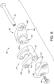
- the transmission assembly 40 comprises an arm base 41, a pair of side arm components 42 mounted on two sides of the arm base 41, a pair of bearings 43 mounted between the pair of the side arm components 42 and the arm base 41, a pair of flexible spacers 44, and an axle 45 assembling the aforementioned components.
- the arm base 41 has an axle portion 411 disposed transversely and a pair of front arms 412 extending from two ends of the axle portion 411, respectively.
- the pair of the front arms 412 has a pair of pivot holes 4121 on front ends of the pair of front arms 412.
- the axle portion 411 has an axle hole 413 disposed transversely therethrough for the axle 45 to pass through.
- the arm base 41 has a pair of engaging grooves 414 recessed from the two ends of the axle portion 41 and being non-circular.
- the pair of engaging grooves 414 may be polygonal such as quadrilateral and hexagonal, plumblossom-shaped, oval, semicircular, etc., the present invention is not limited to the above. With reference to Fig. 6 , the pair of engaging grooves 414 are semicircular.
- Each one of the pair of side arm components 42 has an engaging head 421 engaged with a respective one of the pair of engaging grooves 414 and a rear arm 422 extending backwardly.
- the engaging head 421 has an engaging block 4211 and an axle hole 423. A shape of the engaging block 4211 matches the corresponding engaging groove 414.
- the axle hole 423 is disposed through the side arm component 42 for the axle 45 to pass through.
- the rear arm 42 has a pivot hole 4221 disposed on a rear end thereof.
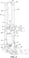
- the arm base 41 is firstly put into the assembly space 312 of the assembly base 31 via the assembly hole 322, and the pair of bearings 43 and the pair of flexible spacers 44 are respectively sheathed on the engaging heads 421 of the pair of side arm components 42. Then the engaging heads 421 of the pair of side arm components 42 are inserted into and engaged with the pair of engaging grooves 414 of the arm base 41 through the upper pivot holes 314 of the assembly base 31. Eventually, the axle 45 passes through the axle holes 423, 413 of the pair of side arm components 42 and the arm base 41, and is screwed with a bolt 46. Thereby, with reference to Figs. 4 and 7 , the transmission assembly 40 is swingably mounted with the assembly base 31 of the seat tube 30.
- Each one of the pair of bearings 43 is disposed between the engaging head 421 of the corresponding side arm component 42 and the corresponding upper pivot hole 314.
- Each one of the pair of flexible spacers 44 is clamped between the corresponding bearing 43 and the axle portion 411 of the arm base 41.
- the damper 50 is disposed inside the assembly space 312 of the seat tube 30 in a substantially upright configuration.
- Each one of a top end and a bottom end of the damper 50 is formed as a pivot head 51.
- the pivot head 51 at the top end of the damper 50 is disposed between the pivot holes 4121 of the pair of front arms 412 of the transmission assembly 40 with a second pivot assembly 511 passing through for pivotally connecting the pivot head 51 at the top end of the damper 50 with the pair of front arms 412 of the transmission assembly 40.
- the pivot head 51 at the bottom end of the damper 50 is disposed between the lower pivot holes 315 of the assembly base 31.
- a third pivot assembly 521 passing through the pivot head 51 and the lower pivot holes 315 the pivot head 51 at the bottom end of the damper 50 is pivotally connected to the assembly base 31, so when the transmission assembly 40 is affected by the rear vehicle frame 20 and thereby swings, the transmission assembly 40 makes the damper 50 compressed or extended, so as to provide efficacy of supporting, shock absorbing, and restoring during a damping process.
- the present invention utilizes the components such as the seat tube 30 which has the assembly base 312, the rear vehicle frame 20, the transmission assembly 40, the damper 50 and so on to constitute the hidden-type shock absorbing bicycle frame as shown in Figs. 1 to 3 .
- Fixing methods for the components mentioned above can be welding, mechanical mounting, or one-piece forming, the present invention is not limited thereto.
- the seat tube 30 with the assembly space 312 inside can hide the damper 50 inside the seat tube 30 with the transmission assembly 40 being an assembled structure.
- the damper 50 can be prevented from being hit or rubbed by external forces and foreign objects and being interfered and damaged by dust, mud, and sand because the damper 50 is hidden inside. Therefore, operational stability and lifespan of the shock absorbing bicycle frame is improved and prolonged.
- the transmission assembly 40 being an assembled structure provides convenience in installing the transmission assembly 40 to the assembly base 31 and enables the damper 50 inside the seat tube 30 to be connected and cooperate with the rear vehicle frame 20 behind the seat tube 30.
Landscapes
- Engineering & Computer Science (AREA)
- Mechanical Engineering (AREA)
- Axle Suspensions And Sidecars For Cycles (AREA)
Applications Claiming Priority (1)
| Application Number | Priority Date | Filing Date | Title |
|---|---|---|---|
| TW111200796U TWM626633U (zh) | 2022-01-20 | 2022-01-20 | 隱藏式避震車架 |
Publications (2)
| Publication Number | Publication Date |
|---|---|
| EP4215432A1 true EP4215432A1 (fr) | 2023-07-26 |
| EP4215432B1 EP4215432B1 (fr) | 2025-08-27 |
Family
ID=82559351
Family Applications (1)
| Application Number | Title | Priority Date | Filing Date |
|---|---|---|---|
| EP22210491.1A Active EP4215432B1 (fr) | 2022-01-20 | 2022-11-30 | Cadre de bicyclette à absorption de choc de type caché |
Country Status (3)
| Country | Link |
|---|---|
| US (1) | US12497120B2 (fr) |
| EP (1) | EP4215432B1 (fr) |
| TW (1) | TWM626633U (fr) |
Cited By (1)
| Publication number | Priority date | Publication date | Assignee | Title |
|---|---|---|---|---|
| DE102025112316B3 (de) * | 2025-03-28 | 2026-02-12 | Matthias Blümel | Rahmenstruktur für ein Fahrrad |
Families Citing this family (11)
| Publication number | Priority date | Publication date | Assignee | Title |
|---|---|---|---|---|
| US20230400080A1 (en) * | 2022-06-10 | 2023-12-14 | Fox Factory, Inc. | Integrated bearing hardware for shock assembly |
| ES2935649B2 (es) * | 2022-12-27 | 2023-07-18 | Berria Bike S L | Cuadro de bicicleta con amortiguacion integrada de facil acceso |
| IT202300006015A1 (it) * | 2023-03-29 | 2024-09-29 | Fantic Motor S P A | Sospensione posteriore per biciclette |
| USD1069652S1 (en) * | 2023-07-28 | 2025-04-08 | Freeman It Limited | Electric bicycle |
| USD1072678S1 (en) * | 2023-09-22 | 2025-04-29 | Shenzhen Tesgo Electric Technology Co., Ltd. | Electric bike |
| USD1075581S1 (en) * | 2023-09-25 | 2025-05-20 | Qiang Peng | Electric bicycle |
| USD1077685S1 (en) * | 2023-10-12 | 2025-06-03 | G-Force Inc | Electric bicycle |
| CA229974S (en) * | 2023-12-29 | 2025-02-18 | Ninebot Shenzhen Tech Co Ltd | Bicycle |
| USD1124965S1 (en) * | 2024-07-08 | 2026-05-05 | Freeman It Limited | Electric bicycle |
| USD1114683S1 (en) * | 2024-12-27 | 2026-02-24 | Shenzhen Yingfeng Intelligent Technology Co., Ltd. | Electric bicycle |
| USD1126057S1 (en) * | 2025-01-15 | 2026-05-12 | Dongguan Lingfeng Tech Co., Ltd | Electric bicycle |
Citations (4)
| Publication number | Priority date | Publication date | Assignee | Title |
|---|---|---|---|---|
| US20120228850A1 (en) | 2011-03-10 | 2012-09-13 | Kinesis Industry Co., Ltd. | Rear suspension system for bicycles |
| TWM544461U (zh) | 2017-03-20 | 2017-07-01 | A-Pro Tech Co Ltd | 內樞接五通裝置及具有內樞接五通裝置的自行車車架 |
| US10071786B2 (en) * | 2013-10-11 | 2018-09-11 | Flow Ag | Two-wheeled vehicle with rear-wheel suspension |
| TWI680903B (zh) | 2018-02-09 | 2020-01-01 | 巨大機械工業股份有限公司 | 自行車用車架 |
Family Cites Families (4)
| Publication number | Priority date | Publication date | Assignee | Title |
|---|---|---|---|---|
| IT1253773B (it) * | 1991-10-23 | 1995-08-23 | Dei Claudio De | Dispositivo di ammortizzazione posteriore per bicicletta |
| US20060237274A1 (en) * | 2005-03-30 | 2006-10-26 | Hsia Chun M | Shock absorbing device for cycle |
| CN106926957A (zh) * | 2017-03-17 | 2017-07-07 | 泰山体育产业集团有限公司 | 复合材料自行车隐藏式避震装置 |
| US10618595B2 (en) * | 2017-03-23 | 2020-04-14 | Darrell W Voss | Vehicle |
-
2022
- 2022-01-20 TW TW111200796U patent/TWM626633U/zh unknown
- 2022-11-29 US US18/070,720 patent/US12497120B2/en active Active
- 2022-11-30 EP EP22210491.1A patent/EP4215432B1/fr active Active
Patent Citations (4)
| Publication number | Priority date | Publication date | Assignee | Title |
|---|---|---|---|---|
| US20120228850A1 (en) | 2011-03-10 | 2012-09-13 | Kinesis Industry Co., Ltd. | Rear suspension system for bicycles |
| US10071786B2 (en) * | 2013-10-11 | 2018-09-11 | Flow Ag | Two-wheeled vehicle with rear-wheel suspension |
| TWM544461U (zh) | 2017-03-20 | 2017-07-01 | A-Pro Tech Co Ltd | 內樞接五通裝置及具有內樞接五通裝置的自行車車架 |
| TWI680903B (zh) | 2018-02-09 | 2020-01-01 | 巨大機械工業股份有限公司 | 自行車用車架 |
Cited By (1)
| Publication number | Priority date | Publication date | Assignee | Title |
|---|---|---|---|---|
| DE102025112316B3 (de) * | 2025-03-28 | 2026-02-12 | Matthias Blümel | Rahmenstruktur für ein Fahrrad |
Also Published As
| Publication number | Publication date |
|---|---|
| EP4215432B1 (fr) | 2025-08-27 |
| US12497120B2 (en) | 2025-12-16 |
| US20230227119A1 (en) | 2023-07-20 |
| TWM626633U (zh) | 2022-05-01 |
Similar Documents
| Publication | Publication Date | Title |
|---|---|---|
| EP4215432B1 (fr) | Cadre de bicyclette à absorption de choc de type caché | |
| US20090072512A1 (en) | Bicycle rear suspension system | |
| US8403350B2 (en) | Seatstay suspension mount | |
| US20110042917A1 (en) | Bicycle frame dropouts and methods | |
| US20080238031A1 (en) | Bicycle frame | |
| DE69817347D1 (de) | Hinteraufhängung für fahrräder | |
| CA2197504C (fr) | Fourche arriere et un bras oscillant | |
| JP4425821B2 (ja) | 収納ボックス構造 | |
| EP2007617B1 (fr) | Cadres de bicyclette et bicyclettes a garde-boue permanent de roue arriere | |
| US20210163092A1 (en) | Bicycle with compliant seat post interface | |
| CN212861712U (zh) | 连杆式避震座管 | |
| US5570753A (en) | Motorcycle engine and transmission torque-resisting arm | |
| US20030067137A1 (en) | Structure for fast removal of absorber for foldable bike | |
| JP3044981U (ja) | 自動二輪車のフォークトリプル | |
| US6581713B2 (en) | Engine suspension device of a beach buggy | |
| US20080277898A1 (en) | Reinforced motorcycle frame | |
| CN210175050U (zh) | 跨乘型车辆 | |
| JP6944483B2 (ja) | 鞍乗り型車両のクッションユニット支持構造 | |
| TWI894846B (zh) | 組合式車架 | |
| TWM679076U (zh) | 可吸震之自行車豎管總成 | |
| JP2003104267A (ja) | スクータ型自動二輪車の車体フレーム | |
| JP7415768B2 (ja) | ハンドル | |
| JP3147119B2 (ja) | スクータ型車両 | |
| JP3147118B2 (ja) | スクータ型車両 | |
| EP1980481B1 (fr) | Cadre de bicyclette |
Legal Events
| Date | Code | Title | Description |
|---|---|---|---|
| PUAI | Public reference made under article 153(3) epc to a published international application that has entered the european phase |
Free format text: ORIGINAL CODE: 0009012 |
|
| STAA | Information on the status of an ep patent application or granted ep patent |
Free format text: STATUS: THE APPLICATION HAS BEEN PUBLISHED |
|
| AK | Designated contracting states |
Kind code of ref document: A1 Designated state(s): AL AT BE BG CH CY CZ DE DK EE ES FI FR GB GR HR HU IE IS IT LI LT LU LV MC ME MK MT NL NO PL PT RO RS SE SI SK SM TR |
|
| STAA | Information on the status of an ep patent application or granted ep patent |
Free format text: STATUS: REQUEST FOR EXAMINATION WAS MADE |
|
| 17P | Request for examination filed |
Effective date: 20230926 |
|
| RBV | Designated contracting states (corrected) |
Designated state(s): AL AT BE BG CH CY CZ DE DK EE ES FI FR GB GR HR HU IE IS IT LI LT LU LV MC ME MK MT NL NO PL PT RO RS SE SI SK SM TR |
|
| RIC1 | Information provided on ipc code assigned before grant |
Ipc: B62M 6/55 20100101ALN20250423BHEP Ipc: B62K 25/30 20060101ALI20250423BHEP Ipc: B62K 3/06 20060101ALI20250423BHEP Ipc: B62K 19/30 20060101ALI20250423BHEP Ipc: B62K 25/28 20060101AFI20250423BHEP |
|
| GRAP | Despatch of communication of intention to grant a patent |
Free format text: ORIGINAL CODE: EPIDOSNIGR1 |
|
| STAA | Information on the status of an ep patent application or granted ep patent |
Free format text: STATUS: GRANT OF PATENT IS INTENDED |
|
| RIC1 | Information provided on ipc code assigned before grant |
Ipc: B62M 6/55 20100101ALN20250508BHEP Ipc: B62K 25/30 20060101ALI20250508BHEP Ipc: B62K 3/06 20060101ALI20250508BHEP Ipc: B62K 19/30 20060101ALI20250508BHEP Ipc: B62K 25/28 20060101AFI20250508BHEP |
|
| INTG | Intention to grant announced |
Effective date: 20250530 |
|
| GRAS | Grant fee paid |
Free format text: ORIGINAL CODE: EPIDOSNIGR3 |
|
| GRAA | (expected) grant |
Free format text: ORIGINAL CODE: 0009210 |
|
| STAA | Information on the status of an ep patent application or granted ep patent |
Free format text: STATUS: THE PATENT HAS BEEN GRANTED |
|
| AK | Designated contracting states |
Kind code of ref document: B1 Designated state(s): AL AT BE BG CH CY CZ DE DK EE ES FI FR GB GR HR HU IE IS IT LI LT LU LV MC ME MK MT NL NO PL PT RO RS SE SI SK SM TR |
|
| REG | Reference to a national code |
Ref country code: CH Ref legal event code: EP |
|
| REG | Reference to a national code |
Ref country code: DE Ref legal event code: R096 Ref document number: 602022020163 Country of ref document: DE |
|
| REG | Reference to a national code |
Ref country code: IE Ref legal event code: FG4D |
|
| REG | Reference to a national code |
Ref country code: NL Ref legal event code: MP Effective date: 20250827 |
|
| PG25 | Lapsed in a contracting state [announced via postgrant information from national office to epo] |
Ref country code: IS Free format text: LAPSE BECAUSE OF FAILURE TO SUBMIT A TRANSLATION OF THE DESCRIPTION OR TO PAY THE FEE WITHIN THE PRESCRIBED TIME-LIMIT Effective date: 20251227 |
|
| PGFP | Annual fee paid to national office [announced via postgrant information from national office to epo] |
Ref country code: DE Payment date: 20250917 Year of fee payment: 4 |
|
| PG25 | Lapsed in a contracting state [announced via postgrant information from national office to epo] |
Ref country code: NO Free format text: LAPSE BECAUSE OF FAILURE TO SUBMIT A TRANSLATION OF THE DESCRIPTION OR TO PAY THE FEE WITHIN THE PRESCRIBED TIME-LIMIT Effective date: 20251127 |
|
| REG | Reference to a national code |
Ref country code: LT Ref legal event code: MG9D |
|
| PG25 | Lapsed in a contracting state [announced via postgrant information from national office to epo] |
Ref country code: PT Free format text: LAPSE BECAUSE OF FAILURE TO SUBMIT A TRANSLATION OF THE DESCRIPTION OR TO PAY THE FEE WITHIN THE PRESCRIBED TIME-LIMIT Effective date: 20251229 |
|
| PG25 | Lapsed in a contracting state [announced via postgrant information from national office to epo] |
Ref country code: FI Free format text: LAPSE BECAUSE OF FAILURE TO SUBMIT A TRANSLATION OF THE DESCRIPTION OR TO PAY THE FEE WITHIN THE PRESCRIBED TIME-LIMIT Effective date: 20250827 |
|
| PG25 | Lapsed in a contracting state [announced via postgrant information from national office to epo] |
Ref country code: HR Free format text: LAPSE BECAUSE OF FAILURE TO SUBMIT A TRANSLATION OF THE DESCRIPTION OR TO PAY THE FEE WITHIN THE PRESCRIBED TIME-LIMIT Effective date: 20250827 Ref country code: NL Free format text: LAPSE BECAUSE OF FAILURE TO SUBMIT A TRANSLATION OF THE DESCRIPTION OR TO PAY THE FEE WITHIN THE PRESCRIBED TIME-LIMIT Effective date: 20250827 |
|
| PG25 | Lapsed in a contracting state [announced via postgrant information from national office to epo] |
Ref country code: GR Free format text: LAPSE BECAUSE OF FAILURE TO SUBMIT A TRANSLATION OF THE DESCRIPTION OR TO PAY THE FEE WITHIN THE PRESCRIBED TIME-LIMIT Effective date: 20251128 |
|
| PG25 | Lapsed in a contracting state [announced via postgrant information from national office to epo] |
Ref country code: SE Free format text: LAPSE BECAUSE OF FAILURE TO SUBMIT A TRANSLATION OF THE DESCRIPTION OR TO PAY THE FEE WITHIN THE PRESCRIBED TIME-LIMIT Effective date: 20250827 |
|
| PG25 | Lapsed in a contracting state [announced via postgrant information from national office to epo] |
Ref country code: LV Free format text: LAPSE BECAUSE OF FAILURE TO SUBMIT A TRANSLATION OF THE DESCRIPTION OR TO PAY THE FEE WITHIN THE PRESCRIBED TIME-LIMIT Effective date: 20250827 |
|
| PG25 | Lapsed in a contracting state [announced via postgrant information from national office to epo] |
Ref country code: PL Free format text: LAPSE BECAUSE OF FAILURE TO SUBMIT A TRANSLATION OF THE DESCRIPTION OR TO PAY THE FEE WITHIN THE PRESCRIBED TIME-LIMIT Effective date: 20250827 Ref country code: BG Free format text: LAPSE BECAUSE OF FAILURE TO SUBMIT A TRANSLATION OF THE DESCRIPTION OR TO PAY THE FEE WITHIN THE PRESCRIBED TIME-LIMIT Effective date: 20250827 |
|
| PG25 | Lapsed in a contracting state [announced via postgrant information from national office to epo] |
Ref country code: RS Free format text: LAPSE BECAUSE OF FAILURE TO SUBMIT A TRANSLATION OF THE DESCRIPTION OR TO PAY THE FEE WITHIN THE PRESCRIBED TIME-LIMIT Effective date: 20251127 |
|
| PG25 | Lapsed in a contracting state [announced via postgrant information from national office to epo] |
Ref country code: ES Free format text: LAPSE BECAUSE OF FAILURE TO SUBMIT A TRANSLATION OF THE DESCRIPTION OR TO PAY THE FEE WITHIN THE PRESCRIBED TIME-LIMIT Effective date: 20250827 |
|
| REG | Reference to a national code |
Ref country code: AT Ref legal event code: MK05 Ref document number: 1829718 Country of ref document: AT Kind code of ref document: T Effective date: 20250827 |
|
| PG25 | Lapsed in a contracting state [announced via postgrant information from national office to epo] |
Ref country code: RO Free format text: LAPSE BECAUSE OF FAILURE TO SUBMIT A TRANSLATION OF THE DESCRIPTION OR TO PAY THE FEE WITHIN THE PRESCRIBED TIME-LIMIT Effective date: 20250827 |
|
| PG25 | Lapsed in a contracting state [announced via postgrant information from national office to epo] |
Ref country code: SM Free format text: LAPSE BECAUSE OF FAILURE TO SUBMIT A TRANSLATION OF THE DESCRIPTION OR TO PAY THE FEE WITHIN THE PRESCRIBED TIME-LIMIT Effective date: 20250827 |
|
| PG25 | Lapsed in a contracting state [announced via postgrant information from national office to epo] |
Ref country code: DK Free format text: LAPSE BECAUSE OF FAILURE TO SUBMIT A TRANSLATION OF THE DESCRIPTION OR TO PAY THE FEE WITHIN THE PRESCRIBED TIME-LIMIT Effective date: 20250827 |
|
| PG25 | Lapsed in a contracting state [announced via postgrant information from national office to epo] |
Ref country code: AT Free format text: LAPSE BECAUSE OF FAILURE TO SUBMIT A TRANSLATION OF THE DESCRIPTION OR TO PAY THE FEE WITHIN THE PRESCRIBED TIME-LIMIT Effective date: 20250827 |
|
| PG25 | Lapsed in a contracting state [announced via postgrant information from national office to epo] |
Ref country code: IT Free format text: LAPSE BECAUSE OF FAILURE TO SUBMIT A TRANSLATION OF THE DESCRIPTION OR TO PAY THE FEE WITHIN THE PRESCRIBED TIME-LIMIT Effective date: 20250827 |
|
| PG25 | Lapsed in a contracting state [announced via postgrant information from national office to epo] |
Ref country code: CZ Free format text: LAPSE BECAUSE OF FAILURE TO SUBMIT A TRANSLATION OF THE DESCRIPTION OR TO PAY THE FEE WITHIN THE PRESCRIBED TIME-LIMIT Effective date: 20250827 |
|
| PG25 | Lapsed in a contracting state [announced via postgrant information from national office to epo] |
Ref country code: SK Free format text: LAPSE BECAUSE OF FAILURE TO SUBMIT A TRANSLATION OF THE DESCRIPTION OR TO PAY THE FEE WITHIN THE PRESCRIBED TIME-LIMIT Effective date: 20250827 Ref country code: EE Free format text: LAPSE BECAUSE OF FAILURE TO SUBMIT A TRANSLATION OF THE DESCRIPTION OR TO PAY THE FEE WITHIN THE PRESCRIBED TIME-LIMIT Effective date: 20250827 |