EP4215459A1 - Dispositif pour vider les poubelles - Google Patents
Dispositif pour vider les poubelles Download PDFInfo
- Publication number
- EP4215459A1 EP4215459A1 EP23151242.7A EP23151242A EP4215459A1 EP 4215459 A1 EP4215459 A1 EP 4215459A1 EP 23151242 A EP23151242 A EP 23151242A EP 4215459 A1 EP4215459 A1 EP 4215459A1
- Authority
- EP
- European Patent Office
- Prior art keywords
- lever
- rotation
- axis
- truck
- lifting
- Prior art date
- Legal status (The legal status is an assumption and is not a legal conclusion. Google has not performed a legal analysis and makes no representation as to the accuracy of the status listed.)
- Pending
Links
Images


Classifications
-
- B—PERFORMING OPERATIONS; TRANSPORTING
- B65—CONVEYING; PACKING; STORING; HANDLING THIN OR FILAMENTARY MATERIAL
- B65F—GATHERING OR REMOVAL OF DOMESTIC OR LIKE REFUSE
- B65F3/00—Vehicles particularly adapted for collecting refuse
- B65F3/02—Vehicles particularly adapted for collecting refuse with means for discharging refuse receptacles thereinto
- B65F3/08—Platform elevators or hoists with guides or runways for raising or tipping receptacles
-
- B—PERFORMING OPERATIONS; TRANSPORTING
- B65—CONVEYING; PACKING; STORING; HANDLING THIN OR FILAMENTARY MATERIAL
- B65F—GATHERING OR REMOVAL OF DOMESTIC OR LIKE REFUSE
- B65F3/00—Vehicles particularly adapted for collecting refuse
- B65F3/24—Vehicles particularly adapted for collecting refuse with devices for unloading the tank of a refuse vehicle
- B65F3/26—Vehicles particularly adapted for collecting refuse with devices for unloading the tank of a refuse vehicle by tipping the tank
Definitions
- the invention relates to a device for emptying refuse containers, which can be arranged at the dumping opening of a refuse collection container, with a lift truck, having a receiving device for receiving a refuse container, a shaft which is mounted rotatably about an axis of rotation, with a traction means and a drive for the traction means arranged above the dumping opening, in order to drive the lift truck to perform a lifting movement and/or a rotary movement.
- Garbage containers are emptied into garbage collection containers with the help of lifting and tipping devices, which are designed, for example, as superstructures of garbage collection vehicles.
- the waste container is lifted off the ground in a lifting movement and tilted in a rotating movement.
- a shaft is driven, which sets a lifting truck, which picks up and holds the garbage container, into a rotational movement.
- WO 2004 083 077 A1 discloses a device for emptying refuse containers with a drive which is arranged above the pouring-in opening of a refuse collection container and drives a traction means which causes a lift truck for a refuse container to perform a lifting movement.
- the upward movement of the lift truck is blocked at a specified height.
- the traction mechanism continues to exert a tensile force on the truck, the truck is tilted and rotated.
- the traction mechanism acts on the lift truck in the vicinity of the axis of rotation, around which the rotary movement takes place. This arrangement has the disadvantage that a great deal of force has to be applied for the torque required for the rotational movement.
- the invention relates to a device for emptying refuse containers, which can be arranged at the pouring opening of a refuse collection container, with a lift truck, having a receiving device for receiving a garbage container, a shaft, which is mounted rotatably about an axis of rotation, with a traction mechanism and a drive for the traction mechanism, which is arranged above the pouring-in opening, in order to drive the lifting carriage to perform a lifting movement and/or a rotary movement, a lever being arranged on the lifting carriage, on which the traction mechanism acts.
- the device is preferably arranged on a refuse collection container which is provided as a structure on a refuse collection vehicle.
- a refuse container is placed on the truck.
- recording devices are provided, for example a comb strip.
- the receiving device can preferably be locked with a clamping bar in order to keep the refuse container captive in the receiving device.
- the traction mechanism acts on a lever that is arranged on the truck.
- the traction mechanism is connected in an articulated or rotatable manner, so that when the rotary movement begins, the point of application also rotates.
- the lever protrudes from the truck, pointing away from the refuse collection container, thereby enabling a point of application for the traction means which is spaced from the axis of rotation of the shaft both in the vertical and in the horizontal direction.
- the lever arm for the later rotary movement is thus increased and less force is required on the traction means in order to carry out the emptying process within a predetermined time interval. This means that the drive for the traction device as well as the entire construction can be designed for a correspondingly lower power requirement.
- the length of the lever depends on the structural constraints, such as the size of the waste container for which the device is designed and the associated maximum filling weight.
- the length of the lever is also limited by the dimensions of a safety or work area, for example for the refuse collectors in the vicinity of the refuse collection container.
- the traction means should not be deflected too far from the vertical in order to ensure optimal power transmission.
- each of these lift trucks can be equipped with its own drive.
- Each lift truck can have one, two or more levers, each of which is acted upon by a traction mechanism.
- the refuse container is usually first lifted off the ground in a lifting movement before it is tilted in a rotary movement and thereby emptied into the refuse collection container.
- the lifting movement can be very small or completely absent.
- a further embodiment of the invention provides that the lever is arranged at a vertical distance from the axis of rotation, in particular at a vertical distance between 100 and 650 millimeters, preferably between 200 and 500 millimeters, particularly preferably between 250 and 350 millimeters from the axis of rotation.
- vertical is understood in relation to a standing surface of the refuse collection container or of a refuse collection vehicle receiving it.
- the lever is arranged below the axis of rotation in this reference system so that the rotary movement can be carried out under the action of the tensile force.
- the axis of rotation, or the shaft about which the rotary movement is performed, is attached to the lift truck in such a way that it is located near the upper section of a refuse container arranged on the lift truck, mostly in the area of the receiving device.
- the lever arm is further increased by the vertical spacing of the lever from the axis of rotation.
- the distance in turn depends on design specifications, such as the length of the lift truck. Basically, the distance should be large so that the largest possible lever arm for the rotary movement is achieved. However, it must be ensured that the deflection of the traction mechanism from the vertical during the emptying process does not become too great in order to enable optimal power transmission.
- the type of waste container for which the device is designed also plays a role.
- the traction mechanism is driven by an electric motor or hydrostatically.
- an electric motor By using an electric motor, the drive can be installed in a space-saving and low-maintenance manner above the Pouring opening are arranged. Electric motors are easy to control and operate. In the case of electrically driven vehicles in particular, the electrical energy can be used directly from the same source to operate the device according to the invention.
- a hydraulic motor or a hydraulic drive cylinder enable a high power density and a simple and space-saving design.
- the traction mechanism is a cable or a chain. This enables a space-saving configuration, since ropes or chains or similar means can simply be guided over rollers or pipes or wound onto a reel.
- At least one deflection element is provided for the traction means and/or an intermediate transmission is provided between the drive and at least one deflection element.
- the traction mechanism is guided in such a way that the traction force acts essentially in the vertical direction at the point of application when the rotational movement begins.
- the lift truck At the beginning of the emptying process, the lift truck only moves in one lifting movement.
- the specific point of action of the traction mechanism on the lever is less relevant.
- the lever arm and direction of force only play an important role during the rotary movement. In order to be able to generate the greatest possible torque for the rotary movement, the force must point upwards as vertically as possible when the rotary movement begins, since its vertical component is decisive.
- the distance between the point of application and the axis of rotation is advantageously variable.
- the distance between the point of application and the axis of rotation preferably increases during the rotary movement.
- the increase in the distance means an increase in the lever arm of the rotary movement and thus an increase of the torque or a lower power requirement with the same torque.
- the lever is rotatably arranged on the truck. This means that during the rotary movement of the lift truck, it folds away from its original position in the direction of the lift truck from the axis of rotation. This increases the distance between the point of application and the axis of rotation and thus the lever arm.
- the point of application can be moved along the lever.
- the traction means is not fixed at one point on the lever, but can move away from or towards the truck depending on the course of the emptying process. This is accompanied by an increase or decrease in the lever arm.
- the traction means can be connected, for example, to a sliding element that can be moved in a rail arranged on the lever.
- the lever consists of articulated partial elements.
- the point of application of the traction means is located on the second partial element.
- the second sub-element folds out so that the distance between the point of application and the axis of rotation is increased, as a result of which the lever arm is also increased.
- more than two partial elements are provided, they can be folded like an accordion at the beginning of the emptying process, for example.
- a further embodiment of the invention provides that the lever is curved.
- the stability of the lever can generally be improved by the curvature, which contributes to a weight-saving configuration of the lever. Equally offers the curvature, for example with different radii merging into one another, in conjunction with the above embodiments further scope for variability of the length of the lever arm during the emptying process.
- a linear guide is provided which is set up to guide a lifting movement of the lift truck at least in sections
- a rotary guide is provided which is set up to guide a rotary movement of the lift truck.
- a linear guide for the lifting movement ensures that the rotary movement does not occur prematurely or that there is a pendulum movement of the lift truck that impairs the emptying process.
- the rotary movement of the lift truck causes the waste container to tip over and thus empty it.
- the pivoting motion should not occur too early or too late to allow for proper emptying and tipping of the refuse container back to an upright position. This is made possible by a rotary guide.
- the garbage container clamped in the receptacle is also spared, since it can only move in the direction of the clamping force and not transversely to it.
- guide rods and at least one carriage that slides thereon and is arranged on the lifting carriage are provided as the linear guide.
- a linear guide designed in this way is structurally simple to manufacture and independent of the specific position and configuration of the lever.
- At least one rail or cam is provided as a linear guide, in or on which the lever is guided. This configuration enables the lever to be guided and/or supported directly. It also allows the lever to be guided during rotation, giving the device greater stability during movement.
- At least one rail or control cam is provided as a rotational guide, in or on which the lever is guided, and the one Has curvature with a radius that corresponds to the distance of the lever to an axis of rotation of the truck.
- the rotary movement can be initiated directly by guiding the lever.
- the rotation of the lift truck is initially prevented by the rail or cam and then made possible by appropriate guidance of the lever.
- a varying distance between the point of application and the axis of rotation can also be taken into account by providing a correspondingly varying radius of curvature.
- the lever can, for example, have a sliding element that slides in the rail, or a roller that rolls on the cam.
- At least one rail or control cam is provided as a rotational guide, in or on which the axis of rotation of the lifting truck is guided and which has a curvature so that the lifting truck is set in rotary motion when passing through the rail or the control cam.
- a sliding element arranged at the end of the shaft or a roller can slide in the rail or roll along the cam.
- the rotary movement of the truck can be controlled by a blocking device. It is important that the rotary movement of the lift truck and thus the tipping of the waste container takes place at the predetermined time so that the waste is poured into the pouring opening of the waste collection container and does not fall away. Therefore, a rotational movement should be prevented during the lifting movement.
- a blocking device that can be designed hydraulically, mechanically or electrically. This can be, for example, a mechanically or electrically operated clamping device or a hydraulic braking device that prevents the shaft from rotating about the axis of rotation until the specified height or a specified point in time is reached. Then the blocking device is released and due to the now acting torque due to the tensile force of the traction mechanism on the lever, the truck can rotate about the shaft.
- the distance between the axis of rotation and the point of application is essentially the same as the distance between the axis of rotation and the center of the volume of an extreme container, with the Distance ratio is the ratio between a vertical distance and a horizontal distance to the axis of rotation.
- “Vertical” and “horizontal” also refer here to a standing area of the refuse collection container or of a refuse collection vehicle receiving it.
- lever is arranged on the lift truck in such a way that a point of application of the traction mechanism on the lever is arranged at or above the volume center point of a refuse container.
- a first embodiment of the invention is shown at different points in time of an emptying process.
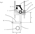
- the device for emptying garbage cans can be arranged at the dumping opening of a garbage collection container, which is not shown in detail. It has a lift truck 1, having a receiving device 2 in the form of a comb receptacle with a clamping rail 3 for receiving a garbage container (also not shown).
- the clamping rail 3 can be rotated about a clamping axis 4 in order to fix the refuse container on the receiving device 2 so that it cannot be lost.
- the lift truck 1 has a support 5 that supports the refuse container.
- a shaft 6 is rotatably mounted about an axis of rotation D, with a traction device 7 and a drive 8 for the traction device 7, which is arranged above the dumping opening, in order to drive the lifting truck 1 in a lifting movement and a rotary movement, with a lever 9 being arranged on the lifting truck 1, on which the traction device 7 acts.
- the traction means 7 is a rope or a chain, which has a motor-driven reel as the drive 8 .
- the lever 9 is spaced at a vertical distance V (see also 3 ) Arranged from the axis of rotation D on the truck 1 and has a point of application 10 on which the traction means 7 engages.
- Fig. 1a shows the time at the beginning of an emptying process.
- the truck 1 is in the lifting movement.
- the lifting movement is guided by a linear guide, which is formed from guide rods 11 and a carriage 12 attached to the lifting carriage 1 .
- the truck 1 swings out, which increases the lever arm for the rotary movement.
- the Figures 2a to 2d show the timing of an emptying process for a second embodiment of the invention.
- the same features of the device are denoted by the same reference numbers.
- This embodiment has two differences from the first embodiment.
- the lever 3 is articulated on the truck 1 .
- a stop 13 ensures that the lever 3 does not fold over towards the axis of rotation D as soon as the traction means 7 exerts a force on the lever 3 at the point of application 10 .
- the axis of rotation D or the shaft 6 is guided in a rail or on a cam (not shown in detail) and thus executes a curved path that enables the rotary movement of the truck 1 about the axis of rotation D.
- the point of attack 10 is only guided linearly upwards. This can also be done in a rail, for example.
- the articulated connection of the lever 3 to the truck 1 allows the distance between the axis of rotation D and the point of application 10 to be increased, but without the traction means being deflected from the vertical.
- the lever 3 folds down away from the rotary axis D.
- the horizontal distance H between the point of application 10 and the axis of rotation D and thus the lever arm for the rotary movement is increased.
- the truck 1 does not swing out.
- the traction means 7 remains essentially in a vertical orientation during the entire emptying cycle, so that an optimal power transmission is provided.
- the lever 3 is also arranged at a vertical distance V from the axis of rotation D.
- the vertical distance V of the point of application 10 to the axis of rotation D may not be identical to a vertical distance V of the point at which the lever 3 is arranged on the truck 1 to the axis of rotation.
Landscapes
- Engineering & Computer Science (AREA)
- Mechanical Engineering (AREA)
- Refuse-Collection Vehicles (AREA)
Applications Claiming Priority (1)
| Application Number | Priority Date | Filing Date | Title |
|---|---|---|---|
| DE102022101287.5A DE102022101287A1 (de) | 2022-01-20 | 2022-01-20 | Vorrichtung zum Entleeren von Müllbehältern |
Publications (1)
| Publication Number | Publication Date |
|---|---|
| EP4215459A1 true EP4215459A1 (fr) | 2023-07-26 |
Family
ID=86852288
Family Applications (1)
| Application Number | Title | Priority Date | Filing Date |
|---|---|---|---|
| EP23151242.7A Pending EP4215459A1 (fr) | 2022-01-20 | 2023-01-12 | Dispositif pour vider les poubelles |
Country Status (2)
| Country | Link |
|---|---|
| EP (1) | EP4215459A1 (fr) |
| DE (1) | DE102022101287A1 (fr) |
Cited By (2)
| Publication number | Priority date | Publication date | Assignee | Title |
|---|---|---|---|---|
| DE102024112827B3 (de) * | 2024-05-07 | 2025-09-04 | Zöller-Kipper Gesellschaft mit beschränkter Haftung | Hub-Kipp-Vorrichtung und Verfahren zum Betreiben einer Hub-Kipp-Vorrichtung |
| EP4686673A2 (fr) | 2024-08-02 | 2026-02-04 | Zöller-Kipper GmbH | Dispositif de levage et de basculement et procédé d'utilisation d'un dispositif de levage et de basculement |
Citations (2)
| Publication number | Priority date | Publication date | Assignee | Title |
|---|---|---|---|---|
| US2847135A (en) * | 1954-10-01 | 1958-08-12 | Victor A Galloway | Vehicle loader |
| WO2004083077A1 (fr) | 2003-03-17 | 2004-09-30 | Del Equipment (Uk) Limited | Mecanisme de levage destine a lever un receptacle |
Family Cites Families (5)
| Publication number | Priority date | Publication date | Assignee | Title |
|---|---|---|---|---|
| US1755547A (en) | 1925-04-11 | 1930-04-22 | Atia Sales Corp | Refuse collector |
| US2456434A (en) | 1945-12-01 | 1948-12-14 | Leach Corp | Self-loading vehicle |
| US2674384A (en) | 1951-11-28 | 1954-04-06 | Victor A Galloway | Vehicle loading equipment |
| GB960724A (en) | 1961-11-06 | 1964-06-17 | John Gibson & Son Ltd | Improvements in refuse collecting vehicles |
| AT227177B (de) | 1962-04-28 | 1963-05-10 | Heinrich Voelkl | Vorrichtung zum staubfreien Entleeren von Müllgefäßen |
-
2022
- 2022-01-20 DE DE102022101287.5A patent/DE102022101287A1/de active Pending
-
2023
- 2023-01-12 EP EP23151242.7A patent/EP4215459A1/fr active Pending
Patent Citations (2)
| Publication number | Priority date | Publication date | Assignee | Title |
|---|---|---|---|---|
| US2847135A (en) * | 1954-10-01 | 1958-08-12 | Victor A Galloway | Vehicle loader |
| WO2004083077A1 (fr) | 2003-03-17 | 2004-09-30 | Del Equipment (Uk) Limited | Mecanisme de levage destine a lever un receptacle |
Cited By (4)
| Publication number | Priority date | Publication date | Assignee | Title |
|---|---|---|---|---|
| DE102024112827B3 (de) * | 2024-05-07 | 2025-09-04 | Zöller-Kipper Gesellschaft mit beschränkter Haftung | Hub-Kipp-Vorrichtung und Verfahren zum Betreiben einer Hub-Kipp-Vorrichtung |
| EP4647365A1 (fr) | 2024-05-07 | 2025-11-12 | Zöller-Kipper GmbH | Dispositif de levage et de basculement et méthode d'utilisation d'un dispositif de levage et de basculement |
| EP4686673A2 (fr) | 2024-08-02 | 2026-02-04 | Zöller-Kipper GmbH | Dispositif de levage et de basculement et procédé d'utilisation d'un dispositif de levage et de basculement |
| DE102024122057A1 (de) * | 2024-08-02 | 2026-02-05 | Zöller-Kipper Gesellschaft mit beschränkter Haftung | Hub-Kipp-Vorrichtung und Verfahren zum Betreiben einer Hub-Kipp-Vorrichtung |
Also Published As
| Publication number | Publication date |
|---|---|
| DE102022101287A1 (de) | 2023-07-20 |
Similar Documents
| Publication | Publication Date | Title |
|---|---|---|
| DE2146653A1 (de) | Hubkipp- oder kippvorrichtung fuer grossraummuellbehaelter | |
| DE3830227A1 (de) | Hubkippvorrichtung zum entleeren von behaeltern in die einschuettoeffnung eines sammelbehaelters, insbesondere zum entleeren von muellbehaeltern in den sammelbehaelter eines muellfahrzeuges | |
| DE3888077T2 (de) | Greif-, Hub- und Kippvorrichtung zum Entleeren von Müllbehältern, wobei die Vorrichtung an der Seite eines Müllfahrzeuges angebracht ist. | |
| EP4215459A1 (fr) | Dispositif pour vider les poubelles | |
| DE102012100765A1 (de) | Steilförderanlage für den Tagebau | |
| EP3828104B1 (fr) | Unité d'entraînement pour un dispositif élévateur-culbuteur | |
| WO2020151849A1 (fr) | Dispositif de levage et de basculement destiné à un véhicule de collecte de déchets | |
| EP0579828A1 (fr) | Vehicule pour collecter et transporter des dechets | |
| EP0122493B1 (fr) | Dispositif pour soulever, puis basculer des récipients à ordures dans un véhicule de transport d'ordures | |
| EP1512631B1 (fr) | Dispositif de remplissage de sac | |
| DE2937727A1 (de) | Anlage zum verdichten von festkoerperladungen in einem behaelter | |
| DE2434540C2 (de) | Einrichtung zum automatischen Quertransport von Werkstücken auf mehrstufigen Umformpressen | |
| DE2205998A1 (de) | Trommelanlage zur oberflaechenbehandlung kleinerer metallgegenstaende | |
| DE19621962C2 (de) | Führerhaus für Richtungswechselbetrieb | |
| DE2203019C3 (de) | Haushalsmüllpresse mit Scherenhebelsystem zur Stempelbewegung | |
| DE29905551U1 (de) | Vorrichtung zum Transportieren und Entleeren von Abfall-Behältern | |
| DE1584646B1 (de) | Fahrbarer Drehkippbehaelter | |
| DD284150A5 (de) | Vorrichtung zum auflockern von schuettgut | |
| EP3530593B1 (fr) | Transporteur vertical pourvu de chaîne de poussée et maillon de chaîne, élément de transport et dispositif d'alimentation | |
| DE20015038U1 (de) | Abfallsammelfahrzeug | |
| EP0795493A1 (fr) | Installation stationnaire de chargement pour récipients collecteurs transportables | |
| DE2917919A1 (de) | Einrichtung zum giessen einer metallschmelze in giessformen | |
| DE69801390T2 (de) | Hub-Kippvorrichtung für Behälter und mit einer solchen Vorrichtung ausgestatteter Müllsammelbehälter | |
| DE60300290T2 (de) | Müllsammelfahrzeug | |
| CH687386A5 (de) | Hub-Kippvorrichtung fuer geteilte Kammschuettung bei Muellfahrzeugen. |
Legal Events
| Date | Code | Title | Description |
|---|---|---|---|
| PUAI | Public reference made under article 153(3) epc to a published international application that has entered the european phase |
Free format text: ORIGINAL CODE: 0009012 |
|
| STAA | Information on the status of an ep patent application or granted ep patent |
Free format text: STATUS: THE APPLICATION HAS BEEN PUBLISHED |
|
| AK | Designated contracting states |
Kind code of ref document: A1 Designated state(s): AL AT BE BG CH CY CZ DE DK EE ES FI FR GB GR HR HU IE IS IT LI LT LU LV MC ME MK MT NL NO PL PT RO RS SE SI SK SM TR |
|
| STAA | Information on the status of an ep patent application or granted ep patent |
Free format text: STATUS: REQUEST FOR EXAMINATION WAS MADE |
|
| 17P | Request for examination filed |
Effective date: 20240123 |
|
| RBV | Designated contracting states (corrected) |
Designated state(s): AL AT BE BG CH CY CZ DE DK EE ES FI FR GB GR HR HU IE IS IT LI LT LU LV MC ME MK MT NL NO PL PT RO RS SE SI SK SM TR |