EP4215754A1 - Dispositif de moteur à stator chemisé - Google Patents
Dispositif de moteur à stator chemisé Download PDFInfo
- Publication number
- EP4215754A1 EP4215754A1 EP22153205.4A EP22153205A EP4215754A1 EP 4215754 A1 EP4215754 A1 EP 4215754A1 EP 22153205 A EP22153205 A EP 22153205A EP 4215754 A1 EP4215754 A1 EP 4215754A1
- Authority
- EP
- European Patent Office
- Prior art keywords
- groove
- rotor
- impeller
- protrusion
- axis
- Prior art date
- Legal status (The legal status is an assumption and is not a legal conclusion. Google has not performed a legal analysis and makes no representation as to the accuracy of the status listed.)
- Granted
Links
Images




Classifications
-
- F—MECHANICAL ENGINEERING; LIGHTING; HEATING; WEAPONS; BLASTING
- F04—POSITIVE - DISPLACEMENT MACHINES FOR LIQUIDS; PUMPS FOR LIQUIDS OR ELASTIC FLUIDS
- F04D—NON-POSITIVE-DISPLACEMENT PUMPS
- F04D13/00—Pumping installations or systems
- F04D13/02—Units comprising pumps and their driving means
- F04D13/06—Units comprising pumps and their driving means the pump being electrically driven
- F04D13/0606—Canned motor pumps
-
- F—MECHANICAL ENGINEERING; LIGHTING; HEATING; WEAPONS; BLASTING
- F04—POSITIVE - DISPLACEMENT MACHINES FOR LIQUIDS; PUMPS FOR LIQUIDS OR ELASTIC FLUIDS
- F04D—NON-POSITIVE-DISPLACEMENT PUMPS
- F04D29/00—Details, component parts, or accessories
- F04D29/18—Rotors
- F04D29/20—Mounting rotors on shafts
-
- F—MECHANICAL ENGINEERING; LIGHTING; HEATING; WEAPONS; BLASTING
- F16—ENGINEERING ELEMENTS AND UNITS; GENERAL MEASURES FOR PRODUCING AND MAINTAINING EFFECTIVE FUNCTIONING OF MACHINES OR INSTALLATIONS; THERMAL INSULATION IN GENERAL
- F16D—COUPLINGS FOR TRANSMITTING ROTATION; CLUTCHES; BRAKES
- F16D1/00—Couplings for rigidly connecting two coaxial shafts or other movable machine elements
- F16D1/10—Quick-acting couplings in which the parts are connected by simply bringing them together axially
- F16D1/108—Quick-acting couplings in which the parts are connected by simply bringing them together axially having retaining means rotating with the coupling and acting by interengaging parts, i.e. positive coupling
- F16D1/116—Quick-acting couplings in which the parts are connected by simply bringing them together axially having retaining means rotating with the coupling and acting by interengaging parts, i.e. positive coupling the interengaging parts including a continuous or interrupted circumferential groove in the surface of one of the coupling parts
-
- H—ELECTRICITY
- H02—GENERATION; CONVERSION OR DISTRIBUTION OF ELECTRIC POWER
- H02K—DYNAMO-ELECTRIC MACHINES
- H02K7/00—Arrangements for handling mechanical energy structurally associated with dynamo-electric machines, e.g. structural association with mechanical driving motors or auxiliary dynamo-electric machines
- H02K7/003—Couplings; Details of shafts
-
- F—MECHANICAL ENGINEERING; LIGHTING; HEATING; WEAPONS; BLASTING
- F05—INDEXING SCHEMES RELATING TO ENGINES OR PUMPS IN VARIOUS SUBCLASSES OF CLASSES F01-F04
- F05D—INDEXING SCHEME FOR ASPECTS RELATING TO NON-POSITIVE-DISPLACEMENT MACHINES OR ENGINES, GAS-TURBINES OR JET-PROPULSION PLANTS
- F05D2260/00—Function
- F05D2260/30—Retaining components in desired mutual position
- F05D2260/36—Retaining components in desired mutual position by a form fit connection, e.g. by interlocking
-
- F—MECHANICAL ENGINEERING; LIGHTING; HEATING; WEAPONS; BLASTING
- F16—ENGINEERING ELEMENTS AND UNITS; GENERAL MEASURES FOR PRODUCING AND MAINTAINING EFFECTIVE FUNCTIONING OF MACHINES OR INSTALLATIONS; THERMAL INSULATION IN GENERAL
- F16D—COUPLINGS FOR TRANSMITTING ROTATION; CLUTCHES; BRAKES
- F16D1/00—Couplings for rigidly connecting two coaxial shafts or other movable machine elements
- F16D1/10—Quick-acting couplings in which the parts are connected by simply bringing them together axially
- F16D2001/103—Quick-acting couplings in which the parts are connected by simply bringing them together axially the torque is transmitted via splined connections
Definitions
- the disclosure relates to a canned motor device, and more particularly to a canned motor device that includes a rotor assembly with enhanced stability when in operation.
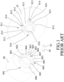
- a conventional canned motor device disclosed in Taiwanese Patent No. 507049 includes a magnetic rotor 80, an impeller 81 and two pins 82.
- the impeller 81 has a rotor coupling section 811 that surrounds an imaginary axis, and that has an outer surrounding surface 812, a plurality of impeller protrusions 813 and a plurality of impeller grooves 814.
- the impeller protrusions 813 are angularly spaced apart from each other about the imaginary axis and protrude from the outer surrounding surface 812.
- the impeller grooves 814 are angularly spaced apart from each other about the imaginary axis.
- Each of the impeller protrusions 813 has two impeller lateral surfaces 815 each of which is connected to the outer surrounding surface 812 and extends parallelly to the imaginary axis.
- Each of the impeller lateral surfaces 815 cooperates with the outer surrounding surface 812 and one of the impeller lateral surfaces 815 of one of the impeller protrusions 813 that is adjacent thereto to define a respective one of the impeller grooves 814 (i.e., each of the impeller grooves 814 is located between two adjacent ones of the impeller protrusions 813).
- the magnetic rotor 80 has an impeller coupling section 801 that is coupled to the rotor coupling section 811 of the impeller 81, that surrounds the imaginary axis, and that has an inner surrounding surface 802, a plurality of rotor protrusions 803 and a plurality of rotor grooves 804.
- Each of the rotor protrusions 803 has two rotor lateral surfaces 805 each of which is connected to the inner surrounding surface 802 and extends parallelly to the imaginary axis.
- Each of the rotor lateral surfaces 805 cooperates with the inner surrounding surface 802 and one of the rotor lateral surfaces 805 of one of the rotor protrusions 803 that is adjacent thereto to define a respective one of the rotor grooves 804 (i.e., each of the rotor grooves 804 is located between two adjacent ones of the rotor protrusions 803).
- the magnetic rotor 80 is operable to drive the impeller 81 to co-rotate, via the rotor lateral surfaces 805 thereof and the impeller lateral surfaces 815 of the impeller 81, so that the conventional canned motor device may pump liquid.
- the rotor lateral surfaces 805 of the magnetic rotor 80 and the impeller lateral surfaces 815 of the impeller 81 may not prevent the magnetic rotor 80 and the impeller 81 from separating from each other in a direction of the imaginary axis when the conventional canned motor device is in operation.
- the rotor coupling section 811 of the impeller 81 is formed with two impeller holes 816
- the impeller coupling section 801 of the magnetic rotor 80 is formed with two rotor holes 806 that respectively correspond in position to the impeller holes 816.
- each of the pins 82 extends through a respective one of the impeller holes 816 and the respective one of the rotor holes 806 to interconnect the impeller 81 and the magnetic rotor 80.
- this configuration of the conventional canned motor device is relatively complex and makes the conventional canned motor device difficult to assemble.
- an object of the disclosure is to provide a rotor assembly that can alleviate the drawback of the prior art.
- the rotor assembly includes an inner rotor and an impeller.
- the inner rotor has a first section, a second section and a shoulder portion.
- the first section has a rotor end surface, an outer surface, a plurality of protrusions and a plurality of engaging grooves.
- the outer surface surrounds an axis and is connected to the rotor end surface.
- the protrusions are angularly spaced apart from each other about the axis and protrude from the outer surface.
- the engaging grooves are angularly spaced apart from each other about the axis and are indented from the outer surface.
- the second section is located at one side of the outer surface opposite to the rotor end surface and is connected to the first section in a direction of the axis.
- the shoulder portion interconnects the first section and the second section.
- Each of the protrusions extends from the rotor end surface to the shoulder portion, and has a first protrusion end and a second protrusion end that are respectively adjacent to the rotor end surface and the shoulder portion, and at least one lateral protrusion surface that extends from the first protrusion end to the second protrusion end, and that is oblique to the axis.
- the second protrusion end has a width in a circumferential direction of the inner rotor greater than that of the first protrusion end.
- the impeller has a connecting section and a vane section.
- the connecting section is coupled to the first section of the inner rotor, and has a shoulder facing surface, an inner surrounding surface, an outer surrounding surface, a plurality of inner grooves, a plurality of pairs of slots and a plurality of engaging hooks.
- the shoulder facing surface corresponds in position to the shoulder portion of the inner rotor.
- the inner surrounding surface surrounds the axis and defines an accommodating hole.
- the outer surrounding surface is opposite to the inner surrounding surface.
- Each of the inner grooves is indented from the inner surrounding surface, is formed through the shoulder facing surface and has a first groove end that is adjacent to the shoulder facing surface, and a second groove end that is opposite to the first groove end along the axis.
- the first groove end has a width in a circumferential direction of the impeller greater than that of the second groove end.
- Each of the slots is indented from the shoulder facing surface and is formed through the inner surrounding surface and the outer surrounding surface.
- Each of the engaging hooks is located between a respective one pair of the slots.
- the vane section is connected to the connecting section in the direction of the axis.
- Each of the inner grooves is defined by a main groove surface, two lateral groove surfaces and a groove end surface.
- the main groove surface of each of the inner grooves is located radially between the inner surrounding surface and the outer surrounding surface.
- Each of the lateral groove surfaces of each of the inner grooves interconnects the main groove surface of the inner groove and the inner surrounding surface, and extends from the first groove end to the second groove end.
- each of the inner grooves interconnects the main groove surface, the lateral groove surfaces and the inner surrounding surface and is located at the second groove end. At least one of the lateral groove surfaces is oblique to the axis.
- Each of the protrusions of the inner rotor has a largest width in the circumferential direction of the inner rotor greater than a smallest width of a respective one of the inner grooves of the impeller in the circumferential direction of the impeller so that when the engaging hooks of the impeller respectively engage the engaging grooves of the inner rotor, the protrusions of the inner rotor respectively engage the inner grooves of the impeller in a manner that the at least one lateral protrusion surface of each of the protrusions urges one of the lateral groove surfaces of the respective one of the inner grooves.
- Another object of the disclosure is to provide a canned motor device that can alleviate the drawback of the prior art.
- the canned motor device includes a base, a fixed seat, a motor unit, a first cover and a second cover.
- the base is formed in a shape of a hollow cylinder that surrounds an axis, and defines an accommodating space.
- the fixed seat is formed in a shape of a hollow cylinder that surrounds the axis, and is disposed in the accommodating space.
- the motor unit includes a case body, a stator, an inner rotor and an impeller.
- the case body is disposed on the base.
- the stator is sleeved on the case body and is surrounded by the fixed seat.
- the inner rotor is disposed in the case body and has a first section, a second section and a shoulder portion.
- the first section has a rotor end surface, an outer surface, a plurality of protrusions and a plurality of engaging grooves.
- the outer surface surrounds an axis and is connected to the rotor end surface.
- the protrusions are angularly spaced apart from each other about the axis and protrude from the outer surface.
- the engaging grooves are angularly spaced apart from each other about the axis and are indented from the outer surface.
- the second section is located at one side of the outer surface opposite to the rotor end surface and is connected to the first section in a direction of the axis.
- the shoulder portion interconnects the first section and the second section.
- Each of the protrusions extends from the rotor end surface to the shoulder portion, and has a first protrusion end and a second protrusion end that are respectively adjacent to the rotor end surface and the shoulder portion, and at least one lateral protrusion surface that extends from the first protrusion end to the second protrusion end, and that is oblique to the axis.
- the second protrusion end has a width in a circumferential direction of the inner rotor greater than that of the first protrusion end.
- the impeller has a connecting section and a vane section.
- the connecting section is coupled to the first section of the inner rotor, and has a shoulder facing surface, an inner surrounding surface, an outer surrounding surface, a plurality of inner grooves, a plurality of pairs of slots and a plurality of engaging hooks.
- the shoulder facing surface corresponds in position to the shoulder portion of the inner rotor.
- the inner surrounding surface surrounds the axis and defines an accommodating hole.
- the outer surrounding surface is opposite to the inner surrounding surface.
- Each of the inner grooves is indented from the inner surrounding surface, is formed through the shoulder facing surface and has a first groove end that is adjacent to the shoulder facing surface, and a second groove end that is opposite to the first groove end along the axis.
- the first groove end has a width in a circumferential direction of the impeller greater than that of the second groove end.
- Each of the slots is indented from the shoulder facing surface and is formed through the inner surrounding surface and the outer surrounding surface.
- Each of the engaging hooks is located between a respective one pair of the slots.
- the vane section is connected to the connecting section in the direction of the axis.
- Each of the inner grooves is defined by a main groove surface, two lateral groove surfaces and a groove end surface.
- the main groove surface of each of the inner grooves is located radially between the inner surrounding surface and the outer surrounding surface.
- Each of the lateral groove surfaces of each of the inner grooves interconnects the main groove surface of the inner groove and the inner surrounding surface, and extends from the first groove end to the second groove end.
- each of the inner grooves interconnects the main groove surface, the lateral groove surfaces and the inner surrounding surface and is located at the second groove end. At least one of the lateral groove surfaces is oblique to the axis.
- the first cover is disposed on the base and covers the impeller.
- the second cover is located at one side of the base opposite to the first cover along the axis, and is fixedly mounted to the base.
- Each of the protrusions of the inner rotor has a largest width in the circumferential direction of the inner rotor greater than a smallest width of a respective one of the inner grooves of the impeller in the circumferential direction of the impeller so that when the engaging hooks of the impeller respectively engage the engaging grooves of the inner rotor, the protrusions of the inner rotor respectively engage the inner grooves of the impeller in a manner that the at least one lateral protrusion surface of each of the protrusions urges one of the lateral groove surfaces of the respective one of the inner grooves.
- an embodiment of a canned motor device includes a base 10, a fixed seat 20, a motor unit 30, a first cover 60 and a second cover 70.
- the base 10 is made of a plastic material and is formed in a shape of a hollow cylinder that surrounds an axis (L).
- the plastic material may be an engineering plastic with acid and alkali resistance, such as polypropylene (PP), glass fiber reinforced polypropylene (GFRPP), polyvinylidene difluoride (PVDF) and carbon fiber filled ethylene tetrafluoroethylene (CFRETFE).
- PP polypropylene
- GFRPP glass fiber reinforced polypropylene
- PVDF polyvinylidene difluoride
- CFRETFE carbon fiber filled ethylene tetrafluoroethylene
- the base 10 defines an accommodating space 11 through which the axis (L) extends.
- the fixed seat 20 is made of an aluminum alloy, is formed in a shape of a hollow cylinder that surrounds the axis (L), and is non-rotatably disposed in the accommodating space 11 of the base 10.
- the motor unit 30 includes a case body 31, a stator 32, an inner rotor 40 and an impeller 50.
- the case body 31 is disposed on the base 10.
- the stator 32 is sleeved on the case body 31 and is surrounded by the fixed seat 20.
- the inner rotor 40 is disposed in the case body 31.
- the impeller 50 is connected to the inner rotor 40 in a manner that the impeller 50 and the inner rotor 40 are assembled to form a rotor assembly. Since the relevant features of this disclosure do not concern the specific operation of the motor unit 30, further details of the same are omitted herein for the sake of brevity, and only the configuration of the rotor assembly that includes the inner rotor 40 and the impeller 50 is described in the following description.
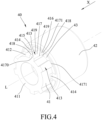
- the inner rotor 40 includes a first section 41, a second section 42 and a shoulder portion 43.
- the first section 41 has a rotor end surface 411, an outer surface 412, a plurality of protrusions 413 and a plurality of engaging grooves 414.
- the outer surface 412 surrounds the axis (L), and is connected to the rotor end surface 411.
- the protrusions 413 are angularly spaced apart from each other about the axis (L) and protrude from the outer surface 412.
- the engaging grooves 414 are angularly spaced apart from each other about the axis (L) and are indented from the outer surface 412.
- the second section 42 is located at one side of the outer surface 412 opposite to the rotor end surface 411 and is connected to the first section 41 in a direction (X) of the axis (L).
- the shoulder portion 43 interconnects the first section 41 and the second section 42.
- the outer surface 412 is configured to be frustoconical and tapers toward the rotor end surface 411.
- Each of the protrusions 413 extends from the rotor end surface 411 to the shoulder portion 43, and has a first protrusion end 415, a second protrusion end 416, a main protrusion surface 417 and two lateral protrusion surfaces 418.
- the first protrusion end 415 and the second protrusion end 416 are respectively adjacent to the rotor end surface 411 and the shoulder portion 43.
- the second protrusion end 416 has a width in a circumferential direction of the inner rotor 40 greater than that of the first protrusion end 415.
- the main protrusion surface 417 is spaced apart from the outer surface 412.
- Each of the lateral protrusion surfaces 418 extends from the first protrusion end 415 to the second protrusion end 416, and is oblique to the axis (L). Specifically, in this embodiment, the angle between the axis (L) and the normal vector of each of the lateral protrusion surfaces 418 ranges from 87 to 88 degrees.
- the main protrusion surface 417 is substantially configured to be in the shape of a trapezoid, and has two lateral protrusion edges 419, a first protrusion edge 4170 and a second protrusion edge 4171.
- the lateral protrusion edges 419 are angularly spaced apart from each other about the axis (L).
- the first protrusion edge 4170 interconnects the lateral protrusion edges 419 and is adjacent to the rotor end surface 411 of the first section 41.
- the second protrusion edge 4171 is spaced apart from the first protrusion edge 4170 along the axis (L), interconnects the lateral protrusion edges 419, and is adjacent to the shoulder portion 43.
- each of the lateral protrusion surfaces 418 interconnects the outer surface 412 of the first section 41 and a respective one of the lateral protrusion edges 419 of the main protrusion surface 417.
- the shape of the trapezoid in which the main protrusion surface 417 is configured to be is defined by the lateral protrusion edges 419, the first protrusion edge 4170 and the second protrusion edge 4171.
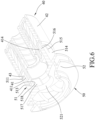
- the impeller 50 has a connecting section 51 and a vane section 52 that is connected to the connecting section 51 in the direction (X) of the axis (L).
- the connecting section 51 is coupled to the first section 41 of the inner rotor 40, and has a shoulder facing surface 511, an inner surrounding surface 513, an outer surrounding surface 514, a plurality of inner grooves 54, an abutting portion 517, a plurality of pairs of slots 515, and a plurality of engaging hooks 516.
- the shoulder facing surface 511 corresponds in position to the shoulder portion 43 of the inner rotor 40.
- the inner surrounding surface 513 is connected to the shoulder facing surface 511, surrounds the axis (L) and defines an accommodating hole 512.
- the outer surrounding surface 514 is opposite to the inner surrounding surface 513.
- Each of the inner grooves 54 is indented from the inner surrounding surface 513, is formed through the shoulder facing surface 511, and has a first groove end 540 and a second groove end 541.
- the first groove end 540 is adjacent to the shoulder facing surface 511
- the second groove end 541 is opposite to the first groove end 540 along the axis (L).
- the inner surrounding surface 513 is configured to be frustoconical and tapers from the shoulder facing surface 511 toward the vane section 52, and the first groove end 540 has a width in a circumferential direction of the impeller 50 greater than that of the second groove end 541.
- the abutting portion 517 is located between the vane section 52 and the inner grooves 54, protrudes from the inner surrounding surface 513, and has an abutting surface 518 that is adjacent to the second groove ends 541 of the inner grooves 54.
- Each of the slots 515 is indented from the shoulder facing surface 511 and is formed through the inner surrounding surface 513 and the outer surrounding surface 514.
- Each of the engaging hooks 516 is located between a respective one pair of the slots 515.
- Each of the inner grooves 54 is defined by a main groove surface 542, two lateral groove surfaces 544 and a groove end surface 543.
- the main groove surface 542 of each of the inner grooves 54 is located radially between the inner surrounding surface 513 and the outer surrounding surface 514.
- each of the lateral groove surfaces 544 of each of the inner grooves 54 interconnects the main groove surface 542 of the inner groove 54 and the inner surrounding surface 513, and extends from the first groove end 540 to the second groove end 541.
- the groove end surface 543 of each of the inner grooves 54 interconnects the main groove surface 542, the lateral groove surfaces 544 and the inner surrounding surface 513, and is located at the second groove end 541.
- each of the lateral groove surfaces 544 is oblique to the axis (L). Specifically, the angle between the axis (L) and the normal vector of each of the lateral groove surfaces 544 ranges from 87 to 88 degrees.
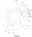
- the main groove surface 542 of each of the inner grooves 54 is substantially configured to be in the shape of a trapezoid, and has two lateral groove edges 545, a first groove edge 546 and a second groove edge 547.
- the lateral groove edges 545 are angularly spaced apart from each other about the axis (L).
- the first groove edge 546 interconnects the lateral groove edges 545 and is adjacent to the second groove end 541.
- the second groove edge 547 is spaced apart from the first groove edge 546 along the axis (L), interconnects the lateral groove edges 545, and is adjacent to the first groove end 540.
- the shape of the trapezoid in which the main groove surface 542 is configured to be is defined by the lateral groove edges 545, the first groove edge 546 and the second groove edge 547.
- the inner rotor 40 and the impeller 50 are coupled along the axis (L) in a manner that the inner rotor 40 and the impeller 50 are moved toward each other along the axis (L) to respectively engage the engaging hooks 516 of the impeller 50 with the engaging grooves 414 of the inner rotor 40.
- Each of the protrusions 413 of the inner rotor 40 has a largest width in the circumferential direction of the inner rotor 40 greater than a smallest width of a respective one of the inner grooves 54 of the impeller 50 in the circumferential direction of the impeller 50 so that when the engaging hooks 516 of the impeller 50 respectively engage the engaging grooves 414 of the inner rotor 40, the protrusions 413 of the inner rotor 40 respectively engage the inner grooves 54 of the impeller 50 in a manner that each of the lateral protrusion surfaces 418 of each of the protrusions 413 urges a respective one of the lateral groove surfaces 544 of the respective one of the inner grooves 54.
- the first cover 60 is disposed on the base 10 in the direction (X) of the axis (L), and covers the impeller 50. Specifically, the first cover 60 is fixedly mounted to the base 10 by a plurality of screws, and has an intake opening 601 at an end thereof along the axis (L), and an exit opening 602 located at one side of the intake opening 601 that is the same as the impeller 50 and extending along a tangent line (not shown) to the outer periphery of the impeller 50.
- the second cover 70 is located at one side of the base 10 opposite to the first cover 60 along the axis (L), is fixedly mounted to the base 10 by a plurality of screws, and has an inner cover surface 71 (see Figure 2 ) that abuts against one end of the case body 31 of the motor unit 30.
- the inner rotor 40 of the motor unit 30 is driven by the stator 32 to rotate and to further drive the impeller 50 of the motor unit 30 to co-rotate so that the embodiment may pump liquid in a manner that the liquid is moved into the canned motor device through the intake opening 601 and is moved toward the exit opening 602 by the impeller 50 to exit the canned motor device through the exit opening 602.
- the connecting section 51 of the impeller 50 is resiliently deformable.
- external forces are applied on the inner rotor 40 and the impeller 50 such that the inner rotor 40 and the impeller 50 are pushed against each other, and that the connecting section 51 is deformed radially outwardly about the axis (L).
- the connecting section 51 restores to its original shape and pushes the inner rotor 40 away from the the impeller 50, so that the inner rotor 40 and the impeller 50 move away from each other and that each of the engaging hooks 516 tightly engages the respective one of the engaging grooves 414 of the inner rotor 40.
- the engaging hooks 516 restrain the impeller 50 from being separated from the inner rotor 40 in the direction (X) of the axis (L) .
- the outer surface 412 of the inner rotor 40 and the inner surrounding surface 513 of the impeller 50 being configured to be frustoconical and tapering in the same direction, the outer surface 412 urges the inner surrounding surface 513 when the rotor assembly is assembled, and it may be easier to align the connecting section 51 of the impeller 50 with the first section 41 of the inner rotor 40.
- each of the lateral protrusion surfaces 418 of each of the protrusions 413 of the inner rotor 40 and each of the lateral groove surfaces 544 of each of the inner grooves 54 of the impeller 50 being oblique to the axis (L)
- the lateral protrusion surfaces 418 of the inner rotor 40 respectively urging the lateral groove surfaces 544 of the impeller 50 gaps between the inner rotor 40 and the impeller 50 are minimized when the inner rotor 40 and the impeller 50 are coupled. Therefore, the stability of the impeller 50 is enhanced when in operation.
- the canned motor device of the disclosure offers a design that is easy to assemble while providing the rotor assembly that includes the inner rotor 40 and the impeller 50 with enhanced stability.
Landscapes
- Engineering & Computer Science (AREA)
- General Engineering & Computer Science (AREA)
- Mechanical Engineering (AREA)
- Power Engineering (AREA)
- Structures Of Non-Positive Displacement Pumps (AREA)
Priority Applications (1)
| Application Number | Priority Date | Filing Date | Title |
|---|---|---|---|
| EP22153205.4A EP4215754B1 (fr) | 2022-01-25 | 2022-01-25 | Dispositif de moteur à stator chemisé |
Applications Claiming Priority (1)
| Application Number | Priority Date | Filing Date | Title |
|---|---|---|---|
| EP22153205.4A EP4215754B1 (fr) | 2022-01-25 | 2022-01-25 | Dispositif de moteur à stator chemisé |
Publications (2)
| Publication Number | Publication Date |
|---|---|
| EP4215754A1 true EP4215754A1 (fr) | 2023-07-26 |
| EP4215754B1 EP4215754B1 (fr) | 2024-12-11 |
Family
ID=80035261
Family Applications (1)
| Application Number | Title | Priority Date | Filing Date |
|---|---|---|---|
| EP22153205.4A Active EP4215754B1 (fr) | 2022-01-25 | 2022-01-25 | Dispositif de moteur à stator chemisé |
Country Status (1)
| Country | Link |
|---|---|
| EP (1) | EP4215754B1 (fr) |
Citations (6)
| Publication number | Priority date | Publication date | Assignee | Title |
|---|---|---|---|---|
| TW507049B (en) | 2001-06-05 | 2002-10-21 | Iwaki Co Ltd | Magnetic pump |
| EP1340917A1 (fr) * | 2001-06-05 | 2003-09-03 | IWAKI Co., Ltd. | Pompe a entrainement magnetique |
| US20140209323A1 (en) * | 2013-01-29 | 2014-07-31 | Schlumberger Technology Corporation | Collet coupling for electric submersible pump shafts |
| DE102014220377A1 (de) * | 2014-10-08 | 2016-04-14 | Mahle International Gmbh | Hybrid-Kühlmittelpumpe |
| US20180258944A1 (en) * | 2017-03-08 | 2018-09-13 | Mahle International Gmbh | Liquid pump |
| US20220018349A1 (en) * | 2020-07-20 | 2022-01-20 | World Chemical Co., Ltd. | Magnetic pump and rotary body for the magnetic pump |
-
2022
- 2022-01-25 EP EP22153205.4A patent/EP4215754B1/fr active Active
Patent Citations (6)
| Publication number | Priority date | Publication date | Assignee | Title |
|---|---|---|---|---|
| TW507049B (en) | 2001-06-05 | 2002-10-21 | Iwaki Co Ltd | Magnetic pump |
| EP1340917A1 (fr) * | 2001-06-05 | 2003-09-03 | IWAKI Co., Ltd. | Pompe a entrainement magnetique |
| US20140209323A1 (en) * | 2013-01-29 | 2014-07-31 | Schlumberger Technology Corporation | Collet coupling for electric submersible pump shafts |
| DE102014220377A1 (de) * | 2014-10-08 | 2016-04-14 | Mahle International Gmbh | Hybrid-Kühlmittelpumpe |
| US20180258944A1 (en) * | 2017-03-08 | 2018-09-13 | Mahle International Gmbh | Liquid pump |
| US20220018349A1 (en) * | 2020-07-20 | 2022-01-20 | World Chemical Co., Ltd. | Magnetic pump and rotary body for the magnetic pump |
Also Published As
| Publication number | Publication date |
|---|---|
| EP4215754B1 (fr) | 2024-12-11 |
Similar Documents
| Publication | Publication Date | Title |
|---|---|---|
| US7654792B2 (en) | Blower | |
| US4474077A (en) | Housing retaining means for portable power tools and method of assembly therefor | |
| KR19990067185A (ko) | 냉각팬과 모터용 비틀림 잠금부착 시스템 | |
| KR20210120942A (ko) | 모터 | |
| US20020122731A1 (en) | Monodirectional impeller for centrifugal electric pumps having a permanent-magnet synchronous motor | |
| CN101520057A (zh) | 轴流风扇单元 | |
| EP4215754A1 (fr) | Dispositif de moteur à stator chemisé | |
| KR101926474B1 (ko) | 워터 펌프 | |
| WO2018153350A1 (fr) | Roue à ailettes et pompe électrique | |
| US11664702B1 (en) | Canned motor device | |
| US7357686B2 (en) | Boat propeller with adjustable blades for adjusting the pitch thereof | |
| CN216199214U (zh) | 叶轮及内转子的组合体与罐装磁力泵 | |
| EP2149713B1 (fr) | Ventilateur à flux axial | |
| CN107035717A (zh) | 一种水泵叶轮及其制备方法 | |
| US20050191178A1 (en) | Assembly including an electric motor and a load | |
| KR102652192B1 (ko) | 캔드 모터 장치 | |
| EP3677780A1 (fr) | Pompe à huile | |
| EP4083440B1 (fr) | Dispositif de pale de ventilateur | |
| US11181119B2 (en) | Impeller and water pump having the same | |
| EP4109718B1 (fr) | Dispositif de moteur à gaine | |
| US6800975B2 (en) | Electric motor shaft access cover | |
| KR200497366Y1 (ko) | 캔드 모터 펌프 | |
| CN221195487U (zh) | 一种高扬程水泵双叶轮及自吸式离心泵 | |
| CN217080876U (zh) | 用于风扇的叶轮以及风扇 | |
| CN224049583U (zh) | 一种用于电控硅油离合器的阀片 |
Legal Events
| Date | Code | Title | Description |
|---|---|---|---|
| PUAI | Public reference made under article 153(3) epc to a published international application that has entered the european phase |
Free format text: ORIGINAL CODE: 0009012 |
|
| STAA | Information on the status of an ep patent application or granted ep patent |
Free format text: STATUS: REQUEST FOR EXAMINATION WAS MADE |
|
| 17P | Request for examination filed |
Effective date: 20230119 |
|
| AK | Designated contracting states |
Kind code of ref document: A1 Designated state(s): AL AT BE BG CH CY CZ DE DK EE ES FI FR GB GR HR HU IE IS IT LI LT LU LV MC MK MT NL NO PL PT RO RS SE SI SK SM TR |
|
| GRAP | Despatch of communication of intention to grant a patent |
Free format text: ORIGINAL CODE: EPIDOSNIGR1 |
|
| STAA | Information on the status of an ep patent application or granted ep patent |
Free format text: STATUS: GRANT OF PATENT IS INTENDED |
|
| INTG | Intention to grant announced |
Effective date: 20240712 |
|
| GRAS | Grant fee paid |
Free format text: ORIGINAL CODE: EPIDOSNIGR3 |
|
| GRAA | (expected) grant |
Free format text: ORIGINAL CODE: 0009210 |
|
| STAA | Information on the status of an ep patent application or granted ep patent |
Free format text: STATUS: THE PATENT HAS BEEN GRANTED |
|
| P01 | Opt-out of the competence of the unified patent court (upc) registered |
Free format text: CASE NUMBER: APP_55803/2024 Effective date: 20241011 |
|
| AK | Designated contracting states |
Kind code of ref document: B1 Designated state(s): AL AT BE BG CH CY CZ DE DK EE ES FI FR GB GR HR HU IE IS IT LI LT LU LV MC MK MT NL NO PL PT RO RS SE SI SK SM TR |
|
| REG | Reference to a national code |
Ref country code: GB Ref legal event code: FG4D |
|
| REG | Reference to a national code |
Ref country code: CH Ref legal event code: EP |
|
| REG | Reference to a national code |
Ref country code: DE Ref legal event code: R096 Ref document number: 602022008502 Country of ref document: DE |
|
| REG | Reference to a national code |
Ref country code: IE Ref legal event code: FG4D |
|
| REG | Reference to a national code |
Ref country code: LT Ref legal event code: MG9D |
|
| PG25 | Lapsed in a contracting state [announced via postgrant information from national office to epo] |
Ref country code: HR Free format text: LAPSE BECAUSE OF FAILURE TO SUBMIT A TRANSLATION OF THE DESCRIPTION OR TO PAY THE FEE WITHIN THE PRESCRIBED TIME-LIMIT Effective date: 20241211 |
|
| PG25 | Lapsed in a contracting state [announced via postgrant information from national office to epo] |
Ref country code: FI Free format text: LAPSE BECAUSE OF FAILURE TO SUBMIT A TRANSLATION OF THE DESCRIPTION OR TO PAY THE FEE WITHIN THE PRESCRIBED TIME-LIMIT Effective date: 20241211 |
|
| PG25 | Lapsed in a contracting state [announced via postgrant information from national office to epo] |
Ref country code: BG Free format text: LAPSE BECAUSE OF FAILURE TO SUBMIT A TRANSLATION OF THE DESCRIPTION OR TO PAY THE FEE WITHIN THE PRESCRIBED TIME-LIMIT Effective date: 20241211 |
|
| REG | Reference to a national code |
Ref country code: NL Ref legal event code: MP Effective date: 20241211 |
|
| PG25 | Lapsed in a contracting state [announced via postgrant information from national office to epo] |
Ref country code: ES Free format text: LAPSE BECAUSE OF FAILURE TO SUBMIT A TRANSLATION OF THE DESCRIPTION OR TO PAY THE FEE WITHIN THE PRESCRIBED TIME-LIMIT Effective date: 20241211 |
|
| PG25 | Lapsed in a contracting state [announced via postgrant information from national office to epo] |
Ref country code: NO Free format text: LAPSE BECAUSE OF FAILURE TO SUBMIT A TRANSLATION OF THE DESCRIPTION OR TO PAY THE FEE WITHIN THE PRESCRIBED TIME-LIMIT Effective date: 20250311 |
|
| PG25 | Lapsed in a contracting state [announced via postgrant information from national office to epo] |
Ref country code: LV Free format text: LAPSE BECAUSE OF FAILURE TO SUBMIT A TRANSLATION OF THE DESCRIPTION OR TO PAY THE FEE WITHIN THE PRESCRIBED TIME-LIMIT Effective date: 20241211 Ref country code: GR Free format text: LAPSE BECAUSE OF FAILURE TO SUBMIT A TRANSLATION OF THE DESCRIPTION OR TO PAY THE FEE WITHIN THE PRESCRIBED TIME-LIMIT Effective date: 20250312 |
|
| PG25 | Lapsed in a contracting state [announced via postgrant information from national office to epo] |
Ref country code: RS Free format text: LAPSE BECAUSE OF FAILURE TO SUBMIT A TRANSLATION OF THE DESCRIPTION OR TO PAY THE FEE WITHIN THE PRESCRIBED TIME-LIMIT Effective date: 20250311 |
|
| PG25 | Lapsed in a contracting state [announced via postgrant information from national office to epo] |
Ref country code: NL Free format text: LAPSE BECAUSE OF FAILURE TO SUBMIT A TRANSLATION OF THE DESCRIPTION OR TO PAY THE FEE WITHIN THE PRESCRIBED TIME-LIMIT Effective date: 20241211 |
|
| REG | Reference to a national code |
Ref country code: AT Ref legal event code: MK05 Ref document number: 1750569 Country of ref document: AT Kind code of ref document: T Effective date: 20241211 |
|
| PG25 | Lapsed in a contracting state [announced via postgrant information from national office to epo] |
Ref country code: SM Free format text: LAPSE BECAUSE OF FAILURE TO SUBMIT A TRANSLATION OF THE DESCRIPTION OR TO PAY THE FEE WITHIN THE PRESCRIBED TIME-LIMIT Effective date: 20241211 |
|
| PG25 | Lapsed in a contracting state [announced via postgrant information from national office to epo] |
Ref country code: PL Free format text: LAPSE BECAUSE OF FAILURE TO SUBMIT A TRANSLATION OF THE DESCRIPTION OR TO PAY THE FEE WITHIN THE PRESCRIBED TIME-LIMIT Effective date: 20241211 |
|
| PG25 | Lapsed in a contracting state [announced via postgrant information from national office to epo] |
Ref country code: IS Free format text: LAPSE BECAUSE OF FAILURE TO SUBMIT A TRANSLATION OF THE DESCRIPTION OR TO PAY THE FEE WITHIN THE PRESCRIBED TIME-LIMIT Effective date: 20250411 |
|
| PG25 | Lapsed in a contracting state [announced via postgrant information from national office to epo] |
Ref country code: PT Free format text: LAPSE BECAUSE OF FAILURE TO SUBMIT A TRANSLATION OF THE DESCRIPTION OR TO PAY THE FEE WITHIN THE PRESCRIBED TIME-LIMIT Effective date: 20250411 |
|
| PG25 | Lapsed in a contracting state [announced via postgrant information from national office to epo] |
Ref country code: EE Free format text: LAPSE BECAUSE OF FAILURE TO SUBMIT A TRANSLATION OF THE DESCRIPTION OR TO PAY THE FEE WITHIN THE PRESCRIBED TIME-LIMIT Effective date: 20241211 |
|
| PG25 | Lapsed in a contracting state [announced via postgrant information from national office to epo] |
Ref country code: RO Free format text: LAPSE BECAUSE OF FAILURE TO SUBMIT A TRANSLATION OF THE DESCRIPTION OR TO PAY THE FEE WITHIN THE PRESCRIBED TIME-LIMIT Effective date: 20241211 Ref country code: AT Free format text: LAPSE BECAUSE OF FAILURE TO SUBMIT A TRANSLATION OF THE DESCRIPTION OR TO PAY THE FEE WITHIN THE PRESCRIBED TIME-LIMIT Effective date: 20241211 |
|
| PG25 | Lapsed in a contracting state [announced via postgrant information from national office to epo] |
Ref country code: SK Free format text: LAPSE BECAUSE OF FAILURE TO SUBMIT A TRANSLATION OF THE DESCRIPTION OR TO PAY THE FEE WITHIN THE PRESCRIBED TIME-LIMIT Effective date: 20241211 |
|
| PG25 | Lapsed in a contracting state [announced via postgrant information from national office to epo] |
Ref country code: CZ Free format text: LAPSE BECAUSE OF FAILURE TO SUBMIT A TRANSLATION OF THE DESCRIPTION OR TO PAY THE FEE WITHIN THE PRESCRIBED TIME-LIMIT Effective date: 20241211 |
|
| PG25 | Lapsed in a contracting state [announced via postgrant information from national office to epo] |
Ref country code: IT Free format text: LAPSE BECAUSE OF FAILURE TO SUBMIT A TRANSLATION OF THE DESCRIPTION OR TO PAY THE FEE WITHIN THE PRESCRIBED TIME-LIMIT Effective date: 20241211 |
|
| REG | Reference to a national code |
Ref country code: CH Ref legal event code: PL |
|
| PG25 | Lapsed in a contracting state [announced via postgrant information from national office to epo] |
Ref country code: SE Free format text: LAPSE BECAUSE OF FAILURE TO SUBMIT A TRANSLATION OF THE DESCRIPTION OR TO PAY THE FEE WITHIN THE PRESCRIBED TIME-LIMIT Effective date: 20241211 |
|
| REG | Reference to a national code |
Ref country code: DE Ref legal event code: R097 Ref document number: 602022008502 Country of ref document: DE |
|
| PG25 | Lapsed in a contracting state [announced via postgrant information from national office to epo] |
Ref country code: MC Free format text: LAPSE BECAUSE OF FAILURE TO SUBMIT A TRANSLATION OF THE DESCRIPTION OR TO PAY THE FEE WITHIN THE PRESCRIBED TIME-LIMIT Effective date: 20241211 Ref country code: LU Free format text: LAPSE BECAUSE OF NON-PAYMENT OF DUE FEES Effective date: 20250125 |
|
| PG25 | Lapsed in a contracting state [announced via postgrant information from national office to epo] |
Ref country code: DK Free format text: LAPSE BECAUSE OF FAILURE TO SUBMIT A TRANSLATION OF THE DESCRIPTION OR TO PAY THE FEE WITHIN THE PRESCRIBED TIME-LIMIT Effective date: 20241211 |
|
| PG25 | Lapsed in a contracting state [announced via postgrant information from national office to epo] |
Ref country code: BE Free format text: LAPSE BECAUSE OF NON-PAYMENT OF DUE FEES Effective date: 20250131 |
|
| PLBE | No opposition filed within time limit |
Free format text: ORIGINAL CODE: 0009261 |
|
| STAA | Information on the status of an ep patent application or granted ep patent |
Free format text: STATUS: NO OPPOSITION FILED WITHIN TIME LIMIT |
|
| PG25 | Lapsed in a contracting state [announced via postgrant information from national office to epo] |
Ref country code: CH Free format text: LAPSE BECAUSE OF NON-PAYMENT OF DUE FEES Effective date: 20250131 |
|
| REG | Reference to a national code |
Ref country code: BE Ref legal event code: MM Effective date: 20250131 |
|
| 26N | No opposition filed |
Effective date: 20250912 |
|
| REG | Reference to a national code |
Ref country code: DE Ref legal event code: R082 Ref document number: 602022008502 Country of ref document: DE Representative=s name: WESTPHAL, MUSSGNUG & PARTNER PATENTANWAELTE MI, DE |
|
| PG25 | Lapsed in a contracting state [announced via postgrant information from national office to epo] |
Ref country code: FR Free format text: LAPSE BECAUSE OF NON-PAYMENT OF DUE FEES Effective date: 20250211 |
|
| PG25 | Lapsed in a contracting state [announced via postgrant information from national office to epo] |
Ref country code: IE Free format text: LAPSE BECAUSE OF NON-PAYMENT OF DUE FEES Effective date: 20250125 |
|
| PGFP | Annual fee paid to national office [announced via postgrant information from national office to epo] |
Ref country code: DE Payment date: 20250730 Year of fee payment: 5 |