EP4215882B1 - Dosiervorrichtung für einen lebensmittelspender - Google Patents
Dosiervorrichtung für einen lebensmittelspender Download PDFInfo
- Publication number
- EP4215882B1 EP4215882B1 EP22382032.5A EP22382032A EP4215882B1 EP 4215882 B1 EP4215882 B1 EP 4215882B1 EP 22382032 A EP22382032 A EP 22382032A EP 4215882 B1 EP4215882 B1 EP 4215882B1
- Authority
- EP
- European Patent Office
- Prior art keywords
- food
- plate
- dosing
- hole
- outlet
- Prior art date
- Legal status (The legal status is an assumption and is not a legal conclusion. Google has not performed a legal analysis and makes no representation as to the accuracy of the status listed.)
- Active
Links
Images



Classifications
-
- G—PHYSICS
- G01—MEASURING; TESTING
- G01F—MEASURING VOLUME, VOLUME FLOW, MASS FLOW OR LIQUID LEVEL; METERING BY VOLUME
- G01F11/00—Apparatus requiring external operation adapted at each repeated and identical operation to measure and separate a predetermined volume of fluid or fluent solid material from a supply or container, without regard to weight, and to deliver it
- G01F11/10—Apparatus requiring external operation adapted at each repeated and identical operation to measure and separate a predetermined volume of fluid or fluent solid material from a supply or container, without regard to weight, and to deliver it with measuring chambers moved during operation
- G01F11/12—Apparatus requiring external operation adapted at each repeated and identical operation to measure and separate a predetermined volume of fluid or fluent solid material from a supply or container, without regard to weight, and to deliver it with measuring chambers moved during operation of the valve type, i.e. the separating being effected by fluid-tight or powder-tight movements
- G01F11/20—Apparatus requiring external operation adapted at each repeated and identical operation to measure and separate a predetermined volume of fluid or fluent solid material from a supply or container, without regard to weight, and to deliver it with measuring chambers moved during operation of the valve type, i.e. the separating being effected by fluid-tight or powder-tight movements wherein the measuring chamber rotates or oscillates
- G01F11/24—Apparatus requiring external operation adapted at each repeated and identical operation to measure and separate a predetermined volume of fluid or fluent solid material from a supply or container, without regard to weight, and to deliver it with measuring chambers moved during operation of the valve type, i.e. the separating being effected by fluid-tight or powder-tight movements wherein the measuring chamber rotates or oscillates for fluent solid material
-
- A—HUMAN NECESSITIES
- A01—AGRICULTURE; FORESTRY; ANIMAL HUSBANDRY; HUNTING; TRAPPING; FISHING
- A01K—ANIMAL HUSBANDRY; AVICULTURE; APICULTURE; PISCICULTURE; FISHING; REARING OR BREEDING ANIMALS, NOT OTHERWISE PROVIDED FOR; NEW BREEDS OF ANIMALS
- A01K5/00—Feeding devices for stock or game ; Feeding wagons; Feeding stacks
- A01K5/02—Automatic devices
- A01K5/0275—Automatic devices with mechanisms for delivery of measured doses
-
- G—PHYSICS
- G01—MEASURING; TESTING
- G01F—MEASURING VOLUME, VOLUME FLOW, MASS FLOW OR LIQUID LEVEL; METERING BY VOLUME
- G01F11/00—Apparatus requiring external operation adapted at each repeated and identical operation to measure and separate a predetermined volume of fluid or fluent solid material from a supply or container, without regard to weight, and to deliver it
- G01F11/28—Apparatus requiring external operation adapted at each repeated and identical operation to measure and separate a predetermined volume of fluid or fluent solid material from a supply or container, without regard to weight, and to deliver it with stationary measuring chambers having constant volume during measurement
- G01F11/42—Apparatus requiring external operation adapted at each repeated and identical operation to measure and separate a predetermined volume of fluid or fluent solid material from a supply or container, without regard to weight, and to deliver it with stationary measuring chambers having constant volume during measurement with supply or discharge valves of the rotary or oscillatory type
- G01F11/46—Apparatus requiring external operation adapted at each repeated and identical operation to measure and separate a predetermined volume of fluid or fluent solid material from a supply or container, without regard to weight, and to deliver it with stationary measuring chambers having constant volume during measurement with supply or discharge valves of the rotary or oscillatory type for fluent solid material
-
- A—HUMAN NECESSITIES
- A23—FOODS OR FOODSTUFFS; TREATMENT THEREOF, NOT COVERED BY OTHER CLASSES
- A23F—COFFEE; TEA; THEIR SUBSTITUTES; MANUFACTURE, PREPARATION, OR INFUSION THEREOF
- A23F5/00—Coffee; Coffee substitutes; Preparations thereof
Definitions
- the present invention is related to the field of food dispensers for pets or other living beings. More particularly, the invention is related to a device or system for dosing food, especially for dosing dry food, being said device or system couplable or attachable to a food dispenser, wherein said dry food is sprayed or watered before being delivered to the living beings.
- a device or system for dosing food especially for dosing dry food, being said device or system couplable or attachable to a food dispenser, wherein said dry food is sprayed or watered before being delivered to the living beings.
- Such type of dispensers can be used to feed any kind of living being. More specifically, it may be used for pets feeding.
- Food dispensers have been developed for feeding pets or other animals, in which the food is dispensed using different activation methods such as some action from the animal or a pre-set timer, among others.
- the existing food dispensers are designed to dose extruded or cold-pressed foods for pets or other living beings, mainly in the form of pellets or kibble. Such dispensers do not apply any further process or transformation to the food, apart from providing a metered quantity of it. Therefore, they cannot be used to serve a freshly prepared batch of rehydrated food.
- the inventor has found that the dosing systems used by such dispensers are not appropriate for the dosing and rehydration of dehydrated food for pets or other living beings.
- the dispensers known from the prior art cannot be used to dose dehydrated food which is to be mixed with water or a water solution due to two main impediments: food blocking and non-homogeneous distribution.
- Dehydrated food prepared for rehydration has a different shape and texture than extruded or cold-pressed foods: it is greasy, and it comes in the form of powder or small portions of dehydrated food.
- the existing food dispensers are not able to dose such type of food since the very food conditions provoke a food blocking effect: the holes throughout which the food is to be dosed get blocked by the same food, impeding a proper dosing process.
- the dispensers known from the previous art are not intended to dose and distribute dehydrated food, which requires rehydration once dosed.
- the dispensing apparatus comprises dispensing means having a such a construction and arrangement for the dispensing of differing pre-selected amounts of the material.
- the dispensing means are provided with a plurality of discharge valve means operatively interacting in a plurality of optionally selectable manners to provide that differing quantities of the material may be conveniently dispensed at the will of the operator.
- U.S. Pat. No. 8,074,602 describes a food dispenser for dispensing dry food, the food dispenser comprising: a food receiving module for receiving the food; a metering module for metering a quantity of the food to dispense, the metering module including an impeller having at least one arm defining a vane, the impeller being rotatably mounted in the metering module, the metering module also including a power drive unit operatively coupled to the impeller for selectively rotating the impeller; a discharge module operatively coupled to the output port for receiving the food from the output port and dispensing the food; an impeller rotation detector operatively coupled to the impeller for detecting a rotation of the impeller when the power drive unit is used to rotate the impeller.
- the metering module is configured and sized to discharge a predetermined quantity of the food when the impeller rotates over a predetermined rotation angle.
- the impeller rotation detector detects that the impeller has rotated over the predetermined rotation angle after the power drive unit has been energized to detect dispensing of the predetermined quantity of the food.
- the metering module and food dispenser disclosed in the patents mentioned above have the impediments previously described and cannot be used to dose and meter dehydrated food that requires rehydration. Therefore, new developments are required to allow a proper metering and rehydration of dehydrated food for pets or other living beings.
- the present invention provides a dosing device attachable to a food dispenser, hereinafter referred as dosing device, for dispensing food in suitable conditions to be consumed by living beings, especially for feeding pets, dogs or the like.
- the dosing device comprising a tank configured to receive food, a dosing plate attachable to the tank and movable in it, comprising at least a compartment, preferably at least an inner radial compartment and an outer radial compartment configured to meter a portion of the food coming from the tank.
- the device further comprises an inlet plate attachable to or as a part of the tank, provided with at least an inlet hole, preferably with at least an inner inlet hole and at least an outer inlet hole, wherein the dosing plate is configured to block or unblock the inlet hole, preferably to block or unblock the inner inlet hole and/or the outer inlet hole, by the movement of the dosing plate, and the compartment, preferably the inner radial compartment and the outer radial compartment are configured to establish fluid communication respectively with the inlet hole, the inner inlet hole and with the outer inlet hole.
- the device also comprises an outlet plate attachable to or as a part of the tank, comprising at least an outer hole, preferably at least an inner outlet hole and at least an outer outlet hole configured to establish fluid communication with the compartment, preferably with the inner compartment and/or with the outer compartment by the movement of the dosing plate and also said inner and outer compartments being blocked or unblocked against the outlet plate by the movement of said dosing plate.
- an outlet plate attachable to or as a part of the tank, comprising at least an outer hole, preferably at least an inner outlet hole and at least an outer outlet hole configured to establish fluid communication with the compartment, preferably with the inner compartment and/or with the outer compartment by the movement of the dosing plate and also said inner and outer compartments being blocked or unblocked against the outlet plate by the movement of said dosing plate.
- the device further comprises an additional intermediate plate, adjacent to the inlet plate, the intermediate plate comprising at least an intermediate hole, preferably, at least an inner intermediate hole and at least an outer intermediate hole, configured to be respectively aligned with the inlet hole, the inner inlet hole and with the outer inlet hole and to establish fluid communication with the compartments of the dosing plate.
- the intermediate plate comprising at least an intermediate hole, preferably, at least an inner intermediate hole and at least an outer intermediate hole, configured to be respectively aligned with the inlet hole, the inner inlet hole and with the outer inlet hole and to establish fluid communication with the compartments of the dosing plate.
- the device comprises watering means configured to water the food after being dosed, this watering means being a nozzle comprised by the dosing device, i.e., attachable to the outlet plate, wherein the nozzle is configured to spray a water cone over the food once dosed.
- the size of a bowl or tray, where the food can be dosed, and/or the nozzle height can be adjusted for a proper rehydration of the dosed food.
- the device may also comprise moisture extraction means configured to reduce or eliminate the humidity in the dosing device, especially the humidity located at the outlet plate to prevent the food from being unintentionally moistened.
- the outlet plate has a plurality of ribs configured to partially enclose the outlet hole, preferably to partially enclose the inner inlet hole and/or the outer inlet hole, being configured said plurality of ribs to enable the aeration of said outlet plate by extracting humidity to the outside.
- the device comprises removing means configured to propel and remove the food loaded or stored in the tank.
- the removing means are formed as an agitator attachable to the tank.
- the agitator is operatively connected through a rotation axis to the dosing plate and is rotatable around said rotation axis.
- the agitator is provided with blades, wherein at least one of these blades can be disposed in a different height from the others regarding the axial direction of the rotation axis.
- the dosing device further comprises driving means configured to drive the dosing plate and/or to drive the removing means.
- the invention discloses a food dispenser for dispensing food automatically, wherein said dispenser comprises at least a main frame or body to which the dosing device, as it has been previously described, is attachable.
- the food which could have been previously stored in the tank or loaded after the attachment, falls by gravity, and preferably can be also propelled by the removing means, passing through the series of plates in such a way that the food is distributed uniformly, preferably in a bowl or tray of the dispenser.
- the food can be watered, in such a way that the dosed portion of food, as it was previously uniformly distributed, is also homogeneously moisturized after being watered.
- the food could be watered in the tank before being sent through the plates for dosing, distributing and dispensing.
- the device comprises heating means configured to heat the water before the watering, or to heat the tank and/or the food located in the tank or even to heat the food once dispensed and watered.
- the main advantage of the dosing device here disclosed and its related dispenser is the ability of dispensing dry food or dehydrated food, specially the greasier and flourier type. It allows the uniform distribution of said food and a homogeneous moistening by watering the food and a homogeneous heating of said food. Hence, the food dispensed is properly distributed, moistened and heated, reaching the adequate consuming conditions, including taste and smell, for pets or other living beings.
- the watering device is attachable to the dosing device as it was disclosed before. Furthermore, the nozzle of the watering device can take part of the watering means of the dosing device previously described.
- the invention provides a food dispenser provided with the dosing device as it was described.
- the present invention discloses a dosing device 1, hereinafter referred as device 1, for dosing food in suitable conditions to be consumed by living beings, especially for feeding pets, dogs or the like, or, depending upon the food used, to be consumed by human beings.
- the food falls by gravity, and can be also propelled by removing means 4, from a tank 3, where the food could be previously stored or loaded at the moment, to a bowl, tray or similar, or even to the ground, through a series of plates 5 6 7 8 operatively connected or provided in and/or attachable to the tank 3 in such a way that the food is dosed and dispensed in a uniformly distributed manner.
- the food may be watered or moistened, if the food is of the dehydrated type, in such a way that the dosed portion of food becomes homogeneously hydrated or rehydrated after being watered.
- the food could be watered in the tank 3 before being sent through the plates 5 6 7 8 for dosing, distributing and dispensing.
- the device 1 comprises an inlet plate 5 as a part of, or operatively connectable to, or attachable to the tank 3, comprising at least an inner inlet hole 51 and at least an outer inlet hole 52 configured to enable the food to pass through said inlet plate 5, being said holes 51 52 able to be blocked or unblocked by a dosing plate 6 which is also attachable and movable related to the tank 3, being said dosing plate 6 operatively connected with the removing means 4 and comprising at least an inner compartment 61 and an outer compartment 62, said inner 61 and outer 62 compartments are configured to establish fluid communication with the inner inlet hole 51 and with the outer inlet hole 52, and also are configured to dose/meter a portion of the food coming from the inner inlet hole 51 and/or from the outer inlet hole 52 of the inlet plate 5.
- the inner compartment 61 and the outer compartment 62 are sized in such a way that the food entered in said compartments 61 62 is a metered portion of food, allowing the device 1 to dose a specific quantity of food which will be later dispensed to the living being.
- the size of those compartments 61 62 is suitable for receiving and metering greasy and floury dehydrated food.
- the device 1 comprises an outlet plate 7, which is also provided as part of, or operatively connectable to, or attachable to the tank 3, comprising at least an inner outlet hole 71 and an outer outlet hole 72 configured to be respectively at least partially aligned with the inner compartment 61 and the outer compartment 62 establishing fluid communication between them, and, in operation, allowing the portion of the food, coming from the inner compartment 61 and/or from the outer compartment 62, to be dosed, wherein said inner 61 and outer 62 compartments can be blocked or unblocked against said outlet plate 7 by the movement of the dosing plate 6.
- Driving means are provided in the device 1 configured to drive the removing means 4 to agitate or propel the food disposed or storable in the tank 3 to pass through the inner inlet hole 51 and/or through the outer inlet hole 52, and also to drive the dosing plate 6 to unblock the inner inlet hole 51 and the outer inlet hole 52, so the food enters in the inner compartment 61 and/or in the outer compartment 62 of the dosing plate 6.
- the latter moves to a position where it blocks the inner inlet hole 51 and the outer inlet 52 hole of the inlet plate 5, and matches the inner compartment 61 and the outer compartment 62 with the inner outlet hole 71 and/or with the outer outlet hole 72 to dose the portion of the food previously metered in the inner 61 and outer 62 compartments of the dosing plate 6.
- the device 1 further comprises an intermediate plate 8, adjacent to the inlet plate 5, said intermediate plate 8 comprising at least an inner intermediate hole 81 and at least an outer intermediate hole 82 configured to be respectively aligned with the inner inlet hole 51 and with the outer inlet hole 52.
- the intermediate plate 8 is configured to avoid friction forces between the inner plate 5 and the dosing plate 6 that could be caused by food stuck between these two said plates, and could also assist the dosing plate 6 in metering the food.
- the intermediate plate 8 is made of a flexible material, a polymer or similar, like silicone.
- the intermediate plate 8 is configured to avoid the blocking or obstruction of the holes of the inlet plate 5 and/or the compartments of the dosing plate 6 that may occur if the food is stuck between the inlet plate 5 and the dosing plate 6.
- the intermediate plate 8 acts as a wiper or scraper of the dosing plate 6.
- the inlet plate 5 is a circular plate, wherein the inner inlet hole 51 and the outer inlet hole 52 are spaced from each other in a radial direction of the inlet plate 5, being considered as inner radial inlet hole 51 and outer radial outlet hole 52.
- the foregoing is also applicable for the dosing plate 6, the outlet plate 7 and the intermediate plate 8, which are also formed as disc plates in the preferred embodiment.
- the inner compartment 61 and the outer compartment 62 are also spaced from each other in a radial direction of the dosing plate 6, the inner intermediate hole 81 and the outer intermediate hole 82 are spaced from each other in a radial direction of the intermediate plate 8 and, finally, the inner outlet hole 71 and the outer outlet hole 72 are spaced apart from each other in a radial direction of the outlet plate 7.
- the inlet plate 5 has a plurality of inner inlet holes 51 and a plurality of outer inlet holes 52.
- the outlet plate 7, shown in figure 2 comprises a plurality of inner outlet holes 71 and a plurality of outer outlet holes 72.
- the number of holes, its size and shape are selectable or configurable for dispensing and meter the precise quantity of food that will be dispensed through a full turn of the dosing plate 6.
- the inlet plate 5 has five inner inlet holes 51 and five outer inlet holes 52
- the outlet plate 7 has also five inner outlet holes 71 and five outer outlet holes 72
- the dosing plate 6 has only one inner compartment 61 and one outer compartment 62.
- the driving means drive the removing means 4 to agitate or propel the food in the tank 3 to pass through the plurality of inner inlet holes 51 and/or through the plurality of outer inlet holes 52, wherein the food is able to pass only through those inner 51 or outer holes 52 unblocked by the dosing plate 6, so the food enters in the inner compartment 61 and/or in the outer compartment 62 of the dosing plate 6.
- the dosing plate 6 moves to a position where it blocks the plurality of inner inlet holes 51 and the plurality of outer inlet holes 52 of the inlet plate 5, and matches the inner compartment 61 and/or the outer compartment 62 with one of the inner outlet holes 71 and/or with one of outer outlet holes 72 to dose the portion of the food metered in said compartments 61 62 of the dosing plate 6.
- the food is dispensed trough each of the plurality of the inner outlet holes 71 and/or the plurality of the outer outlet holes 72, distributing the food homogeneously.
- the food can be watered by using watering means, and also, if required, it can be heated by heating means provided in the device 1, so that the food will be homogeneously hydrated and heated, which makes said food more pleasant and, therefore, more palatable to be consumed by the living beings.
- the water can be heated, so it is the heated water that heats the food.
- the food could be watered and heated in the tank 3 before being sent through the plates 5 6 7 for dosing, distributing and dispensing.
- the intermediate plate 8 comprises a plurality of inner intermediate holes 81 and a plurality of outer intermediate holes 82 which match one by one with each of the plurality of inner inlet holes 51 and outer inlet holes 52.
- the intermediate plate 8 has five inner intermediate holes 81 and five outer intermediate holes 82.
- the device 1 further comprises a plate frame 5A engageable to the tank 3, being the inlet plate 5 provided as a part of the plate frame 5A, and wherein the dosing plate 6 is engageable to the plate frame 5A, but freely movable in it.
- the intermediate plate 8 is also engageable to the inlet plate 5, and the outlet plate 7 is engaged after the dosing plate 6 to the plate frame 5A.
- the latter is then mounted to the tank 3. This is advantageous for dismounting such assembly and for the easy cleaning of each individual part of the assembly. Also, in case of any of the aforementioned plates is damaged, it can be easily replaced.
- the outlet plate 7 can be provided as a part of the tank 3 in a lower end 30 of said tank 3, as is shown in figure 2 .
- the plates 6 8 are assembled in the plate frame 5A with the inlet plate 5 being part of the same, the intermediate plate 8 mounted to the inlet plate 5, and the dosing plate 6 being mounted to the plate frame 5A, but freely movable in it. After that, the assembly in the plate frame 5A is engaged to the tank 3, with the outlet plate 7 being part of it.
- the device 1 comprises driving means configured to drive the removing means 4 and/or the dosing plate 6. That is to say the inlet plate 5, the intermediate plate 8 and the outlet plate 7 are provided or attached in a fixed position regarding the tank 3 or the plate frame 5A.
- the driving means comprising a motor 11, or similar drive, configured to drive the dosing plate 6 and/or the removing means 4.
- the dosing plate 6 is a disc plate with gear teeth 63 at its periphery.
- the motor 11 has in its output a driving gear (not shown) and the dosing plate 6 is the driven gear.
- the removing means 4 comprising an agitator 40 attachable to the tank 3, being said agitator 40 rotatable around a rotation axis 41 which is operatively connected to the dosing plate 6 and/or to the driving means. That is to say that it could be possible to have a motor to drive the dosing plate, and another motor to drive the agitator 40.
- the dosing plate 6 and the agitator are moved simultaneously, hence, at the end of the rotation axis 41 is disposed a male connector 41A configured to engage with a female connector (not shown) provided in a centre hole 64 of the dosing plate 6. This engagement is of the "quick release" type and, when they are engaged, the agitator 40 rotates with the dosing plate 6 as the latter is driven by the motor 11.
- the agitator 40 comprises at least a blade, preferably a plurality of blades, more preferably three blades 42 43 44 located at different heights regarding the axial direction of the rotation axis 41.
- These three blades 42 43 44 are spaced along the axial direction of the rotation axis 41 and are orientated in a transversal direction to the rotation axis 41, being essentially parallel to the inlet plate 5.
- the design and distribution of the blades 42 43 44 makes it possible to avoid the blocking of the food in the tank 3 and the obstruction of the inlet holes 51 52 of the inlet plate 5.
- the inlet plate 5 and the intermediate plate 8 have respectively centre holes 54 84 for allowing the operative engagement of the rotation axis 41 with the dosing plate 6.
- the food can be watered, if it is of the dehydrated type, in such a way that the dosed portion of food, as it was previously uniformly distributed, can be also homogeneously hydrated after being watered.
- the device 1 comprises watering means formed by at least a nozzle 15 configured to water the food.
- the nozzle 15 is suitable provided in the device 1, preferably close, near or adjacent to the outlet plate 7, so that the food can be watered once it has been homogenously dosed and distributed.
- the nozzle 15 could be placed on the outlet plate 7 in a way that a water spray cone 16 is injected beyond said outlet plate 7, outer the device 1 and over the food once dosed.
- the nozzle 15 is configured to inject the water spray cone 16 over the food once dosed.
- the height of the nozzle 15 regarding to the dosed food and the size of the bowl 9 (disclosed later), tray or the like, can be adjusted for a proper rehydration.
- the food could be watered in the tank 3 before being sent through the plates 5 6 7 8 for dosing, distributing and dispensing.
- the nozzle 15 could be located in the tank 3 in order to water the food before being dosed.
- the food could be heated by heating means (not shown) configured to heat the food located in the tank 3, or, preferably, to heat the food after dosed and watered (hydrated).
- the food could be heated through hot water (previously heated) or a heater could be operatively engaged with the nozzle, so that when the water is injected by the nozzle over the food, it could be heated at the same time. Heating the food by heating the water is advantageous as the food gets also uniformly heated.
- the device 1 can also comprise moisture extraction means configured to reduce or eliminate the humidity at any point in the device 1 that would cause an unintentionally hydration of the food stored in the tank 3, especially in the plates 5 6 7 8, particularly in the outlet plate 7, before the food is dosed.
- the moisture extraction means comprise a blower or fan (not shown) attachable to the tank 3 and/or to the plate frame 5A, configured to blow fresh air to dry the drops of water or general moisture after the food has been watered.
- the moistening process of the food begins.
- the moistening of the food is to happen after the food has been dosed, not before.
- Elongated plates 31 can be attached to the tank 3 or the distribution plate 5A or as a part of them. They are meant to restrain the water sprayed by the nozzle. That is to say that the elongated plates 31 are configured to avoid the watering of anything other than the food once dispensed.
- the elongated plates 31 may also include apertures 31A configured to allow the fresh air passing through in order to direct the moisture outside of the device 1.
- the outlet plate 7 comprises a plurality of ribs 73 that partially enclose the inner outlet hole 71 and/or the outer outlet hole 72, being configured said plurality of ribs 73 to allow the aeration of the outlet plate 7 by extracting humidity to the outside of the device 1.
- the air could flow inward or outward the device to dry the moistening on and/or outward the outlet plate 7.
- these ribs 73 are configured to direct the flow of air generated naturally or by the blower or fan of the moisture extraction means, to the outside, to remove all the humidity on the outlet plate 7. This helps drying said outlet holes 71 72 after the food is watered. As mentioned previously, the moisture in the device should be avoided to prevent unintentional hydration of the dry food.
- the ribs 73 are provided in the distribution frame 5A.
- the device 1 comprises electronic or processing control means (not shown), like a CPU or similar, in order to control the general functioning of said device 1.
- the electronic means could receive a signal from a food level sensor (not shown) provided in the tank 3, to know the quantity of food stored in the tank 3, they could also send an action signal to the driving means to drive the removing means 4 and/or the dosing plate 6 to dispense the food, as well as controlling the watering means to water the food, or the heating means to heat the food, or activating the moisture extraction means.
- the electronic control means make it possible to control the device 1 remotely, for example by wireless communication through the internet or by a handheld device. Through a software program, an App or the like, a user can send commands, program the device 1, check the quantity of food dispensed, and more.
- the electronic control means could be settled in the device, like wireless or remote control, allowing the electronic control means to determine the amount of food to be dosed and the day and time in which the dispensing will take place.
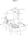
- the electronic means could also allow the inclusion of a camera system on the food dispenser ( figure 3 ) to interact with the animal remotely.
- the present invention provides a food dispenser 10, "dispenser” 10 hereinafter, for dispensing food in suitable conditions to be consumed by living beings, especially for feeding pets, dogs or the like, wherein the dosing device 1, as previously described, is installable or attachable to a main frame 2 of the food dispenser 10.
- the dispenser 10 comprises a main frame 2 to which the tank 3 is engageable, particularly the tank 3 can be attached to a distribution frame 20 of the dispenser 10.
- the dispenser 10 may also comprise driving means configured to drive the removing means 4 and the dosing plate 6 of the device 1.
- the motor 11 could be mounted on the distribution frame 20 to drive the dosing plate 6. Since the dosing plate 6 is a disc plate with gear teeth 63 at its periphery, the motor 11 has at its output a driving gear (not shown) to drive said dosing plate 6.
- Other type of mechanisms could be used within the scope of the invention, like a gear worm mechanism, a pulley and sprocket, wherein the driving element, like the motor 11 is provided in the dispenser 10, while the driven elements, like the dosing plate 6 or the agitator 40, are provided in the device 1, etc.
- a water tank 13 for storing water or liquid is engageable to a tank frame 12 which is, at the same time, engageable to the main frame 2, wherein the nozzle 15 of the device 1 is in fluid communication with the water tank 13.
- the watering means also comprise a water bowl 14, configured to receive a quantity of water to be drunk by pets or other living beings.
- the water bowl 14 could be supplied with water from the water tank 13, being the dispenser 10 provided with suitable means, like a pump and its accessories, to control and dispense the water from the water tank 13 to the different parts where it is required.
- this suitable means like a water pump or similar and its accessories, to control and dispense the water, could be provided in the device as a part of the watering means.
- the moisture extraction means could be mounted on the main frame 2 of the dispenser 10. That is to say, the blower or fan (not shown) could be attachable to the distribution frame 20 and configured to blow fresh air into said distribution frame 20 in order to dry the drops of water or the general moisture at the outlet plate 7, after the food has been watered.
- the distribution frame 20 comprises a first plurality of through holes 21 and a second plurality of through holes 22, wherein said pluralities of through holes 21 22 are configured to allow the air to flow through the distribution frame 20 to evacuate or dry the undesired moisture, drops or water steam remaining after the food has been watered and delivered.
- the elongated plates 31 and the outlet plate 7 of the device 1 could also be a part of the main frame 20 of the dispenser 10 instead of being part of the tank 3, both elements configured to perform the same functions previously described.
- the plurality of ribs 73 could also be part of the main frame 20 of the dispenser 10 instead of being part of the dosing device 1, for the same purposes previously described.
- the aeration could be held through the holes 21 22 and the apertures 31A of the elongated plates 31 to the enclosed area formed by the plurality of ribs 73 of the outlet plate 7 in order to eliminate the undesired humidity or to dry the drops on the outlet plate 7 after watering the food
- the dispenser 10 further comprises a bowl 9 which is engageable to a bowl carrier 90 inside the main frame 2, said bowl carrier 90 is movable and it is configured to move the bowl 9 from a filling position, below the outlet plate 7, where said bowl 9 is filled with food coming from the outlet plate 7 to an external feeding position where living beings can eat from said bowl 9.
- the elongated plates 31 provide an enclosing over the bowl 9 to direct the whole sprayed water to food, preventing the water from going to other parts of the device.
- the dispenser 10 comprises electronic or processing control means (not shown), like a CPU or similar, in order to control the general functioning of said dispenser 10.
- This electronic or processing control means can be linked with the electronic control means of the device 1 or can replace or superimpose over the electronic control means.
- the electronic or processing control means could receive a signal from a food level sensor (not shown) to know the quantity of food stored in the tank 3 and also could send a drive signal to the driving means to drive the removing means 4 and/or the dosing plate 6 to dispense the food in the bowl 9, as well as controlling the watering means (the activation of the nozzle 15), to water the food in the bowl 9, or the heating means to heat the food, or to move the bowl carrier 90 inside or outside to dispense the prepared food, or to activate the blower of the moisture extraction means.
- a food level sensor not shown
- the electronic or processing control means could receive a signal from a food level sensor (not shown) to know the quantity of food stored in the tank 3 and also could send a drive signal to the driving means to drive the removing means 4 and/or the dosing plate 6 to dispense the food in the bowl 9, as well as controlling the watering means (the activation of the nozzle 15), to water the food in the bowl 9, or the heating means to heat the food, or to move
- the dosing device 1 could also include an RFID tag and the food dispenser 10 could include an RFID reader, so that when the dosing device 1 is incorporated into the dispenser 10, some predefined cooking parameters could be set (e.g.: food-water ratio, watering and rehydration time, heating temperature) adapted to the specific food recipe contained in the dosing device 1. This would allow the food dispenser 10 to dose, prepare and dispense food in the perfect consuming conditions.
- some predefined cooking parameters e.g.: food-water ratio, watering and rehydration time, heating temperature
Landscapes
- Life Sciences & Earth Sciences (AREA)
- Environmental Sciences (AREA)
- Physics & Mathematics (AREA)
- Fluid Mechanics (AREA)
- General Physics & Mathematics (AREA)
- Birds (AREA)
- Animal Husbandry (AREA)
- Biodiversity & Conservation Biology (AREA)
- Food-Manufacturing Devices (AREA)
- Feeding And Watering For Cattle Raising And Animal Husbandry (AREA)
- Frying-Pans Or Fryers (AREA)
Claims (14)
- Dosiervorrichtung (1) für eine Lebensmittelausgabevorrichtung, die Folgendes umfasst:- einen Tank (3), der dazu ausgelegt ist, ein Lebensmittel aufzunehmen und zu speichern;- eine Dosierplatte (6), die mit Bezug auf den Tank (3), der mindestens ein Fach (60) umfasst, das dazu ausgelegt ist, das Lebensmittel aufzunehmen und zu messen, bewegbar ist; und- eine Auslassplatte (7), die mindestens ein Auslassloch (70) umfasst, wobei die Auslassplatte (7) dazu ausgelegt ist, das Fach (60) zu sperren und zu entsperren, und wobei das Fach (60) dazu ausgelegt ist, eine Fluidkommunikation mit dem Auslassloch (70) herzustellen;dadurch gekennzeichnet, dass sie Folgendes umfasst:- mindestens eine Düse (15), die dazu ausgelegt ist, einen Wassersprühkegel (16) über das Lebensmittel zu injiziieren, nachdem es von der Dosiervorrichtung (1) in einer Schüssel oder einer Wanne dosiert wurde, wobei die Düse (15), die in der Dosiervorrichtung (1) bereitgestelltist, dazu ausgelegt ist, gemäß der dlogenden Formel H=
 H: Höhe der Düse (15) über dem Lebensmittel in MillimeterR: Radius der Schüssel oder der Wanne, wo das Lebensmittel dosiert wird, in Millimetertan: Tangensh: mathematische Konstante, im Bereich von 30-90, vorzugsweise im Bereich von 60-68, insbesondere 64 undk: mathematische Konstante, im Bereich von 0-20, vorzugsweise im Bereich von 9-12, insbesondere 10,6.
 - Vorrichtung nach Anspruch 1, die ferner eine Einlassplatte (5) umfasst, die mindestens ein Einlassloch (50) umfasst; wobei die Dosierplatte (6) dazu ausgelegt ist, das Einlassloch (50) zu sperren oder zu entsperren, und wobei das Einlassloch (50) dazu ausgelegt ist, eine Fluidkommunikation mit dem Fach (60) herzustellen.
- Vorrichtung nach Anspruch 2, die ferner eine Zwischenplatte (8) neben der Einlassplatte (5) umfasst, wobei die Zwischenplatte (8) mindestens ein Zwischenloch (80) umfasst, das dazu ausgelegt ist, auf das Einlassloch (50) ausgerichtet zu werden und eine Fluidkommunikation mit dem Fach (60) der Dosierplatte (6) herzustellen.
- Vorrichtung der Ansprüche 1 bis 3, wobei die Einlassplatte (5) mindestens ein inneres radiales Einlassloch (51) und mindestens ein äußeres radiales Einlassloch (52) umfasst, die Dosierplatte (6) mindestens ein inneres radiales Fach (61) und ein äußeres radiales Fach (62) umfasst, die Auslassplatte (7) mindestens ein inneres radiales Auslassloch (71) und ein äußeres radiales Auslassloch (72) umfasst und die Zwischenplatte (8) mindestens ein inneres radiales Zwischenloch (81) und mindestens ein äußeres radiales Zwischenloch (82) umfasst, wobeidas innere radiale Einlassloch (51) und das äußere radiale Auslassloch (52) dazu ausgelegt sind, von der Dosierplatte (6) gesperrt oder entsperrt zu werden, und das innere radiale Fach (61) und das äußere radiale Fach (62) dazu ausgelegt sind, eine Fluidkommunikation mit dem inneren Einlassloch (51) und mit dem äußeren Einlassloch (52) herzustellen;das innere Auslassloch (71) und das äußere Auslassloch (72) dazu ausgelegt sind, jeweils mindestens teilweise auf das innere Fach (61) und das äußere Fach (62) ausgerichtet zu sein und eine Fluidkommunikation mit diesen herzustellen, wobei das innere radiale Fach (61) und das äußere radiale Fach (62) dazu ausgelegt sind, durch die Bewegung der Dosierplatte (6) gegen die Auslassplatte (7) gesperrt oder entsperrt zu werden; unddas innere Zwischenloch (81) und das äußere Zwischenloch (82) dazu ausgelegt sind, jeweils auf das innere Einlassloch (51) und auf das äußere Einlassloch (52) ausgerichtet zu sein.
- Vorrichtung nach einem der vorhergehenden Ansprüche, die ferner Feuchtigkeitsextraktionsmittel umfasst, die dazu ausgelegt sind, die Feuchtigkeit in der Vorrichtung und/oder im Lebensmittel zu verringern oder zu beseitigen.
- Vorrichtung nach einem der vorhergehenden Ansprüche, die ferner Bewässerungsmittel umfasst, die dazu ausgelegt sind, das im Tank (3) befindliche Lebensmittel und/oder das einmal dosierte Lebensmittel zu bewässern.
- Vorrichtung nach einem der vorhergehenden Ansprüche, das ferner Entfernungsmittel (4) umfasst, die dazu ausgelegt sind, das in den Tank (3) aufgenommene Lebensmittel vorwärtszutreiben und zu entfernen.
- Vorrichtung nach einem der vorhergehenden Ansprüche, die ferner Antriebsmittel umfasst, die dazu ausgelegt sind, die Dosierplatte (6) anzutreiben und/oder die Entfernungsmittel (4) anzutreiben.
- Vorrichtung nach den Ansprüchen 7 oder 8, wobei die Entfernungsmittel (4) ein Rührwerk (40) umfassen, das dazu ausgelegt ist, das in den Tank (3) aufgenommene Lebensmittel vorwärtszutreiben und zu entfernen, wobei das Rührwerk (40) um eine Drehachse (41) drehbar ist, die mit der Dosierplatte (6) oder mit den Antriebsmitteln wirkverbunden ist, und Blätter (42) (43) (44) umfasst, wobei mindestens eines der Blätter (42) (43) (44) mit Bezug auf die Axialrichtung der Drehachse (41) gegenüber den anderen in einer anderen Höhe angeordnet ist.
- Vorrichtung nach einem der vorhergehenden Ansprüche, die einen Plattenrahmen (5A) umfasst, der in den Tank (3) einrückbar ist, wobei die Einlassplatte (5) als Teil des Plattenrahmens (5A) bereitgestellt ist und wobei die Dosierplatte (6) in den Plattenrahmen (5A) einrückbar ist.
- Vorrichtung nach einem der vorhergehenden Ansprüche, die ferner Heizmittel umfasst, die dazu ausgelegt sind, das Wasser zu erhitzen, bevor die Bewässerung stattfindet, und/oder das Lebensmittel vor, während und/oder nach der Dosierung zu erhitzen.
- Vorrichtung nach einem der vorhergehenden Ansprüche, wobei die Auslassplatte (7) mit einer Vielzahl von Rippen (73) wirkverbunden ist, die dazu ausgelegt sind, die Belüftung der Auslassplatte (7) zu erlauben, wobei die Vielzahl von Rippen (73) in der Auslassplatte (7) oder im Plattenrahmen (5A) bereitgestellt ist.
- Vorrichtung nach einem der Ansprüche 6 bis 12, die ferner eine längliche Platte (31) umfasst, die sich von der Auslassplatte (7) erstreckt und dazu ausgelegt ist, eine weitere Bewässerung nach der Dosierung des Lebensmittels zu vermeiden, wobei die längliche Platte (31) im Tank (3) oder im Plattenrahmen (5A) bereitgestellt oder mit denselben wirkverbunden ist.
- Lebensmittelausgabevorrichtung (10) zum automatischen Ausgeben von Lebensmittel, die die Dosiervorrichtung (1) nach einem der Ansprüche 1 bis 13 umfasst.
Priority Applications (4)
| Application Number | Priority Date | Filing Date | Title |
|---|---|---|---|
| EP22382032.5A EP4215882B1 (de) | 2022-01-19 | 2022-01-19 | Dosiervorrichtung für einen lebensmittelspender |
| ES22382032T ES3032518T3 (en) | 2022-01-19 | 2022-01-19 | Dosing device for a food dispenser |
| PCT/EP2023/051203 WO2023139153A1 (en) | 2022-01-19 | 2023-01-19 | Dosing device for a food dispenser |
| US18/729,502 US20250160296A1 (en) | 2022-01-19 | 2023-01-19 | Dosing device for a food dispenser |
Applications Claiming Priority (1)
| Application Number | Priority Date | Filing Date | Title |
|---|---|---|---|
| EP22382032.5A EP4215882B1 (de) | 2022-01-19 | 2022-01-19 | Dosiervorrichtung für einen lebensmittelspender |
Publications (3)
| Publication Number | Publication Date |
|---|---|
| EP4215882A1 EP4215882A1 (de) | 2023-07-26 |
| EP4215882B1 true EP4215882B1 (de) | 2025-05-14 |
| EP4215882C0 EP4215882C0 (de) | 2025-05-14 |
Family
ID=80222550
Family Applications (1)
| Application Number | Title | Priority Date | Filing Date |
|---|---|---|---|
| EP22382032.5A Active EP4215882B1 (de) | 2022-01-19 | 2022-01-19 | Dosiervorrichtung für einen lebensmittelspender |
Country Status (4)
| Country | Link |
|---|---|
| US (1) | US20250160296A1 (de) |
| EP (1) | EP4215882B1 (de) |
| ES (1) | ES3032518T3 (de) |
| WO (1) | WO2023139153A1 (de) |
Family Cites Families (37)
| Publication number | Priority date | Publication date | Assignee | Title |
|---|---|---|---|---|
| US2584781A (en) * | 1946-02-11 | 1952-02-05 | Beatty Brook | Bracket and holder for inverted container of bulk material with means for dispensing measured quantities of said material |
| US2944707A (en) * | 1957-08-05 | 1960-07-12 | William J Steinmetz | Dispensing device |
| US3386624A (en) * | 1966-09-21 | 1968-06-04 | Carlo E. Valente | Dispensing device for powdered material |
| US3920224A (en) * | 1972-07-27 | 1975-11-18 | Fassauer Ind Inc | Particulate material feeder |
| US3989166A (en) * | 1975-08-04 | 1976-11-02 | Lawrence Peska Associates, Inc. | Apparatus for metering and dispensing |
| US4032050A (en) * | 1976-02-19 | 1977-06-28 | Funk Richard J | Measuring closure for containers |
| US4322017A (en) * | 1979-11-29 | 1982-03-30 | Lowdermilk Charles H | Dispensing device |
| US4572376A (en) * | 1982-09-16 | 1986-02-25 | Wrennall Richard K | Dial pill box |
| ZW15085A1 (en) * | 1984-09-17 | 1986-01-29 | Pioneer Seed Co Pty Ltd | Dispenser for fluids |
| US4832235A (en) * | 1987-05-11 | 1989-05-23 | Palmer Warren C | Self-measuring condiment cap |
| US5307736A (en) * | 1992-11-16 | 1994-05-03 | Sorensen Richard H | Food cooking |
| JP3487647B2 (ja) * | 1993-11-11 | 2004-01-19 | 株式会社エヌテック | 粉粒体の定量排出器 |
| US5529221A (en) * | 1994-05-16 | 1996-06-25 | Roy; Harold Van | Metered serving dispenser of granular materials |
| DE19938637C2 (de) * | 1999-07-05 | 2003-11-13 | Martin Foerster | Verfahren zum automatischen Kalibrieren einer Vorrichtung zum Versorgen von Haustieren |
| US6550640B2 (en) * | 2001-03-12 | 2003-04-22 | William G. Smith | Method and apparatus for controllably dispensing powders and liquids |
| US8636173B2 (en) * | 2001-06-01 | 2014-01-28 | Cosmetic Technologies, L.L.C. | Point-of-sale body powder dispensing system |
| US7950550B2 (en) * | 2004-05-06 | 2011-05-31 | Diversey, Inc. | Metering and dispensing closure |
| US20050279766A1 (en) * | 2004-06-04 | 2005-12-22 | Wiegner Thomas F | Dispensing system and method of use |
| KR100900984B1 (ko) * | 2007-08-30 | 2009-06-04 | 장수진 | 분유 및 분말 디스펜서 |
| DE102007045905A1 (de) * | 2007-09-26 | 2009-04-09 | Amazonen-Werke H. Dreyer Gmbh & Co. Kg | Dosiervorrichtung |
| TW200930288A (en) * | 2008-01-03 | 2009-07-16 | Claridy Solutions Inc | Animal feeding device |
| US8047408B2 (en) * | 2008-07-17 | 2011-11-01 | Prince Castle LLC | Dispenser for granules and powders |
| CN102215725B (zh) * | 2008-09-17 | 2016-05-04 | 皇家戴维艾格伯茨有限公司 | 用于制备咖啡饮料的系统以及相关方法 |
| GB0819220D0 (en) | 2008-10-21 | 2008-11-26 | Laliberte Jean Charles | Automatic food dispenser |
| ES2435434T3 (es) * | 2008-12-03 | 2013-12-19 | Koninklijke Douwe Egberts B.V. | Sistema, envase, aparato y procedimiento para dosificar granos de café |
| US9295271B2 (en) * | 2011-10-28 | 2016-03-29 | Richard J. Rothamel | Heat activated warm pet foods |
| WO2013078379A2 (en) * | 2011-11-23 | 2013-05-30 | Comaker Llc | System and process for creating medium viscosity food or personal care products by rapid rehydration |
| ES2577383T3 (es) * | 2012-05-11 | 2016-07-14 | Novartis Ag | Dispositivo dispensador |
| CN104054592A (zh) * | 2014-07-14 | 2014-09-24 | 南京通孚轻纺有限公司 | 一种自动宠物喂食器 |
| US20160109273A1 (en) * | 2014-10-20 | 2016-04-21 | Mark LaFosse | Powder Dosing System |
| FR3045274B1 (fr) * | 2015-12-16 | 2017-12-29 | Seb Sa | Appareil de preparation d'aliments pour animaux |
| AU2017270023A1 (en) * | 2016-05-25 | 2018-11-22 | Ew Nutrition Gmbh | Device, liquid reservoir, system and use of a liquid reservoir for the currentless sprinkling of animal feed |
| US10798916B2 (en) * | 2016-06-14 | 2020-10-13 | The Animal Docs LLC | Apparatus and method for dispensing food, medication and supplements for animals |
| US11363799B2 (en) * | 2017-11-06 | 2022-06-21 | The Full Life Company | Fresh-serve pet food system |
| ES1212563Y (es) * | 2018-05-02 | 2018-09-07 | Martori Albert Icart | Maquina y capsula para rehidratar alimentos deshidratados |
| US11006614B2 (en) * | 2018-09-29 | 2021-05-18 | Dogness Group LLC | Smart pet feeder |
| US11553691B2 (en) * | 2020-01-07 | 2023-01-17 | Dongguan Jiasheng Enterprise Co., Ltd | Anti-stuck pet feeder |
-
2022
- 2022-01-19 EP EP22382032.5A patent/EP4215882B1/de active Active
- 2022-01-19 ES ES22382032T patent/ES3032518T3/es active Active
-
2023
- 2023-01-19 US US18/729,502 patent/US20250160296A1/en active Pending
- 2023-01-19 WO PCT/EP2023/051203 patent/WO2023139153A1/en not_active Ceased
Also Published As
| Publication number | Publication date |
|---|---|
| ES3032518T3 (en) | 2025-07-21 |
| WO2023139153A1 (en) | 2023-07-27 |
| EP4215882A1 (de) | 2023-07-26 |
| EP4215882C0 (de) | 2025-05-14 |
| US20250160296A1 (en) | 2025-05-22 |
Similar Documents
| Publication | Publication Date | Title |
|---|---|---|
| EP2083660B1 (de) | Vorrichtung zur zubereitung von säuglingsmilch aus einem instant-pulver | |
| CN104582466B (zh) | 具有改进的液体涂敷的种子处理装置 | |
| EA007368B1 (ru) | Устройство, способ и система для нанесения веществ на фураж, зерно или растительную массу перед или после уборки | |
| MX2015000299A (es) | Aparato de tratamiento de semillas con funcionalidad dosificadora. | |
| EP3389368B1 (de) | Gerät zur vorbereitung von haustierfutter | |
| US5551374A (en) | Automated nipple livestock feeder and method of operation | |
| US11805764B2 (en) | System and method for delivering nutrients to recently hatched chicks | |
| US5385306A (en) | Fertilizer spreader attachable to a lawn mower | |
| PL184194B1 (pl) | Urządzenie do karmienia zwierząt domowych, zwłaszcza świń | |
| KR20160148221A (ko) | 가축용 분유 자동혼합기 | |
| US8359888B2 (en) | Dispensing system for powdered treating agent for use in a washing machine, and washing machine | |
| US3425398A (en) | Apparatus for dispensing artificial food to young animals | |
| EP4215882A1 (de) | Dosiervorrichtung für einen lebensmittelspender | |
| EP1713322B1 (de) | Fütterunsvorrichtung, insbesondere für aquarien | |
| EP3017691B1 (de) | Vorrichtung zum füttern von ferkeln mit frischem und sofort zubereitetem flüssigfutter | |
| CN109152406B (zh) | 动物食物制备设备 | |
| GB2259652A (en) | Animal feeding system | |
| WO2006031924A2 (en) | Automated dispenser | |
| BR112020019614B1 (pt) | Aparelho para fornecer produtos digeríveis para aves recémnascidas |
Legal Events
| Date | Code | Title | Description |
|---|---|---|---|
| PUAI | Public reference made under article 153(3) epc to a published international application that has entered the european phase |
Free format text: ORIGINAL CODE: 0009012 |
|
| STAA | Information on the status of an ep patent application or granted ep patent |
Free format text: STATUS: THE APPLICATION HAS BEEN PUBLISHED |
|
| AK | Designated contracting states |
Kind code of ref document: A1 Designated state(s): AL AT BE BG CH CY CZ DE DK EE ES FI FR GB GR HR HU IE IS IT LI LT LU LV MC MK MT NL NO PL PT RO RS SE SI SK SM TR |
|
| STAA | Information on the status of an ep patent application or granted ep patent |
Free format text: STATUS: REQUEST FOR EXAMINATION WAS MADE |
|
| 17P | Request for examination filed |
Effective date: 20240125 |
|
| RBV | Designated contracting states (corrected) |
Designated state(s): AL AT BE BG CH CY CZ DE DK EE ES FI FR GB GR HR HU IE IS IT LI LT LU LV MC MK MT NL NO PL PT RO RS SE SI SK SM TR |
|
| REG | Reference to a national code |
Ref country code: DE Ref legal event code: R079 Free format text: PREVIOUS MAIN CLASS: G01F0011240000 Ipc: A23F0005000000 Ref country code: DE Ref legal event code: R079 Ref document number: 602022014628 Country of ref document: DE Free format text: PREVIOUS MAIN CLASS: G01F0011240000 Ipc: A23F0005000000 |
|
| GRAP | Despatch of communication of intention to grant a patent |
Free format text: ORIGINAL CODE: EPIDOSNIGR1 |
|
| STAA | Information on the status of an ep patent application or granted ep patent |
Free format text: STATUS: GRANT OF PATENT IS INTENDED |
|
| RIC1 | Information provided on ipc code assigned before grant |
Ipc: G01F 11/24 20060101ALI20250123BHEP Ipc: A23F 5/00 20060101AFI20250123BHEP |
|
| INTG | Intention to grant announced |
Effective date: 20250207 |
|
| GRAS | Grant fee paid |
Free format text: ORIGINAL CODE: EPIDOSNIGR3 |
|
| GRAA | (expected) grant |
Free format text: ORIGINAL CODE: 0009210 |
|
| STAA | Information on the status of an ep patent application or granted ep patent |
Free format text: STATUS: THE PATENT HAS BEEN GRANTED |
|
| AK | Designated contracting states |
Kind code of ref document: B1 Designated state(s): AL AT BE BG CH CY CZ DE DK EE ES FI FR GB GR HR HU IE IS IT LI LT LU LV MC MK MT NL NO PL PT RO RS SE SI SK SM TR |
|
| REG | Reference to a national code |
Ref country code: GB Ref legal event code: FG4D |
|
| REG | Reference to a national code |
Ref country code: CH Ref legal event code: EP |
|
| REG | Reference to a national code |
Ref country code: IE Ref legal event code: FG4D |
|
| REG | Reference to a national code |
Ref country code: DE Ref legal event code: R096 Ref document number: 602022014628 Country of ref document: DE |
|
| U01 | Request for unitary effect filed |
Effective date: 20250604 |
|
| U07 | Unitary effect registered |
Designated state(s): AT BE BG DE DK EE FI FR IT LT LU LV MT NL PT RO SE SI Effective date: 20250612 |
|
| REG | Reference to a national code |
Ref country code: ES Ref legal event code: FG2A Ref document number: 3032518 Country of ref document: ES Kind code of ref document: T3 Effective date: 20250721 |
|
| PG25 | Lapsed in a contracting state [announced via postgrant information from national office to epo] |
Ref country code: NO Free format text: LAPSE BECAUSE OF FAILURE TO SUBMIT A TRANSLATION OF THE DESCRIPTION OR TO PAY THE FEE WITHIN THE PRESCRIBED TIME-LIMIT Effective date: 20250814 Ref country code: GR Free format text: LAPSE BECAUSE OF FAILURE TO SUBMIT A TRANSLATION OF THE DESCRIPTION OR TO PAY THE FEE WITHIN THE PRESCRIBED TIME-LIMIT Effective date: 20250815 |
|
| PG25 | Lapsed in a contracting state [announced via postgrant information from national office to epo] |
Ref country code: PL Free format text: LAPSE BECAUSE OF FAILURE TO SUBMIT A TRANSLATION OF THE DESCRIPTION OR TO PAY THE FEE WITHIN THE PRESCRIBED TIME-LIMIT Effective date: 20250514 |
|
| PG25 | Lapsed in a contracting state [announced via postgrant information from national office to epo] |
Ref country code: HR Free format text: LAPSE BECAUSE OF FAILURE TO SUBMIT A TRANSLATION OF THE DESCRIPTION OR TO PAY THE FEE WITHIN THE PRESCRIBED TIME-LIMIT Effective date: 20250514 |
|
| PG25 | Lapsed in a contracting state [announced via postgrant information from national office to epo] |
Ref country code: RS Free format text: LAPSE BECAUSE OF FAILURE TO SUBMIT A TRANSLATION OF THE DESCRIPTION OR TO PAY THE FEE WITHIN THE PRESCRIBED TIME-LIMIT Effective date: 20250814 |
|
| PG25 | Lapsed in a contracting state [announced via postgrant information from national office to epo] |
Ref country code: IS Free format text: LAPSE BECAUSE OF FAILURE TO SUBMIT A TRANSLATION OF THE DESCRIPTION OR TO PAY THE FEE WITHIN THE PRESCRIBED TIME-LIMIT Effective date: 20250914 |
|
| PG25 | Lapsed in a contracting state [announced via postgrant information from national office to epo] |
Ref country code: SM Free format text: LAPSE BECAUSE OF FAILURE TO SUBMIT A TRANSLATION OF THE DESCRIPTION OR TO PAY THE FEE WITHIN THE PRESCRIBED TIME-LIMIT Effective date: 20250514 |
|
| PG25 | Lapsed in a contracting state [announced via postgrant information from national office to epo] |
Ref country code: CZ Free format text: LAPSE BECAUSE OF FAILURE TO SUBMIT A TRANSLATION OF THE DESCRIPTION OR TO PAY THE FEE WITHIN THE PRESCRIBED TIME-LIMIT Effective date: 20250514 |
|
| PG25 | Lapsed in a contracting state [announced via postgrant information from national office to epo] |
Ref country code: SK Free format text: LAPSE BECAUSE OF FAILURE TO SUBMIT A TRANSLATION OF THE DESCRIPTION OR TO PAY THE FEE WITHIN THE PRESCRIBED TIME-LIMIT Effective date: 20250514 |
|
| PLBE | No opposition filed within time limit |
Free format text: ORIGINAL CODE: 0009261 |
|
| STAA | Information on the status of an ep patent application or granted ep patent |
Free format text: STATUS: NO OPPOSITION FILED WITHIN TIME LIMIT |
|
| REG | Reference to a national code |
Ref country code: CH Ref legal event code: L10 Free format text: ST27 STATUS EVENT CODE: U-0-0-L10-L00 (AS PROVIDED BY THE NATIONAL OFFICE) Effective date: 20260325 |
|
| 26N | No opposition filed |
Effective date: 20260217 |