EP4215934A1 - Détection d'objets fantômas dans les véhicules - Google Patents
Détection d'objets fantômas dans les véhicules Download PDFInfo
- Publication number
- EP4215934A1 EP4215934A1 EP22199449.4A EP22199449A EP4215934A1 EP 4215934 A1 EP4215934 A1 EP 4215934A1 EP 22199449 A EP22199449 A EP 22199449A EP 4215934 A1 EP4215934 A1 EP 4215934A1
- Authority
- EP
- European Patent Office
- Prior art keywords
- objects
- velocity
- ghost
- moving
- reflection
- Prior art date
- Legal status (The legal status is an assumption and is not a legal conclusion. Google has not performed a legal analysis and makes no representation as to the accuracy of the status listed.)
- Granted
Links
Images






Classifications
-
- G—PHYSICS
- G01—MEASURING; TESTING
- G01S—RADIO DIRECTION-FINDING; RADIO NAVIGATION; DETERMINING DISTANCE OR VELOCITY BY USE OF RADIO WAVES; LOCATING OR PRESENCE-DETECTING BY USE OF THE REFLECTION OR RERADIATION OF RADIO WAVES; ANALOGOUS ARRANGEMENTS USING OTHER WAVES
- G01S17/00—Systems using the reflection or reradiation of electromagnetic waves other than radio waves, e.g. lidar systems
- G01S17/88—Lidar systems specially adapted for specific applications
- G01S17/93—Lidar systems specially adapted for specific applications for anti-collision purposes
- G01S17/931—Lidar systems specially adapted for specific applications for anti-collision purposes of land vehicles
-
- G—PHYSICS
- G01—MEASURING; TESTING
- G01S—RADIO DIRECTION-FINDING; RADIO NAVIGATION; DETERMINING DISTANCE OR VELOCITY BY USE OF RADIO WAVES; LOCATING OR PRESENCE-DETECTING BY USE OF THE REFLECTION OR RERADIATION OF RADIO WAVES; ANALOGOUS ARRANGEMENTS USING OTHER WAVES
- G01S7/00—Details of systems according to groups G01S13/00, G01S15/00, G01S17/00
- G01S7/02—Details of systems according to groups G01S13/00, G01S15/00, G01S17/00 of systems according to group G01S13/00
- G01S7/36—Means for anti-jamming, e.g. ECCM, i.e. electronic counter-counter measures
-
- G—PHYSICS
- G01—MEASURING; TESTING
- G01S—RADIO DIRECTION-FINDING; RADIO NAVIGATION; DETERMINING DISTANCE OR VELOCITY BY USE OF RADIO WAVES; LOCATING OR PRESENCE-DETECTING BY USE OF THE REFLECTION OR RERADIATION OF RADIO WAVES; ANALOGOUS ARRANGEMENTS USING OTHER WAVES
- G01S13/00—Systems using the reflection or reradiation of radio waves, e.g. radar systems; Analogous systems using reflection or reradiation of waves whose nature or wavelength is irrelevant or unspecified
- G01S13/02—Systems using reflection of radio waves, e.g. primary radar systems; Analogous systems
- G01S13/06—Systems determining position data of a target
-
- G—PHYSICS
- G01—MEASURING; TESTING
- G01S—RADIO DIRECTION-FINDING; RADIO NAVIGATION; DETERMINING DISTANCE OR VELOCITY BY USE OF RADIO WAVES; LOCATING OR PRESENCE-DETECTING BY USE OF THE REFLECTION OR RERADIATION OF RADIO WAVES; ANALOGOUS ARRANGEMENTS USING OTHER WAVES
- G01S13/00—Systems using the reflection or reradiation of radio waves, e.g. radar systems; Analogous systems using reflection or reradiation of waves whose nature or wavelength is irrelevant or unspecified
- G01S13/02—Systems using reflection of radio waves, e.g. primary radar systems; Analogous systems
- G01S13/06—Systems determining position data of a target
- G01S13/42—Simultaneous measurement of distance and other co-ordinates
-
- G—PHYSICS
- G01—MEASURING; TESTING
- G01S—RADIO DIRECTION-FINDING; RADIO NAVIGATION; DETERMINING DISTANCE OR VELOCITY BY USE OF RADIO WAVES; LOCATING OR PRESENCE-DETECTING BY USE OF THE REFLECTION OR RERADIATION OF RADIO WAVES; ANALOGOUS ARRANGEMENTS USING OTHER WAVES
- G01S13/00—Systems using the reflection or reradiation of radio waves, e.g. radar systems; Analogous systems using reflection or reradiation of waves whose nature or wavelength is irrelevant or unspecified
- G01S13/02—Systems using reflection of radio waves, e.g. primary radar systems; Analogous systems
- G01S13/50—Systems of measurement based on relative movement of target
- G01S13/58—Velocity or trajectory determination systems; Sense-of-movement determination systems
- G01S13/581—Velocity or trajectory determination systems; Sense-of-movement determination systems using transmission of interrupted pulse modulated waves and based upon the Doppler effect resulting from movement of targets
- G01S13/582—Velocity or trajectory determination systems; Sense-of-movement determination systems using transmission of interrupted pulse modulated waves and based upon the Doppler effect resulting from movement of targets adapted for simultaneous range and velocity measurements
-
- G—PHYSICS
- G01—MEASURING; TESTING
- G01S—RADIO DIRECTION-FINDING; RADIO NAVIGATION; DETERMINING DISTANCE OR VELOCITY BY USE OF RADIO WAVES; LOCATING OR PRESENCE-DETECTING BY USE OF THE REFLECTION OR RERADIATION OF RADIO WAVES; ANALOGOUS ARRANGEMENTS USING OTHER WAVES
- G01S13/00—Systems using the reflection or reradiation of radio waves, e.g. radar systems; Analogous systems using reflection or reradiation of waves whose nature or wavelength is irrelevant or unspecified
- G01S13/02—Systems using reflection of radio waves, e.g. primary radar systems; Analogous systems
- G01S13/50—Systems of measurement based on relative movement of target
- G01S13/58—Velocity or trajectory determination systems; Sense-of-movement determination systems
- G01S13/583—Velocity or trajectory determination systems; Sense-of-movement determination systems using transmission of continuous unmodulated waves, amplitude-, frequency-, or phase-modulated waves and based upon the Doppler effect resulting from movement of targets
- G01S13/584—Velocity or trajectory determination systems; Sense-of-movement determination systems using transmission of continuous unmodulated waves, amplitude-, frequency-, or phase-modulated waves and based upon the Doppler effect resulting from movement of targets adapted for simultaneous range and velocity measurements
-
- G—PHYSICS
- G01—MEASURING; TESTING
- G01S—RADIO DIRECTION-FINDING; RADIO NAVIGATION; DETERMINING DISTANCE OR VELOCITY BY USE OF RADIO WAVES; LOCATING OR PRESENCE-DETECTING BY USE OF THE REFLECTION OR RERADIATION OF RADIO WAVES; ANALOGOUS ARRANGEMENTS USING OTHER WAVES
- G01S13/00—Systems using the reflection or reradiation of radio waves, e.g. radar systems; Analogous systems using reflection or reradiation of waves whose nature or wavelength is irrelevant or unspecified
- G01S13/66—Radar-tracking systems; Analogous systems
- G01S13/72—Radar-tracking systems; Analogous systems for two-dimensional [2D] tracking, e.g. combination of angle and range tracking, track-while-scan radar
-
- G—PHYSICS
- G01—MEASURING; TESTING
- G01S—RADIO DIRECTION-FINDING; RADIO NAVIGATION; DETERMINING DISTANCE OR VELOCITY BY USE OF RADIO WAVES; LOCATING OR PRESENCE-DETECTING BY USE OF THE REFLECTION OR RERADIATION OF RADIO WAVES; ANALOGOUS ARRANGEMENTS USING OTHER WAVES
- G01S13/00—Systems using the reflection or reradiation of radio waves, e.g. radar systems; Analogous systems using reflection or reradiation of waves whose nature or wavelength is irrelevant or unspecified
- G01S13/88—Radar or analogous systems specially adapted for specific applications
- G01S13/93—Radar or analogous systems specially adapted for specific applications for anti-collision purposes
- G01S13/931—Radar or analogous systems specially adapted for specific applications for anti-collision purposes of land vehicles
-
- G—PHYSICS
- G01—MEASURING; TESTING
- G01S—RADIO DIRECTION-FINDING; RADIO NAVIGATION; DETERMINING DISTANCE OR VELOCITY BY USE OF RADIO WAVES; LOCATING OR PRESENCE-DETECTING BY USE OF THE REFLECTION OR RERADIATION OF RADIO WAVES; ANALOGOUS ARRANGEMENTS USING OTHER WAVES
- G01S17/00—Systems using the reflection or reradiation of electromagnetic waves other than radio waves, e.g. lidar systems
- G01S17/02—Systems using the reflection of electromagnetic waves other than radio waves
- G01S17/06—Systems determining position data of a target
- G01S17/42—Simultaneous measurement of distance and other co-ordinates
-
- G—PHYSICS
- G01—MEASURING; TESTING
- G01S—RADIO DIRECTION-FINDING; RADIO NAVIGATION; DETERMINING DISTANCE OR VELOCITY BY USE OF RADIO WAVES; LOCATING OR PRESENCE-DETECTING BY USE OF THE REFLECTION OR RERADIATION OF RADIO WAVES; ANALOGOUS ARRANGEMENTS USING OTHER WAVES
- G01S7/00—Details of systems according to groups G01S13/00, G01S15/00, G01S17/00
- G01S7/02—Details of systems according to groups G01S13/00, G01S15/00, G01S17/00 of systems according to group G01S13/00
- G01S7/28—Details of pulse systems
- G01S7/285—Receivers
- G01S7/292—Extracting wanted echo-signals
-
- G—PHYSICS
- G01—MEASURING; TESTING
- G01S—RADIO DIRECTION-FINDING; RADIO NAVIGATION; DETERMINING DISTANCE OR VELOCITY BY USE OF RADIO WAVES; LOCATING OR PRESENCE-DETECTING BY USE OF THE REFLECTION OR RERADIATION OF RADIO WAVES; ANALOGOUS ARRANGEMENTS USING OTHER WAVES
- G01S7/00—Details of systems according to groups G01S13/00, G01S15/00, G01S17/00
- G01S7/02—Details of systems according to groups G01S13/00, G01S15/00, G01S17/00 of systems according to group G01S13/00
- G01S7/35—Details of non-pulse systems
- G01S7/352—Receivers
- G01S7/354—Extracting wanted echo-signals
-
- G—PHYSICS
- G01—MEASURING; TESTING
- G01S—RADIO DIRECTION-FINDING; RADIO NAVIGATION; DETERMINING DISTANCE OR VELOCITY BY USE OF RADIO WAVES; LOCATING OR PRESENCE-DETECTING BY USE OF THE REFLECTION OR RERADIATION OF RADIO WAVES; ANALOGOUS ARRANGEMENTS USING OTHER WAVES
- G01S7/00—Details of systems according to groups G01S13/00, G01S15/00, G01S17/00
- G01S7/02—Details of systems according to groups G01S13/00, G01S15/00, G01S17/00 of systems according to group G01S13/00
- G01S7/41—Details of systems according to groups G01S13/00, G01S15/00, G01S17/00 of systems according to group G01S13/00 using analysis of echo signal for target characterisation; Target signature; Target cross-section
-
- G—PHYSICS
- G01—MEASURING; TESTING
- G01S—RADIO DIRECTION-FINDING; RADIO NAVIGATION; DETERMINING DISTANCE OR VELOCITY BY USE OF RADIO WAVES; LOCATING OR PRESENCE-DETECTING BY USE OF THE REFLECTION OR RERADIATION OF RADIO WAVES; ANALOGOUS ARRANGEMENTS USING OTHER WAVES
- G01S7/00—Details of systems according to groups G01S13/00, G01S15/00, G01S17/00
- G01S7/02—Details of systems according to groups G01S13/00, G01S15/00, G01S17/00 of systems according to group G01S13/00
- G01S7/41—Details of systems according to groups G01S13/00, G01S15/00, G01S17/00 of systems according to group G01S13/00 using analysis of echo signal for target characterisation; Target signature; Target cross-section
- G01S7/411—Identification of targets based on measurements of radar reflectivity
-
- G—PHYSICS
- G01—MEASURING; TESTING
- G01S—RADIO DIRECTION-FINDING; RADIO NAVIGATION; DETERMINING DISTANCE OR VELOCITY BY USE OF RADIO WAVES; LOCATING OR PRESENCE-DETECTING BY USE OF THE REFLECTION OR RERADIATION OF RADIO WAVES; ANALOGOUS ARRANGEMENTS USING OTHER WAVES
- G01S7/00—Details of systems according to groups G01S13/00, G01S15/00, G01S17/00
- G01S7/48—Details of systems according to groups G01S13/00, G01S15/00, G01S17/00 of systems according to group G01S17/00
- G01S7/4802—Details of systems according to groups G01S13/00, G01S15/00, G01S17/00 of systems according to group G01S17/00 using analysis of echo signal for target characterisation; Target signature; Target cross-section
-
- G—PHYSICS
- G01—MEASURING; TESTING
- G01S—RADIO DIRECTION-FINDING; RADIO NAVIGATION; DETERMINING DISTANCE OR VELOCITY BY USE OF RADIO WAVES; LOCATING OR PRESENCE-DETECTING BY USE OF THE REFLECTION OR RERADIATION OF RADIO WAVES; ANALOGOUS ARRANGEMENTS USING OTHER WAVES
- G01S7/00—Details of systems according to groups G01S13/00, G01S15/00, G01S17/00
- G01S7/48—Details of systems according to groups G01S13/00, G01S15/00, G01S17/00 of systems according to group G01S17/00
- G01S7/483—Details of pulse systems
- G01S7/486—Receivers
- G01S7/487—Extracting wanted echo signals, e.g. pulse detection
-
- G—PHYSICS
- G01—MEASURING; TESTING
- G01S—RADIO DIRECTION-FINDING; RADIO NAVIGATION; DETERMINING DISTANCE OR VELOCITY BY USE OF RADIO WAVES; LOCATING OR PRESENCE-DETECTING BY USE OF THE REFLECTION OR RERADIATION OF RADIO WAVES; ANALOGOUS ARRANGEMENTS USING OTHER WAVES
- G01S7/00—Details of systems according to groups G01S13/00, G01S15/00, G01S17/00
- G01S7/48—Details of systems according to groups G01S13/00, G01S15/00, G01S17/00 of systems according to group G01S17/00
- G01S7/491—Details of non-pulse systems
- G01S7/493—Extracting wanted echo signals
-
- G—PHYSICS
- G01—MEASURING; TESTING
- G01S—RADIO DIRECTION-FINDING; RADIO NAVIGATION; DETERMINING DISTANCE OR VELOCITY BY USE OF RADIO WAVES; LOCATING OR PRESENCE-DETECTING BY USE OF THE REFLECTION OR RERADIATION OF RADIO WAVES; ANALOGOUS ARRANGEMENTS USING OTHER WAVES
- G01S13/00—Systems using the reflection or reradiation of radio waves, e.g. radar systems; Analogous systems using reflection or reradiation of waves whose nature or wavelength is irrelevant or unspecified
- G01S13/88—Radar or analogous systems specially adapted for specific applications
- G01S13/93—Radar or analogous systems specially adapted for specific applications for anti-collision purposes
- G01S13/931—Radar or analogous systems specially adapted for specific applications for anti-collision purposes of land vehicles
- G01S2013/9317—Driving backwards
-
- G—PHYSICS
- G01—MEASURING; TESTING
- G01S—RADIO DIRECTION-FINDING; RADIO NAVIGATION; DETERMINING DISTANCE OR VELOCITY BY USE OF RADIO WAVES; LOCATING OR PRESENCE-DETECTING BY USE OF THE REFLECTION OR RERADIATION OF RADIO WAVES; ANALOGOUS ARRANGEMENTS USING OTHER WAVES
- G01S13/00—Systems using the reflection or reradiation of radio waves, e.g. radar systems; Analogous systems using reflection or reradiation of waves whose nature or wavelength is irrelevant or unspecified
- G01S13/88—Radar or analogous systems specially adapted for specific applications
- G01S13/93—Radar or analogous systems specially adapted for specific applications for anti-collision purposes
- G01S13/931—Radar or analogous systems specially adapted for specific applications for anti-collision purposes of land vehicles
- G01S2013/9325—Radar or analogous systems specially adapted for specific applications for anti-collision purposes of land vehicles for inter-vehicle distance regulation, e.g. navigating in platoons
-
- G—PHYSICS
- G01—MEASURING; TESTING
- G01S—RADIO DIRECTION-FINDING; RADIO NAVIGATION; DETERMINING DISTANCE OR VELOCITY BY USE OF RADIO WAVES; LOCATING OR PRESENCE-DETECTING BY USE OF THE REFLECTION OR RERADIATION OF RADIO WAVES; ANALOGOUS ARRANGEMENTS USING OTHER WAVES
- G01S13/00—Systems using the reflection or reradiation of radio waves, e.g. radar systems; Analogous systems using reflection or reradiation of waves whose nature or wavelength is irrelevant or unspecified
- G01S13/88—Radar or analogous systems specially adapted for specific applications
- G01S13/93—Radar or analogous systems specially adapted for specific applications for anti-collision purposes
- G01S13/931—Radar or analogous systems specially adapted for specific applications for anti-collision purposes of land vehicles
- G01S2013/9329—Radar or analogous systems specially adapted for specific applications for anti-collision purposes of land vehicles cooperating with reflectors or transponders
Definitions
- Advanced sensor systems are increasingly implemented in vehicles to provide situational awareness to the vehicles.
- Technologies such as radio detection and ranging (RADAR) and light detection and ranging (LiDAR) enable vehicles to identify and track objects proximate the vehicles.
- Many of such technologies rely on propagation of electromagnetic waves. Because such waves can reflect off objects, many times, the waves take multiple paths to and from targets of interest. These multiple paths can lead to ghost objects, e.g., objects that appear to exist to the sensor systems but do not really exist. Accurately determining such ghosts is important in ensuring that downstream operations (e.g., advanced driver assist systems (ADAS)) function as designed.
- ADAS advanced driver assist systems
- Some conventional systems attempt to identify ghost objects in specific situations (e.g., by using a guard rail tracker) or by using multiple sensors. Such conventional systems, however, are often unable to identify ghosts in broader environments and/or without a priori information about the environments.
- the systems and apparatuses may include components or means (e.g., processing systems) for performing the techniques and methods described herein.
- Some aspects described below include a system including at least one processor configured to receive information about a plurality of objects proximate a host vehicle.
- the objects may include two or more moving objects and one or more stationary objects.
- the processor is also configured to determine one or more moving object pairs of the moving objects.
- the processor is also configured to, for each of the moving object pairs, determine a reflection line that is perpendicular to a connection line connecting a first object and a second object of the respective moving object pair and between the first object and the second object.
- the processor is also configured to determine whether one or more of the stationary objects are within an area of an intersection of the connection line and the reflection line.
- the processor is also configured to, based on a determination that one or more of the stationary objects are within the area, determine whether one or more of the one or more of the stationary objects are within a distance of a reflection point that is at an intersection of a signal line between the second object and the host vehicle and the reflection line.
- the processor is also configured to, based on a determination that one or more of the one or more stationary objects are within the distance, determine, based on the first object and the reflection line, an expected velocity of the second object and determine whether a velocity of the second object is within a differential speed of the expected velocity.
- the processor is also configured to, based on the velocity of the second object being within the differential speed of the expected velocity, determine that the second object is a ghost object and output an indication that the second object is a ghost object.
- the techniques and methods may be performed by the above system, another system or component, or a combination thereof.
- Some aspects described below include a method that includes receiving information about a plurality of objects proximate a host vehicle.
- the objects may include two or more moving objects and one or more stationary objects.
- the method also includes determining one or more moving object pairs of the moving objects.
- the method also includes, for each of the moving object pairs, determining a reflection line that is perpendicular to a connection line connecting a first object and a second object of the respective moving object pair and between the first object and the second object.
- the method also includes determining whether one or more of the stationary objects are within an area of an intersection of the connection line and the reflection line.
- the method also includes, based on a determination that one or more of the stationary objects are within the area, determining whether one or more of the one or more of the stationary objects are within a distance of a reflection point that is at an intersection of a signal line between the second object and the host vehicle and the reflection line.
- the method also includes, based on a determination that one or more of the one or more stationary objects are within the distance, determining, based on the first object and the reflection line, an expected velocity of the second object and determining whether a velocity of the second object is within a differential speed of the expected velocity.
- the method also includes, based on the velocity of the second object being within the differential speed of the expected velocity, determining that the second object is a ghost object and outputting an indication that the second object is a ghost object.
- the components may include computer-readable media (e.g., non-transitory storage media) including instructions that, when executed by the above system, another system or component, or a combination thereof, implement the method above and other methods.
- computer-readable storage media including instructions that, when executed, cause at least one processor to receive information about a plurality of objects proximate a host vehicle.
- the objects may include two or more moving objects and one or more stationary objects.
- the instructions also cause the processor to determine one or more moving object pairs of the moving objects.
- the instructions also cause the processor to, for each of the moving object pairs, determine a reflection line that is perpendicular to a connection line connecting a first object and a second object of the respective moving object pair and between the first object and the second object.
- the instructions also cause the processor to determine whether one or more of the stationary objects are within an area of an intersection of the connection line and the reflection line.
- the instructions also cause the processor to, based on a determination that one or more of the stationary objects are within the area, determine whether one or more of the one or more of the stationary objects are within a distance of a reflection point that is at an intersection of a signal line between the second object and the host vehicle and the reflection line.
- the instructions also cause the processor to, based on a determination that one or more of the one or more stationary objects are within the distance, determine, based on the first object and the reflection line, an expected velocity of the second object and determine whether a velocity of the second object is within a differential speed of the expected velocity.
- the instructions also cause the processor to, based on the velocity of the second object being within the differential speed of the expected velocity, determine that the second object is a ghost object and output an indication that the second object is a ghost object.
- Environment detection systems e.g., RADAR and LiDAR
- RADAR and LiDAR often struggle to differentiate ghost objects from actual objects. For example, when a vehicle is parked near a wall, an approaching vehicle may be detected along with a ghost of the approaching vehicle (due to multipath reflections off the wall).
- Many conventional techniques rely on complicated systems (e.g., multiple sensors or fusion), specific algorithms (e.g., guard rail detection), or physically changing the environment (e.g., maneuvering the host vehicle) to determine ghost objects. Doing so decreases functionality while increasing cost.
- a reflection line indicative of a potential reflection surface between first and second moving objects is determined. If enough stationary objects are within an area of the reflection line, it is determined whether one or more of the stationary objects within the area are within a distance of a reflection point. An expected velocity of the second object is then determined and checked against a velocity of the second object. If the expected velocity is near the velocity, it is determined that the second object is likely a ghost object. By doing so, the system is able to effectively identify ghost objects in a wide variety of environments, thereby allowing for downstream operations to function as designed.
- Figs. 1A and 1B illustrate example environments 100, 102 where ghost object detection may be used.
- Fig. 1A illustrates example environment 100
- Fig. 1B illustrates example environment 102.
- the example environments 100, 102 contain a host vehicle 104 and objects 106 that are detected by the host vehicle 104.
- the host vehicle 104 may be any type of system (automobile, car, truck, motorcycle, e-bike, boat, air vehicle, and so on).
- the objects 106 may be any type of moving or stationary objects (automobile, car, truck, motorcycle, e-bike, boat, pedestrian, cyclist, boulder, sign, wall, and so on).
- the objects 106 are classified as moving or stationary objects.
- objects 106-a, 106-b are moving objects (e.g., vehicles)
- object 106-c is a stationary object (e.g., a wall).
- the host vehicle 104 is stationary (e.g., parked). In the example environment 102, the host vehicle 104 is reversing with a host velocity 108. The present disclosure is not limited to reversing, however, and the techniques described herein may be applicable to the host vehicle 104 moving in any direction.
- the objects 106 have object velocities 110. It may be assumed that the stationary objects (e.g., object 106-c) have an object velocity of zero.
- the host vehicle 104 contains a detection module 112 that is configured to identify which of the objects 106 that are moving are ghost objects 114 (e.g., not real objects).
- object 106-b is a ghost of object 106-a created by reflections off object 106-c.
- object 106-b is a ghost of the host vehicle 104 created by reflections off object 106-c.
- object 106-b is a ghost object 114.
- the objects 106 may be sent to, or otherwise received by a vehicle component 118.
- the vehicle component 118 may be any downstream operation, function, or system that uses information about the objects 106 to perform a function.
- the detection module 112 may output indications of the ghost objects 114, remove the ghost objects 114 from the objects 106, output indications of real objects of the objects 106, or some combination thereof.
- the detection module 112 is able to identify ghost objects 114 when the host vehicle 104 is stationary and when it is moving without any a priori information about the environment and without sensor fusion or complicated object trackers. In doing so, the detection module 112 may be able to efficiently identify the ghost objects 114 (and possibly filter them out) in a wide variety of environments such that downstream operations can function as designed.
- Fig. 2 illustrates an example system 200 configured to be disposed in the host vehicle 104 and configured to implement ghost object detection.
- Components of the example system 200 may be arranged anywhere within or on the host vehicle 104.
- the example system 200 may include at least one processor 202, computer-readable storage media 204 (e.g., media, medium, mediums), and the vehicle component 116.
- the components are operatively and/or communicatively coupled via a link 208.
- the processor 202 e.g., application processor, microprocessor, digital-signal processor (DSP), controller
- the processor 202 is coupled to the computer-readable storage media 204 via the link 208 and executes instructions (e.g., code) stored within the computer-readable storage media 204 (e.g., non-transitory storage device such as a hard drive, solid-state drive (SSD), flash memory, read-only memory (ROM)) to implement or otherwise cause the detection module 112 (or a portion thereof) to perform the techniques described herein.
- instructions e.g., code
- non-transitory storage device such as a hard drive, solid-state drive (SSD), flash memory, read-only memory (ROM)
- the detection module 112 may be a stand-alone component (e.g., having dedicated computer-readable storage media comprising instructions and/or executed on dedicated hardware, such as a dedicated processor, pre-programmed field-programmable-gate-array (FPGA), system on chip (SOC), and the like).
- the processor 202 and the computer-readable storage media 204 may be any number of components, comprise multiple components distributed throughout the host vehicle 104, located remote to the host vehicle 104, dedicated or shared with other components, modules, or systems of the host vehicle 104, and/or configured differently than illustrated without departing from the scope of this disclosure.
- the computer-readable storage media 204 also contains sensor data 210 generated by one or more sensors or types of sensors (not shown) that may be local or remote to the example system 200.
- the sensor data 210 indicates or otherwise enables the determination of information usable to perform the techniques described herein.
- one or more of the sensors e.g., RADAR, LiDAR
- the sensor data 210 may be used to determine other attributes, as discussed below.
- the sensor data 210 may come from a remote source (e.g., via link 208).
- the example system 200 may contain a communication system (not shown) that receives sensor data 210 from the remote source.
- the vehicle component 116 contains one or more systems or components that are communicatively coupled to the detection module 112 and configured to use information about the objects 106 (e.g., about the real objects, the ghost objects 114, or some combination thereof) to perform a vehicle function.
- the vehicle component 116 may comprise an ADAS with means for accelerating, steering, or braking the host vehicle 104.
- the vehicle component 116 is communicatively coupled to the detection module 112 via the link 208. Although shown as separate components, the detection module 112 may be part of the vehicle component 116 and visa-versa.
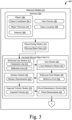
- Figs. 3 and 4 are an example data flow 300 of ghost object detection.
- the example data flow 300 may be implemented in any of the previously described environments and by any of the previously described systems or components.
- the example data flow 300 can be implemented in the example environments 100, 102 and/or by the example system 200.
- the example data flow 300 may also be implemented in other environments, by other systems or components, and utilizing other data flows or techniques.
- Example data flow 300 may be implemented by one or more entities (e.g., the detection module 112).
- the order in which the operations are shown and/or described is not intended to be construed as a limitation, and the order may be rearranged without departing from the scope of this disclosure.
- any number of the operations can be combined with any other number of the operations to implement the example data flow or an alternate data flow.
- the example data flow 300 starts with attributes 302 of an environment (e.g., example environments 100, 102) being obtained by the detection module 112.
- the attributes 302 include the objects 106 including their respective object coordinates 304, object velocities 110, and sensor(s) 306.
- the sensors 306 are indications of which of the vehicle sensors detected the respective objects. For example, many times, an object 106 may be detected by multiple sensors in respective locations relative to the host vehicle 104.
- the object coordinates 304 may be absolute coordinates (e.g., relative to the Earth) or relative to the host vehicle 104.
- the object coordinates 304 may be latitude and longitude coordinates, range and azimuth coordinates, lateral and longitudinal coordinates, or any other information that enables the host vehicle 104 to determine at least two-dimensional locations of the objects 106 relative to the host vehicle 104 (e.g., locations in or relative to a vehicle coordinate system (VCS)).
- the object velocities 110 may have respective speeds and directions, or speed vector components (e.g., lateral and longitudinal speeds).
- the attributes 302 also include the host velocity 108 and sensor locations 308 that are indicative of physical locations of the respective sensors 306.
- the attributes 302 may be acquired, received, or determined by the detection module 112.
- the detection module 112 may determine the attributes 302 directly from the sensor data 210, from a bus or interface connected to sensors that interface with the example system 200 (e.g., sensors 306), or from another module or system of the example system 200. Regardless of how or where the attributes 302 are gathered, received, derived, or calculated, the detection module 112 is configured to use the attributes 302 to determine which of the objects 106, if any, are ghost objects 114.
- the object pairing module 310 is configured to generate moving object pairs 312 of the objects 106.
- the object pairing module 310 may first determine which of the objects 106 are moving objects and which of the objects 106 are stationary objects. Then, the object pairing module 310 may generate the moving object pairs 312 from each combination of two of the moving objects responsive to determining that the host vehicle 104 is stationary. The object pairing module 310 may generate the moving object pairs 312 from each combination of the host vehicle 104 and the moving objects responsive to determining that the host vehicle 104 is reversing.
- the moving object pairs 312 contain respective first and second objects, the second object being at a further distance from the host vehicle 104. In the case of the host vehicle 104 reversing, the first object is the host vehicle 104.
- the second objects are potential ghost objects.
- the object pairing module 310 may look for moving objects that share the same sensors 306 (e.g., they are in a same field of view of one or more of the sensors 306). If the host vehicle 104 is reversing, such a determination may not be made (e.g., all of the moving objects in this scenario may satisfy the constraint).
- the object pairing module 310 may also look for range differences that are between certain values, e.g., ranges to second objects minus ranges to first objects that are between 0.5 to 20 meters. In some implementations, the range differences may be distances between the respective objects (instead of or in combination with differences in ranges to the host vehicle 104).
- the range differences may be the moving objects' respective ranges (e.g., because the host vehicle 104 has a location at the origin).
- the object pairing module 310 may also look for moving objects with object velocities 110 that are greater than a moving speed threshold, e.g., object velocities 110 are greater than 0.4 meters per second. If one or more of these criteria are not met for a pair of objects (e.g., two of the objects 106 if the host vehicle 104 is stationary or the host vehicle 104 and one of the objects 106 if the host vehicle 104 is reversing), the object pairing module 310 may not consider the pair of objects to be a moving object pair 312. Furthermore, if no suitable pairs of objects can be found (e.g., based on one or more of the criteria), the process may wait until a next cycle (e.g., none of the objects 106 in the current cycle may be determined to be ghost objects 114).
- a next cycle e.g., none of the objects 106 in the current cycle
- connection line 316 is a line that runs through centroids of the first and second objects of the respective moving object pair 312. If the host vehicle 104 is reversing, the connection line 316 may run through an origin of the VCS to the centroid of the second object of the moving object pair 312.
- the reflection line 318 is a line that runs through a midpoint of a segment of the connection line 316 between the first and second points and is perpendicular to the connection line 316. In general, the reflection line 318 represents a potential reflection surface if the second object of the moving object pair 312 is a ghost object 114. Details of the connection line 316 and the reflection line 318 are shown in Fig. 5 .
- an area module 320 determines whether any of the stationary objects are within an area of the connection line 316 and the reflection line 318.
- the area may be rectangular and aligned with the connection line 316 and the reflection line 318.
- the stationary objects that are within the area become area stationary objects 322.
- the area module 320 may only indicate stationary objects within the area as being area stationary objects 322 responsive to determining that a plurality of the stationary objects are within the area (e.g., five). If one or a plurality of the stationary objects (depending upon implementation) are not within the area, no area stationary objects 322 are indicated, and the process may move to the next moving object pair 312 (e.g., the second object is not considered to be a ghost object 114). Details of the area are shown in Fig. 6 .
- a reflection point module 324 determines a reflection point 326 indicative of a potential reflection point for a ghost detection of the second object.
- the reflection point 326 may be at an intersection of a signal line that runs through the centroid of the second object and a location of the host vehicle 104 and the reflection line 318.
- the location on the host vehicle 104 may be a virtual sensor location that is at an average location between the sensors 306 of the first and second objects (relative to a VCS). If only one sensor detects the first and second objects (or the second object if the host vehicle 104 is reversing), then the virtual sensor location may be the sensor location.
- the process may move to the next moving object pair 312 (e.g., the second object is not considered to be a ghost object 114). Details of the reflection point 326 are shown in Fig. 7 .
- a distance module 328 generates a distance determination 330 (yes/no) based on whether any of the area stationary objects 322 are within a distance of the reflection point 326 (e.g., within 3 meters of the reflection point 326). If any of the area stationary objects 322 are within the distance of the reflection point 326, then the distance determination 330 is yes. If none of the area stationary objects 322 are within the distance of the reflection point 326, then the distance determination 330 is no. If the distance determination 330 is no, the process may move to the next moving object pair 312 (e.g., the second object is not considered to be a ghost object 114). Details of the distance are shown in Fig. 8 .
- an expected velocity module 332 generates an expected velocity 334 for the second object.
- the expected velocity 334 is indicative of an expected velocity of the second object if the second object is a ghost of the first object or the host vehicle 104). Details of the expected velocity 334 are shown in Fig. 9
- a ghost determination module 336 generates a ghost determination 338 (yes/no) based on the object velocity 110 of the second object and the expected velocity 334.
- the ghost determination module 336 may determine whether a speed and/or two vector speeds of the object velocity 110 of the second object are within a differential speed of a speed and/or two vector speeds of the expected velocity 334. Equations 1 show two example conditions indicative of the comparison, one or both of which may be used to generate the ghost determination 338.
- the process may move to the next moving object pair 312 (e.g., the second object is not considered to be a ghost object 114). If the ghost determination 338 is yes, the second object of the respective moving object pair 312 is likely a ghost object 114.
- the process above may be repeated for other moving object pairs 312 to generate indications of likely ghost objects for the current frame. It should be noted that the first object of one moving object pair 312 may be the second object of another moving object pair 312.
- a ghost probability module 340 may track probabilities 342 of the objects 106.
- the probabilities 342 are indicative of probabilities that the objects 106 are ghost objects 114.
- only the moving objects may have probabilities 342.
- the indications of likely ghost objects for the current frame e.g., all second objects that had a ghost determination 338 of yes for the current frame
- the objects 106 or the moving objects may start (e.g., in the first detected frame) with probabilities of 0.5.
- the probabilities 342 may be updated according to Equations 2.
- an object classification module 344 may generate indications of which of the objects 106 are ghost objects 114.
- the object classification module 344 may generate the indications when the probabilities 342 reach a probability threshold (e.g., 0.8). By using probabilities and tracking the ghost determinations 338 over time, the object classification module 344 can more reliably determine the ghost objects 114.
- indications of the objects 106 e.g., real objects, ghost objects 114, or some combination thereof
- the detection module 112 is able to identify ghost objects 114 when the host vehicle 104 is stationary and when it is moving without any a priori information about the environment and without sensor fusion or complicated object trackers. In doing so, the detection module 112 may be able to efficiently identify the ghost objects 114 (and possibly filter them out) in a wide variety of environments such that downstream operations can function as designed.
- Figs 5A-9 illustrate example aspects of the process discussed above.
- the example illustrations correspond to the example environments of Fig. 1 .
- example illustrations 500, 502 correspond to example environments 100, 102, respectively
- example illustrations 600, 602 correspond to example environments 100, 102, respectively, and so on.
- the following is not limited to those two environments, however.
- the objects 106 may be in any orientation relative to the host vehicle 104 and have any object velocities 110 without departing from the scope of this disclosure.
- Figs. 5A and 5B illustrate, at example illustrations 500 and 502, respectively, example connection lines 316 and reflection lines 318.
- the host vehicle 104 has a VCS 504.
- the VCS may have longitudinal and lateral axes and an origin at a center of a front bumper of the host vehicle 104. Different axes and/or origins may be used without departing from the scope of this disclosure.
- the connection line 316 is illustrated as going through the centroids of the first and second objects of illustration 500 (e.g., objects 106-a and 106-b).
- the connection line 316 is illustrated as going through the origin of the VCS 504 and the centroid of the second object of illustration 502 (e.g., object 106-b).
- Objects 106-a and 106-b have object coordinates 304 relative to the VCS 504 (e.g., lateral/longitudinal).
- the object coordinates 304 are used to determine the connection line 316.
- the reflection line 318 is at a midpoint of a segment of the connection line 316 between the two objects (e.g., centroids of objects 106-a and 106-b or origin of VCS 504 and centroid of 106-b) and at a right angle to the connection line.
- the reflection line 318 may be given by Equation 3.
- a 1 ⁇ long + b 1 ⁇ lat + c 1 0
- a 1 2( long b - long a )
- b 1 2( lat b - lat a )
- c 1 ( long a 2 + lat a 2 )-( long b 2 + lat b 2 ).
- Figs. 6A and 6B illustrate, at example illustrations 600 and 602, respectively, example area stationary objects 322.
- the area 604 (for determining the area stationary objects 322) may be centered on the intersection of the connection line 316 and reflection line 318.
- the area 604 may also be rectangular and oriented such that a length is parallel to the reflection line 318 and a width is parallel to the connection line 316.
- the length may be on the order of five times the width. For example, the length may be 20 meters and the width may be 4 meters.
- each of the stationary objects may be projected onto the connection line 316 along with the first and second objects.
- the projected stationary objects should be within half the width of the area 604 of the middle point between the projected first and second objects.
- Each of the stationary objects may also be projected onto the reflection line 318 along with the first and second objects (will be a single point because the connection line 316 and reflection line 318 are perpendicular).
- the projected stationary objects should be within half the length of the area 604 of the projected first and second objects. Projecting the objects 106 onto the connection line 316 and the reflection line 318 is just one technique of determining whether the stationary objects are within the area 604. Other techniques may be used (e.g., coordinate conversion, axes rotation, graphical analysis) without departing from the scope of this disclosure.
- object 106-c is within the area 604, as object 106-c is a reflecting object (as stated in Fig. 1A or 1B ). Although a single point is shown, object 106-c may provide multiple points with any number of them being within the area 604. For example, the object 106-c may comprise ten objects 106, where five of them are within the area 604. Again, any of the stationary objects that are within the area 604 become the area stationary objects 322 (e.g., object 106-c).
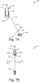
- Figs. 7A and 7B illustrate, at example illustrations 700 and 702, respectively, example reflection points 326.
- the signal line 704 is generated.
- the signal line 704 passes through the centroid of the second object (e.g., object 106-b) and a virtual sensor location 706.
- the virtual sensor location 706 is based on an average position (relative to the VCS 504) of the respective sensors 306 that detected the second object.
- a lateral coordinate of the virtual sensor location 706 may be a sum of the lateral coordinates of the sensor locations 308 of the sensors 306 that detected the second object divided by two
- a longitudinal coordinate of the virtual sensor location 706 may be a sum of the longitudinal coordinates of the sensors 306 that detected the second object divided by two.
- the second object is detected by sensors 306-a and 306-b
- the second object is detected by sensors 306-b and 306-c. If only one sensor 306 detects the second object, then the virtual sensor location 706 may be the sensor location 308 of the sensor 306.
- the reflection point 326 is at an intersection of the signal line 704 and the reflection line 318. If abs ( b 1 * a 2 - a 1 * b 2) ⁇ 0.001 then the reflection point 326 may not be determined and the process may move to the next moving object pair 312 (e.g., the second object may not be a ghost object 114). If abs ( b 1 ⁇ a 2 - a 1 ⁇ b 2) ⁇ 0.001 then the reflection point 326 can be determined by Equations 5.
- Figs. 8A and 8B illustrate, at example illustrations 800 and 802, respectively, example distance determinations 330.
- the distance 804 may be a fixed constant (e.g., three meters).
- object 106-c is within the distance 804, thus, the distance determination 330 for object 106-c is a yes.
- Figs. 9A and 9B illustrate, at example illustrations 900 and 902, respectively, example expected velocities 334.
- the expected velocity 334 may be determined by Equation 6.
- egv long is the longitudinal component of the expected velocity 334
- egv lat is the lateral component of the expected velocity 334
- va long is the longitudinal component of the object velocity 110 of the first object (e.g., object velocity 110-a or host velocity 108)
- va lat is the
- object 106-b is a ghost object 114
- the expected velocity 334 generally aligns with the object velocity 110-b.
- the object 106-b may be indicated as a ghost object 114 and either sent to the vehicle component 116 or filtered out of the objects 106 that are sent to the vehicle component 116.
- the host vehicle 104 is able to accurately determine which of the objects 106 are ghost objects 114 while stationary or moving without any other knowledge of an environment around the host vehicle 104 (e.g., that there is a guardrail present). Furthermore, the host vehicle 104 can accomplish ghost object detection without unnecessary movement or multiple sensors 306 (although multiple sensors 306 have been described as detecting the second object, the process works similarly if the second object is only detected by a single sensor 306). Thus, the host vehicle 104 can quickly and effectively identify ghost objects 114 in a broad range of environments.
- Fig. 10 is an example method 1000 for ghost object detection.
- the example method 1000 may be implemented in any of the previously described environments, by any of the previously described systems or components, and by utilizing any of the previously described data flows, process flows, or techniques.
- the example method 1000 can be implemented in the example environments of Fig. 1A and 1B , by the example system 200, by following the example data flow 300, and/or as illustrated in the example illustrations of Figs. 5-9 .
- the example method 1000 may also be implemented in other environments, by other systems or components, and utilizing other data flows, process flows, or techniques.
- Example method 1000 may be implemented by one or more entities (e.g., the detection module 112).
- the object pairing module 310 may receive the attributes 302, including the objects 106 and their respective attributes (e.g., object coordinates 304, object velocities 110, and sensors 306).
- a reflection line indicative of a potential reflection surface between first and second moving objects is determined.
- the reflection line module 314 may determine the reflection line 318 based on a portion of the connection line 316 between the first and second moving objects.
- the area module 320 may determine that there are one or more area stationary objects 322. In some implementations, the area module 320 may determine that there are a plurality of area stationary objects 322.
- the distance module 328 may determine that one or more of the area stationary objects 322 are within the distance 804 of the reflection point 326 and provide the distance determination 330 of yes.
- an expected velocity of the second object is determined based on the first object and the reflection line.
- the expected velocity module 332 may determine the expected velocity 334 based on the object velocity 110 of the second object and the reflection line 318.
- the ghost determination module 336 may determine that one or more speeds of the object velocity 110 of the second object are within the differential speed of one or more speeds of the expected velocity 334 and provide the ghost determination 338 of yes. Responsive to the ghost determination 338 of yes, the second object may be indicated as a ghost object 114 (e.g., by the object classification module 344). In some implementations, the ghost determination 338 may be used by the ghost probability module 340 to update a current probability 342 of the second object (e.g., from previous frames). The object classification module 344 may then indicate that the second object is a ghost object 114 responsive to determining that the probability 342 of the second object surpasses a threshold.
- an indication that the second object is a ghost object is output.
- the object classification module 344 may output indications of the ghost objects 114, the real objects (e.g., objects 106 other than the ghost objects 114), or some combination thereof.
- Example 1 A method comprising: receiving information about a plurality of objects proximate a host vehicle, the objects comprising two or more moving objects and one or more stationary objects; determining one or more moving object pairs of the moving objects; and for each of the moving object pairs: determining a reflection line that is: perpendicular to a connection line connecting a first object and a second object of the respective moving object pair; and between the first object and the second object; determining whether one or more of the stationary objects are within an area of an intersection of the connection line and the reflection line; and based on a determination that one or more of the stationary objects are within the area: determining whether one or more of the one or more of the stationary objects are within a distance of a reflection point that is at an intersection of: a signal line between the second object and the host vehicle; and the reflection line; and based on a determination that one or more of the one or more stationary objects are within the distance: determining, based on the first object and the reflection line, an expected velocity of the second object; determining whether a
- Example 2 The method of example 1, wherein the host vehicle is stationary.
- Example 3 The method of example 1 or 2, wherein: the host vehicle is reversing; and the first object is the host vehicle.
- Example 4 The method of example 1, 2, or 3, wherein the determining the moving object pairs comprises determining pairs of the moving objects that: have a difference in range within a span; and have speeds greater than a moving speed threshold.
- Example 5 The method of any preceding example, wherein the area comprises a rectangular area that: is parallel to the reflection line; has a length centered on the connection line; and has a width centered on the reflection line, the width being smaller than the length.
- Example 6 The method of any preceding example, wherein the determining whether one or more of the stationary objects are within the area comprises: projecting the stationary objects along with the first object and the second object to the connection line; and projecting the stationary objects to the reflection line.
- Example 7 The method of any preceding example, wherein the length is around five times the width.
- Example 8 The method of any preceding example, wherein the determining whether one or more of the stationary objects are within the area comprises determining that a plurality of the stationary objects are within the area.
- Example 9 The method of any preceding example, wherein the signal line is between the second object and a virtual sensor, the virtual sensor comprising a centroid of one or more sensors that detected the second object.
- Example 10 The method of any preceding example, wherein the information is received from a RADAR or LIDAR system, module, or component.
- Example 11 The method of any preceding example, wherein the expected velocity is based further on a velocity of the first object and an angle of the reflection line.
- Example 12 The method of any preceding example, wherein the determining whether the velocity of the second object is within the differential speed of the expected velocity comprises: determining whether a speed of the second object is within the differential speed of a speed of the expected velocity; and determining whether speeds of the second object in two directions are within the differential speed of speeds of the expected velocity in the two directions.
- Example 13 The method of any preceding example, further comprising, based on the velocity of the second object being within the differential speed of the expected velocity, updating a probability that the second object is a ghost object, wherein the indication is based on the probability.
- Example 14 A method comprising: receiving information about a plurality of objects proximate a host vehicle, the objects comprising first and second moving objects and one or more stationary objects; determining a reflection line indicative of a potential reflection surface between the first and second moving objects; determining that one or more of the stationary objects are within an area of the reflection line proximate the first and second objects; determining that one or more of the one or more of the stationary objects are within a distance of a reflection point indicative of a potential reflection point on the reflection line; determining, based on the first object and the reflection line, an expected velocity of the second object; determining, based on the velocity of the second object being within a differential speed of the expected velocity, that the second object is a ghost object; and outputting an indication that the second object is a ghost object.
- Example 15 A system comprising at least one processor configured to: receive information about a plurality of objects proximate a host vehicle, the objects comprising two or more moving objects and one or more stationary objects; determine one or more moving object pairs of the moving objects; and for each of the moving object pairs: determine a reflection line that is: perpendicular to a connection line connecting a first object and a second object of the respective moving object pair; and between the first object and the second object; determine whether one or more of the stationary objects are within an area of an intersection of the connection line and the reflection line; and based on a determination that one or more of the stationary objects are within the area: determine whether one or more of the one or more of the stationary objects are within a distance of a reflection point that is at an intersection of: a signal line between the second object and the host vehicle; and the reflection line; and based on a determination that one or more of the one or more stationary objects are within the distance: determine, based on the first object and the reflection line, an expected velocity of the second object; determine whether a
- Example 16 The system of example 15, wherein the host vehicle is stationary.
- Example 17 The system of example 15 or 16, wherein: the host vehicle is reversing; and the first object is the host vehicle.
- Example 18 The system of example 15, 16, or 17, wherein the determination of whether one or more of the stationary objects are within the area comprises: projecting the stationary objects along with the first object and the second object to the connection line; and projecting the stationary objects to the reflection line.
- Example 19 The system of any of examples 15-18, wherein the signal line is between the second object and a virtual sensor, the virtual sensor comprising a centroid of one or more sensors that detected the second object.
- Example 20 The system of any of examples 15-19, wherein the expected velocity is based further on a velocity of the first object and an angle of the reflection line relative to the host vehicle.
- Example 21 Computer-readable storage media comprising instructions that, when executed, cause at least one processor to: receive information about a plurality of objects proximate a host vehicle, the objects comprising two or more moving objects and one or more stationary objects; determine one or more moving object pairs of the moving objects; and for each of the moving object pairs: determine a reflection line that is: perpendicular to a connection line connecting a first object and a second object of the respective moving object pair; and between the first object and the second object; determine whether one or more of the stationary objects are within an area of an intersection of the connection line and the reflection line; and based on a determination that one or more of the stationary objects are within the area: determine whether one or more of the one or more of the stationary objects are within a distance of a reflection point that is at an intersection of: a signal line between the second object and the host vehicle; and the reflection line; and based on a determination that one or more of the one or more stationary objects are within the distance: determine, based on the first object and the reflection line, an expected velocity
- Example 22 A system comprising: at least one processor configured to perform the method of any of examples 1-14.
- Example 23 Computer-readable storage media comprising instructions that, when executed, cause at least one processor to perform the method of any of examples 1-14.
- Example 24 A system comprising means for performing the method of any of examples 1-14.
- Example 25 A method performed by the system of any of examples 15-20.
- Example, 26 A method comprised by the instructions of example 21.
- "at least one of: a, b, or c” is intended to cover a, b, c, a-b, a-c, b-c, and a-b-c, as well as any combination with multiples of the same element (e.g., a-a, a-a-a, a-a-b, a-a-c, a-b-b, a-c-c, b-b, b-b-b, b-b-c, c-c, and c-c-c or any other ordering of a, b, and c).
Landscapes
- Engineering & Computer Science (AREA)
- Radar, Positioning & Navigation (AREA)
- Remote Sensing (AREA)
- Physics & Mathematics (AREA)
- Computer Networks & Wireless Communication (AREA)
- General Physics & Mathematics (AREA)
- Electromagnetism (AREA)
- Traffic Control Systems (AREA)
- Radar Systems Or Details Thereof (AREA)
Applications Claiming Priority (2)
| Application Number | Priority Date | Filing Date | Title |
|---|---|---|---|
| US202263266937P | 2022-01-19 | 2022-01-19 | |
| US17/651,859 US12140666B2 (en) | 2022-01-19 | 2022-02-21 | Ghost object detection |
Publications (2)
| Publication Number | Publication Date |
|---|---|
| EP4215934A1 true EP4215934A1 (fr) | 2023-07-26 |
| EP4215934B1 EP4215934B1 (fr) | 2025-08-27 |
Family
ID=83594061
Family Applications (1)
| Application Number | Title | Priority Date | Filing Date |
|---|---|---|---|
| EP22199449.4A Active EP4215934B1 (fr) | 2022-01-19 | 2022-10-04 | Détection d'objets fantômas dans les véhicules |
Country Status (3)
| Country | Link |
|---|---|
| US (1) | US12140666B2 (fr) |
| EP (1) | EP4215934B1 (fr) |
| CN (1) | CN116466303B (fr) |
Families Citing this family (1)
| Publication number | Priority date | Publication date | Assignee | Title |
|---|---|---|---|---|
| KR20240118209A (ko) * | 2023-01-20 | 2024-08-05 | 주식회사 에이치엘클레무브 | 차량용 레이더 다중 반사 신호에 의한 허위 타겟 삭제 방법 및 허위 타겟 삭제 시스템 |
Citations (1)
| Publication number | Priority date | Publication date | Assignee | Title |
|---|---|---|---|---|
| US20200278435A1 (en) * | 2019-02-28 | 2020-09-03 | Zoox, Inc. | Recognizing radar reflections using position information |
Family Cites Families (8)
| Publication number | Priority date | Publication date | Assignee | Title |
|---|---|---|---|---|
| JP5018943B2 (ja) * | 2010-09-07 | 2012-09-05 | 株式会社デンソー | レーダ装置 |
| US9810782B2 (en) | 2015-03-20 | 2017-11-07 | Delphi Technologies, Inc. | Vehicle radar system with image reflection detection |
| JP6970936B2 (ja) * | 2016-12-20 | 2021-11-24 | パナソニックIpマネジメント株式会社 | 物体検出装置、物体検出プログラム、および記録媒体 |
| WO2019012098A1 (fr) * | 2017-07-13 | 2019-01-17 | Iee International Electronics & Engineering S.A. | Procédé et système de détection de cible et véhicule comprenant lesdits procédé et système |
| WO2020176483A1 (fr) * | 2019-02-28 | 2020-09-03 | Zoox, Inc. | Reconnaissance de réflexions radar à l'aide d'informations de vitesse et de position |
| US11300677B2 (en) * | 2019-07-08 | 2022-04-12 | GM Global Technology Operations LLC | Automated driving systems and control logic for host vehicle velocity estimation using wide aperture radar |
| US11408995B2 (en) * | 2020-02-24 | 2022-08-09 | Aptiv Technologies Limited | Lateral-bin monitoring for radar target detection |
| US11415670B2 (en) * | 2020-03-20 | 2022-08-16 | Aptiv Technologies Limited | Object classification using low-level radar data |
-
2022
- 2022-02-21 US US17/651,859 patent/US12140666B2/en active Active
- 2022-10-04 EP EP22199449.4A patent/EP4215934B1/fr active Active
- 2022-12-12 CN CN202211597479.2A patent/CN116466303B/zh active Active
Patent Citations (1)
| Publication number | Priority date | Publication date | Assignee | Title |
|---|---|---|---|---|
| US20200278435A1 (en) * | 2019-02-28 | 2020-09-03 | Zoox, Inc. | Recognizing radar reflections using position information |
Also Published As
| Publication number | Publication date |
|---|---|
| US12140666B2 (en) | 2024-11-12 |
| EP4215934B1 (fr) | 2025-08-27 |
| CN116466303A (zh) | 2023-07-21 |
| CN116466303B (zh) | 2026-01-06 |
| US20230243960A1 (en) | 2023-08-03 |
Similar Documents
| Publication | Publication Date | Title |
|---|---|---|
| US9937905B2 (en) | Side collision avoidance system and method for vehicle | |
| EP3070493B1 (fr) | Système de radar de véhicule avec détection de réflexion d'images | |
| CN108694860B (zh) | 注意提醒装置 | |
| US11292464B2 (en) | Apparatus for a driver assistance system | |
| EP3282278B1 (fr) | Dispositif de calcul radar-installation-angle, appareil radar, et procédé de calcul radar-installation-angle | |
| Dagan et al. | Forward collision warning with a single camera | |
| US9983306B2 (en) | System and method for providing target threat assessment in a collision avoidance system on a vehicle | |
| EP2590152B1 (fr) | Dispositif permettant d'estimer l'itinéraire de circulation d'un véhicule | |
| EP2333484B1 (fr) | Dispositif de détermination de voie et système de navigation | |
| US11891081B2 (en) | Warning apparatus | |
| US10255814B2 (en) | Driving assistance apparatus | |
| JP2007304034A (ja) | 車載道路形状識別装置 | |
| US20130179047A1 (en) | Intersection collision avoidance with adaptable vehicle dimensions | |
| US20050197770A1 (en) | Collision detection system and method of estimating target crossing location | |
| CN111383477A (zh) | 信息提示装置 | |
| CN114942430B (zh) | 用于传感器数据的基于多假设的融合的方法和系统 | |
| US20190204415A1 (en) | Determining relative velocity in a vehicle radar system | |
| EP3537174A1 (fr) | Procédé et système permettant de déterminer l'angle de pointage d'un objet en mouvement | |
| CN109345870A (zh) | 预防车辆碰撞的预警方法及装置 | |
| EP4215934A1 (fr) | Détection d'objets fantômas dans les véhicules | |
| CN116736243A (zh) | 使用多种假设的稳定的雷达跟踪速度初始化 | |
| US12092723B2 (en) | Target-velocity estimation using position variance | |
| EP4332624A1 (fr) | Association de voies basée sur des erreurs d'extension azimutale et de compacité | |
| EP1265078A2 (fr) | Perfectionnements par rapport aux systèmes de renseignements d'avertissements d'obstacles | |
| US12145581B2 (en) | Collision indication based on yaw rate and lateral velocity thresholds |
Legal Events
| Date | Code | Title | Description |
|---|---|---|---|
| PUAI | Public reference made under article 153(3) epc to a published international application that has entered the european phase |
Free format text: ORIGINAL CODE: 0009012 |
|
| STAA | Information on the status of an ep patent application or granted ep patent |
Free format text: STATUS: THE APPLICATION HAS BEEN PUBLISHED |
|
| AK | Designated contracting states |
Kind code of ref document: A1 Designated state(s): AL AT BE BG CH CY CZ DE DK EE ES FI FR GB GR HR HU IE IS IT LI LT LU LV MC ME MK MT NL NO PL PT RO RS SE SI SK SM TR |
|
| STAA | Information on the status of an ep patent application or granted ep patent |
Free format text: STATUS: REQUEST FOR EXAMINATION WAS MADE |
|
| 17P | Request for examination filed |
Effective date: 20231024 |
|
| RBV | Designated contracting states (corrected) |
Designated state(s): AL AT BE BG CH CY CZ DE DK EE ES FI FR GB GR HR HU IE IS IT LI LT LU LV MC ME MK MT NL NO PL PT RO RS SE SI SK SM TR |
|
| RAP1 | Party data changed (applicant data changed or rights of an application transferred) |
Owner name: APTIV TECHNOLOGIES AG |
|
| RAP3 | Party data changed (applicant data changed or rights of an application transferred) |
Owner name: APTIV TECHNOLOGIES AG |
|
| GRAP | Despatch of communication of intention to grant a patent |
Free format text: ORIGINAL CODE: EPIDOSNIGR1 |
|
| STAA | Information on the status of an ep patent application or granted ep patent |
Free format text: STATUS: GRANT OF PATENT IS INTENDED |
|
| INTG | Intention to grant announced |
Effective date: 20250320 |
|
| GRAS | Grant fee paid |
Free format text: ORIGINAL CODE: EPIDOSNIGR3 |
|
| GRAA | (expected) grant |
Free format text: ORIGINAL CODE: 0009210 |
|
| STAA | Information on the status of an ep patent application or granted ep patent |
Free format text: STATUS: THE PATENT HAS BEEN GRANTED |
|
| P01 | Opt-out of the competence of the unified patent court (upc) registered |
Free format text: CASE NUMBER: UPC_APP_0335_4215934/2025 Effective date: 20250715 |
|
| AK | Designated contracting states |
Kind code of ref document: B1 Designated state(s): AL AT BE BG CH CY CZ DE DK EE ES FI FR GB GR HR HU IE IS IT LI LT LU LV MC ME MK MT NL NO PL PT RO RS SE SI SK SM TR |
|
| REG | Reference to a national code |
Ref country code: CH Ref legal event code: EP |
|
| REG | Reference to a national code |
Ref country code: DE Ref legal event code: R096 Ref document number: 602022020133 Country of ref document: DE |
|
| REG | Reference to a national code |
Ref country code: IE Ref legal event code: FG4D |
|
| PGFP | Annual fee paid to national office [announced via postgrant information from national office to epo] |
Ref country code: FR Payment date: 20250910 Year of fee payment: 4 |
|
| REG | Reference to a national code |
Ref country code: NL Ref legal event code: MP Effective date: 20250827 |
|
| PG25 | Lapsed in a contracting state [announced via postgrant information from national office to epo] |
Ref country code: IS Free format text: LAPSE BECAUSE OF FAILURE TO SUBMIT A TRANSLATION OF THE DESCRIPTION OR TO PAY THE FEE WITHIN THE PRESCRIBED TIME-LIMIT Effective date: 20251227 |
|
| PGFP | Annual fee paid to national office [announced via postgrant information from national office to epo] |
Ref country code: DE Payment date: 20250917 Year of fee payment: 4 |
|
| PG25 | Lapsed in a contracting state [announced via postgrant information from national office to epo] |
Ref country code: NO Free format text: LAPSE BECAUSE OF FAILURE TO SUBMIT A TRANSLATION OF THE DESCRIPTION OR TO PAY THE FEE WITHIN THE PRESCRIBED TIME-LIMIT Effective date: 20251127 |
|
| REG | Reference to a national code |
Ref country code: LT Ref legal event code: MG9D |
|
| PG25 | Lapsed in a contracting state [announced via postgrant information from national office to epo] |
Ref country code: PT Free format text: LAPSE BECAUSE OF FAILURE TO SUBMIT A TRANSLATION OF THE DESCRIPTION OR TO PAY THE FEE WITHIN THE PRESCRIBED TIME-LIMIT Effective date: 20251229 |
|
| PG25 | Lapsed in a contracting state [announced via postgrant information from national office to epo] |
Ref country code: FI Free format text: LAPSE BECAUSE OF FAILURE TO SUBMIT A TRANSLATION OF THE DESCRIPTION OR TO PAY THE FEE WITHIN THE PRESCRIBED TIME-LIMIT Effective date: 20250827 |
|
| PG25 | Lapsed in a contracting state [announced via postgrant information from national office to epo] |
Ref country code: HR Free format text: LAPSE BECAUSE OF FAILURE TO SUBMIT A TRANSLATION OF THE DESCRIPTION OR TO PAY THE FEE WITHIN THE PRESCRIBED TIME-LIMIT Effective date: 20250827 Ref country code: NL Free format text: LAPSE BECAUSE OF FAILURE TO SUBMIT A TRANSLATION OF THE DESCRIPTION OR TO PAY THE FEE WITHIN THE PRESCRIBED TIME-LIMIT Effective date: 20250827 |
|
| PG25 | Lapsed in a contracting state [announced via postgrant information from national office to epo] |
Ref country code: GR Free format text: LAPSE BECAUSE OF FAILURE TO SUBMIT A TRANSLATION OF THE DESCRIPTION OR TO PAY THE FEE WITHIN THE PRESCRIBED TIME-LIMIT Effective date: 20251128 |
|
| PG25 | Lapsed in a contracting state [announced via postgrant information from national office to epo] |
Ref country code: SE Free format text: LAPSE BECAUSE OF FAILURE TO SUBMIT A TRANSLATION OF THE DESCRIPTION OR TO PAY THE FEE WITHIN THE PRESCRIBED TIME-LIMIT Effective date: 20250827 |
|
| PG25 | Lapsed in a contracting state [announced via postgrant information from national office to epo] |
Ref country code: LV Free format text: LAPSE BECAUSE OF FAILURE TO SUBMIT A TRANSLATION OF THE DESCRIPTION OR TO PAY THE FEE WITHIN THE PRESCRIBED TIME-LIMIT Effective date: 20250827 |
|
| PG25 | Lapsed in a contracting state [announced via postgrant information from national office to epo] |
Ref country code: PL Free format text: LAPSE BECAUSE OF FAILURE TO SUBMIT A TRANSLATION OF THE DESCRIPTION OR TO PAY THE FEE WITHIN THE PRESCRIBED TIME-LIMIT Effective date: 20250827 Ref country code: BG Free format text: LAPSE BECAUSE OF FAILURE TO SUBMIT A TRANSLATION OF THE DESCRIPTION OR TO PAY THE FEE WITHIN THE PRESCRIBED TIME-LIMIT Effective date: 20250827 |
|
| PG25 | Lapsed in a contracting state [announced via postgrant information from national office to epo] |
Ref country code: RS Free format text: LAPSE BECAUSE OF FAILURE TO SUBMIT A TRANSLATION OF THE DESCRIPTION OR TO PAY THE FEE WITHIN THE PRESCRIBED TIME-LIMIT Effective date: 20251127 |
|
| PG25 | Lapsed in a contracting state [announced via postgrant information from national office to epo] |
Ref country code: ES Free format text: LAPSE BECAUSE OF FAILURE TO SUBMIT A TRANSLATION OF THE DESCRIPTION OR TO PAY THE FEE WITHIN THE PRESCRIBED TIME-LIMIT Effective date: 20250827 |
|
| REG | Reference to a national code |
Ref country code: AT Ref legal event code: MK05 Ref document number: 1830518 Country of ref document: AT Kind code of ref document: T Effective date: 20250827 |
|
| PG25 | Lapsed in a contracting state [announced via postgrant information from national office to epo] |
Ref country code: RO Free format text: LAPSE BECAUSE OF FAILURE TO SUBMIT A TRANSLATION OF THE DESCRIPTION OR TO PAY THE FEE WITHIN THE PRESCRIBED TIME-LIMIT Effective date: 20250827 |
|
| PG25 | Lapsed in a contracting state [announced via postgrant information from national office to epo] |
Ref country code: SM Free format text: LAPSE BECAUSE OF FAILURE TO SUBMIT A TRANSLATION OF THE DESCRIPTION OR TO PAY THE FEE WITHIN THE PRESCRIBED TIME-LIMIT Effective date: 20250827 |
|
| PG25 | Lapsed in a contracting state [announced via postgrant information from national office to epo] |
Ref country code: DK Free format text: LAPSE BECAUSE OF FAILURE TO SUBMIT A TRANSLATION OF THE DESCRIPTION OR TO PAY THE FEE WITHIN THE PRESCRIBED TIME-LIMIT Effective date: 20250827 |
|
| PG25 | Lapsed in a contracting state [announced via postgrant information from national office to epo] |
Ref country code: AT Free format text: LAPSE BECAUSE OF FAILURE TO SUBMIT A TRANSLATION OF THE DESCRIPTION OR TO PAY THE FEE WITHIN THE PRESCRIBED TIME-LIMIT Effective date: 20250827 |
|
| PG25 | Lapsed in a contracting state [announced via postgrant information from national office to epo] |
Ref country code: IT Free format text: LAPSE BECAUSE OF FAILURE TO SUBMIT A TRANSLATION OF THE DESCRIPTION OR TO PAY THE FEE WITHIN THE PRESCRIBED TIME-LIMIT Effective date: 20250827 |
|
| PG25 | Lapsed in a contracting state [announced via postgrant information from national office to epo] |
Ref country code: CZ Free format text: LAPSE BECAUSE OF FAILURE TO SUBMIT A TRANSLATION OF THE DESCRIPTION OR TO PAY THE FEE WITHIN THE PRESCRIBED TIME-LIMIT Effective date: 20250827 |
|
| PG25 | Lapsed in a contracting state [announced via postgrant information from national office to epo] |
Ref country code: SK Free format text: LAPSE BECAUSE OF FAILURE TO SUBMIT A TRANSLATION OF THE DESCRIPTION OR TO PAY THE FEE WITHIN THE PRESCRIBED TIME-LIMIT Effective date: 20250827 Ref country code: EE Free format text: LAPSE BECAUSE OF FAILURE TO SUBMIT A TRANSLATION OF THE DESCRIPTION OR TO PAY THE FEE WITHIN THE PRESCRIBED TIME-LIMIT Effective date: 20250827 |