EP4215954B1 - Capteur optique - Google Patents
Capteur optique Download PDFInfo
- Publication number
- EP4215954B1 EP4215954B1 EP22152804.5A EP22152804A EP4215954B1 EP 4215954 B1 EP4215954 B1 EP 4215954B1 EP 22152804 A EP22152804 A EP 22152804A EP 4215954 B1 EP4215954 B1 EP 4215954B1
- Authority
- EP
- European Patent Office
- Prior art keywords
- tube
- optical sensor
- optical
- sensor according
- receiver
- Prior art date
- Legal status (The legal status is an assumption and is not a legal conclusion. Google has not performed a legal analysis and makes no representation as to the accuracy of the status listed.)
- Active
Links
Images


Classifications
-
- G—PHYSICS
- G01—MEASURING; TESTING
- G01V—GEOPHYSICS; GRAVITATIONAL MEASUREMENTS; DETECTING MASSES OR OBJECTS; TAGS
- G01V8/00—Prospecting or detecting by optical means
- G01V8/10—Detecting, e.g. by using light barriers
- G01V8/12—Detecting, e.g. by using light barriers using one transmitter and one receiver
-
- G—PHYSICS
- G01—MEASURING; TESTING
- G01S—RADIO DIRECTION-FINDING; RADIO NAVIGATION; DETERMINING DISTANCE OR VELOCITY BY USE OF RADIO WAVES; LOCATING OR PRESENCE-DETECTING BY USE OF THE REFLECTION OR RERADIATION OF RADIO WAVES; ANALOGOUS ARRANGEMENTS USING OTHER WAVES
- G01S17/00—Systems using the reflection or reradiation of electromagnetic waves other than radio waves, e.g. lidar systems
- G01S17/02—Systems using the reflection of electromagnetic waves other than radio waves
- G01S17/06—Systems determining position data of a target
- G01S17/08—Systems determining position data of a target for measuring distance only
-
- G—PHYSICS
- G01—MEASURING; TESTING
- G01V—GEOPHYSICS; GRAVITATIONAL MEASUREMENTS; DETECTING MASSES OR OBJECTS; TAGS
- G01V8/00—Prospecting or detecting by optical means
- G01V8/10—Detecting, e.g. by using light barriers
- G01V8/20—Detecting, e.g. by using light barriers using multiple transmitters or receivers
Definitions
- the invention relates to an optical sensor.
- Such optical sensors are generally used to detect objects in a surveillance area.
- the optical sensor has only one transmitter that emits light beams and one receiver that receives light beams.
- the optical sensor can be designed as a light sensor, distance sensor or reflection light barrier and the like, with the transmitter and receiver being integrated in a common housing in these embodiments.
- the optical sensor can also be designed as a light barrier. In this case, the transmitter and receiver are housed in separate housings.
- the optical sensor can also have several transmitters and/or receivers.
- An example of such an optical sensor is a light curtain.
- the light curtain typically comprises a series arrangement of light beam emitting transmitters in a first housing at one edge of the monitoring area and a series arrangement of light beam receiving receivers in a second housing at the opposite edge of the monitoring area.
- the optical sensor has an evaluation unit in which an object detection signal is generated depending on the received signals from the receiver(s). is generated.
- This object detection signal can be designed in particular as a binary switching signal, the switching states of which indicate whether an object is in the monitoring area or not.
- the object detection signal can alternatively be an analog signal, for example a distance value.
- each transmitter and receiver is assigned an optical unit, which in particular has optical elements such as lenses. These optical units are used to shape the light beams on the transmitting side and to focus the light beams on the respective receiver on the receiving side.
- optical sensors Despite the use of such optical units, a common problem with such optical sensors is that the light beams are not emitted exactly along the optical axis of the transmitter, but that additional side lobes are present in the beam profile. Furthermore, side lobes are caused by parasitic reflections of parts of the light beams within the respective housing of the optical sensor. This can lead to impairments in object detection, i.e. the reliability of object detection is reduced.
- a further disadvantage is that known optical sensors are more complex to construct.
- optical sensor with the features of the preamble of claim 1 is described.
- This optical sensor is designed in the form of a light grid.
- the light grid comprises an optical arrangement with a plurality of light-emitting transmitting elements or receiving elements, a plurality of diffractive/refractive optical elements and a transparent front cover, in particular a front pane.
- the diffractive/refractive optical elements are mounted on a uniform, one-piece formed carrier element.
- the carrier element is formed by the front cover, whereby the diffractive/refractive optical elements are formed directly in the front cover, in particular embossed or cast into it.
- the transmitting and receiving elements are arranged on a uniform, one-piece printed circuit board.
- the US 2005/0207725 A1 relates to a light grid with transmitting and receiving units arranged in a strip-shaped housing at a distance in the longitudinal direction of the housing, each consisting of an optoelectronic element and at least one optical functional element spaced apart from the latter in the beam direction.
- the housing consists of two side walls extending over its entire length, which are connected to one another between the transmitting and receiving units by cross struts. Two crossing cross struts are arranged between the transmitting and receiving units, so that the cross struts form a honeycomb structure.
- the EP 2 996 346 A1 relates to a light-emitting diode module comprising a circuit board having a first surface and a second surface, the circuit board defining an xy plane and the first surface having a plurality of mounting openings formed therein and positioning openings provided thereon, a light-emitting diode array mounted on the first surface of the circuit board, the circuit board being adapted to provide electrical connections to each light-emitting diode element in the light-emitting diode array, a secondary lens assembly comprising a plurality of secondary lens elements, the secondary lens assembly being adapted to be positioned over the light-emitting diode array, and a lens holder mountable on the circuit board and adapted to hold the secondary lens assembly in position with respect to the light-emitting diode array.
- the invention is based on the object of providing an optical sensor of the type mentioned above, in which the detection reliability is increased with low manufacturing effort.
- the invention relates to an optical sensor for detecting objects in a surveillance area, with at least one transmitter emitting light beams having an optical axis, and with at least one receiver having an optical axis which is designed to receive light beams.
- the transmitter and the receiver are each assigned a tube whose longitudinal axis runs in the direction of the optical axis of the transmitter or receiver.
- the tube consists of several tube elements which can be guided to the tube transversely to the optical axis.
- the tube forms at least one element plane in which an optical element is present.
- the tube elements of the tube are connected via one or more flexible joints.
- the tube elements of the tube and the flexible joints form a plastic injection-molded part.
- the flexible joints are designed in the form of film joints, the film joints being formed by material constrictions.
- the optical sensor according to the invention can generally have only one transmitter and only one receiver, in which case the optical sensor is designed as a light barrier, reflection light barrier, light sensor, distance sensor or the like.
- the optical sensor can also have a multiple arrangement of transmitters and/or receivers.
- the optical sensor can be designed as a light curtain.
- the optical sensor generally functions in such a way that the optical sensor has an evaluation unit in which, depending on the received signals from the receiver(s), an object detection signal is generated which indicates whether an object is present in the monitoring area.
- the optical sensor can generally be designed as a safety sensor.
- a safety sensor For use in the field of safety technology, it has a fail-safe structure, which is achieved, for example, by a two-channel evaluation unit.
- each transmitter and each receiver is assigned a tube which consists of several tube elements.
- the tubes on the transmitting side and the tubes on the receiving side can be identical, but this is not mandatory.
- An essential aspect of the invention is that the tube elements are joined transversely to the optical unit for assembling the tube, i.e. they are put together and connected to one another.
- This assembly is not only easy to carry out. Rather, it enables easy integration of optical elements in the tube.
- the optical elements are integrated in the tube in various element levels, with the element levels advantageously oriented perpendicular to the optical axis.
- the individual tube elements have receiving segments for the optical elements, which can be designed in the form of cavities with undercut structures. The optical elements can be inserted into these receiving segments, and after the tube elements have been joined together to form the tube, the receiving segments complement each other to form a receptacle that runs around the circumference of the tube and in which the respective optical element is mounted.
- Another significant advantage is that the number and design of the optical elements in the tube can be specified flexibly, which optimizes the optical properties of the optical unit thus formed.
- Complex optical sensors can also be implemented without any problems. In particular, it is possible to eliminate or at least reduce optical interference caused by side lobes of the light rays.
- the tube elements of the tube are designed in the form of plastic injection-molded parts.
- the casting of the plastic injection molded parts forming the tube elements is therefore easy to carry out, since the tube elements only extend over a partial angle area of the tube mentioned and therefore do not form closed hollow bodies, but rather open structures on which in particular the receiving segments are exposed in the form of undercut structures delimiting cavities.
- the tube elements formed in this way can be efficiently manufactured as plastic injection molded parts.
- the tube elements of the tube are connected via flexible joints.
- the flexible joints are designed in the form of film joints.
- the flexibility of the film joints is achieved by weakening the material.
- the film joints are formed by constrictions in the material.
- Such material weakenings can be provided for during the casting process for producing the plastic injection-molded part simply by appropriately designing tools into which the plastic injection-molded part is cast.
- fixing means are advantageously provided by means of which tube elements can be connected.
- the fixing means formed by clip connections are particularly useful.
- the fixing means are advantageously part of the tube element(s) forming the tube, so that they can be manufactured as a plastic injection-molded part with the tube elements without any additional effort.
- the or each tube has fastening means for attachment to a base.
- the base is formed by a circuit board on which the transmitter and/or receiver are arranged.
- the fastening means are designed as locking or clip means.
- the tube can be attached to the base without the need for tools.
- the fastening elements can be integrated into the plastic injection-molded part(s) that form the tube, so that no additional manufacturing effort is required to produce the fastening elements.
- the functionality of the tube according to the invention can advantageously be further enhanced by the inner wall of the tube having microstructures that form light traps.
- the optical sensor is designed as a light curtain.
- the light curtain has a series of transmitters, with each transmitter being assigned a tube. These tubes form a transmitter-side tube arrangement.
- the light curtain has a series of receivers, with each receiver being assigned a tube. These tubes form a receiver-side tube arrangement.
- a lens arrangement is present in each of the tubes of the transmitting and/or receiving-side tube arrangement.
- the lenses of the lens arrangement and neighboring lens arrangements for the transmitting or receiving-side tube arrangement are connected via flexible webs.
- Figure 1 shows schematically the structure of an embodiment of the optical sensor according to the invention in the form of a light curtain 1 for detecting objects within a monitoring area.
- the light curtain 1 has a transmitter unit with a housing 2a with a series arrangement of transmitters 4 emitting light beams 3 and optical units 5 assigned to them.
- the optical units 5 serve to stretch the light beams 3 emitted by the transmitters 4.
- the optical units 5 are designed identically.
- the light curtain 1 has a receiver unit with a second housing 2b with a series arrangement of receivers 6 receiving light beams 3, each of which is preceded by an optical unit 7.
- the Optical units 7 are identically designed and serve to shape and focus the light beams 3 guided to the receivers 6.
- the housings 2a, 2b are arranged on opposite edges of the monitoring area in such a way that a receiver 6 is arranged opposite a transmitter 4 and forms a transmitter-receiver pair with the latter, with the light beams 3 of the transmitter 4 forming a beam axis.
- a receiver 6 is arranged opposite a transmitter 4 and forms a transmitter-receiver pair with the latter, with the light beams 3 of the transmitter 4 forming a beam axis.
- eight beam axes are provided.
- the light curtain 1 can also have a different number of beam axes.
- the light curtain 1 can also be designed as a reflection light curtain.
- all transmitters 4 and receivers 6 are arranged in a housing which is located at one edge of the monitoring area. At the other end there is a reflector. When the monitoring area is clear, the light beams 3 from the transmitters 4 are guided back to the respective assigned receiver 6 via the reflector.
- the transmitters 4 are controlled by a transmitter control 8.
- An evaluation unit 9 is assigned to the receivers 6.
- the beam axes are activated cyclically one after the other.
- the evaluation unit 9 controls the receivers 6 and evaluates their received signals to generate an object detection signal in the form of a binary switching signal, the switching states of which indicate whether an object is in the monitoring area or not. If the monitoring area is clear, the light beams 3 of the beam axes reach the receiver 6 of the respective beam axis unhindered. If an object is intruded, at least one beam axis is interrupted.
- the evaluation unit 9 can have a multi-channel structure if the light curtain 1 forms a safety sensor.
- FIG. 2 shows in a highly schematic form an embodiment of the receiving-side optical unit 7.
- the transmitter-side optical units 5 have a corresponding, ie identical, structure.
- the optical unit 7 has a conical, opaque tube 10 whose longitudinal axis runs along the optical axis A of the receiver 6.
- All receivers 6 of the light curtain 1 are arranged on a circuit board 11. All tubes 10 are attached to the circuit board (11) with fastening means (not shown). The fastening means are formed by locking or clip means which are formed in one piece with the tube 10.
- the tube 10 consists of two tube elements 12a, 12b, which can be joined together along a forming direction B running transversely to the optical unit 7.
- the tube elements 12a, 12b each consist of a plastic injection-molded part.
- the tube elements 12a, 12b each extend in the circumferential direction over an angular range of slightly more than 180° and are joined together in an overlapping manner in the forming direction B, so that their edge areas overlap.
- the tube elements 12a, 12b are fastened to one another using fixing means (not shown).
- the fixing means are components of the tube elements 12a, 12b and in the present case are formed in the form of clip connections.
- a diaphragm 13 In a first element plane, which forms a lens plane and which runs along the upper edge of the tube 10, a diaphragm 13 is provided, the circular diaphragm opening 13a of which is arranged symmetrically to the optical axis.
- This diaphragm 13 is part of the first tube element 12a, and is formed in one piece with the tube element 12a.
- the diaphragm 13 can also be an insert that can be inserted into the tube 10, in which case corresponding receiving segments are provided for the tube elements 12a, 12b.
- intermediate diaphragms 14, 15 are provided, each with a diaphragm opening 14a, 15a.
- the intermediate diaphragm 14 is part of the tube element 12b
- the intermediate diaphragm 15 is part of the tube element 12a.
- a field stop 16 with a diaphragm opening 16a is provided on the lower edge of the tube 10 facing the receiver 6.
- the field stop 16 is arranged on the tube element 12b.
- the diameters of the apertures 13a, 14a, 15a, 16a of the individual apertures 13, 14, 15, 16 increase from the lower edge to the upper edge, as can be seen from Figure 2 visible.
- the optical unit 7 comprises three lenses 17a-c as additional optical elements. These lenses 17a-c are mounted in element planes in the tube 10 that form lens planes. The lenses 17 ac form inserts that are inserted into the tube 10. To fix the position of the lenses 17a-c, receiving segments are provided on the inner wall of the tube 10.
- the lenses 17a-c consist of a plastic injection-molded part.
- the lenses 17a-c are connected via flexible webs 18a, 18b, which form the plastic injection-molded part with the lenses 17a-c.
- the flexible webs 18a, 18b are advantageously formed in the form of film joints.
- the flexibility of the webs 18a, 18b can be maintained by material constrictions that are predetermined in the plastic injection molded parts.
- Figure 3 shows a further development of the lens arrangement according to Figure 2.
- Figure 3 shows a multiple arrangement of lenses 17a-c for tubes 10 of a transmitting or receiving side series arrangement.
- a Lens arrangement with three lenses 17a-c according to the embodiment according to Figure 2 are provided, these being connected by the webs 18a, 18b.
- the lens arrangements for adjacent tubes 10 are connected to further flexible webs 19, which are designed to correspond to the webs 18a, 18b.
- the lens arrangements for all tubes 10 can be formed from a plastic injection-molded part.
- Figure 3 shows a lens arrangement for four tubes 10, whereby the number of lens arrangements can of course also be adapted to a different number of tubes 10.
- FIGS. 4a, 4b show another example of an optical unit 7. This again has a tube 10 consisting of two tube elements 12a, 12b, which can be joined together in the forming direction B.
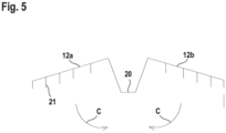
- the embodiment according to the Figures 4a, 4b differs from the design of the Figure 2 in that the tube elements 12a, 12b are connected by film joints 20 ( Figure 5 ).
- the tube elements 12a, 12b with the film joints 20 are formed from only one plastic injection-molded part.
- the film joints 20 are flexible, ie bendable, which is achieved by suitable perforations or material constrictions.
- the tube elements 12a, 12b can be folded in the directions C.
- the tube elements 12a, 12b are folded in accordance with the embodiment according to Figure 2 connected to tube 10.
- the diaphragm 13 with the diaphragm opening 13a is again located in the area of the upper edge of the tube 10, in which the film joints 20 are arranged.
- the field stop 16 with the aperture 16a is again located at the lower edge of the tube 10.
- the optical unit 7 according to the Figures 4a, 4b has as optical element a lens 17 in a lens plane.
- Microstructures 21 are provided on the light traps, which prevent obliquely incident light from reaching the receiver 6.
Landscapes
- Physics & Mathematics (AREA)
- General Physics & Mathematics (AREA)
- Electromagnetism (AREA)
- Engineering & Computer Science (AREA)
- Life Sciences & Earth Sciences (AREA)
- General Life Sciences & Earth Sciences (AREA)
- Geophysics (AREA)
- Computer Networks & Wireless Communication (AREA)
- Radar, Positioning & Navigation (AREA)
- Remote Sensing (AREA)
- Geophysics And Detection Of Objects (AREA)
Claims (10)
- Capteur optique pour la détection d'objets dans une zone de surveillance, comportant au moins un émetteur (4) ayant un axe optique (A) et émettant des faisceaux lumineux, et comportant au moins un récepteur (6) ayant un axe optique (A) et conçu pour recevoir des faisceaux lumineux (3), dans lequel l'émetteur (4) et le récepteur (6) sont chacun équipés d'un tube (10) dont l'axe longitudinal s'étend dans la direction de l'axe optique de l'émetteur (4) ou du récepteur (6), dans lequel le tube (10) est constitué d'une pluralité d'éléments de tube (12a, 12b), qui peuvent être guidés transversalement à l'axe optique du tube (10), et dans lequel les éléments de tube (12a, 12b) forment au moins un plan d'élément dans lequel un élément optique est présent, qui peuvent être guidés transversalement à l'axe optique du tube (10), et dans lequel le tube (10) forme au moins un plan d'élément dans lequel un élément optique est présent, caractérisé en ce que les éléments de tube (12a, 12b) du tube (10) sont reliés par un ou plusieurs joints flexibles, en ce que les éléments de tube (12a, 12b) du tube (10) et les joints flexibles forment une pièce moulée par injection en plastique, en ce que les joints flexibles sont sous la forme de joints de film (20), les joints de film (20) étant formés par des rétrécissements dans le matériau.
- Capteur optique selon la revendication 1, caractérisé par le fait que les éléments tubulaires (12a, 12b) du tube (10) se présentent sous la forme de pièces en plastique moulées par injection.
- Capteur optique selon l'une des revendications 1 ou 2, caractérisé par la présence de moyens de fixation permettant de relier les éléments tubulaires (12a, 12b).
- Capteur optique selon l'une des revendications 1 à 3, caractérisé par le fait que le ou chaque tube (10) comporte des moyens de fixation à un support.
- Capteur optique selon la revendication 4, caractérisé par le fait que les moyens de fixation sont conçus comme des moyens de verrouillage ou de clipsage.
- Capteur optique selon l'une des revendications 4 ou 5, caractérisé par le fait que la base est formée par une carte de circuit imprimé (11) sur laquelle sont disposés plusieurs émetteurs (4) et/ou récepteurs (6).
- Capteur optique selon l'une des revendications 1 à 6, caractérisé par le fait que la paroi intérieure du tube (10) comporte des microstructures (21) formant des pièges à lumière.
- Capteur optique selon l'une des revendications 1 à 7, caractérisé par le fait qu'il s'agit d'un rideau de lumière (1).
- Capteur optique selon la revendication 8, caractérisé par le fait que le rideau lumineux (1) comporte une série d'émetteurs (4), chaque émetteur (4) étant associé à un tube (10), ces tubes (10) formant un ensemble de tubes du côté de l'émetteur, et par le fait que le rideau lumineux (1) comporte une série de récepteurs (6), chaque récepteur (6) étant associé à un tube (10), ces tubes (10) formant un ensemble de tubes du côté du récepteur.
- Capteur optique selon l'une des revendications 1 à 9, caractérisé par le fait qu'il s'agit d'un capteur de sécurité.
Priority Applications (3)
| Application Number | Priority Date | Filing Date | Title |
|---|---|---|---|
| EP22185905.1A EP4220240B1 (fr) | 2022-01-21 | 2022-01-21 | Capteur optique |
| EP22152804.5A EP4215954B1 (fr) | 2022-01-21 | 2022-01-21 | Capteur optique |
| EP22185903.6A EP4220239B1 (fr) | 2022-01-21 | 2022-01-21 | Capteur optique |
Applications Claiming Priority (1)
| Application Number | Priority Date | Filing Date | Title |
|---|---|---|---|
| EP22152804.5A EP4215954B1 (fr) | 2022-01-21 | 2022-01-21 | Capteur optique |
Related Child Applications (4)
| Application Number | Title | Priority Date | Filing Date |
|---|---|---|---|
| EP22185905.1A Division EP4220240B1 (fr) | 2022-01-21 | 2022-01-21 | Capteur optique |
| EP22185905.1A Division-Into EP4220240B1 (fr) | 2022-01-21 | 2022-01-21 | Capteur optique |
| EP22185903.6A Division EP4220239B1 (fr) | 2022-01-21 | 2022-01-21 | Capteur optique |
| EP22185903.6A Division-Into EP4220239B1 (fr) | 2022-01-21 | 2022-01-21 | Capteur optique |
Publications (2)
| Publication Number | Publication Date |
|---|---|
| EP4215954A1 EP4215954A1 (fr) | 2023-07-26 |
| EP4215954B1 true EP4215954B1 (fr) | 2024-08-28 |
Family
ID=80122203
Family Applications (3)
| Application Number | Title | Priority Date | Filing Date |
|---|---|---|---|
| EP22185905.1A Active EP4220240B1 (fr) | 2022-01-21 | 2022-01-21 | Capteur optique |
| EP22185903.6A Active EP4220239B1 (fr) | 2022-01-21 | 2022-01-21 | Capteur optique |
| EP22152804.5A Active EP4215954B1 (fr) | 2022-01-21 | 2022-01-21 | Capteur optique |
Family Applications Before (2)
| Application Number | Title | Priority Date | Filing Date |
|---|---|---|---|
| EP22185905.1A Active EP4220240B1 (fr) | 2022-01-21 | 2022-01-21 | Capteur optique |
| EP22185903.6A Active EP4220239B1 (fr) | 2022-01-21 | 2022-01-21 | Capteur optique |
Country Status (1)
| Country | Link |
|---|---|
| EP (3) | EP4220240B1 (fr) |
Families Citing this family (1)
| Publication number | Priority date | Publication date | Assignee | Title |
|---|---|---|---|---|
| DE102023121562B3 (de) | 2023-08-11 | 2024-08-01 | Sick Ag | Optoelektronischer Sensor und Verfahren zur Herstellung eines optoelektronischen Sensors |
Family Cites Families (11)
| Publication number | Priority date | Publication date | Assignee | Title |
|---|---|---|---|---|
| DE19712828A1 (de) * | 1997-03-26 | 1998-10-15 | Sick Ag | Lichtgitter und Verfahren zu seiner Herstellung |
| DE102004012794A1 (de) * | 2004-03-16 | 2005-11-17 | Sick Ag | Lichtgitter |
| DE102005046359A1 (de) * | 2005-09-28 | 2007-03-29 | Sick Ag | Optoelektronische Anordnung |
| DE202007010493U1 (de) * | 2007-07-27 | 2007-10-31 | Sick Ag | Gehäuse für eine optoelektronische Sensoranordnung |
| DE202007011016U1 (de) * | 2007-08-07 | 2007-10-31 | Leuze Electronic Gmbh & Co Kg | Optischer Sensor |
| DE102009021645B3 (de) * | 2009-05-16 | 2010-11-18 | Sick Ag | Optische Reihenanordnung für Lichtgitter |
| RS56061B1 (sr) * | 2015-01-26 | 2017-10-31 | Schreder | Poboljšanja u ili koja se odnose na nizove sočiva |
| DE102018207294A1 (de) * | 2018-05-09 | 2019-11-14 | Ibeo Automotive Systems GmbH | LIDAR Messsystem und Verfahren zur Montage eines LIDAR Messsystems |
| CN110832345A (zh) * | 2019-04-15 | 2020-02-21 | 深圳市速腾聚创科技有限公司 | 一种激光雷达 |
| US11681019B2 (en) * | 2019-09-18 | 2023-06-20 | Apple Inc. | Optical module with stray light baffle |
| DE202020100208U1 (de) * | 2020-01-16 | 2021-04-19 | Sick Ag | Optoelektronischer Sensor |
-
2022
- 2022-01-21 EP EP22185905.1A patent/EP4220240B1/fr active Active
- 2022-01-21 EP EP22185903.6A patent/EP4220239B1/fr active Active
- 2022-01-21 EP EP22152804.5A patent/EP4215954B1/fr active Active
Also Published As
| Publication number | Publication date |
|---|---|
| EP4220239B1 (fr) | 2024-12-25 |
| EP4220240B1 (fr) | 2024-08-28 |
| EP4220239A1 (fr) | 2023-08-02 |
| EP4220240A1 (fr) | 2023-08-02 |
| EP4215954A1 (fr) | 2023-07-26 |
Similar Documents
| Publication | Publication Date | Title |
|---|---|---|
| DE202005014268U1 (de) | Fahrzeugleuchte mit einer einstückigen Lichtleiter-Blenden-Einheit | |
| AT520400B1 (de) | Beleuchtungs- und/oder signalisierungsvorrichtung für ein kraftfahrzeug | |
| DE102012103310B4 (de) | Beleuchtungsvorrichtung für Fahrzeuge | |
| EP1744096B1 (fr) | Feu pour véhicule automobile | |
| WO2018149741A1 (fr) | Dispositif d'éclairage pour une pièce d'équipement intérieur | |
| DE102011051045A1 (de) | Lichtleitmodul und Leuchte für Fahrzeuge | |
| EP4215954B1 (fr) | Capteur optique | |
| DE102006035842B4 (de) | Fahrzeugleuchte mit einer einstückigen Lichtleiter-Blenden-Einheit | |
| DE112014001749T5 (de) | Lichtleiter-Vorrichtung zur Beleuchtung | |
| EP2023164B1 (fr) | Capteur optique | |
| DE202007010493U1 (de) | Gehäuse für eine optoelektronische Sensoranordnung | |
| EP1907891B1 (fr) | Capteur optique servant a detecter des objets dans une zone de surveillance | |
| DE102019208841A1 (de) | Lötfähiges, insbesondere einstückiges optisches Lichtleitmodul zur Streulichtrauchdetektion sowie Rauchdetektionsblock, Rauchdetektionsmodul und Streulichtrauchmelder | |
| DE102007051681A1 (de) | Optoelektronischer Sensor | |
| EP4215953A1 (fr) | Capteur optique | |
| CH715292A1 (de) | Optikrohling, Optik und Linearleuchte. | |
| DE102013209473B4 (de) | Lichtleiter | |
| CH709341A1 (de) | Vorrichtung und Verfahren zur Erfassung von Objekten in einem Überwachungsbereich. | |
| DE102007055497B4 (de) | Optischer Sensor für ein Kraftfahrzeug | |
| DE102016121913A1 (de) | Mehrstrahllichtschranke | |
| DE102004030777B4 (de) | Gehäuse für einen optischen Sensor | |
| EP2578930B1 (fr) | Module d'éclairage pour lampe extérieure | |
| DE10246945B4 (de) | Fahrzeugleuchte mit Rückstrahlerelement | |
| EP1544037A2 (fr) | Dispositif d'éclairage d'un indicateur de fonction | |
| DE102013222792A1 (de) | Kfz-Beleuchtungseinrichtung |
Legal Events
| Date | Code | Title | Description |
|---|---|---|---|
| PUAI | Public reference made under article 153(3) epc to a published international application that has entered the european phase |
Free format text: ORIGINAL CODE: 0009012 |
|
| STAA | Information on the status of an ep patent application or granted ep patent |
Free format text: STATUS: REQUEST FOR EXAMINATION WAS MADE |
|
| 17P | Request for examination filed |
Effective date: 20220706 |
|
| AK | Designated contracting states |
Kind code of ref document: A1 Designated state(s): AL AT BE BG CH CY CZ DE DK EE ES FI FR GB GR HR HU IE IS IT LI LT LU LV MC MK MT NL NO PL PT RO RS SE SI SK SM TR |
|
| GRAP | Despatch of communication of intention to grant a patent |
Free format text: ORIGINAL CODE: EPIDOSNIGR1 |
|
| STAA | Information on the status of an ep patent application or granted ep patent |
Free format text: STATUS: GRANT OF PATENT IS INTENDED |
|
| GRAS | Grant fee paid |
Free format text: ORIGINAL CODE: EPIDOSNIGR3 |
|
| GRAA | (expected) grant |
Free format text: ORIGINAL CODE: 0009210 |
|
| STAA | Information on the status of an ep patent application or granted ep patent |
Free format text: STATUS: THE PATENT HAS BEEN GRANTED |
|
| INTG | Intention to grant announced |
Effective date: 20240709 |
|
| AK | Designated contracting states |
Kind code of ref document: B1 Designated state(s): AL AT BE BG CH CY CZ DE DK EE ES FI FR GB GR HR HU IE IS IT LI LT LU LV MC MK MT NL NO PL PT RO RS SE SI SK SM TR |
|
| REG | Reference to a national code |
Ref country code: CH Ref legal event code: EP |
|
| REG | Reference to a national code |
Ref country code: DE Ref legal event code: R096 Ref document number: 502022001529 Country of ref document: DE |
|
| REG | Reference to a national code |
Ref country code: IE Ref legal event code: FG4D Free format text: LANGUAGE OF EP DOCUMENT: GERMAN |
|
| P01 | Opt-out of the competence of the unified patent court (upc) registered |
Free format text: CASE NUMBER: APP_51286/2024 Effective date: 20240911 |
|
| REG | Reference to a national code |
Ref country code: LT Ref legal event code: MG9D |
|
| PG25 | Lapsed in a contracting state [announced via postgrant information from national office to epo] |
Ref country code: NO Free format text: LAPSE BECAUSE OF FAILURE TO SUBMIT A TRANSLATION OF THE DESCRIPTION OR TO PAY THE FEE WITHIN THE PRESCRIBED TIME-LIMIT Effective date: 20241128 |
|
| PG25 | Lapsed in a contracting state [announced via postgrant information from national office to epo] |
Ref country code: PT Free format text: LAPSE BECAUSE OF FAILURE TO SUBMIT A TRANSLATION OF THE DESCRIPTION OR TO PAY THE FEE WITHIN THE PRESCRIBED TIME-LIMIT Effective date: 20241230 Ref country code: FI Free format text: LAPSE BECAUSE OF FAILURE TO SUBMIT A TRANSLATION OF THE DESCRIPTION OR TO PAY THE FEE WITHIN THE PRESCRIBED TIME-LIMIT Effective date: 20240828 Ref country code: GR Free format text: LAPSE BECAUSE OF FAILURE TO SUBMIT A TRANSLATION OF THE DESCRIPTION OR TO PAY THE FEE WITHIN THE PRESCRIBED TIME-LIMIT Effective date: 20241129 Ref country code: NL Free format text: LAPSE BECAUSE OF FAILURE TO SUBMIT A TRANSLATION OF THE DESCRIPTION OR TO PAY THE FEE WITHIN THE PRESCRIBED TIME-LIMIT Effective date: 20240828 Ref country code: PL Free format text: LAPSE BECAUSE OF FAILURE TO SUBMIT A TRANSLATION OF THE DESCRIPTION OR TO PAY THE FEE WITHIN THE PRESCRIBED TIME-LIMIT Effective date: 20240828 |
|
| PG25 | Lapsed in a contracting state [announced via postgrant information from national office to epo] |
Ref country code: BG Free format text: LAPSE BECAUSE OF FAILURE TO SUBMIT A TRANSLATION OF THE DESCRIPTION OR TO PAY THE FEE WITHIN THE PRESCRIBED TIME-LIMIT Effective date: 20240828 |
|
| PG25 | Lapsed in a contracting state [announced via postgrant information from national office to epo] |
Ref country code: LV Free format text: LAPSE BECAUSE OF FAILURE TO SUBMIT A TRANSLATION OF THE DESCRIPTION OR TO PAY THE FEE WITHIN THE PRESCRIBED TIME-LIMIT Effective date: 20240828 |
|
| REG | Reference to a national code |
Ref country code: NL Ref legal event code: MP Effective date: 20240828 |
|
| PG25 | Lapsed in a contracting state [announced via postgrant information from national office to epo] |
Ref country code: IS Free format text: LAPSE BECAUSE OF FAILURE TO SUBMIT A TRANSLATION OF THE DESCRIPTION OR TO PAY THE FEE WITHIN THE PRESCRIBED TIME-LIMIT Effective date: 20241228 |
|
| PG25 | Lapsed in a contracting state [announced via postgrant information from national office to epo] |
Ref country code: HR Free format text: LAPSE BECAUSE OF FAILURE TO SUBMIT A TRANSLATION OF THE DESCRIPTION OR TO PAY THE FEE WITHIN THE PRESCRIBED TIME-LIMIT Effective date: 20240828 |
|
| PG25 | Lapsed in a contracting state [announced via postgrant information from national office to epo] |
Ref country code: RS Free format text: LAPSE BECAUSE OF FAILURE TO SUBMIT A TRANSLATION OF THE DESCRIPTION OR TO PAY THE FEE WITHIN THE PRESCRIBED TIME-LIMIT Effective date: 20241128 Ref country code: ES Free format text: LAPSE BECAUSE OF FAILURE TO SUBMIT A TRANSLATION OF THE DESCRIPTION OR TO PAY THE FEE WITHIN THE PRESCRIBED TIME-LIMIT Effective date: 20240828 |
|
| PG25 | Lapsed in a contracting state [announced via postgrant information from national office to epo] |
Ref country code: RS Free format text: LAPSE BECAUSE OF FAILURE TO SUBMIT A TRANSLATION OF THE DESCRIPTION OR TO PAY THE FEE WITHIN THE PRESCRIBED TIME-LIMIT Effective date: 20241128 Ref country code: PT Free format text: LAPSE BECAUSE OF FAILURE TO SUBMIT A TRANSLATION OF THE DESCRIPTION OR TO PAY THE FEE WITHIN THE PRESCRIBED TIME-LIMIT Effective date: 20241230 Ref country code: PL Free format text: LAPSE BECAUSE OF FAILURE TO SUBMIT A TRANSLATION OF THE DESCRIPTION OR TO PAY THE FEE WITHIN THE PRESCRIBED TIME-LIMIT Effective date: 20240828 Ref country code: NO Free format text: LAPSE BECAUSE OF FAILURE TO SUBMIT A TRANSLATION OF THE DESCRIPTION OR TO PAY THE FEE WITHIN THE PRESCRIBED TIME-LIMIT Effective date: 20241128 Ref country code: NL Free format text: LAPSE BECAUSE OF FAILURE TO SUBMIT A TRANSLATION OF THE DESCRIPTION OR TO PAY THE FEE WITHIN THE PRESCRIBED TIME-LIMIT Effective date: 20240828 Ref country code: LV Free format text: LAPSE BECAUSE OF FAILURE TO SUBMIT A TRANSLATION OF THE DESCRIPTION OR TO PAY THE FEE WITHIN THE PRESCRIBED TIME-LIMIT Effective date: 20240828 Ref country code: IS Free format text: LAPSE BECAUSE OF FAILURE TO SUBMIT A TRANSLATION OF THE DESCRIPTION OR TO PAY THE FEE WITHIN THE PRESCRIBED TIME-LIMIT Effective date: 20241228 Ref country code: HR Free format text: LAPSE BECAUSE OF FAILURE TO SUBMIT A TRANSLATION OF THE DESCRIPTION OR TO PAY THE FEE WITHIN THE PRESCRIBED TIME-LIMIT Effective date: 20240828 Ref country code: GR Free format text: LAPSE BECAUSE OF FAILURE TO SUBMIT A TRANSLATION OF THE DESCRIPTION OR TO PAY THE FEE WITHIN THE PRESCRIBED TIME-LIMIT Effective date: 20241129 Ref country code: FI Free format text: LAPSE BECAUSE OF FAILURE TO SUBMIT A TRANSLATION OF THE DESCRIPTION OR TO PAY THE FEE WITHIN THE PRESCRIBED TIME-LIMIT Effective date: 20240828 Ref country code: ES Free format text: LAPSE BECAUSE OF FAILURE TO SUBMIT A TRANSLATION OF THE DESCRIPTION OR TO PAY THE FEE WITHIN THE PRESCRIBED TIME-LIMIT Effective date: 20240828 Ref country code: BG Free format text: LAPSE BECAUSE OF FAILURE TO SUBMIT A TRANSLATION OF THE DESCRIPTION OR TO PAY THE FEE WITHIN THE PRESCRIBED TIME-LIMIT Effective date: 20240828 |
|
| PG25 | Lapsed in a contracting state [announced via postgrant information from national office to epo] |
Ref country code: SM Free format text: LAPSE BECAUSE OF FAILURE TO SUBMIT A TRANSLATION OF THE DESCRIPTION OR TO PAY THE FEE WITHIN THE PRESCRIBED TIME-LIMIT Effective date: 20240828 Ref country code: RO Free format text: LAPSE BECAUSE OF FAILURE TO SUBMIT A TRANSLATION OF THE DESCRIPTION OR TO PAY THE FEE WITHIN THE PRESCRIBED TIME-LIMIT Effective date: 20240828 Ref country code: DK Free format text: LAPSE BECAUSE OF FAILURE TO SUBMIT A TRANSLATION OF THE DESCRIPTION OR TO PAY THE FEE WITHIN THE PRESCRIBED TIME-LIMIT Effective date: 20240828 |
|
| PG25 | Lapsed in a contracting state [announced via postgrant information from national office to epo] |
Ref country code: EE Free format text: LAPSE BECAUSE OF FAILURE TO SUBMIT A TRANSLATION OF THE DESCRIPTION OR TO PAY THE FEE WITHIN THE PRESCRIBED TIME-LIMIT Effective date: 20240828 |
|
| PG25 | Lapsed in a contracting state [announced via postgrant information from national office to epo] |
Ref country code: CZ Free format text: LAPSE BECAUSE OF FAILURE TO SUBMIT A TRANSLATION OF THE DESCRIPTION OR TO PAY THE FEE WITHIN THE PRESCRIBED TIME-LIMIT Effective date: 20240828 |
|
| PG25 | Lapsed in a contracting state [announced via postgrant information from national office to epo] |
Ref country code: SK Free format text: LAPSE BECAUSE OF FAILURE TO SUBMIT A TRANSLATION OF THE DESCRIPTION OR TO PAY THE FEE WITHIN THE PRESCRIBED TIME-LIMIT Effective date: 20240828 Ref country code: IT Free format text: LAPSE BECAUSE OF FAILURE TO SUBMIT A TRANSLATION OF THE DESCRIPTION OR TO PAY THE FEE WITHIN THE PRESCRIBED TIME-LIMIT Effective date: 20240828 |
|
| REG | Reference to a national code |
Ref country code: DE Ref legal event code: R097 Ref document number: 502022001529 Country of ref document: DE |
|
| PLBE | No opposition filed within time limit |
Free format text: ORIGINAL CODE: 0009261 |
|
| STAA | Information on the status of an ep patent application or granted ep patent |
Free format text: STATUS: NO OPPOSITION FILED WITHIN TIME LIMIT |
|
| 26N | No opposition filed |
Effective date: 20250530 |
|
| REG | Reference to a national code |
Ref country code: CH Ref legal event code: PL |
|
| PG25 | Lapsed in a contracting state [announced via postgrant information from national office to epo] |
Ref country code: SE Free format text: LAPSE BECAUSE OF FAILURE TO SUBMIT A TRANSLATION OF THE DESCRIPTION OR TO PAY THE FEE WITHIN THE PRESCRIBED TIME-LIMIT Effective date: 20240828 |
|
| PG25 | Lapsed in a contracting state [announced via postgrant information from national office to epo] |
Ref country code: LU Free format text: LAPSE BECAUSE OF NON-PAYMENT OF DUE FEES Effective date: 20250121 Ref country code: MC Free format text: LAPSE BECAUSE OF FAILURE TO SUBMIT A TRANSLATION OF THE DESCRIPTION OR TO PAY THE FEE WITHIN THE PRESCRIBED TIME-LIMIT Effective date: 20240828 |
|
| PG25 | Lapsed in a contracting state [announced via postgrant information from national office to epo] |
Ref country code: BE Free format text: LAPSE BECAUSE OF NON-PAYMENT OF DUE FEES Effective date: 20250131 |
|
| PG25 | Lapsed in a contracting state [announced via postgrant information from national office to epo] |
Ref country code: FR Free format text: LAPSE BECAUSE OF NON-PAYMENT OF DUE FEES Effective date: 20250131 |
|
| PG25 | Lapsed in a contracting state [announced via postgrant information from national office to epo] |
Ref country code: CH Free format text: LAPSE BECAUSE OF NON-PAYMENT OF DUE FEES Effective date: 20250131 |
|
| REG | Reference to a national code |
Ref country code: BE Ref legal event code: MM Effective date: 20250131 |
|
| PG25 | Lapsed in a contracting state [announced via postgrant information from national office to epo] |
Ref country code: IE Free format text: LAPSE BECAUSE OF NON-PAYMENT OF DUE FEES Effective date: 20250121 |
|
| PGFP | Annual fee paid to national office [announced via postgrant information from national office to epo] |
Ref country code: DE Payment date: 20260121 Year of fee payment: 5 |
|
| PGFP | Annual fee paid to national office [announced via postgrant information from national office to epo] |
Ref country code: AT Payment date: 20260301 Year of fee payment: 5 |