EP4215971A1 - Procédé pour enregistrer une image acquise au moyen de la microscopie de localisation de molécule unique - Google Patents
Procédé pour enregistrer une image acquise au moyen de la microscopie de localisation de molécule unique Download PDFInfo
- Publication number
- EP4215971A1 EP4215971A1 EP22152746.8A EP22152746A EP4215971A1 EP 4215971 A1 EP4215971 A1 EP 4215971A1 EP 22152746 A EP22152746 A EP 22152746A EP 4215971 A1 EP4215971 A1 EP 4215971A1
- Authority
- EP
- European Patent Office
- Prior art keywords
- image
- interest
- local regions
- regions
- files
- Prior art date
- Legal status (The legal status is an assumption and is not a legal conclusion. Google has not performed a legal analysis and makes no representation as to the accuracy of the status listed.)
- Withdrawn
Links
Images

Classifications
-
- G—PHYSICS
- G01—MEASURING; TESTING
- G01N—INVESTIGATING OR ANALYSING MATERIALS BY DETERMINING THEIR CHEMICAL OR PHYSICAL PROPERTIES
- G01N21/00—Investigating or analysing materials by the use of optical means, i.e. using sub-millimetre waves, infrared, visible or ultraviolet light
- G01N21/62—Systems in which the material investigated is excited whereby it emits light or causes a change in wavelength of the incident light
- G01N21/63—Systems in which the material investigated is excited whereby it emits light or causes a change in wavelength of the incident light optically excited
- G01N21/64—Fluorescence; Phosphorescence
- G01N21/645—Specially adapted constructive features of fluorimeters
- G01N21/6456—Spatial resolved fluorescence measurements; Imaging
- G01N21/6458—Fluorescence microscopy
-
- G—PHYSICS
- G06—COMPUTING OR CALCULATING; COUNTING
- G06T—IMAGE DATA PROCESSING OR GENERATION, IN GENERAL
- G06T1/00—General purpose image data processing
- G06T1/0007—Image acquisition
-
- G—PHYSICS
- G02—OPTICS
- G02B—OPTICAL ELEMENTS, SYSTEMS OR APPARATUS
- G02B21/00—Microscopes
- G02B21/0004—Microscopes specially adapted for specific applications
- G02B21/002—Scanning microscopes
- G02B21/0024—Confocal scanning microscopes (CSOMs) or confocal "macroscopes"; Accessories which are not restricted to use with CSOMs, e.g. sample holders
- G02B21/0052—Optical details of the image generation
- G02B21/0076—Optical details of the image generation arrangements using fluorescence or luminescence
-
- G—PHYSICS
- G02—OPTICS
- G02B—OPTICAL ELEMENTS, SYSTEMS OR APPARATUS
- G02B21/00—Microscopes
- G02B21/36—Microscopes arranged for photographic purposes or projection purposes or digital imaging or video purposes including associated control and data processing arrangements
- G02B21/365—Control or image processing arrangements for digital or video microscopes
- G02B21/367—Control or image processing arrangements for digital or video microscopes providing an output produced by processing a plurality of individual source images, e.g. image tiling, montage, composite images, depth sectioning, image comparison
-
- G—PHYSICS
- G06—COMPUTING OR CALCULATING; COUNTING
- G06V—IMAGE OR VIDEO RECOGNITION OR UNDERSTANDING
- G06V10/00—Arrangements for image or video recognition or understanding
- G06V10/10—Image acquisition
- G06V10/12—Details of acquisition arrangements; Constructional details thereof
- G06V10/14—Optical characteristics of the device performing the acquisition or on the illumination arrangements
- G06V10/143—Sensing or illuminating at different wavelengths
-
- G—PHYSICS
- G06—COMPUTING OR CALCULATING; COUNTING
- G06V—IMAGE OR VIDEO RECOGNITION OR UNDERSTANDING
- G06V10/00—Arrangements for image or video recognition or understanding
- G06V10/20—Image preprocessing
- G06V10/22—Image preprocessing by selection of a specific region containing or referencing a pattern; Locating or processing of specific regions to guide the detection or recognition
- G06V10/23—Image preprocessing by selection of a specific region containing or referencing a pattern; Locating or processing of specific regions to guide the detection or recognition based on positionally close patterns or neighbourhood relationships
-
- G—PHYSICS
- G06—COMPUTING OR CALCULATING; COUNTING
- G06V—IMAGE OR VIDEO RECOGNITION OR UNDERSTANDING
- G06V10/00—Arrangements for image or video recognition or understanding
- G06V10/20—Image preprocessing
- G06V10/25—Determination of region of interest [ROI] or a volume of interest [VOI]
-
- G—PHYSICS
- G06—COMPUTING OR CALCULATING; COUNTING
- G06V—IMAGE OR VIDEO RECOGNITION OR UNDERSTANDING
- G06V20/00—Scenes; Scene-specific elements
- G06V20/60—Type of objects
- G06V20/69—Microscopic objects, e.g. biological cells or cellular parts
- G06V20/693—Acquisition
-
- G—PHYSICS
- G06—COMPUTING OR CALCULATING; COUNTING
- G06V—IMAGE OR VIDEO RECOGNITION OR UNDERSTANDING
- G06V20/00—Scenes; Scene-specific elements
- G06V20/60—Type of objects
- G06V20/69—Microscopic objects, e.g. biological cells or cellular parts
- G06V20/695—Preprocessing, e.g. image segmentation
-
- G—PHYSICS
- G06—COMPUTING OR CALCULATING; COUNTING
- G06V—IMAGE OR VIDEO RECOGNITION OR UNDERSTANDING
- G06V2201/00—Indexing scheme relating to image or video recognition or understanding
- G06V2201/10—Recognition assisted with metadata
Definitions
- the present invention relates to a method and apparatus for saving an image acquired using single molecule localization microscopy.
- Single molecule localization microscopy is based on the delayed stochastic emission of molecules in order to achieve the emission of single fluorescent molecules.
- a sample containing fluorescent molecules is illuminated using an irradiance tuned in such a way that, on average, at each time there is only one active (i.e. emitting) molecule in a focal volume of an observing microscope.
- each fluorescent molecule is labelled with SMLM fluorophores so that the fluorescent molecules undergo reversible transitions between ON and OFF emission states (i.e. blink) when being under illumination.
- Images acquired by SMLM present image spots called point spread functions (PSFs), and each spot represents the image of a fluorescent molecule.
- PSFs point spread functions
- regions of interest will only include regions comprising fluorescent molecules. Additionally, since single fluorescent molecules blink under illumination, regions of an acquired image may present no PSF since some of the fluorescent molecules are "OFF" when acquiring the image.
- the present invention relates to the determination of regions of interest for each image acquired during an SMLM experiment, the regions of interest comprising the PSFs. From the determined regions of interest, it is possible to only store the pixels corresponding to the regions of interest, and therefore excluding the regions presenting no fluorescent molecules.
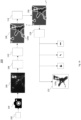
- FIG 1a and Figure 1b are schematic diagrams of an apparatus 100 for saving an image of a sample 102 acquired using single molecule localization microscopy (SMLM), according to two examples.
- SMLM single molecule localization microscopy
- the sample 102 may be made of, for example, cell (such as neurons) or tissue samples comprising molecules which have been fluorescently labeled.
- the fluorescent molecules may have been labelled using SMLM fluorophores such as photoswitchable, photoactivable, photoconvertible, spontaneously blinking or temporarily blinking fluorophores. That way, once labelled, the fluorescent molecules undergo reversible transitions between ON and OFF emission states (i.e. blink) when being under illumination.
- samples comprising fluorescent molecules have a heterogeneous density of fluorescent molecules. Therefore, regions of the sample 102 may have a high density of fluorescent molecules while other regions may have a low density of fluorescent molecules. Additionally or alternatively, other regions may have no fluorescent molecules.
- the apparatus 100 comprises an image acquisition unit 104, a detection unit 108, a determination 110, a calculation unit 114 and a file unit 118.
- Each of the detection unit 108, determination unit 110, calculation unit 114 and file unit 118 may be implemented using hardware, software, and/or a combination thereof.
- hardware devices may be implemented using processing circuity such as, but not limited to, a processor, Central Processing Unit (CPU), a controller, an arithmetic logic unit (ALU), a digital signal processor, a microcomputer, a field programmable gate array (FPGA), a System-on-Chip (SoC), a programmable logic unit, a microprocessor, or any other device capable of responding to and executing instructions in a defined manner.
- Software may include a computer program, program code, instructions, or some combination thereof, for independently or collectively instructing or configuring a hardware device to operate as desired.
- the computer program and/or program code may include program or computer-readable instructions, software components, software modules, data files, data structures, and/or the like, capable of being implemented by one or more hardware devices, such as one or more of the hardware devices mentioned above.
- a hardware device is a computer processing device (e.g. CPU, a controller, an ALU, a digital signal processor, a microcomputer, a microprocessor, etc.)
- the computer processing device may be configured to carry out program code by performing arithmetical, logical, and input/output operations, according to the program code.
- Each unit may also include one or more storage devices.
- the one or more storage devices may be tangible or non-transitory computer-readable storage media, such as random access memory (RAM), read only memory (ROM), a permanent mass storage device (such as a disk drive), solid state (e.g., NAND flash) device, and/or any other like data storage mechanism capable of storing and recording data.
- the one or more storage devices may be configured to store computer programs, program code, instructions, or some combination thereof, for one or more operating systems and/or for implementing the example embodiments described herein.
- the computer programs, program code, instructions, or some combination thereof may also be loaded from a separate computer readable storage medium into the one or more storage devices and/or one or more computer processing devices using a drive mechanism.
- Such separate computer readable storage medium may include a Universal Serial Bus (USB) flash drive, a memory stick, a Blu-ray/DVD/CD-ROM drive, a memory card, and/or other like computer readable storage media.
- USB Universal Serial Bus
- two or more units of the detection unit 108, determination unit 110, calculation unit 114 and file unit 118 may be implemented by the same hardware and/or software.
- all of the detection unit 108, determination unit 110, calculation unit 114 and file unit 118 may be implemented by a single computer storage medium capable of providing instructions to each unit to carry out functions described below.
- the image acquisition unit 104 is configured to acquire an image 106 of the sample 102 while the sample 102 is under illumination.
- the acquisition unit 104 may be, for example a camera, such as a sCMOS camera.
- a scanning unit (not shown) comprising a laser emitting a first wavelength which corresponds to the excitation wavelength of the fluorophores which have been used to label the molecules comprised in the sample 102.
- the laser may be a diode-pumped solid-state laser emitting at 638 nm.
- the scanning unit may be, for example, an Adaptable Scanning for Tunable Excitation Regions (ASTER) system disclosed in Mau et. al 1 .
- the image 106 acquired while being under illumination is acquired by the image acquisition unit 104 at a second wavelength which corresponds to the emission wavelength of the fluorophores which have been used to label the molecules of the sample 102.
- the first wavelength and the second wavelength may be the same.
- Figure 1a and Figure 1b show an example of the image 106 which presents spots, or point spread functions (PSFs), and each PSF represent a single fluorescent molecule.
- the density of PSFs of the image 106 is not uniform as, in this example, the sample 102 presents a heterogeneous density of fluorescent molecules.
- the sample 102, and therefore, the image 106 presents high density regions (i.e. regions showing a high density of spots), low density regions (i.e. regions showing a low density of spots), mid density regions (i.e. regions showing a mid density of spots) and regions with no fluorescent molecules (i.e. dark regions).
- the detection unit 108 receives the image 106 from the image acquisition unit 104 and is configured to detect the plurality of spots in the image 106, each spot representing one single fluorescent molecule of the single fluorescent molecules comprised in the sample 102.
- the detection unit 108 may be implemented using an algorithm which analyses the pixels of the images 106 and detects contrast between the pixels, i.e. the variations in intensity of the pixels. In particular, the algorithm detects contours of high contrast which represents the edges of each spot.
- the detection unit 108 can then define a mapping of the spots on the image 106, which indicates the position of each spot based on the detected contrast. In an example, the method described in Bourg et. al 2 is used to detect the plurality of spots in the image 106.
- each spot can be modelled as a dipolar emitter radiating in the far field.
- each spot has a non-propagative near-field component which depends on a surrounding refractive index n m .
- n m refractive index
- the transmitted light follows the Snell-Descartes law of refraction.
- the determination unit 110 is configured to define local regions of interest 120a, 120b comprising the spots in the image 106.
- the determination unit 110 receives the mapping of the spots from the detection unit 108.
- the determination unit 110 defines the local regions of interest 120a, 120b which are optimized to include all the regions of the image 106 which comprise the PSFs while excluding the regions which do not comprise PSFs.
- the local regions of interest 120a are ellipses which are defined in a way which minimizes the overall surface of the local regions of interest 120a.
- the local regions of interest 120b may be polygons.
- the polygons may be defined so that each polygon comprises the highest possible number of PSFs and the smallest possible surface of the region which comprises no PSF.
- the local regions of interest 120b may include at least one ellipse and one polygon.
- the local regions of interest 120b may comprise only one PSF.
- the calculation unit 114 is configured to determine metadata defining each of the local regions of interest 120a, 120b.
- the metadata may define the shape of each local region of interest 120a, 120b (e.g. an ellipse or a polygon) and/or coordinates defining a position of the local regions of interest 120a, 120b in the image 106.
- the calculation unit 114 may define axes x, y corresponding to two of the edges of the image 106 on which the local regions of interest 120a, 120b are defined.
- the calculation unit 114 may define coordinates in the x-y plane corresponding to the center, a vertex and a co-vertex of each ellipse 120a.
- the calculation unit 114 may define coordinates in the x-y plane corresponding to each vertex of each polygon 120b.
- the file unit 118 creates image files 122 comprising image data of the local regions of interest 120a, 120b and the determined metadata. For example, as seen in Figure 1a , the file unit 118 creates 19 image files 122, each image file 122 comprising image data of each of the 19 ellipses 120a defined by the determination unit 110. Alternatively, as seen in Figure 1b , the file unit 118 creates four image files 122, each image file 122 comprising image data of each of the four polygons defined in by the determination unit 110.
- the file unit 118 saves the image files 122.
- the file unit 118 saves the image files 122 comprising image data of the local regions of interest 120a, 120b and their corresponding metadata in a file which may be compressed.
- the file may be stored in a local storage space and/or a cloud storage service.
- the process performed by the apparatus 100 described above may be repeated multiple times. For example, the process may be performed thousands or tens of thousands of times.
- a further image is acquired by the image acquisition unit 104, further PSFs are detected in the further image by the detection unit 108, further local regions of interest are determined by the determination unit 110, further metadata defining e the further local regions of interest are determined by the calculation unit 114, and further image files comprising image data of the further local regions of interest and metadata are created and saved by the file unit 118.
- the file unit 118 may create a final file which includes all the image files (i.e. the image files 122 and the further image files).
- the final file may be compressed and/or saved in a local storage space and/or a cloud storage service.
- the final file may be saved in database and the metadata may be used for searching for a particular region of interest 120a, 120b in the database.
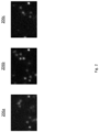
- the process performed by the apparatus 100 described above may be repeated at least three times and a first image 206a, a second image 206b and a third image 206b may be acquired by the image acquiring unit 104, and the determination unit 110 may determine a background of the second image 206b.
- the first image 206a, second image 206b and third image 206b do not present the same PSFs since they were acquired at different times.
- the determination unit 110 may determine the background of the second image 206b by comparing the second image 206b to the image acquired before (i.e.
- the background corresponds to the regions of the image which do not comprise PSFs.
- a dark region i.e. a region which does not show fluorescent molecules, may comprise PSFs at another time. Therefore, in order to subtract the background, several images must be considered.
- the determination unit 110 may combine the regions of interest 120a, 120b in each of the first image 206a, a second image 206b and a third image 206b, and determine the background which corresponds to the remaining regions of the second image 206b.
- the file unit 118 may create a background-free image file which comprises image data of the second image 206b from which the background has been subtracted.
- the file unit 118 may save the image file.
- SMLM single tens of thousands of images are used to obtain a final super-resolved image with a high spatial resolution. Therefore, tens of thousands of images may be used to remove the background of an image acquired in an SMLM experiment.
- median temporal filtering may be used to remove the background of an image acquired in an SMLM experiment, as described in Hoogendoorn et. al 3 .
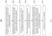
- Figure 3 is a flow diagram depicting a method 300 for saving an image 106 acquired using single molecule localization microscopy.
- the method 300 may be implemented by the apparatus 100 described above with reference to Figure 1a and Figure 1b .
- an image 106 of a sample 102 comprising a plurality of single fluorescent molecules is acquired using single molecule localization microscopy.
- the image 106 is acquired with a camera which is part of an Adaptable Scanning for Tunable Excitation Regions (ASTER) system.
- ASTER Adaptable Scanning for Tunable Excitation Regions
- a plurality of spots are detected in the image 106, each spot representing one single fluorescent molecule of the plurality of single fluorescent molecules.
- the spots are detected with an algorithm which analyses contrast in the image 106.
- one or more local regions of interest 120a, 120b comprising the detected plurality of spots are determined.
- the regions of interest 120a, 120b may have a shape which is polygonal shape and/or an elliptical shape.
- the regions of interest 120a, 120b may comprise only one spot.
- the metadata may include the coordinates of the center and a vertex and a co-vertex of an ellipse for a local region of interest 120a which has an elliptical shape
- the metadata include the coordinates of the vertices of a polygon for a local region of interest 120b which has a polygonal shape.
- one or more image files 122 are created, wherein each of the one or more image files 122 comprises image data of each of the one or more local regions of interest 120a, 120b and the determined metadata defining each of the one or more local regions of interest 120a, 120b.
- the one or more image files are saved.
- the image files 122 may be saved in a cloud storage service.
- the method 300 may be repeated multiple times. Each time the method is repeated a further image 106 of the sample 102 is acquired, a further plurality of spots is detected in the further image 106, further one or more local regions of interest 120a, 120b comprising the further detected plurality of spots are detected, further metadata defining each of the further one or more the local regions of interest 120a are determined, 120b and further one or more image files 122 are created. Each of the further one or more image files comprises further image data of each of further one or more local regions of interest and further metadata defining each of the further one or more local regions of interest. A final file comprising the image data of each of the one or more image files and the further image data of the further one or more image files and saved, for example in a cloud storage service.
- the method 300 may be performed three times.
- a first image 206a, a second image 206b and a third image 206c may be acquired at block 302, and the steps described above are repeated for each of the first image 206a, second image 206b and third image 206c.
- Each of the first image 206a, second image 206b and third image 206c present a background, which represents a region of the images which does not comprise local regions of interest.
- the background of the second image may be determined based on the regions of interest 120a, 120b determined for each of the first image 206a, the second image 206b and the third image 206c.
- the background of the second image 206b may be subtracted and a background-free image file comprising image data of the second image 206b without the background may be created.
Landscapes
- Engineering & Computer Science (AREA)
- Physics & Mathematics (AREA)
- General Physics & Mathematics (AREA)
- Multimedia (AREA)
- Theoretical Computer Science (AREA)
- Health & Medical Sciences (AREA)
- Life Sciences & Earth Sciences (AREA)
- General Health & Medical Sciences (AREA)
- Chemical & Material Sciences (AREA)
- Analytical Chemistry (AREA)
- Molecular Biology (AREA)
- Biomedical Technology (AREA)
- Optics & Photonics (AREA)
- Computer Vision & Pattern Recognition (AREA)
- Nuclear Medicine, Radiotherapy & Molecular Imaging (AREA)
- Biochemistry (AREA)
- Immunology (AREA)
- Pathology (AREA)
- Microscoopes, Condenser (AREA)
- Investigating, Analyzing Materials By Fluorescence Or Luminescence (AREA)
- Image Analysis (AREA)
Priority Applications (8)
| Application Number | Priority Date | Filing Date | Title |
|---|---|---|---|
| EP22152746.8A EP4215971A1 (fr) | 2022-01-21 | 2022-01-21 | Procédé pour enregistrer une image acquise au moyen de la microscopie de localisation de molécule unique |
| AU2023209120A AU2023209120A1 (en) | 2022-01-21 | 2023-01-17 | Method for saving an image acquired using single molecule localization microscopy |
| EP23701031.9A EP4466562A1 (fr) | 2022-01-21 | 2023-01-17 | Procédé de sauvegarde d'une image acquise à l'aide d'une microscopie de localisation à molécule unique |
| PCT/EP2023/050920 WO2023139036A1 (fr) | 2022-01-21 | 2023-01-17 | Procédé de sauvegarde d'une image acquise à l'aide d'une microscopie de localisation à molécule unique |
| JP2024541818A JP2025502213A (ja) | 2022-01-21 | 2023-01-17 | 単分子局在顕微鏡法を用いて取得した画像を保存する方法 |
| IL314255A IL314255A (en) | 2022-01-21 | 2023-01-17 | Method for saving an image acquired using single molecule localization microscopy |
| CA3248711A CA3248711A1 (fr) | 2022-01-21 | 2023-01-17 | Procédé de sauvegarde d’une image acquise à l’aide d’une microscopie de localisation à molécule unique |
| US18/730,329 US20250086745A1 (en) | 2022-01-21 | 2023-01-17 | Method for saving an image acquired using single molecule localization microscopy |
Applications Claiming Priority (1)
| Application Number | Priority Date | Filing Date | Title |
|---|---|---|---|
| EP22152746.8A EP4215971A1 (fr) | 2022-01-21 | 2022-01-21 | Procédé pour enregistrer une image acquise au moyen de la microscopie de localisation de molécule unique |
Publications (1)
| Publication Number | Publication Date |
|---|---|
| EP4215971A1 true EP4215971A1 (fr) | 2023-07-26 |
Family
ID=80122023
Family Applications (2)
| Application Number | Title | Priority Date | Filing Date |
|---|---|---|---|
| EP22152746.8A Withdrawn EP4215971A1 (fr) | 2022-01-21 | 2022-01-21 | Procédé pour enregistrer une image acquise au moyen de la microscopie de localisation de molécule unique |
| EP23701031.9A Pending EP4466562A1 (fr) | 2022-01-21 | 2023-01-17 | Procédé de sauvegarde d'une image acquise à l'aide d'une microscopie de localisation à molécule unique |
Family Applications After (1)
| Application Number | Title | Priority Date | Filing Date |
|---|---|---|---|
| EP23701031.9A Pending EP4466562A1 (fr) | 2022-01-21 | 2023-01-17 | Procédé de sauvegarde d'une image acquise à l'aide d'une microscopie de localisation à molécule unique |
Country Status (7)
| Country | Link |
|---|---|
| US (1) | US20250086745A1 (fr) |
| EP (2) | EP4215971A1 (fr) |
| JP (1) | JP2025502213A (fr) |
| AU (1) | AU2023209120A1 (fr) |
| CA (1) | CA3248711A1 (fr) |
| IL (1) | IL314255A (fr) |
| WO (1) | WO2023139036A1 (fr) |
Citations (3)
| Publication number | Priority date | Publication date | Assignee | Title |
|---|---|---|---|---|
| US20020081014A1 (en) * | 1997-05-14 | 2002-06-27 | Applied Imaging Corporation | Identification of objects of interest using multiple illumination schemes and finding overlap of features in corresponding multiple images |
| US20110175995A1 (en) * | 2005-06-13 | 2011-07-21 | Tripath Imaging, Inc. | System and method for re-locating an object in a sample on a slide with a microscope imaging device |
| EP3660490A1 (fr) * | 2018-11-30 | 2020-06-03 | Fundació Institut de Ciències Fotòniques | Imagerie multicolore |
Family Cites Families (3)
| Publication number | Priority date | Publication date | Assignee | Title |
|---|---|---|---|---|
| WO2009115108A1 (fr) * | 2008-03-19 | 2009-09-24 | Ruprecht-Karls-Universität Heidelberg | Procédé et dispositif servant à localiser des molécules monochromes en microscopie fluorescente |
| US10319085B2 (en) * | 2015-02-16 | 2019-06-11 | Samsung Electronics Co., Ltd. | Metadata-based image processing method and apparatus |
| AU2020385015A1 (en) * | 2019-11-17 | 2022-06-09 | Berkeley Lights, Inc. | Systems and methods for analyses of biological samples |
-
2022
- 2022-01-21 EP EP22152746.8A patent/EP4215971A1/fr not_active Withdrawn
-
2023
- 2023-01-17 AU AU2023209120A patent/AU2023209120A1/en active Pending
- 2023-01-17 IL IL314255A patent/IL314255A/en unknown
- 2023-01-17 US US18/730,329 patent/US20250086745A1/en active Pending
- 2023-01-17 CA CA3248711A patent/CA3248711A1/fr active Pending
- 2023-01-17 WO PCT/EP2023/050920 patent/WO2023139036A1/fr not_active Ceased
- 2023-01-17 JP JP2024541818A patent/JP2025502213A/ja active Pending
- 2023-01-17 EP EP23701031.9A patent/EP4466562A1/fr active Pending
Patent Citations (3)
| Publication number | Priority date | Publication date | Assignee | Title |
|---|---|---|---|---|
| US20020081014A1 (en) * | 1997-05-14 | 2002-06-27 | Applied Imaging Corporation | Identification of objects of interest using multiple illumination schemes and finding overlap of features in corresponding multiple images |
| US20110175995A1 (en) * | 2005-06-13 | 2011-07-21 | Tripath Imaging, Inc. | System and method for re-locating an object in a sample on a slide with a microscope imaging device |
| EP3660490A1 (fr) * | 2018-11-30 | 2020-06-03 | Fundació Institut de Ciències Fotòniques | Imagerie multicolore |
Non-Patent Citations (3)
| Title |
|---|
| BOURG: "Direct optical nanoscopy with axially localized detection", NATURE PHOTONICS, vol. 9, 2015, pages 587 |
| HOOGENDOORN: "The fidelity of stochastic single-molecule super-resolution reconstructions critically depends upon robust background estimation", SCIENTIFIC REPORTS, vol. 4, 2014, pages 3854 |
| MAU: "Fast widefield scan provides tunable and uniform illumination optimizing super-resolution microscopy on large fields", NATURE COMMUNICATIONS, vol. 12, 2021, pages 3077 |
Also Published As
| Publication number | Publication date |
|---|---|
| JP2025502213A (ja) | 2025-01-24 |
| US20250086745A1 (en) | 2025-03-13 |
| CA3248711A1 (fr) | 2023-07-27 |
| IL314255A (en) | 2024-09-01 |
| WO2023139036A1 (fr) | 2023-07-27 |
| EP4466562A1 (fr) | 2024-11-27 |
| AU2023209120A1 (en) | 2024-07-25 |
Similar Documents
| Publication | Publication Date | Title |
|---|---|---|
| EP3051276B2 (fr) | Dispositif d'analyse, dispositif de microscope, procédé d'analyse, et programme | |
| US9996924B2 (en) | Systems and methods for spectral unmixing of microscopic images using pixel grouping | |
| CN111656246B (zh) | 用于定位显微的方法和系统、计算机可读存储介质 | |
| US10169878B2 (en) | System and method for segmentation of three-dimensional microscope images | |
| Schmied et al. | Open-source solutions for SPIMage processing | |
| Bashar et al. | Automatic extraction of nuclei centroids of mouse embryonic cells from fluorescence microscopy images | |
| US10591402B2 (en) | Image processing apparatus, image processing method, and image processing program | |
| Nino et al. | FOCAL3D: A 3-dimensional clustering package for single-molecule localization microscopy | |
| EP4123354A1 (fr) | Dispositif d'observation d'échantillon et procédé d'observation d'échantillon | |
| EP4215971A1 (fr) | Procédé pour enregistrer une image acquise au moyen de la microscopie de localisation de molécule unique | |
| Cha et al. | Reassignment of scattered emission photons in multifocal multiphoton microscopy | |
| FR2743416A1 (fr) | Procede de comparaison de douilles projectiles et dispositif | |
| US12579657B2 (en) | Imaging device and method | |
| Shimoni et al. | Normalized polarization ratios for the analysis of cell polarity | |
| JP2016067280A (ja) | 画像処理方法、制御プログラム、記録媒体および画像処理装置 | |
| Feng et al. | MSDenoiser: Muti-step adaptive denoising framework for super-resolution image from single molecule localization microscopy | |
| US9589172B1 (en) | Systems and methods for interactive image analysis of digital pathology images | |
| US20070124085A1 (en) | Method of processing a biological image | |
| Manoilov et al. | Algorithms for Image Processing in a Nanofor SPS DNA Sequencer | |
| CN110749606A (zh) | 一种基于光学元件的激光损伤检测方法及系统 | |
| US20250356522A1 (en) | Immunoassay | |
| US20240378719A1 (en) | Method and system to obtain sufficient cytology image in cytopathology | |
| US20240378723A1 (en) | Methods and systems for processing medical images | |
| CN118570045A (zh) | 荧光显微镜中基于寿命的解混的处理器 | |
| Ovesný | Computational methods in single molecule localization microscopy |
Legal Events
| Date | Code | Title | Description |
|---|---|---|---|
| PUAI | Public reference made under article 153(3) epc to a published international application that has entered the european phase |
Free format text: ORIGINAL CODE: 0009012 |
|
| STAA | Information on the status of an ep patent application or granted ep patent |
Free format text: STATUS: THE APPLICATION HAS BEEN PUBLISHED |
|
| AK | Designated contracting states |
Kind code of ref document: A1 Designated state(s): AL AT BE BG CH CY CZ DE DK EE ES FI FR GB GR HR HU IE IS IT LI LT LU LV MC MK MT NL NO PL PT RO RS SE SI SK SM TR |
|
| STAA | Information on the status of an ep patent application or granted ep patent |
Free format text: STATUS: REQUEST FOR EXAMINATION WAS MADE |
|
| 17P | Request for examination filed |
Effective date: 20240122 |
|
| RBV | Designated contracting states (corrected) |
Designated state(s): AL AT BE BG CH CY CZ DE DK EE ES FI FR GB GR HR HU IE IS IT LI LT LU LV MC MK MT NL NO PL PT RO RS SE SI SK SM TR |
|
| STAA | Information on the status of an ep patent application or granted ep patent |
Free format text: STATUS: EXAMINATION IS IN PROGRESS |
|
| 17Q | First examination report despatched |
Effective date: 20250527 |
|
| STAA | Information on the status of an ep patent application or granted ep patent |
Free format text: STATUS: THE APPLICATION IS DEEMED TO BE WITHDRAWN |
|
| 18D | Application deemed to be withdrawn |
Effective date: 20250930 |