EP4216412A1 - Dispositif d'enroulement d'aiguille et procédé d'enroulement d'aiguille pour produire des enroulements polaires d'un rotor fsm - Google Patents
Dispositif d'enroulement d'aiguille et procédé d'enroulement d'aiguille pour produire des enroulements polaires d'un rotor fsm Download PDFInfo
- Publication number
- EP4216412A1 EP4216412A1 EP22197764.8A EP22197764A EP4216412A1 EP 4216412 A1 EP4216412 A1 EP 4216412A1 EP 22197764 A EP22197764 A EP 22197764A EP 4216412 A1 EP4216412 A1 EP 4216412A1
- Authority
- EP
- European Patent Office
- Prior art keywords
- winding
- rotor body
- needle
- poles
- rotor
- Prior art date
- Legal status (The legal status is an assumption and is not a legal conclusion. Google has not performed a legal analysis and makes no representation as to the accuracy of the status listed.)
- Pending
Links
Images

Classifications
-
- H—ELECTRICITY
- H02—GENERATION; CONVERSION OR DISTRIBUTION OF ELECTRIC POWER
- H02K—DYNAMO-ELECTRIC MACHINES
- H02K15/00—Processes or apparatus specially adapted for manufacturing, assembling, maintaining or repairing of dynamo-electric machines
- H02K15/08—Forming windings by laying conductors into or around core parts
- H02K15/095—Forming windings by laying conductors into or around core parts by laying conductors around salient poles
-
- H—ELECTRICITY
- H02—GENERATION; CONVERSION OR DISTRIBUTION OF ELECTRIC POWER
- H02K—DYNAMO-ELECTRIC MACHINES
- H02K15/00—Processes or apparatus specially adapted for manufacturing, assembling, maintaining or repairing of dynamo-electric machines
- H02K15/02—Processes or apparatus specially adapted for manufacturing, assembling, maintaining or repairing of dynamo-electric machines of stator or rotor bodies
- H02K15/021—Magnetic cores
- H02K15/022—Magnetic cores with salient poles
-
- H—ELECTRICITY
- H02—GENERATION; CONVERSION OR DISTRIBUTION OF ELECTRIC POWER
- H02K—DYNAMO-ELECTRIC MACHINES
- H02K15/00—Processes or apparatus specially adapted for manufacturing, assembling, maintaining or repairing of dynamo-electric machines
- H02K15/16—Centring rotors within the stators
- H02K15/165—Balancing the rotors
Definitions
- the present invention relates to a needle winding device and a needle winding method for producing the pole windings of an FSM rotor.
- An electrical machine designed as a separately excited synchronous machine includes a stationary stator and a moving rotor or runner, referred to below as the FSM rotor.
- the FSM rotor has windings formed from an electrical conductor, which are also referred to as pole windings or pole coil windings and generate the torque-forming rotor magnetic field.
- Such an externally excited synchronous machine is particularly suitable for driving an electrified motor vehicle.
- the pole (coil) windings of an FSM rotor can be created or manufactured using the so-called needle winding technique.
- the electrical conductor for example an insulated copper wire
- the poles or pole cores of the rotor body which are usually designed as teeth or the like, with the aid of a so-called winding needle or the like. This is for example from the DE 10 2019 214 972 A1 known.
- the needle winding device for generating the pole (coil) windings of an FSM rotor by wrapping the poles of a rotor body with wire or winding wire or the like has at least two winding needles and is designed so that these winding needles can be used to wind at least two poles of the rotor body, in particular all poles of the rotor body, simultaneously (i.e. at the same time), in particular in such a way that each pole of the rotor body to be wound can be wound by a winding needle at the same time.
- a rotor body in question typically has six or eight poles, although more or fewer poles can also be provided.
- the needle winding device according to the invention can of course also have the usual devices, such as a clamping device or a workpiece carrier for the rotor body to be wound (see below) and/or at least one wire feed and/or at least one wire braking device and/or a control device (see below) etc.
- the relative positions between the winding needles and the respective pole to be wound (of the rotor body) can be adjusted or changed independently of one another during the winding process.
- the winding needles can be moved separately or independently of one another during the winding process, ie the winding needles can carry out asynchronous movements during the winding process by means of a corresponding control.
- a mechanical coupling of the relevant winding needles is preferably provided. In this case, the movement of the coupled winding needles can be accomplished using only one drive.
- a software-based coupling between the respective actuators can also be provided, for example.
- Each winding needle is preferably provided with its own needle winding unit with a needle carrier (or the like) and at least one actuator for moving the needle carrier, including the winding needle held thereon, during the winding process.
- a needle carrier or the like
- a needle winding unit can of course also have other common elements, such as joints, guide elements, position sensors and the like.
- a clamping device for the rotor body to be wound can be provided as well as a drive device with which rotary and/or axial movements of the rotor body, in particular alternating rotary and/or axial movements of the rotor body, can be brought about during the winding process.
- the clamping device is designed accordingly and on the other hand the drive device is suitably coupled to the clamping device.
- a control device is preferably also provided, which is designed to control the needle winding device during a winding process in such a way that several or at least two poles, in particular all poles, of a rotor body to be wound are wound simultaneously using a corresponding number of winding needles.
- a corresponding number is understood in particular to mean that the number of winding needles used corresponds to the number of poles to be wound at the same time, so that each pole to be wound is wound by a winding needle.
- the needle winding method according to the invention for producing the pole windings of an FSM rotor by winding the poles of a rotor body with wire provides that several poles of the rotor body are wound at the same time, i. That is, the poles in question are each wrapped with a wire at the same time. This is done in particular in such a way that, during the winding process, a symmetrical loading of the rotor body results from the simultaneous winding of several poles or a symmetrical loading of the rotor body is achieved and imbalance formation is avoided.
- the needle winding method according to the invention is carried out in particular on a needle winding device according to the invention.
- the rotor body is loaded eccentrically (i.e. outside of its rotor or rotational axis), which can result in a bending of the rotor axis and consequently an imbalance in the FSM rotor.
- the simultaneous wrapping of several poles of the rotor body is carried out in particular in such a way that the loads on the rotor body caused in this way are distributed symmetrically or load-symmetrically, i. H. distributed evenly in the circumferential direction, so that the resulting bending forces with respect to the rotor or axis of rotation cancel each other out and the risk of an imbalance caused by the manufacturing process no longer exists.
- this it is meant that first two opposite poles are wrapped, then two more opposite poles, and so on, until finally all the poles of the rotor body are wrapped.
- more than two poles for example three poles offset by 120° or four poles offset by 90°, are wrapped simultaneously.
- the poles to be wrapped at the same time are determined in such a way that the resulting loads on the rotor body are symmetrical or load-symmetrical.
- the entire winding process then includes, as it were, several partial winding processes, in which at least two pole windings are produced in each case, for which the preceding and following explanations apply analogously.
- a corresponding number (see above) of winding needles is preferably used, which in particular execute synchronous movements during the winding process.
- Synchronous movements mean in particular that the movement paths (trajectories) of the winding needles are identical or at least essentially identical in relation to the pole or pole core of the rotor body to be wound, which also means that the direction of winding of the pole windings produced is identical. This will u. simplifies the control of the winding process, especially when the winding needles and the rotor body to be wound perform coordinated movements during a winding process (a related concept for a kinematic control is explained in more detail below with reference to the figures).
- the pole windings are preferably produced as so-called orthocyclic windings, ie the pole windings of the FSM rotor are preferably orthocyclic windings.
- a copper wire in particular an insulated copper wire, is preferably used for the wrapping.
- the rotor body is preferably formed from stacked laminated rotor disks, which are combined to form a so-called laminated rotor core.
- Such a rotor body formed from a multiplicity of rotor lamination disks is particularly susceptible to the bending of the rotor axis described above, so that the invention is particularly suitable for wrapping such a rotor body.
- the invention has many advantages.
- the bending of the rotor axis described above or the creation of an imbalance can be prevented.
- the cycle time for the winding process can also be shortened, resulting in economic advantages.
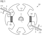
- the rotor body 110 shown in an axial plan view of a FSM rotor 100 to be produced has, for example, six identically designed poles or pole cores 120, which act as winding bodies and on each of which a pole winding 140 is produced or deposited.
- the poles 120 are wrapped with a wire or winding wire 130 using needle winding technology.
- the rotor body 110 is arranged in a needle winding device or machine, which is not shown in the figures. in particular a needle winding device according to the invention (as described above).
- two poles 120 that are opposite one another or offset by 180° with respect to the rotor or axis of rotation L are simultaneously wrapped in succession until all poles 120 have been wrapped. Provision is preferably made for the winding needles 120 to execute synchronous movements, as explained above.
- the winding needles 210 and the rotor body 110 to be wound carry out coordinated movements during a winding process or partial winding process (see above).
- a preferred concept for a corresponding kinematic control provides the following:
- the winding needles 210 only perform movements, in particular synchronous movements, in the radial direction R and in the circumferential direction U with respect to the rotor body 110 .
- the winding needles 210 also carry out pivoting movements, in particular synchronous pivoting movements, in order to react to structurally caused interference contours on the rotor body 110 .
- the rotor body 110 only performs axial movements (perpendicular to the sheet or plane of representation), in particular alternating axial movements, and also rotational or rotational movements D, in particular alternating rotational movements.
- the control device is designed accordingly.
- the movements of the winding needles 210, in particular the synchronous movements of the winding needles, and the movements of the rotor body 110 are preferably kinematically coordinated in such a way that the winding needles 210 (only) perform the smallest possible movements, in particular with the smallest possible distances or adjustment paths.
- a comparatively quiet winding process is achieved.
- the control of the needle winding device or the winding process is considerably simplified and on the other hand a comparatively simple structure of the needle winding units is made possible, which is particularly advantageous with regard to the adaptation and use of an existing needle winding machine.
Landscapes
- Engineering & Computer Science (AREA)
- Manufacturing & Machinery (AREA)
- Power Engineering (AREA)
- Manufacture Of Motors, Generators (AREA)
Applications Claiming Priority (1)
| Application Number | Priority Date | Filing Date | Title |
|---|---|---|---|
| DE102022101395.2A DE102022101395A1 (de) | 2022-01-21 | 2022-01-21 | Nadelwickelvorrichtung und Nadelwickelverfahren zum Erzeugen der Polwicklungen eines FSM-Rotors |
Publications (1)
| Publication Number | Publication Date |
|---|---|
| EP4216412A1 true EP4216412A1 (fr) | 2023-07-26 |
Family
ID=83457059
Family Applications (1)
| Application Number | Title | Priority Date | Filing Date |
|---|---|---|---|
| EP22197764.8A Pending EP4216412A1 (fr) | 2022-01-21 | 2022-09-26 | Dispositif d'enroulement d'aiguille et procédé d'enroulement d'aiguille pour produire des enroulements polaires d'un rotor fsm |
Country Status (2)
| Country | Link |
|---|---|
| EP (1) | EP4216412A1 (fr) |
| DE (1) | DE102022101395A1 (fr) |
Families Citing this family (1)
| Publication number | Priority date | Publication date | Assignee | Title |
|---|---|---|---|---|
| DE102022101395A1 (de) | 2022-01-21 | 2023-07-27 | Audi Aktiengesellschaft | Nadelwickelvorrichtung und Nadelwickelverfahren zum Erzeugen der Polwicklungen eines FSM-Rotors |
Citations (21)
| Publication number | Priority date | Publication date | Assignee | Title |
|---|---|---|---|---|
| JPS5917851A (ja) * | 1982-07-16 | 1984-01-30 | Shukichi Sakuma | 多極コアの巻線方法 |
| US4921178A (en) * | 1986-10-06 | 1990-05-01 | Garphyttan Industrier Ab | Machine for winding a rotor for a rotating electrical machine |
| JPH08126239A (ja) * | 1994-10-20 | 1996-05-17 | Nippondenso Co Ltd | 回転電機の電機子及びその巻装方法 |
| JPH10336977A (ja) * | 1997-05-30 | 1998-12-18 | Mitsubishi Electric Corp | アマチュアコイルの巻線装置及びアマチュアコイルの巻線方法 |
| US6003805A (en) | 1997-05-13 | 1999-12-21 | Globe Products Inc. | Adjustable stator winding head and method for adjusting the same |
| EP1294083A2 (fr) * | 2001-09-07 | 2003-03-19 | Kabushiki Kaisha Moric | Procédé et dispositif de bobinage pour induit de machine électrique tournante |
| US20030106955A1 (en) * | 1999-08-12 | 2003-06-12 | Raffaelle Becherucci | Winding cores with stratification motion |
| DE10360007A1 (de) * | 2003-12-19 | 2005-07-14 | Hilti Ag | Drehzahleinstellung bei einem Gleichstrommotor |
| DE102008041664A1 (de) * | 2008-08-28 | 2010-03-04 | Brose Fahrzeugteile GmbH & Co. Kommanditgesellschaft, Würzburg | Kommutatormotor, Verfahren zum Herstellen eines Ankerläufers und Antiblockierbremsvorrichtung |
| JP2011091885A (ja) | 2009-10-20 | 2011-05-06 | Mitsuba Corp | ブラシレスモータの巻線方法、およびブラシレスモータのバスバーユニット |
| DE102012212385A1 (de) * | 2012-07-16 | 2014-01-16 | Robert Bosch Gmbh | Vorrichtung und Verfahren zur Bewicklung eines Elektromotor-Blechpakets mit einer Magnetspule |
| EP2770618A1 (fr) * | 2011-10-18 | 2014-08-27 | Mitsuba Corporation | Moteur électrique et procédé d'enroulement d'un fil d'enroulement du moteur électrique |
| EP1966872B1 (fr) | 2005-12-23 | 2015-01-21 | Aumann GmbH | Dispositif pour bobiner un rotor avec un commutateur et procédé de fabrication correspondant |
| DE102014006406B4 (de) | 2014-04-25 | 2018-01-04 | Audi Ag | Vorrichtung und Verfahren zum Bewickeln eines Wicklungsträgers |
| DE102017208150A1 (de) * | 2017-05-15 | 2018-11-15 | Robert Bosch Gmbh | Elektromotor |
| DE102017006083A1 (de) * | 2017-06-28 | 2019-01-03 | Audi Ag | Verfahren und Wickelmaschine zum automatisierten Herstellen einer Spulenwicklung unter Berücksichtigung des Drahtdurchmessers |
| DE102019205101A1 (de) * | 2019-04-10 | 2020-10-15 | Audi Ag | Verfahren zum Herstellen eines elektromechanischen Bauteils |
| DE102019207865A1 (de) | 2019-05-29 | 2020-12-03 | Audi Ag | Wickelnadel, Wickelsystem für Drahtwicklungen und Verfahren zur Herstellung einer Drahtwicklung |
| DE102019214972A1 (de) | 2019-09-30 | 2021-04-01 | Robert Bosch Gmbh | Rotor, Verfahren zum Herstellen des Rotors und elektrische Maschine |
| DE102019217014A1 (de) * | 2019-11-05 | 2021-05-06 | Robert Bosch Gmbh | Maschinenkomponente, Verfahren zum Herstellen der Maschinenkomponente und elektrische Maschine |
| DE102022101395A1 (de) | 2022-01-21 | 2023-07-27 | Audi Aktiengesellschaft | Nadelwickelvorrichtung und Nadelwickelverfahren zum Erzeugen der Polwicklungen eines FSM-Rotors |
Family Cites Families (6)
| Publication number | Priority date | Publication date | Assignee | Title |
|---|---|---|---|---|
| CH651705A5 (de) | 1980-02-11 | 1985-09-30 | Micafil Ag | Wickelvorrichtung zum bewickeln von mit wickelkopfabstuetzungen versehenen statoren elektrischer maschinen. |
| US5267699A (en) | 1992-03-11 | 1993-12-07 | Axis Usa, Inc. | Methods of winding armatures with modified side pattern |
| JPH11164533A (ja) | 1997-11-25 | 1999-06-18 | Asmo Co Ltd | 電動機、電機子及びその巻線方法 |
| JP3380885B2 (ja) | 2000-05-25 | 2003-02-24 | 株式会社林工業所 | モータ固定子の巻線方法及び巻線装置 |
| JP4285559B2 (ja) | 2007-04-26 | 2009-06-24 | 株式会社デンソー | 回転子の巻線装置及び回転子の製造方法 |
| WO2017009052A1 (fr) | 2015-07-15 | 2017-01-19 | Brose Fahrzeugteile GmbH & Co. Kommanditgesellschaft, Würzburg | Stator et procédé de fabrication d'un stator |
-
2022
- 2022-01-21 DE DE102022101395.2A patent/DE102022101395A1/de not_active Withdrawn
- 2022-09-26 EP EP22197764.8A patent/EP4216412A1/fr active Pending
Patent Citations (22)
| Publication number | Priority date | Publication date | Assignee | Title |
|---|---|---|---|---|
| JPS5917851A (ja) * | 1982-07-16 | 1984-01-30 | Shukichi Sakuma | 多極コアの巻線方法 |
| US4921178A (en) * | 1986-10-06 | 1990-05-01 | Garphyttan Industrier Ab | Machine for winding a rotor for a rotating electrical machine |
| JPH08126239A (ja) * | 1994-10-20 | 1996-05-17 | Nippondenso Co Ltd | 回転電機の電機子及びその巻装方法 |
| US6003805A (en) | 1997-05-13 | 1999-12-21 | Globe Products Inc. | Adjustable stator winding head and method for adjusting the same |
| JPH10336977A (ja) * | 1997-05-30 | 1998-12-18 | Mitsubishi Electric Corp | アマチュアコイルの巻線装置及びアマチュアコイルの巻線方法 |
| US20030106955A1 (en) * | 1999-08-12 | 2003-06-12 | Raffaelle Becherucci | Winding cores with stratification motion |
| EP1294083A2 (fr) * | 2001-09-07 | 2003-03-19 | Kabushiki Kaisha Moric | Procédé et dispositif de bobinage pour induit de machine électrique tournante |
| DE10360007A1 (de) * | 2003-12-19 | 2005-07-14 | Hilti Ag | Drehzahleinstellung bei einem Gleichstrommotor |
| EP1966872B1 (fr) | 2005-12-23 | 2015-01-21 | Aumann GmbH | Dispositif pour bobiner un rotor avec un commutateur et procédé de fabrication correspondant |
| DE102008041664A1 (de) * | 2008-08-28 | 2010-03-04 | Brose Fahrzeugteile GmbH & Co. Kommanditgesellschaft, Würzburg | Kommutatormotor, Verfahren zum Herstellen eines Ankerläufers und Antiblockierbremsvorrichtung |
| JP2011091885A (ja) | 2009-10-20 | 2011-05-06 | Mitsuba Corp | ブラシレスモータの巻線方法、およびブラシレスモータのバスバーユニット |
| JP5563802B2 (ja) * | 2009-10-20 | 2014-07-30 | 株式会社ミツバ | ブラシレスモータの巻線方法 |
| EP2770618A1 (fr) * | 2011-10-18 | 2014-08-27 | Mitsuba Corporation | Moteur électrique et procédé d'enroulement d'un fil d'enroulement du moteur électrique |
| DE102012212385A1 (de) * | 2012-07-16 | 2014-01-16 | Robert Bosch Gmbh | Vorrichtung und Verfahren zur Bewicklung eines Elektromotor-Blechpakets mit einer Magnetspule |
| DE102014006406B4 (de) | 2014-04-25 | 2018-01-04 | Audi Ag | Vorrichtung und Verfahren zum Bewickeln eines Wicklungsträgers |
| DE102017208150A1 (de) * | 2017-05-15 | 2018-11-15 | Robert Bosch Gmbh | Elektromotor |
| DE102017006083A1 (de) * | 2017-06-28 | 2019-01-03 | Audi Ag | Verfahren und Wickelmaschine zum automatisierten Herstellen einer Spulenwicklung unter Berücksichtigung des Drahtdurchmessers |
| DE102019205101A1 (de) * | 2019-04-10 | 2020-10-15 | Audi Ag | Verfahren zum Herstellen eines elektromechanischen Bauteils |
| DE102019207865A1 (de) | 2019-05-29 | 2020-12-03 | Audi Ag | Wickelnadel, Wickelsystem für Drahtwicklungen und Verfahren zur Herstellung einer Drahtwicklung |
| DE102019214972A1 (de) | 2019-09-30 | 2021-04-01 | Robert Bosch Gmbh | Rotor, Verfahren zum Herstellen des Rotors und elektrische Maschine |
| DE102019217014A1 (de) * | 2019-11-05 | 2021-05-06 | Robert Bosch Gmbh | Maschinenkomponente, Verfahren zum Herstellen der Maschinenkomponente und elektrische Maschine |
| DE102022101395A1 (de) | 2022-01-21 | 2023-07-27 | Audi Aktiengesellschaft | Nadelwickelvorrichtung und Nadelwickelverfahren zum Erzeugen der Polwicklungen eines FSM-Rotors |
Non-Patent Citations (4)
| Title |
|---|
| FLEISCHER J., HAAG, S.HOFMANN, J: "Quo Vadis Winding Technology? A study on the state of the art and research on future trends in automotive engineering", KARLSRUHE INSTITUTE OF TECHNOLOGY, 1 January 2017 (2017-01-01), pages 1 - 38, XP093353359, Retrieved from the Internet <URL:https://www.wbk.kit.edu/downloads/2017_02_21_Studie_Wickeltechnik_final_EN.pdf> |
| ROSS FROM MOTOR MACHINES MANUFACTURER: "double flyers armature winding machine", 8 April 2015 (2015-04-08), XP093140820, Retrieved from the Internet <URL:https://www.youtube.com/watch?v=S_tnd_vFDW0> [retrieved on 20240313] * |
| ROSS FROM MOTOR MACHINES MANUFACTURER: "double flyers armature winding machine", YOUTUBE, 8 April 2015 (2015-04-08), XP093140820, Retrieved from the Internet <URL:https://www.youtube.com/watch?v=S_tnd_vFDW0> [retrieved on 20240313] |
| ROSS FROM MOTOR MACHINES MANUFACTURER: "double flyers armature winding machine", YOUTUBE, 9 April 2015 (2015-04-09), XP093140820, Retrieved from the Internet <URL:https://www.youtube.com/watch?v=S_tnd_vFDW0> [retrieved on 20240313] |
Also Published As
| Publication number | Publication date |
|---|---|
| DE102022101395A1 (de) | 2023-07-27 |
Similar Documents
| Publication | Publication Date | Title |
|---|---|---|
| EP3840198B1 (fr) | Dispositif et procédé de flexion du fil pour un élément de machine d'une machine électrique | |
| DE102011008662A1 (de) | Nadelwickelsystem für zu bewickelnde Wicklungsträger, Verfahren zum Bewickeln von Wicklungsträgern mit verteilter Wicklung, Innenläufer-Stator, Außenläufer-Rotor und Wicklungsträger für Elektromotorn mit verteilter Wicklung | |
| EP0968563A1 (fr) | Procede et dispositif de production d'enroulements ondules pour machines electriques | |
| WO2007048566A1 (fr) | Moteur electrique et procede de bobinage | |
| WO2007006668A1 (fr) | Procede pour produire un enroulement d'une machine electrique | |
| DE102010053719A1 (de) | Verfahren zur Herstellung einer Ständerwicklung einer elektrischen Maschine, insbesondere zur Herstellung eines Wechselstromgenerators | |
| AT520356A1 (de) | Verfahren und Vorrichtung zur automatisierten Herstellung einer Komponente eines Stators oder Rotors einer elektrischen Maschine | |
| EP4175139A1 (fr) | Dispositif et procédé de fabrication d'une flexion d'un enroulement ondulé pour un enroulement de bobine d'une machine électrique | |
| DE102022101395A1 (de) | Nadelwickelvorrichtung und Nadelwickelverfahren zum Erzeugen der Polwicklungen eines FSM-Rotors | |
| WO2017045873A1 (fr) | Installation et procédé pour produire une barre d'enroulement pour un enroulement de stator | |
| DE102019208227A1 (de) | Verfahren zur Herstellung einer Statorwicklung und Elektromaschine | |
| EP2269285B1 (fr) | Procede et dispositif de fabrication d'un bobinage electrique | |
| DE102023200669A1 (de) | Verfahren zur Herstellung einer Wickelmatte | |
| EP3167540A1 (fr) | Procédé de fabrication d'une machine électrique comportant des bobines formées et machine électrique et outil de fabrication | |
| EP4233159B1 (fr) | Appareil de cintrage d'extrémités de fil et procédé de cintrage d'extrémités de fil lors de la production d'un composant de machine électrique pourvu de bobines | |
| EP4311090A1 (fr) | Agencement d'un enroulement de fil dans un corps magnétisable guide de flux d'un stator d'une machine électrique tournante à rotor interne | |
| EP3195451A1 (fr) | Procédé de bobinage d'une pluralité de carcasses de bobines et mandrin segmenté | |
| DE102023201316A1 (de) | Biegevorrichtung zur Herstellung einer Wickelmatte für einen Rotor oder einen Stator einer elektrischen Maschine | |
| DE102022111470A1 (de) | Vorrichtung und Verfahren zum Schränken von Leiterenden einer Spulenwicklung für eine elektrische Maschine | |
| DE102023200094A1 (de) | Wellenwicklung eines Rotors oder eines Stators einer elektrischen Maschine und Wickelverfahren zur Herstellung einer Wickelmatte | |
| DE102013000370B4 (de) | Wicklungsträger, insbesondere Stator oder Rotor einer Drehstrom-Elektromaschine und Verfahren zur Herstellung der Wicklung eines Wicklungsträgers | |
| DE102023126681A1 (de) | Verfahren zur Herstellung eines Stators für eine elektrische Maschine; Stator für eine elektrische Maschine; sowie Umformwerkzeug | |
| DE102014222376A1 (de) | Statorwicklung für eine elektrische Maschine, elektrische Maschine mit der Statorwicklung, und Verfahren zu deren Herstellung | |
| DE102022204153A1 (de) | Verfahren zum Erzeugen einer automatisierten Wicklungsprozedur | |
| WO2023222516A1 (fr) | Procédé et dispositif de production d'un voile d'enroulement pour un stator ou un rotor d'un moteur électrique |
Legal Events
| Date | Code | Title | Description |
|---|---|---|---|
| PUAI | Public reference made under article 153(3) epc to a published international application that has entered the european phase |
Free format text: ORIGINAL CODE: 0009012 |
|
| STAA | Information on the status of an ep patent application or granted ep patent |
Free format text: STATUS: THE APPLICATION HAS BEEN PUBLISHED |
|
| AK | Designated contracting states |
Kind code of ref document: A1 Designated state(s): AL AT BE BG CH CY CZ DE DK EE ES FI FR GB GR HR HU IE IS IT LI LT LU LV MC MK MT NL NO PL PT RO RS SE SI SK SM TR |
|
| TPAC | Observations filed by third parties |
Free format text: ORIGINAL CODE: EPIDOSNTIPA |
|
| STAA | Information on the status of an ep patent application or granted ep patent |
Free format text: STATUS: REQUEST FOR EXAMINATION WAS MADE |
|
| 17P | Request for examination filed |
Effective date: 20240126 |
|
| RBV | Designated contracting states (corrected) |
Designated state(s): AL AT BE BG CH CY CZ DE DK EE ES FI FR GB GR HR HU IE IS IT LI LT LU LV MC MK MT NL NO PL PT RO RS SE SI SK SM TR |
|
| STAA | Information on the status of an ep patent application or granted ep patent |
Free format text: STATUS: EXAMINATION IS IN PROGRESS |
|
| 17Q | First examination report despatched |
Effective date: 20240503 |
|
| TPAC | Observations filed by third parties |
Free format text: ORIGINAL CODE: EPIDOSNTIPA |
|
| TPAC | Observations filed by third parties |
Free format text: ORIGINAL CODE: EPIDOSNTIPA |
|
| TPAC | Observations filed by third parties |
Free format text: ORIGINAL CODE: EPIDOSNTIPA |