EP4216537A1 - Dispositif de traitement d'image et programme de traitement d'image - Google Patents
Dispositif de traitement d'image et programme de traitement d'image Download PDFInfo
- Publication number
- EP4216537A1 EP4216537A1 EP21868952.9A EP21868952A EP4216537A1 EP 4216537 A1 EP4216537 A1 EP 4216537A1 EP 21868952 A EP21868952 A EP 21868952A EP 4216537 A1 EP4216537 A1 EP 4216537A1
- Authority
- EP
- European Patent Office
- Prior art keywords
- unit
- image
- cutout position
- strength
- vector
- Prior art date
- Legal status (The legal status is an assumption and is not a legal conclusion. Google has not performed a legal analysis and makes no representation as to the accuracy of the status listed.)
- Pending
Links
Images


Classifications
-
- H—ELECTRICITY
- H04—ELECTRIC COMMUNICATION TECHNIQUE
- H04N—PICTORIAL COMMUNICATION, e.g. TELEVISION
- H04N23/00—Cameras or camera modules comprising electronic image sensors; Control thereof
- H04N23/60—Control of cameras or camera modules
- H04N23/68—Control of cameras or camera modules for stable pick-up of the scene, e.g. compensating for camera body vibrations
- H04N23/681—Motion detection
- H04N23/6812—Motion detection based on additional sensors, e.g. acceleration sensors
-
- H—ELECTRICITY
- H04—ELECTRIC COMMUNICATION TECHNIQUE
- H04N—PICTORIAL COMMUNICATION, e.g. TELEVISION
- H04N23/00—Cameras or camera modules comprising electronic image sensors; Control thereof
- H04N23/60—Control of cameras or camera modules
- H04N23/61—Control of cameras or camera modules based on recognised objects
-
- G—PHYSICS
- G06—COMPUTING OR CALCULATING; COUNTING
- G06T—IMAGE DATA PROCESSING OR GENERATION, IN GENERAL
- G06T7/00—Image analysis
- G06T7/20—Analysis of motion
-
- H—ELECTRICITY
- H04—ELECTRIC COMMUNICATION TECHNIQUE
- H04N—PICTORIAL COMMUNICATION, e.g. TELEVISION
- H04N23/00—Cameras or camera modules comprising electronic image sensors; Control thereof
- H04N23/60—Control of cameras or camera modules
- H04N23/68—Control of cameras or camera modules for stable pick-up of the scene, e.g. compensating for camera body vibrations
- H04N23/681—Motion detection
- H04N23/6811—Motion detection based on the image signal
-
- H—ELECTRICITY
- H04—ELECTRIC COMMUNICATION TECHNIQUE
- H04N—PICTORIAL COMMUNICATION, e.g. TELEVISION
- H04N23/00—Cameras or camera modules comprising electronic image sensors; Control thereof
- H04N23/60—Control of cameras or camera modules
- H04N23/68—Control of cameras or camera modules for stable pick-up of the scene, e.g. compensating for camera body vibrations
- H04N23/682—Vibration or motion blur correction
- H04N23/683—Vibration or motion blur correction performed by a processor, e.g. controlling the readout of an image memory
-
- G—PHYSICS
- G06—COMPUTING OR CALCULATING; COUNTING
- G06T—IMAGE DATA PROCESSING OR GENERATION, IN GENERAL
- G06T2207/00—Indexing scheme for image analysis or image enhancement
- G06T2207/20—Special algorithmic details
- G06T2207/20212—Image combination
- G06T2207/20221—Image fusion; Image merging
Definitions
- the present invention relates to an image processing device and an image processing program that process each frame of video captured by an image capturing unit.
- the electronic camera shake correction feature adaptively shifts the range of angle of view to be cut out from an image-capturing range so as to cancel out camera shake, thereby generating an image with a reduced blur.
- control is performed such that the position of a subject within the angle of view is fixed as much as possible.
- the viewpoint moves due to the movement of the camera, the compositional arrangement within the angle of view changes, and the appearance of the positional relationship between the object and the background changes.
- Patent Literature 1 discloses a technique of combining parallax images obtained by imaging a subject space from different viewpoints so as to synthesize an image close to the image before the viewpoint change.
- this technique requires an imaging element having multiple pixels for one microlens, which complicates the optical system.
- Patent Literature 1 Japanese Patent Application Publication No. 2016-42662
- a purpose of the present embodiment is to provide a technique for electronically generating video that is stable including compositional arrangement even if the image-capturing viewpoint is shaken.
- An image processing device includes: a video acquisition unit that acquires video captured by an image capturing unit; a movement amount identification unit that identifies the amount of movement of the image capturing unit that is based on vibration applied to the image capturing unit based on an output signal from a sensor for detecting vibration applied to the image capturing unit or a difference between frames of the acquired video; an object detection unit that detects an object of interest from within frames of the acquired video; a distance identification unit that identifies the distance from the image capturing unit to the object based on an output signal from a sensor for measuring a distance and the size of the object in a frame; a vector strength adjustment unit that adjusts the strength of a correction vector for cancelling out shake caused by the vibration; a cutout position determination unit that determines a cutout position for cutting out an image of a predetermined size from each of the frames of the acquired video and that moves the cutout position in accordance with the correction vector and separately determines an object cutout position and a background cutout position according to the
- video that is stable including compositional arrangement can be electronically generated even if the image-capturing viewpoint is shifted.
- FIG. 1 is a diagram showing the configuration of an image capturing device 1 according to the first embodiment of the present invention.
- the image capturing device 1 may be a stand-alone video camera or a camera module installed in an information device such as a smartphone, a tablet, or a laptop computer.
- the image capturing device 1 includes an image capturing unit 10, a vibration detection sensor 11, and an image processing device 20.
- the image capturing unit 10 includes a lens, a solid-state image sensor, and a signal processing circuit.
- CMOS complementary metal oxide semiconductor
- CCD charge coupled device
- the solid-state image sensor converts light incident through the lens into an electrical video signal and outputs the signal to the signal processing circuit.
- the signal processing circuit performs signal processing such as A/D conversion, noise removal, and the like on the video signal input from the solid-state image sensor and outputs the resulting video signal to the image processing device 20.
- the vibration detection sensor 11 detects vibration applied to the image capturing unit 10 and outputs the result to the image processing device 20.
- a gyro sensor can be used for the vibration detection sensor 11.
- the gyro sensor detects vibrations applied to the image capturing unit 10 in the yaw direction and in the pitch direction each as angular velocity.
- the image processing device 20 includes a video acquisition unit 21, an image recognition unit 22, an object detection unit 23, an object tracking unit 24, a motion vector detection unit 25, a cutout position determination unit 27, a vibration information acquisition unit 28, a movement amount identification unit 29, a cutout unit 30, an image composition unit 31, and a pixel interpolation unit 32.
- These components can be realized by the cooperation of hardware resources and software resources or only by hardware resources.
- CPU, ROM, RAM, graphics processing unit (GPU), digital signal processor (DSP), image signal processor (ISP), application specific integrated circuit (ASIC), field-programmable gate array (FPGA), and other LSIs can be used.
- firmware and other programs can be used as the software resources.
- the video acquisition unit 21 acquires video captured by the image capturing unit 10.
- the vibration information acquisition unit 28 acquires an output signal from the vibration detection sensor 11 as vibration component information.
- the movement amount identification unit 29 integrates the output signal acquired by the vibration information acquisition unit 28 so as to identify the movement amount of the image capturing unit 10. For example, the movement amount identification unit 29 integrates angular velocity signals in the yaw direction and the pitch direction acquired by the vibration information acquisition unit 28, respectively, so as to calculate the respective angles of movement of the image capturing unit 10 in the yaw direction and the pitch direction.
- the movement amount identification unit 29 detects from the difference between frames that the entire background area, excluding an object recognized by the image recognition unit 22 described below, is evenly moving in the same direction, the movement amount of the entire background area may be identified as the movement amount of the image capturing unit 10. In this case, even if the vibration detection sensor 11 is omitted, the movement amount of the image capturing unit 10 based on the vibration applied to the image capturing unit 10 can be estimated. The omission of the vibration detection sensor 11 allows the cost to be reduced.
- the movement amount identification unit 29 generates a correction vector for cancelling out the identified movement amount of the image capturing unit 10. That is, the movement amount identification unit 29 generates a correction vector having the same amount of correction as the amount of movement of the image capturing unit 10 in the direction of the shaking of the image capturing unit 10. The movement amount identification unit 29 outputs the generated correction vector to the cutout position determination unit 27. When the image capturing unit 10 is ideally stationary, the value of the correction vector is zero.
- the image recognition unit 22 searches for an object from within a frame of the video acquired by the video acquisition unit 21.
- the image recognition unit 22 has, as dictionary data, an identifier for a specific object generated by learning a large number of images in which a specific object are shown.
- Specific objects are, for example, the face of a person, the whole body of a person, the face of an animal (e.g., a dog or cat), the whole body of an animal, a vehicle (e.g., a railroad vehicle), etc.
- the image recognition unit 22 searches within the frame of the video using the identifier for each object. For example, histograms of oriented gradients (HOG) feature values can be used for the recognition of an object. Haarlike feature values, local binary patterns (LBP) feature values, or the like may also be used. When an object exists within the frame, the image recognition unit 22 captures the object with a rectangular detection frame.
- HOG histograms of oriented gradients
- LBP local binary patterns
- the object detection unit 23 determines whether or not to detect an object recognized by the image recognition unit 22 as an object of interest.
- the object of interest is the object that is presumed to be a subject that the user (photographer) of the image capturing device 1 is paying attention to.
- the object detection unit 23 determines whether or not the recognized object serves as the subject based on any one or a combination of the criteria as follows: (a) Whether the object is larger than a predetermined size, (b) whether the object is located in the central area of the frame, (c) whether the object is a person or animal, (d) whether the distance to the object is less than a predetermined value (the method for estimating the distance to the object is described below), (e) whether there is no part of the object that is hidden, and (f) whether the motion of the object is smaller than a predetermined value (the method for detecting the motion is described below).
- the object detection unit 23 may detect all objects that satisfy the above criteria as subjects or may select one subject based on any one or a combination of the criteria as follows: (a)' whether the object is the largest object in the frame, (b)' whether the object is most centrally located in the frame, (d)' whether the distance to the object is the shortest, (f)' whether the object has the smallest motion among the moving objects.
- the object detection unit 23 may determine an object touched by the user of the image capturing device 1 to be the subject from among objects shown on the viewfinder screen.
- the object tracking unit 24 tracks an object recognized by the image recognition unit 22 in the subsequent frame.
- a particle filter or the mean shift method may be used to track the object.
- Objects to be tracked may be all the objects recognized by the image recognition unit 22 or only those detected as objects of interest by the object detection unit 23. If the motion of an object is used as the selection criterion for the subject, all the objects recognized by the image recognition unit 22 need to be tracked.
- the motion vector detection unit 25 detects the amount of movement of an object of interest between frames of video as the motion vector of the object. This motion vector indicates the forward vector (tracking vector) of the motion of the object.
- the cutout position determination unit 27 determines the cutout position for cutting out an image of a predetermined size from each frame of the video.
- the cutout position determination unit 27 cuts out a partial area from the entire image-capturing range captured by all pixels of the solid-state image sensor and determines the range of an image to be displayed or recorded.
- an electronic image stabilization feature is employed.
- the electronic image stabilization feature adaptively changes the position of the angle of view to be cut out from the entire image-capturing range so as to cancel out the camera shake of the image capturing device 1.
- a subject tracking feature is also employed.
- the subject tracking feature changes the position of the angle of view to be cut out from the entire image-capturing range such that the position of the subject within the angle of view is fixed as much as possible relative to the motion of the subject.
- real-time angle-of-view cutout is performed by the electronic image stabilization feature and the subject tracking feature.
- the cutout position determination unit 27 acquires a correction vector from the movement amount identification unit 29 and acquires the position of the object of interest and a motion vector from the motion vector detection unit 25.
- the cutout position determination unit 27 separately determines the cutout position of the object of interest and the cutout position of the background.
- the cutout position determination unit 27 determines an object cutout position in the current frame by moving an object cutout position in the reference frame in accordance with a composite vector in which the correction vector and the motion vector of the object are combined.
- the correction vector is a correction vector for cancelling out the motion of the image capturing unit 10 between the previous frame and the current frame
- the motion vector of the object is a motion vector indicating the motion of the object between the previous frame and the current frame.
- the reference frame is a frame at the start of the tracking of the object
- the correction vector is a correction vector for cancelling out the motion of the image capturing unit 10 between the frame at the start of the tracking and the current frame
- the motion vector of the object is a motion vector indicating the motion of the object between the frame at the start of the tracking and the current frame.
- the cutout position determination unit 27 moves a background cutout position of the reference frame in accordance with the correction vector so as to determine the background cutout position of the current frame. If the reference frame is the previous frame, the correction vector is a correction vector for cancelling out the motion of the image capturing unit 10 between the previous frame and the current frame. If the reference frame is the frame at the start of the tracking of the object, the correction vector is a correction vector for cancelling out the motion of the image capturing unit 10 between the frame at the start of the tracking and the current frame.
- the cutout position determination unit 27 may determine the background cutout position by moving the object cutout position in the current frame in accordance with the inverse vector of the motion vector of the object.
- the motion vector of the object is a motion vector indicating the motion between the frame at the start of the tracking and the current frame.
- the cutout unit 30 cuts out only image data of the object from image data of the object cutout position.
- the cutout unit 30 cuts out image data of the background excluding the object from image data of the background cutout position.
- the image composition unit 31 combines the cut-out image data of the object and the cut-out image data of the background.
- the pixel interpolation unit 32 interpolates for the defective pixels in the combined image based on at least one effective pixel spatially or temporally proximate to the defective pixels.
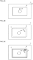
- FIGS. 2A to 2C are diagrams for explaining specific examples of composite image generation processing performed by the image processing device 20 according to the first embodiment (Part 1).
- FIGS. 3A to 3C are diagrams for explaining specific examples of composite image generation processing performed by the image processing device 20 according to the first embodiment (Part 2).
- the cutout position determination unit 27 sets a cutout position C0 at the center of a frame F0 by default.
- the object detection unit 23 detects an object OB1 in the frame F0 as an object of interest.
- the object tracking unit 24 starts tracking the object OB1.
- the object OB1 is moving to the left.
- the image capturing unit 10 is moving upward due to camera shake by the photographer.
- the cutout position determination unit 27 moves the cutout position C0 of the reference frame F0 according to the composite vector of the correction vector for camera shake and the motion vector of the object OB1 and determines a cutout position C1 for the object OB1 in the current frame F1.
- the cutout position determination unit 27 moves the cutout position C1 for the object OB1 in the current frame F1 according to the inverse vector of the motion vector of the object OB1 and determines a cutout position C2 for the background.
- the cutout unit 30 cuts out image data of the object OB1 from image data of the cutout position C1 for the object OB1 in the current frame F1.
- the cutout unit 30 cuts out image data of the background excluding the image data of the object OB1 from image data of the cutout position C2 for the background of the current frame F1.
- the image composition unit 31 combines the cut-out image data of the object OB1 and the cut-out image data of the background so as to generate a new composite image Ic.
- the angle of view for the subject and the angle of view for the background are cut out separately, and background blur correction is performed for the angle of view for the background.
- Background blur can be suppressed by combining the field angle for the subject and the field angle for the background after the background blur correction.
- camera shake correction is performed for both the field angle for the subject and the field angle for the background. This allows for the generation of video in which blurring is suppressed over the entire angle of view.
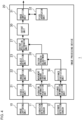
- FIG. 4 is a diagram showing the configuration of an image capturing device 1 according to the second embodiment of the present invention.
- the image capturing device 1 according to the second embodiment includes an image capturing unit 10, a vibration detection sensor 11, a distance detection sensor 12, and an image processing device 20.
- the image processing device 20 according to the second embodiment includes a video acquisition unit 21, an image recognition unit 22, an object detection unit 23, a vector strength adjustment unit 26, a cutout position determination unit 27, a vibration information acquisition unit 28, a movement amount identification unit 29, a cutout unit 30, an image composition unit 31, a pixel interpolation unit 32, a distance information acquisition unit 33, and a distance identification unit 34.
- the distance detection sensor 12 is a sensor for detecting the distance of an object in the image-capturing direction from the image capturing unit 10.
- a Time of Flight (TOF) sensor can be used for the distance detection sensor 12.
- Typical TOF sensors include ultrasonic sensors (sonar) and light detection and ranging (LiDAR).
- Ultrasonic sensors emit ultrasonic waves in the image-capturing direction and measure the time it takes to receive the reflected waves so as to detect the distance to an object in the image-capturing direction.
- LiDAR emit laser light in the image-capturing direction and measure the time it takes to receive the reflected light so as to detect the distance to an object in the image-capturing direction.
- the distance information acquisition unit 33 acquires an output signal from the distance detection sensor 12 as distance information.
- the distance identification unit 34 generates a distance image corresponding to a visible light image captured by the image capturing unit 10 based on the acquired distance information.
- the distance identification unit 34 may estimate the distance from the image capturing unit 10 to the object captured in the frame through image recognition. For example, the relationship among the general size of an object registered as dictionary data, the size of the object captured in a frame, and the distance from the image capturing unit 10 to the object is defined in advance by a table or a function. Based on the size of the object recognized by the image recognition unit 22 in the frame, the distance identification unit 34 estimates the distance from the image capturing unit 10 to the object with reference to the table or the function. In this case, even if the distance detection sensor 12 is omitted, the distance to the object shown in the frame can still be estimated. The omission of the distance detection sensor 12 can reduce the cost.
- the distance identification unit 34 can acquire the distance from the image capturing unit 10 to the object shown in the frame from an auto-focus adjustment unit (not shown), the distance identification unit 34 may use the distance acquired from the auto-focus adjustment unit. If the image capturing unit 10 is configured with twin lenses, the distance identification unit 34 may estimate the distance to the object shown in the frame based on parallax between video pictures captured by the twin-lens image capturing unit 10.
- the subject tracking feature is omitted in the second embodiment. Therefore, basically, there is no need to calculate the motion vector of an object, and the object tracking unit 24 and the motion vector detection unit 25 are omitted from the image processing device 20 in the second embodiment.
- An electronic image stabilization feature is also employed in the second embodiment.
- the position of the angle of view to be cut out from the entire image-capturing range is adaptively moved such that the camera shake of the image capturing device 1 is canceled out.
- a vector strength adjustment unit 26 for adjusting the strength of a correction vector for cancelling out camera shake is added.
- the vector strength adjustment unit 26 acquires a correction vector from the movement amount identification unit 29 and the distance to the object from the distance identification unit 34.
- the vector strength adjustment unit 26 adjusts the strength of a correction vector acquired from the movement amount identification unit 29 according to the distance to the object acquired from the distance identification unit 34.
- the vector strength adjustment unit 26 sets the strength of the correction vector to be stronger as the distance to the object is shorter and sets the strength of the correction vector to be weaker as the distance to the object is longer.
- the relationship among the amount of camera shake, the distance from the image capturing unit 10 to the object, and the amount of movement of the object shown in the frame caused due to camera shake is defined in advance by a table or a function. The relationship may be derived based on experiments or simulations by the designer.
- the vector strength adjustment unit 26 adjusts the strength of the correction vector acquired from the movement amount identification unit 29 based on the distance from the image capturing unit 10 to the object acquired from the distance identification unit 34 with reference to the table or the function.
- the cutout position determination unit 27 acquires the position of the object of interest from the object detection unit 23 and acquires the correction vector of the object from the vector strength adjustment unit 26.
- the cutout position determination unit 27 moves the cutout position of a reference frame (for example, the previous frame) in accordance with the correction vector so as to determine the cutout position of the current frame.
- the cutout position determination unit 27 determines the object cutout position and the background cutout position separately in accordance with the strength of the correction vector of the object and the strength of the correction vector of the background.
- the cutout position determination unit 27 determines a cutout position for each object of interest. For example, when a first object and a second object located behind the first object are detected as objects of interest in a frame, the vector strength adjustment unit 26 sets the strength of a correction vector for the first object to be stronger than that for the second object.
- the correction vector for the background may be used directly without adjusting the strength of the correction vector, or the vector strength adjustment unit 26 may adjust the strength of the correction vector.
- the entire background may be divided into multiple backgrounds according to distance divisions, and the vector strength adjustment unit 26 may adjust the strength of the correction vector for each divided background.
- the vector strength adjustment unit 26 may also adjust the strength of the correction vector based on a representative value (e.g., mean, median, or mode) of the distance to each object constituting the background.
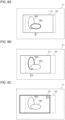
- FIGS. 5A to 5C are diagrams for explaining specific examples of composite image generation processing performed by the image processing device 20 according to the second embodiment (Part 1).
- FIGS. 6A to 6C are diagrams for explaining specific examples of composite image generation processing performed by the image processing device 20 according to the second embodiment (Part 2).
- FIGS. 7A and 7B are diagrams for explaining specific examples of composite image generation processing performed by the image processing device 20 according to the second embodiment (Part 3).
- the cutout position determination unit 27 sets the cutout position C0 at the center of the frame F0 by default.
- the object detection unit 23 detects the first object OB1 and the second object OB2 as objects of interest in the frame F0.
- the second object OB2 exists behind the first object OB1 when viewed from the image capturing unit 10, and part of the second object OB2 is hidden behind the first object OB1 in the frame F0.
- FIG. 5B shows a state in which the image capturing unit 10 has moved to the right from the state shown in FIG. 5A due to camera shake by the photographer.
- FIG. 5B shows a case where the electronic image stabilization feature is off. In this case, the first object OB1 and the second object OB2 move to the left side of the angle of view without changing the cutout position C0.
- the viewpoint moves to the right due to the movement of the image capturing unit 10 to the right, which changes the appearance of the relative positional relationship between the first object OB1 and the second object OB2. More specifically, in the current frame F1, the first object OB1 located closer to the viewpoint moves farther left than the second object OB2 located farther away from the viewpoint. That is, in the current frame F1, the overlap of the first object OB1 and the second object OB2 is larger, and a portion where the second object OB2 is hidden by the first object OB1 is larger, compared with the reference frame F0 before camera shake.
- FIG. 5C shows a case where the electronic camera shake correction feature is on and the cutout position C0 of the reference frame F0 has simply been moved to the left according to a camera shake correction vector.
- the cutout position C0 By moving the cutout position C0, the first object OB1 and the second object OB2 are arranged at the center of the angle of view at a cutout position C0' of the current frame F1.
- the compositional arrangement of the first object OB1 and the second object OB2 in the current frame F1 has changed compared to the reference frame F0.
- the cutout position determination unit 27 moves the cutout position C0 of the reference frame F0 according to the correction vector of the first object OB1 and determines the cutout position C1 for the first object OB1.
- the cutout position determination unit 27 moves the cutout position C0 of the reference frame F0 according to the correction vector of the second object OB2 and determines the cutout position C2 for the second object OB2.
- the cutout position determination unit 27 moves the cutout position C0 of the reference frame F0 according to the correction vector of the background and determines the cutout position C3 for the background.
- the cutout unit 30 cuts out the image data of the first object OB1 from the image data of the cutout position C1 for the first object OB1, cuts out the image data of the second object OB2 from the image data of the cutout position C2 for the second object OB2, and cuts out the image data of the background excluding the first object OB1 and the second object OB2 from the image data of the cutout position C3 for the background.
- the image composition unit 31 combines the cut-out image data of the first object OB1, the cut-out image data of the second object OB2, and the cut-out image data of the background so as to generate a new composite image Ic.
- compositional arrangement of the first object OB1 and the second object OB2 in the newly-generated composite image Ic is the same as the compositional arrangement of the first object OB1 and the second object OB2 in the cutout position C0 of the reference frame F0. That is, it is possible to perform pseudo viewpoint conversion as if the image capturing unit 10 were not moving.
- the overlap of the first object OB1 and the second object OB2 in the composite image Ic newly generated from the current frame F1 is smaller than the overlap of the first object OB1 and the second object OB2 actually shown in the current frame F1. Therefore, in the newly-generated composite image Ic, missing of pixels occurs in the area of the difference between the overlapping portions of the two. That is, the partial area hidden by the first object OB1 becomes a defective pixel area Rm.
- the pixel interpolation unit 32 interpolates pixels in this defective pixel area Rm based on at least one effective pixel spatially or temporally close to the defective pixel area Rm. As the first interpolation method, the pixel interpolation unit 32 generates complementary pixels from peripheral pixels adjacent to the defective pixel area Rm in the current frame F1.
- the pixel interpolation unit 32 assigns each pixel in the defective pixel area Rm the same pixel as the effective pixel closest to the pixel. For example, the pixel interpolation unit 32 may assign a representative value of multiple effective pixels adjacent to the defective pixel area Rm to a pixel in the defective pixel area Rm. For each pixel in the defective pixel area Rm, multiple effective pixels in close proximity may be identified, and a representative value of the multiple identified effective pixels may be calculated.
- the pixel interpolation unit 32 may interpolate multiple pixels in the defective pixel area Rm in between. For example, linear interpolation may be performed line by line. At that time, multiple pixels in the defective pixel area Rm may be interpolated with gradation. When applying gradation, the color differences among multiple pixels may be uniform, or the color difference between pixels may be changed according to a certain rule (for example, an exponential change).
- the pixel interpolation unit 32 searches for a frame in which effective pixels exist in an area corresponding to the defective pixel area Rm of the current frame F1 (hereinafter, simply referred to as "corresponding area”) from among multiple frames that are temporally close to the current frame F1 and interpolates pixels in the defective pixel area Rm of the current frame F1 based on effective pixels in the corresponding area in the frame that has been searched for.
- the pixel interpolation unit 32 interpolates effective pixels in a corresponding area in the frame most temporally adjacent to the current frame F1 among the frames in which effective pixels exist in the respective corresponding areas. For example, from among the frames in which effective pixels exist in the respective corresponding areas, the pixel interpolation unit 32 identifies a frame whose representative value of effective pixels in a corresponding area is closest to the representative value of the pixels in the area of the second object OB2 having a defective portion in the current frame F1. In the defective pixel area Rm of the current frame F1, the pixel interpolation unit 32 interpolates the effective pixels in the corresponding area in the identified frame.
- the pixel interpolation unit 32 estimates the original shape of the second object OB2 having a defective portion in the current frame F1, divides the defective pixel area Rm into the area of the second object OB2 and the area of the background, and interpolates pixels in each area.
- the pixel interpolation unit 32 draws a straight line L1 between two points where the outer circumference of the second object OB2 and the defective pixel area Rm intersect.
- the pixel interpolation unit 32 estimates a left side area Rm2 of the straight line L1 in the defective pixel area Rm as the area of the second object OB2 and a right side area Rm1 of the straight line L1 as the area of the background.
- the pixel interpolation unit 32 interpolates pixels in the left side area Rm2 of the defective pixel area Rm based on the effective pixels of the second object OB2. At that time, the first interpolation method can be used while setting the reference range to be within the range of the effective pixels of the second object OB2. The pixel interpolation unit 32 interpolates pixels in the right side area Rm1 of the defective pixel area Rm based on the effective pixels of the background close to the right side area Rm1. At that time, the first interpolation method can be used while setting the reference range to be within the range of the effective pixels of the background.
- camera shake correction is performed separately on the subject and the background in the same frame.
- the camera shake can be corrected while maintaining the compositional arrangement in the frame.
- an area where pixels are missing occurs due to the movement of the cutout position, the unnaturalness of the image can be reduced by interpolating pixels that are spatially or temporally close.
- FIG. 8 is a diagram showing the configuration of an image capturing device 1 according to the third embodiment of the present invention.
- the image capturing device 1 according to the third embodiment includes an image capturing unit 10, a vibration detection sensor 11, a distance detection sensor 12, and an image processing device 20.
- the image processing device 20 according to the third embodiment includes a video acquisition unit 21, an image recognition unit 22, an object detection unit 23, an object tracking unit 24, a motion vector detection unit 25, a vector strength adjustment unit 26, a cutout position determination unit 27, a vibration information acquisition unit 28, a movement amount identification unit 29, a cutout unit 30, an image composition unit 31, a pixel interpolation unit 32, a distance information acquisition unit 33, and a distance identification unit 34.
- the vector strength adjustment unit 26 acquires the motion vector of an object of interest from the motion vector detection unit 25 and acquires the distance to the object from the distance identification unit 34.
- the vector strength adjustment unit 26 adjusts the strength of the motion vector of the object of interest acquired from the motion vector detection unit 25 according to the distance to the object acquired from the distance identification unit 34.
- the vector strength adjustment unit 26 sets the strength of the motion vector of the object to be stronger as the distance to the object is shorter and sets the strength of the motion vector of the object to be weaker as the distance to the object is longer.
- the relationship among the amount of movement caused due to the actual motion of the object, the distance from the image capturing unit 10 to the object, and the amount of movement of the object in the frame relative to the actual motion of the object is defined in advance by a table or a function. The relationship may be derived based on experiments or simulations by the designer.
- the vector strength adjustment unit 26 adjusts the strength of the motion vector of the object acquired from the motion vector detection unit 25 based on the distance from the image capturing unit 10 to the object acquired from the distance identification unit 34 with reference to the table or the function.
- the cutout position determination unit 27 moves the cutout position of a reference frame according to a composite vector of a correction vector for camera shake and a motion vector of an object adjusted by the vector strength adjustment unit 26 so as to determine the object cutout position (see FIG. 2B ).
- the following processing is the same as that in the first embodiment.
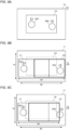
- FIGS. 9A to 9C are diagrams for explaining specific examples of total cutout range limitation processing performed by the image processing device 20 according to the first and third embodiments.
- the cutout position determination unit 27 sets the cutout position C0 at the center of the frame F0 by default.
- the object detection unit 23 detects the first object OB1 and the second object OB2 as objects of interest in the frame F0.
- the object tracking unit 24 starts tracking the first object OB1 and the second object OB2.
- the first object OB1 is moving to the left and the second object OB2 is moving to the right.
- the image capturing unit 10 is moving upward due to the camera shake of the photographer.
- the cutout position determination unit 27 moves the cutout position C0 of the reference frame F0 according to the composite vector of the correction vector for camera shake and the motion vector of the first object OB1 and determines a cutout position C1 for the first object OB1 in the current frame F1. In the same manner, the cutout position determination unit 27 moves the cutout position C0 of the reference frame F0 according to the composite vector of the correction vector for camera shake and the motion vector of the second object OB2 and determines a cutout position C2 for the second object OB2 in the current frame F1.
- the width W1 of the total cutout range before combining the cutout position C1 for the first object OB1 and the cutout position C2 for the second object OB2 is widened.
- both the first object OB1 and the second object OB2 are completely within the angle of view in the composite image.
- an image is generated in which the first object OB1 and the second object OB2 are closer than the actual distance regarding their positional relationship, and the deviation from the actual positional relationship increases.
- a limitation is set to the total cutout range. More specifically, an upper width limit Wt and an upper height limit Ht are set to the total cutout range.
- the vector strength adjustment unit 26 adjusts the strength of at least one of the motion vectors of the multiple objects such that the objects fit into the limited total cutout range.
- the vector strength adjustment unit 26 weakens the strength of the motion vector of the second object OB2 to satisfy the upper width limit Wt of the total cutout range. More specifically, the vector strength adjustment unit 26 weakens the strength of the motion vector of the second object OB2 such that the width W1' of the total cutout range before combining the cutout position C1 for the first object OB1 and the cutout position C2' for the second object OB2 is equal to the upper width limit Wt of the total cutout range. In this case, a part of the second object OB2 is removed from the angle of view in the composite image.
- the vector strength adjustment unit 26 may weaken the strength of the motion vector of the first object OB1 instead of the strength of the motion vector of the second object OB2 or may weaken the strength of both the motion vector of the first object OB1 and the motion vector of the second object OB2.
- the object for which the strength of the motion vector is weakened may be a low priority object.
- the priority may be set higher as the size of an object becomes larger.
- the priority may be set higher as an object becomes closer to the center of the frame.
- the priority may be set higher as an object becomes closer from the image capturing unit 10.
- the priority may be set higher as the motion of an object becomes smaller. A combination of these criteria may also be used.
- the setting of the values of the upper width limit Wt and the upper height limit Ht of the total cutout range may be changeable by the user.
- the larger the values of the upper width limit Wt and the upper height limit Ht are set the higher the probability that all the objects will fit into the angle of view in the composite image.
- the smaller the values of the upper width limit Wt and the upper height limit Ht are set the weaker the strength of the correction becomes, and the deviation from the actual compositional arrangement can thus be reduced.
- the third embodiment achieves the effects of both the first embodiment and the second embodiment.
- video with a natural compositional arrangement in the angle of view can be generated in which blurring is suppressed over the entire angle of view.
- the second embodiment can also be regarded as an example of a case where the subject is stationary in the third embodiment.
- FIGS. 9A-9C above explain an example in which multiple objects to be tracked are set in a frame.
- one or more of the multiple objects recognized in a frame may be set as objects to be tracked, and the remaining objects may be set as the objects not to be tracked.
- the objects not to be tracked are processed as the background.
- the first through third embodiments described above explain an example of generating a composite image by adjusting the angle of view for cutout in real time during image-capturing.
- video data of the entire image-capturing range and sensor information at each frame time may be recorded, and after the end of image-capturing, the recorded video data of the entire image-capturing range and the sensor information at each frame time may be read out, and the composite image generation processing according to the above-mentioned first through third embodiments may be executed.
- the composite image generation processing may be performed in a separate image playback device (e.g., PC or smartphone) instead of being performed in the image capturing device 1.
- the present invention is applicable to cameras equipped with an electronic image stabilization feature.
- image capturing device 10 image capturing unit, 11 vibration detection sensor, 12 distance detection sensor, 20 image processing device, 21 video acquisition unit, 22 image recognition unit, 23 object detection unit, 24 object tracking unit, 25 motion vector detection unit, 26 vector strength adjustment unit, 27
Landscapes
- Engineering & Computer Science (AREA)
- Multimedia (AREA)
- Signal Processing (AREA)
- Computer Vision & Pattern Recognition (AREA)
- Physics & Mathematics (AREA)
- General Physics & Mathematics (AREA)
- Theoretical Computer Science (AREA)
- Studio Devices (AREA)
- Image Analysis (AREA)
Applications Claiming Priority (2)
| Application Number | Priority Date | Filing Date | Title |
|---|---|---|---|
| JP2020156502A JP7418697B2 (ja) | 2020-09-17 | 2020-09-17 | 画像処理装置、及び画像処理プログラム |
| PCT/JP2021/020802 WO2022059265A1 (fr) | 2020-09-17 | 2021-06-01 | Dispositif de traitement d'image et programme de traitement d'image |
Publications (2)
| Publication Number | Publication Date |
|---|---|
| EP4216537A1 true EP4216537A1 (fr) | 2023-07-26 |
| EP4216537A4 EP4216537A4 (fr) | 2024-03-20 |
Family
ID=80775741
Family Applications (1)
| Application Number | Title | Priority Date | Filing Date |
|---|---|---|---|
| EP21868952.9A Pending EP4216537A4 (fr) | 2020-09-17 | 2021-06-01 | Dispositif de traitement d'image et programme de traitement d'image |
Country Status (5)
| Country | Link |
|---|---|
| US (1) | US12284438B2 (fr) |
| EP (1) | EP4216537A4 (fr) |
| JP (1) | JP7418697B2 (fr) |
| CN (1) | CN115804101B (fr) |
| WO (1) | WO2022059265A1 (fr) |
Families Citing this family (3)
| Publication number | Priority date | Publication date | Assignee | Title |
|---|---|---|---|---|
| CN114842031B (zh) * | 2022-05-12 | 2025-07-01 | 深圳市康冠商用科技有限公司 | 图像裁剪方法、装置、计算机设备及存储介质 |
| CN116193257B (zh) * | 2023-04-21 | 2023-09-22 | 成都华域天府数字科技有限公司 | 一种消除手术视频图像画面抖动的方法 |
| CN117690064B (zh) * | 2024-02-04 | 2024-04-16 | 广东电网有限责任公司广州供电局 | 输电线路检测方法、装置、电子设备和计算机可读介质 |
Family Cites Families (9)
| Publication number | Priority date | Publication date | Assignee | Title |
|---|---|---|---|---|
| CN1160210C (zh) * | 1999-09-20 | 2004-08-04 | 松下电器产业株式会社 | 驾驶提醒装置 |
| JP2007074031A (ja) * | 2005-09-02 | 2007-03-22 | Canon Inc | 撮像装置、及び、画像処理装置及び方法 |
| JP2009017223A (ja) * | 2007-07-04 | 2009-01-22 | Sony Corp | 撮影装置、画像処理装置、これらにおける画像処理方法およびプログラム |
| JP5111088B2 (ja) * | 2007-12-14 | 2012-12-26 | 三洋電機株式会社 | 撮像装置及び画像再生装置 |
| JP4832462B2 (ja) * | 2008-03-31 | 2011-12-07 | 富士通株式会社 | 画像処理装置、画像処理プログラムおよび画像処理方法 |
| JP5750864B2 (ja) * | 2010-10-27 | 2015-07-22 | ソニー株式会社 | 画像処理装置、画像処理方法、プログラム |
| JP6362473B2 (ja) | 2014-08-18 | 2018-07-25 | キヤノン株式会社 | 画像処理装置、撮像装置、画像処理方法、プログラム、記憶媒体 |
| JP6607764B2 (ja) * | 2015-11-04 | 2019-11-20 | 日立オートモティブシステムズ株式会社 | 撮像装置 |
| US11070729B2 (en) * | 2018-07-27 | 2021-07-20 | Canon Kabushiki Kaisha | Image processing apparatus capable of detecting moving objects, control method thereof, and image capture apparatus |
-
2020
- 2020-09-17 JP JP2020156502A patent/JP7418697B2/ja active Active
-
2021
- 2021-06-01 EP EP21868952.9A patent/EP4216537A4/fr active Pending
- 2021-06-01 WO PCT/JP2021/020802 patent/WO2022059265A1/fr not_active Ceased
- 2021-06-01 CN CN202180048380.4A patent/CN115804101B/zh active Active
-
2023
- 2023-03-10 US US18/182,220 patent/US12284438B2/en active Active
Also Published As
| Publication number | Publication date |
|---|---|
| JP2022050099A (ja) | 2022-03-30 |
| CN115804101B (zh) | 2025-09-19 |
| EP4216537A4 (fr) | 2024-03-20 |
| JP7418697B2 (ja) | 2024-01-22 |
| CN115804101A (zh) | 2023-03-14 |
| US20230283898A1 (en) | 2023-09-07 |
| WO2022059265A1 (fr) | 2022-03-24 |
| US12284438B2 (en) | 2025-04-22 |
Similar Documents
| Publication | Publication Date | Title |
|---|---|---|
| US12284438B2 (en) | Image processing device, image processing method and non-transitory computer-readable recording medium | |
| JP5049300B2 (ja) | 障害物検出表示装置 | |
| US9092875B2 (en) | Motion estimation apparatus, depth estimation apparatus, and motion estimation method | |
| JP4201809B2 (ja) | 手ぶれ補正装置及び方法並びに撮像装置 | |
| EP2330812B1 (fr) | Appareil de génération d'une image panoramique, procédé de génération d'une image panoramique et support lisible sur ordinateur | |
| JP5917054B2 (ja) | 撮像装置、画像データ処理方法、およびプログラム | |
| US20180376122A1 (en) | Application processor for disparity compensation between images of two cameras in digital photographing apparatus | |
| JP5725953B2 (ja) | 撮像装置及びその制御方法、並びに情報処理装置 | |
| JP5843454B2 (ja) | 画像処理装置、画像処理方法およびプログラム | |
| JP6577703B2 (ja) | 画像処理装置及び画像処理方法、プログラム、記憶媒体 | |
| JP5325800B2 (ja) | 画像処理装置、画像撮影装置、画像表示装置、およびプログラム | |
| JP2010114752A (ja) | 撮像装置及び撮像方法及びプログラム | |
| US20130033623A1 (en) | Imaging apparatus for correcting distortion in image captured using rolling shutter method and distortion correction method | |
| US12219252B2 (en) | Image processing device, image processing method and non-transitory computer-readable recording medium | |
| JP6012396B2 (ja) | 画像処理装置、画像処理方法およびプログラム。 | |
| JP2022161095A (ja) | 撮像制御装置、撮像制御方法およびプログラム | |
| JP6439412B2 (ja) | 画像処理装置および画像処理方法 | |
| JP6320165B2 (ja) | 画像処理装置及びその制御方法、並びにプログラム | |
| JP5891751B2 (ja) | 画像間差分装置および画像間差分方法 | |
| JP7814902B2 (ja) | 画像処理装置、撮像装置、画像処理装置の制御方法およびプログラム | |
| US20250157052A1 (en) | Image processing apparatus, image processing method, system, and non-transitory computer-readable storage medium | |
| JP6344903B2 (ja) | 画像処理装置およびその制御方法、撮像装置、プログラム |
Legal Events
| Date | Code | Title | Description |
|---|---|---|---|
| STAA | Information on the status of an ep patent application or granted ep patent |
Free format text: STATUS: THE INTERNATIONAL PUBLICATION HAS BEEN MADE |
|
| PUAI | Public reference made under article 153(3) epc to a published international application that has entered the european phase |
Free format text: ORIGINAL CODE: 0009012 |
|
| STAA | Information on the status of an ep patent application or granted ep patent |
Free format text: STATUS: REQUEST FOR EXAMINATION WAS MADE |
|
| 17P | Request for examination filed |
Effective date: 20230303 |
|
| AK | Designated contracting states |
Kind code of ref document: A1 Designated state(s): AL AT BE BG CH CY CZ DE DK EE ES FI FR GB GR HR HU IE IS IT LI LT LU LV MC MK MT NL NO PL PT RO RS SE SI SK SM TR |
|
| DAV | Request for validation of the european patent (deleted) | ||
| DAX | Request for extension of the european patent (deleted) | ||
| REG | Reference to a national code |
Ref country code: DE Ref legal event code: R079 Free format text: PREVIOUS MAIN CLASS: H04N0005232000 Ipc: G06T0007200000 |
|
| A4 | Supplementary search report drawn up and despatched |
Effective date: 20240219 |
|
| RIC1 | Information provided on ipc code assigned before grant |
Ipc: H04N 23/61 20230101ALI20240213BHEP Ipc: H04N 23/68 20230101ALI20240213BHEP Ipc: G06T 7/20 20170101AFI20240213BHEP |
|
| STAA | Information on the status of an ep patent application or granted ep patent |
Free format text: STATUS: EXAMINATION IS IN PROGRESS |
|
| 17Q | First examination report despatched |
Effective date: 20241022 |
|
| GRAP | Despatch of communication of intention to grant a patent |
Free format text: ORIGINAL CODE: EPIDOSNIGR1 |
|
| STAA | Information on the status of an ep patent application or granted ep patent |
Free format text: STATUS: GRANT OF PATENT IS INTENDED |
|
| INTG | Intention to grant announced |
Effective date: 20260130 |