EP4216619A1 - Communication sur liaison latérale - Google Patents
Communication sur liaison latérale Download PDFInfo
- Publication number
- EP4216619A1 EP4216619A1 EP21869752.2A EP21869752A EP4216619A1 EP 4216619 A1 EP4216619 A1 EP 4216619A1 EP 21869752 A EP21869752 A EP 21869752A EP 4216619 A1 EP4216619 A1 EP 4216619A1
- Authority
- EP
- European Patent Office
- Prior art keywords
- syncref
- predefined
- drop rate
- reference source
- communication
- Prior art date
- Legal status (The legal status is an assumption and is not a legal conclusion. Google has not performed a legal analysis and makes no representation as to the accuracy of the status listed.)
- Pending
Links
Images




Classifications
-
- H—ELECTRICITY
- H04—ELECTRIC COMMUNICATION TECHNIQUE
- H04W—WIRELESS COMMUNICATION NETWORKS
- H04W56/00—Synchronisation arrangements
- H04W56/001—Synchronization between nodes
- H04W56/0015—Synchronization between nodes one node acting as a reference for the others
-
- H—ELECTRICITY
- H04—ELECTRIC COMMUNICATION TECHNIQUE
- H04W—WIRELESS COMMUNICATION NETWORKS
- H04W16/00—Network planning, e.g. coverage or traffic planning tools; Network deployment, e.g. resource partitioning or cells structures
- H04W16/24—Cell structures
- H04W16/28—Cell structures using beam steering
-
- H—ELECTRICITY
- H04—ELECTRIC COMMUNICATION TECHNIQUE
- H04B—TRANSMISSION
- H04B7/00—Radio transmission systems, i.e. using radiation field
- H04B7/02—Diversity systems; Multi-antenna system, i.e. transmission or reception using multiple antennas
- H04B7/04—Diversity systems; Multi-antenna system, i.e. transmission or reception using multiple antennas using two or more spaced independent antennas
- H04B7/08—Diversity systems; Multi-antenna system, i.e. transmission or reception using multiple antennas using two or more spaced independent antennas at the receiving station
- H04B7/0868—Hybrid systems, i.e. switching and combining
- H04B7/088—Hybrid systems, i.e. switching and combining using beam selection
-
- H—ELECTRICITY
- H04—ELECTRIC COMMUNICATION TECHNIQUE
- H04W—WIRELESS COMMUNICATION NETWORKS
- H04W4/00—Services specially adapted for wireless communication networks; Facilities therefor
- H04W4/30—Services specially adapted for particular environments, situations or purposes
- H04W4/40—Services specially adapted for particular environments, situations or purposes for vehicles, e.g. vehicle-to-pedestrians [V2P]
- H04W4/44—Services specially adapted for particular environments, situations or purposes for vehicles, e.g. vehicle-to-pedestrians [V2P] for communication between vehicles and infrastructures, e.g. vehicle-to-cloud [V2C] or vehicle-to-home [V2H]
-
- H—ELECTRICITY
- H04—ELECTRIC COMMUNICATION TECHNIQUE
- H04W—WIRELESS COMMUNICATION NETWORKS
- H04W92/00—Interfaces specially adapted for wireless communication networks
- H04W92/16—Interfaces between hierarchically similar devices
- H04W92/18—Interfaces between hierarchically similar devices between terminal devices
Definitions
- the present disclosure relates to mobile communication.
- 3rd generation partnership project (3GPP) long-term evolution (LTE) is a technology for enabling high-speed packet communications.
- 3GPP 3rd generation partnership project
- LTE long-term evolution
- Many schemes have been proposed for the LTE objective including those that aim to reduce user and provider costs, improve service quality, and expand and improve coverage and system capacity.
- the 3GPP LTE requires reduced cost per bit, increased service availability, flexible use of a frequency band, a simple structure, an open interface, and adequate power consumption of a terminal as an upper-level requirement.
- ITU international telecommunication union
- NR new radio
- 3GPP has to identify and develop the technology components needed for successfully standardizing the new RAT timely satisfying both the urgent market needs, and the more long-term requirements set forth by the ITU radio communication sector (ITU-R) international mobile telecommunications (IMT)-2020 process.
- ITU-R ITU radio communication sector
- IMT international mobile telecommunications
- the NR should be able to use any spectrum band ranging at least up to 100 GHz that may be made available for wireless communications even in a more distant future.
- the NR targets a single technical framework addressing all usage scenarios, requirements and deployment scenarios including enhanced mobile broadband (eMBB), massive machine-type-communications (mMTC), ultra-reliable and low latency communications (URLLC), etc.
- eMBB enhanced mobile broadband
- mMTC massive machine-type-communications
- URLLC ultra-reliable and low latency communications
- the NR shall be inherently forward compatible.
- SL communication is a communication scheme in which a direct link is established between User Equipments (UEs), and the UEs exchange voice and data directly with each other without intervention of a base station (BS).
- UEs User Equipments
- BS base station
- SL communication is under consideration as a solution to the overhead of a BS caused by rapidly increasing data traffic.
- An NR terminal performing SL communication must be able to select or reselect a synchronization reference source.
- a terminal supporting Frequency Range 2 (FR2) SL communication may perform a beam management operation.
- FR2 SL communication Frequency Range 2
- one disclosure of the present specification provides a method for a UE to perform sidelink communication.
- the method includes transmitting a SL signal; and detecting another LTE based on a SL Synchronization Signal (SLSS) transmitted from the other UE during a predefined detection time.
- SLSS SL Synchronization Signal
- the UE includes at least one transceiver; at least one processor; and at least one memory that stores instructions and is operatively electrically connectable with the at least one processor.
- the operations performed based on the instructions being executed by the at least one processor may include: transmitting the SL signal; and detecting another UE based on a SL Synchronization Signal (SLSS) transmitted from the other UE during a predefined detection time.
- SLSS SL Synchronization Signal
- the device includes at least one processor; and at least one memory that stores instructions and is operably electrically connectable with the at least one processor, wherein operations performed based on the instructions being executed by the at least one processor, may include: transmitting the SL signal; and detecting another UE based on a SL Synchronization Signal (SLSS) transmitted from the other UE during a predefined detection time.
- SLSS SL Synchronization Signal
- one disclosure of the present specification provides a non-volatile (non-volatile) computer readable storage medium recording instructions.
- the instructions when executed by one or more processors, cause the one or more processors to perform operations comprising: transmitting the SL signal; and detecting another UE based on a SL Synchronization Signal (SLSS) transmitted from the other UE during a predefined detection time.
- SLSS SL Synchronization Signal
- CDMA code division multiple access
- FDMA frequency division multiple access
- TDMA time division multiple access
- OFDMA orthogonal frequency division multiple access
- SC-FDMA single carrier frequency division multiple access
- MC-FDMA multicarrier frequency division multiple access
- CDMA may be embodied through radio technology such as universal terrestrial radio access (UTRA) or CDMA2000.
- TDMA may be embodied through radio technology such as global system for mobile communications (GSM), general packet radio service (GPRS), or enhanced data rates for GSM evolution (EDGE).
- GSM global system for mobile communications
- GPRS general packet radio service
- EDGE enhanced data rates for GSM evolution
- OFDMA may be embodied through radio technology such as institute of electrical and electronics engineers (IEEE) 802.11 (Wi-Fi), IEEE 802.16 (WiMAX), IEEE 802.20, or evolved UTRA (E-UTRA).
- IEEE institute of electrical and electronics engineers
- Wi-Fi Wi-Fi
- WiMAX IEEE 802.16
- E-UTRA evolved UTRA
- UTRA is a part of a universal mobile telecommunications system (UMTS).
- 3rd generation partnership project (3GPP) long term evolution (LTE) is a part of evolved UMTS (E-UMTS) using E-UTRA.
- 3GPP LTE employs OFDMA in DL and SC-FDMA in UL.
- Evolution of 3GPP LTE includes LTE-A (advanced), LTE-A Pro, and/or 5G NR (new radio).
- implementations of the present disclosure are mainly described in regards to a 3GPP based wireless communication system.
- the technical features of the present disclosure are not limited thereto.
- the following detailed description is given based on a mobile communication system corresponding to a 3GPP based wireless communication system, aspects of the present disclosure that are not limited to 3GPP based wireless communication system are applicable to other mobile communication systems.
- a or B may mean “only A”, “only B”, or “both A and B”.
- a or B in the present disclosure may be interpreted as “A and/or B”.
- A, B or C in the present disclosure may mean “only A”, “only B”, “only C”, or "any combination of A, B and C”.
- slash (/) or comma (,) may mean “and/or”.
- A/B may mean “A and/or B”.
- A/B may mean "only A”, “only B”, or “both A and B”.
- A, B, C may mean "A, B or C”.
- At least one of A and B may mean “only A”, “only B” or “both A and B”.
- the expression “at least one of A or B” or “at least one of A and/or B” in the present disclosure may be interpreted as same as “at least one of A and B”.
- At least one of A, B and C may mean “only A”, “only B”, “only C”, or “any combination of A, B and C”.
- at least one of A, B or C or “at least one of A, B and/or C” may mean “at least one of A, B and C”.
- parentheses used in the present disclosure may mean “for example”.
- control information PDCCH
- PDCCH control information
- PDCCH control information
- PDCCH control information
- a User Equipment is shown in an exemplary manner, however, the shown UE may also be referred to as a term such as a Terminal, a Mobile Equipment (ME), and the like. Furthermore, the UE may be not only a portable device such as a notebook, a mobile phone, a PDA, a smart phone, a multimedia device, and the like, but also a non-portable device such as a PC and a vehicle mounted device.
- a LTE is used as an example of a wireless communication device (or wireless apparatus or a wireless device) for which wireless communication is available.
- the operation performed by a UE may be performed by a wireless communication device.
- the wireless communication device may also be referred to as a wireless apparatus or a wireless device.
- an AMF may mean an AMF node
- an SMF may mean an SMF node
- a UPF may mean a UPF node.
- base station used below may be referred to as a fixed station that communicates with a wireless device, generally, and may also be called a different term such as an evolved-NodeB (eNodeB), an evolved-NodeB (eNB), a Base Transceiver System (BTS), an Access Point, a Next generation NodeB (gNB), and the like.
- eNodeB evolved-NodeB
- eNB evolved-NodeB
- BTS Base Transceiver System
- gNB Next generation NodeB
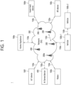
- FIG. 1 shows an example of a communication system to which implementations of the present disclosure is applied.
- the 5G usage scenarios shown in FIG. 1 are only exemplary, and the technical features of the present disclosure can be applied to other 5G usage scenarios which are not shown in FIG. 1 .
- Three main requirement categories for 5G include (1) a category of enhanced mobile broadband (eMBB), (2) a category of massive machine type communication (mMTC), and (3) a category of ultra-reliable and low latency communications (URLLC).
- eMBB enhanced mobile broadband
- mMTC massive machine type communication
- URLLC ultra-reliable and low latency communications
- Partial use cases may require a plurality of categories for optimization and other use cases may focus only upon one key performance indicator (KPI).
- KPI key performance indicator
- the communication system 1 includes wireless devices 100a to 100f, base stations (BSs) 200, and a network 300.
- FIG. 1 illustrates a 5G network as an example of the network of the communication system 1, the implementations of the present disclosure are not limited to the 5G system, and can be applied to the future communication system beyond the 5G system
- the BSs 200 and the network 300 may be implemented as wireless devices and a specific wireless device may operate as a BS/network node with respect to other wireless devices.
- the wireless devices 100a to 100f represent devices performing communication using radio access technology (RAT) (e.g., 5G new RAT (NR)) or LTE) and may be referred to as communication/radio/SG devices.
- RAT radio access technology
- the wireless devices 100a to 100f may include, without being limited to, a robot 100a, vehicles 100b-1 and 100b-2, an extended reality (XR) device 100c, a hand-held device 100d, a home appliance 100e, an IoT device 100f, and an artificial intelligence (AI) device/server 400.
- the vehicles may include a vehicle having a wireless communication function, an autonomous driving vehicle, and a vehicle capable of performing communication between vehicles.
- the vehicles may include an unmanned aerial vehicle (UAV) (e.g., a drone).
- UAV unmanned aerial vehicle
- the XR device may include an AR/VR/Mixed Reality (MR) device and may be implemented in the form of a head-mounted device (HMD), a head-up display (HUD) mounted in a vehicle, a television, a smartphone, a computer, a wearable device, a home appliance device, a digital signage, a vehicle, a robot, etc.
- the hand-held device may include a smartphone, a smartpad, a wearable device (e.g., a smartwatch or a smartglasses), and a computer (e.g., a notebook).
- the home appliance may include a TV, a refrigerator, and a washing machine.
- the IoT device may include a sensor and a smartmeter.
- the wireless devices 100a to 100f may be called user equipments (LTEs).
- LTE may include, for example, a cellular phone, a smartphone, a laptop computer, a digital broadcast terminal, a personal digital assistant (PDA), a portable multimedia player (PMP), a navigation system, a slate personal computer (PC), a tablet PC, an ultrabook, a vehicle, a vehicle having an autonomous traveling function, a connected car, an UAV, an AI module, a robot, an AR device, a VR device, an MR device, a hologram device, a public safety device, an MTC device, an IoT device, a medical device, a FinTech device (or a financial device), a security device, a weather/environment device, a device related to a 5G service, or a device related to a fourth industrial revolution field.
- PDA personal digital assistant
- PMP portable multimedia player
- PC slate personal computer
- tablet PC a tablet PC
- ultrabook a vehicle, a vehicle having an autonomous
- the UAV may be, for example, an aircraft aviated by a wireless control signal without a human being onboard.
- the VR device may include, for example, a device for implementing an object or a background of the virtual world.
- the AR device may include, for example, a device implemented by connecting an object or a background of the virtual world to an object or a background of the real world.
- the MR device may include, for example, a device implemented by merging an object or a background of the virtual world into an object or a background of the real world.
- the hologram device may include, for example, a device for implementing a stereoscopic image of 360 degrees by recording and reproducing stereoscopic information, using an interference phenomenon of light generated when two laser lights called holography meet.
- the public safety device may include, for example, an image relay device or an image device that is wearable on the body of a user.
- the MTC device and the IoT device may be, for example, devices that do not require direct human intervention or manipulation.
- the MTC device and the IoT device may include smartmeters, vending machines, thermometers, smartbulbs, door locks, or various sensors.
- the medical device may be, for example, a device used for the purpose of diagnosing, treating, relieving, curing, or preventing disease.
- the medical device may be a device used for the purpose of diagnosing, treating, relieving, or correcting injury or impairment.
- the medical device may be a device used for the purpose of inspecting, replacing, or modifying a structure or a function.
- the medical device may be a device used for the purpose of adjusting pregnancy.
- the medical device may include a device for treatment, a device for operation, a device for (in vitro) diagnosis, a hearing aid, or a device for procedure.
- the security device may be, for example, a device installed to prevent a danger that may arise and to maintain safety.
- the security device may be a camera, a closed-circuit TV (CCTV), a recorder, or a black box.
- CCTV closed-circuit TV
- the FinTech device may be, for example, a device capable of providing a financial service such as mobile payment.
- the FinTech device may include a payment device or a point of sales (POS) system.
- POS point of sales
- the weather/environment device may include, for example, a device for monitoring or predicting a weather/environment.
- the wireless devices 100a to 100f may be connected to the network 300 via the BSs 200.
- An AI technology may be applied to the wireless devices 100a to 100f and the wireless devices 100a to 100f may be connected to the AI server 400 via the network 300.
- the network 300 may be configured using a 3G network, a 4G (e.g., LTE) network, a 5G (e.g., NR) network, and a beyond-5G network.
- the wireless devices 100a to 100f may communicate with each other through the BSs 200/network 300, the wireless devices 100a to 100f may perform direct communication (e.g., sidelink communication) with each other without passing through the BSs 200/network 300.
- the vehicles 100b-1 and 100b-2 may perform direct communication (e.g., vehicle-to-vehicle (V2V)/vehicle-to-everything (V2X) communication).
- the IoT device e.g., a sensor
- the IoT device may perform direct communication with other IoT devices (e.g., sensors) or other wireless devices 100a to 100f.
- Wireless communication/connections 150a, 150b and 150c may be established between the wireless devices 100a to 100f and/or between wireless device 100a to 100f and BS 200 and/or between BSs 200.
- the wireless communication/connections may be established through various RATs (e.g., 5GNR) such as uplink/downlink communication 150a, sidelink communication (or device-to-device (D2D) communication) 150b, inter-base station communication 150c (e.g., relay, integrated access and backhaul (IAB)), etc.
- the wireless devices 100a to 100f and the BSs 200/the wireless devices 100a to 100f may transmit/receive radio signals to/from each other through the wireless communication/connections 150a, 150b and 150c.
- the wireless communication/connections 150a, 150b and 150c may transmit/receive signals through various physical channels.
- various configuration information configuring processes e.g., channel encoding/decoding, modulation/demodulation, and resource mapping/de-mapping
- resource allocating processes for transmitting/receiving radio signals, may be performed based on the various proposals of the present disclosure.
- AI refers to the field of studying artificial intelligence or the methodology that can create it
- machine learning refers to the field of defining various problems addressed in the field of AI and the field of methodology to solve them.
- Machine learning is also defined as an algorithm that increases the performance of a task through steady experience on a task.
- Robot means a machine that automatically processes or operates a given task by its own ability.
- robots with the ability to recognize the environment and make self-determination to perform actions can be called intelligent robots.
- Robots can be classified as industrial, medical, home, military, etc., depending on the purpose or area of use.
- the robot can perform a variety of physical operations, such as moving the robot joints with actuators or motors.
- the movable robot also includes wheels, brakes, propellers, etc., on the drive, allowing it to drive on the ground or fly in the air.
- Autonomous driving means a technology that drives on its own, and autonomous vehicles mean vehicles that drive without user's control or with minimal user's control.
- autonomous driving may include maintaining lanes in motion, automatically adjusting speed such as adaptive cruise control, automatic driving along a set route, and automatically setting a route when a destination is set.
- the vehicle covers vehicles equipped with internal combustion engines, hybrid vehicles equipped with internal combustion engines and electric motors, and electric vehicles equipped with electric motors, and may include trains, motorcycles, etc., as well as cars.
- Autonomous vehicles can be seen as robots with autonomous driving functions.
- VR technology provides objects and backgrounds of real world only through computer graphic (CG) images.
- AR technology provides a virtual CG image on top of a real object image.
- MR technology is a CG technology that combines and combines virtual objects into the real world.
- MR technology is similar to AR technology in that they show real and virtual objects together. However, there is a difference in that in AR technology, virtual objects are used as complementary forms to real objects, while in MR technology, virtual objects and real objects are used as equal personalities.
- NR supports multiples numerologies (and/or multiple subcarrier spacings (SCS)) to support various 5G services. For example, if SCS is 15 kHz, wide area can be supported in traditional cellular bands, and if SCS is 30 kHz/60 kHz, dense-urban, lower latency, and wider carrier bandwidth can be supported. If SCS is 60 kHz or higher, bandwidths greater than 24.25 GHz can be supported to overcome phase noise.
- numerologies and/or multiple subcarrier spacings (SCS)
- the NR frequency band may be defined as two types of frequency range, i.e., FR1 and FR2.
- the numerical value of the frequency range may be changed.
- the frequency ranges of the two types may be as shown in Table 1 below.
- FR1 may mean "sub 6 GHz range”
- FR2 may mean "above 6 GHz range”
- mmW millimeter wave
- FR1 may include a frequency band of 410MHz to 7125MHz as shown in Table 2 below. That is, FR1 may include a frequency band of 6GHz (or 5850, 5900, 5925 MHz, etc.) or more. For example, a frequency band of 6 GHz (or 5850, 5900, 5925 MHz, etc.) or more included in FR1 may include an unlicensed band. Unlicensed bands may be used for a variety of purposes, for example for communication for vehicles (e.g., autonomous driving). [Table 2] Frequency Range designation Corresponding frequency range Subcarrier Spacing FR1 410MHz - 7125MHz 15, 30, 60kHz FR2 24250MHz - 52600MHz 60, 120, 240kHz
- the radio communication technologies implemented in the wireless devices in the present disclosure may include narrowband internet-of-things (NB-IoT) technology for low-power communication as well as LTE, NR and 6G.
- NB-IoT technology may be an example of low power wide area network (LPWAN) technology, may be implemented in specifications such as LTE Cat NB1 and/or LTE Cat NB2, and may not be limited to the above-mentioned names.
- LPWAN low power wide area network
- the radio communication technologies implemented in the wireless devices in the present disclosure may communicate based on LTE-M technology.
- LTE-M technology may be an example of LPWAN technology and be called by various names such as enhanced machine type communication (eMTC).
- eMTC enhanced machine type communication
- LTE-M technology may be implemented in at least one of the various specifications, such as 1) LTE Cat 0, 2) LTE Cat M1, 3) LTE Cat M2, 4) LTE non-bandwidth limited (non-BL), 5) LTE-MTC, 6) LTE Machine Type Communication, and/or 7) LTE M, and may not be limited to the above-mentioned names.
- the radio communication technologies implemented in the wireless devices in the present disclosure may include at least one of ZigBee, Bluetooth, and/or LPWAN which take into account low-power communication, and may not be limited to the above-mentioned names.
- ZigBee technology may generate personal area networks (PANs) associated with small/low-power digital communication based on various specifications such as IEEE 802.15.4 and may be called various names.
- PANs personal area networks
- FIG. 2 shows an example of wireless devices to which implementations of the present disclosure is applied.
- a first wireless device 100 and a second wireless device 200 may transmit/receive radio signals to/from an external device through a variety of RATs (e.g., LTE and NR).
- RATs e.g., LTE and NR
- ⁇ the first wireless device 100 and the second wireless device 200 ⁇ may correspond to at least one of ⁇ the wireless device 100a to 100f and the BS 200 ⁇ , ⁇ the wireless device 100a to 100f and the wireless device 100a to 100f ⁇ and/or ⁇ the BS 200 and the BS 200 ⁇ of FIG. 1 .
- the first wireless device 100 may include at least one transceiver, such as a transceiver 106, at least one processing chip, such as a processing chip 101, and/or one or more antennas 108.
- a transceiver such as a transceiver 106
- a processing chip such as a processing chip 101
- antennas 108 one or more antennas 108.
- the processing chip 101 may include at least one processor, such a processor 102, and at least one memory, such as a memory 104. It is exemplarily shown in FIG. 2 that the memory 104 is included in the processing chip 101. Additional and/or alternatively, the memory 104 may be placed outside of the processing chip 101.
- the processor 102 may control the memory 104 and/or the transceiver 106 and may be configured to implement the descriptions, functions, procedures, suggestions, methods and/or operational flowcharts described in the present disclosure. For example, the processor 102 may process information within the memory 104 to generate first information/signals and then transmit radio signals including the first information/signals through the transceiver 106. The processor 102 may receive radio signals including second information/signals through the transceiver 106 and then store information obtained by processing the second information/signals in the memory 104.
- the memory 104 may be operably connectable to the processor 102.
- the memory 104 may store various types of information and/or instructions.
- the memory 104 may store a software code 105 which implements instructions that, when executed by the processor 102, perform the descriptions, functions, procedures, suggestions, methods and/or operational flowcharts disclosed in the present disclosure.
- the software code 105 may implement instructions that, when executed by the processor 102, perform the descriptions, functions, procedures, suggestions, methods and/or operational flowcharts disclosed in the present disclosure.
- the software code 105 may control the processor 102 to perform one or more protocols.
- the software code 105 may control the processor 102 to perform one or more layers of the radio interface protocol.
- the processor 102 and the memory 104 may be a part of a communication modem/circuit/chip designed to implement RAT (e.g., LTE or NR).
- the transceiver 106 may be connected to the processor 102 and transmit and/or receive radio signals through one or more antennas 108.
- Each of the transceiver 106 may include a transmitter and/or a receiver.
- the transceiver 106 may be interchangeably used with radio frequency (RF) unit(s).
- the first wireless device 100 may represent a communication modem/circuit/chip.
- the second wireless device 200 may include at least one transceiver, such as a transceiver 206, at least one processing chip, such as a processing chip 201, and/or one or more antennas 208.
- the processing chip 201 may include at least one processor, such a processor 202, and at least one memory, such as a memory 204. It is exemplarily shown in FIG. 2 that the memory 204 is included in the processing chip 201. Additional and/or alternatively, the memory 204 may be placed outside of the processing chip 201.
- the processor 202 may control the memory 204 and/or the transceiver 206 and may be configured to implement the descriptions, functions, procedures, suggestions, methods and/or operational flowcharts described in the present disclosure. For example, the processor 202 may process information within the memory 204 to generate third information/signals and then transmit radio signals including the third information/signals through the transceiver 206. The processor 202 may receive radio signals including fourth information/signals through the transceiver 106 and then store information obtained by processing the fourth information/signals in the memory 204.
- the memory 204 may be operably connectable to the processor 202.
- the memory 204 may store various types of information and/or instructions.
- the memory 204 may store a software code 205 which implements instructions that, when executed by the processor 202, perform the descriptions, functions, procedures, suggestions, methods and/or operational flowcharts disclosed in the present disclosure.
- the software code 205 may implement instructions that, when executed by the processor 202, perform the descriptions, functions, procedures, suggestions, methods and/or operational flowcharts disclosed in the present disclosure.
- the software code 205 may control the processor 202 to perform one or more protocols.
- the software code 205 may control the processor 202 to perform one or more layers of the radio interface protocol.
- the processor 202 and the memory 204 may be a part of a communication modem/circuit/chip designed to implement RAT (e.g., LTE or NR).
- the transceiver 206 may be connected to the processor 202 and transmit and/or receive radio signals through one or more antennas 208.
- Each of the transceiver 206 may include a transmitter and/or a receiver.
- the transceiver 206 may be interchangeably used with RF unit.
- the second wireless device 200 may represent a communication modem/circuit/chip.
- One or more protocol layers may be implemented by, without being limited to, one or more processors 102 and 202.
- the one or more processors 102 and 202 may implement one or more layers (e.g., functional layers such as physical (PHY) layer, media access control (MAC) layer, radio link control (RLC) layer, packet data convergence protocol (PDCP) layer, radio resource control (RRC) layer, and service data adaptation protocol (SDAP) layer).
- layers e.g., functional layers such as physical (PHY) layer, media access control (MAC) layer, radio link control (RLC) layer, packet data convergence protocol (PDCP) layer, radio resource control (RRC) layer, and service data adaptation protocol (SDAP) layer).
- PHY physical
- MAC media access control
- RLC radio link control
- PDCP packet data convergence protocol
- RRC radio resource control
- SDAP service data adaptation protocol
- the one or more processors 102 and 202 may generate one or more protocol data units (PDUs) and/or one or more service data unit (SDUs) according to the descriptions, functions, procedures, suggestions, methods and/or operational flowcharts disclosed in the present disclosure.
- the one or more processors 102 and 202 may generate messages, control information, data, or information according to the descriptions, functions, procedures, suggestions, methods and/or operational flowcharts disclosed in the present disclosure.
- the one or more processors 102 and 202 may generate signals (e.g., baseband signals) including PDUs, SDUs, messages, control information, data, or information according to the descriptions, functions, procedures, suggestions, methods and/or operational flowcharts disclosed in the present disclosure and provide the generated signals to the one or more transceivers 106 and 206.
- the one or more processors 102 and 202 may receive the signals (e.g., baseband signals) from the one or more transceivers 106 and 206 and acquire the PDUs, SDUs, messages, control information, data, or information according to the descriptions, functions, procedures, suggestions, methods and/or operational flowcharts disclosed in the present disclosure.
- the one or more processors 102 and 202 may be referred to as controllers, microcontrollers, microprocessors, or microcomputers.
- the one or more processors 102 and 202 may be implemented by hardware, firmware, software, or a combination thereof.
- ASICs application specific integrated circuits
- DSPs digital signal processors
- DSPDs digital signal processing devices
- PLDs programmable logic devices
- FPGAs field programmable gate arrays
- the descriptions, functions, procedures, suggestions, methods and/or operational flowcharts disclosed in the present disclosure may be implemented using firmware or software and the firmware or software may be configured to include the modules, procedures, or functions.
- Firmware or software configured to perform the descriptions, functions, procedures, suggestions, methods and/or operational flowcharts disclosed in the present disclosure may be included in the one or more processors 102 and 202 or stored in the one or more memories 104 and 204 so as to be driven by the one or more processors 102 and 202.
- the descriptions, functions, procedures, suggestions, methods and/or operational flowcharts disclosed in the present disclosure may be implemented using firmware or software in the form of code, commands, and/or a set of commands.
- the one or more memories 104 and 204 may be connected to the one or more processors 102 and 202 and store various types of data, signals, messages, information, programs, code, instructions, and/or commands.
- the one or more memories 104 and 204 may be configured by read-only memories (ROMs), random access memories (RAMs), electrically erasable programmable read-only memories (EPROMs), flash memories, hard drives, registers, cash memories, computer-readable storage media, and/or combinations thereof.
- the one or more memories 104 and 204 may be located at the interior and/or exterior of the one or more processors 102 and 202.
- the one or more memories 104 and 204 may be connected to the one or more processors 102 and 202 through various technologies such as wired or wireless connection.
- the one or more transceivers 106 and 206 may transmit user data, control information, and/or radio signals/channels, mentioned in the descriptions, functions, procedures, suggestions, methods and/or operational flowcharts disclosed in the present disclosure, to one or more other devices.
- the one or more transceivers 106 and 206 may receive user data, control information, and/or radio signals/channels, mentioned in the descriptions, functions, procedures, suggestions, methods and/or operational flowcharts disclosed in the present disclosure, from one or more other devices.
- the one or more transceivers 106 and 206 may be connected to the one or more processors 102 and 202 and transmit and receive radio signals.
- the one or more processors 102 and 202 may perform control so that the one or more transceivers 106 and 206 may transmit user data, control information, or radio signals to one or more other devices.
- the one or more processors 102 and 202 may perform control so that the one or more transceivers 106 and 206 may receive user data, control information, or radio signals from one or more other devices.
- the one or more transceivers 106 and 206 may be connected to the one or more antennas 108 and 208 and the one or more transceivers 106 and 206 may be configured to transmit and receive user data, control information, and/or radio signals/channels, mentioned in the descriptions, functions, procedures, suggestions, methods and/or operational flowcharts disclosed in the present disclosure, through the one or more antennas 108 and 208.
- the one or more antennas 108 and 208 may be a plurality of physical antennas or a plurality of logical antennas (e.g., antenna ports).
- the one or more transceivers 106 and 206 may convert received user data, control information, radio signals/channels, etc., from RF band signals into baseband signals in order to process received user data, control information, radio signals/channels, etc., using the one or more processors 102 and 202.
- the one or more transceivers 106 and 206 may convert the user data, control information, radio signals/channels, etc., processed using the one or more processors 102 and 202 from the base band signals into the RF band signals.
- the one or more transceivers 106 and 206 may include (analog) oscillators and/or filters.
- the one or more transceivers 106 and 206 can up-convert OFDM baseband signals to OFDM signals by their (analog) oscillators and/or filters under the control of the one or more processors 102 and 202 and transmit the up-converted OFDM signals at the carrier frequency.
- the one or more transceivers 106 and 206 may receive OFDM signals at a carrier frequency and down-convert the OFDM signals into OFDM baseband signals by their (analog) oscillators and/or filters under the control of the one or more processors 102 and 202.
- a UE may operate as a transmitting device in uplink (LTL) and as a receiving device in downlink (DL).
- a BS may operate as a receiving device in UL and as a transmitting device in DL.
- the first wireless device 100 acts as the UE
- the second wireless device 200 acts as the BS.
- the processor(s) 102 connected to, mounted on or launched in the first wireless device 100 may be configured to perform the UE behavior according to an implementation of the present disclosure or control the transceiver(s) 106 to perform the LTE behavior according to an implementation of the present disclosure.
- the processor(s) 202 connected to, mounted on or launched in the second wireless device 200 may be configured to perform the BS behavior according to an implementation of the present disclosure or control the transceiver(s) 206 to perform the BS behavior according to an implementation of the present disclosure.
- a BS is also referred to as a node B (NB), an eNode B (eNB), or a gNB.
- NB node B
- eNB eNode B
- gNB gNode B
- FIG. 3 shows an example of a wireless device to which implementations of the present disclosure is applied.
- the wireless device may be implemented in various forms according to a use-case/service (refer to FIG. 1 ).
- wireless devices 100 and 200 may correspond to the wireless devices 100 and 200 of FIG. 2 and may be configured by various elements, components, units/portions, and/or modules.
- each of the wireless devices 100 and 200 may include a communication unit 110, a control unit 120, a memory unit 130, and additional components 140.
- the communication unit 110 may include a communication circuit 112 and transceiver(s) 114.
- the communication circuit 112 may include the one or more processors 102 and 202 of FIG. 2 and/or the one or more memories 104 and 204 of FIG. 2 .
- the transceiver(s) 114 may include the one or more transceivers 106 and 206 of FIG.
- the control unit 120 is electrically connected to the communication unit 110, the memory unit 130, and the additional components 140 and controls overall operation of each of the wireless devices 100 and 200.
- the control unit 120 may control an electric/mechanical operation of each of the wireless devices 100 and 200 based on programs/code/commands/information stored in the memory unit 130.
- the control unit 120 may transmit the information stored in the memory unit 130 to the exterior (e.g., other communication devices) via the communication unit 110 through a wireless/wired interface or store, in the memory unit 130, information received through the wireless/wired interface from the exterior (e.g., other communication devices) via the communication unit 110.
- the additional components 140 may be variously configured according to types of the wireless devices 100 and 200.
- the additional components 140 may include at least one of a power unit/battery, input/output (I/O) unit (e.g., audio I/O port, video I/O port), a driving unit, and a computing unit.
- the wireless devices 100 and 200 may be implemented in the form of, without being limited to, the robot (100a of FIG. 1 ), the vehicles (100b-1 and 100b-2 of FIG. 1 ), the XR device (100c of FIG. 1 ), the hand-held device (100d of FIG. 1 ), the home appliance (100e of FIG. 1 ), the IoT device (100f of FIG.
- the wireless devices 100 and 200 may be used in a mobile or fixed place according to a use-example/service.
- the entirety of the various elements, components, units/portions, and/or modules in the wireless devices 100 and 200 may be connected to each other through a wired interface or at least a part thereof may be wirelessly connected through the communication unit 110.
- the control unit 120 and the communication unit 110 may be connected by wire and the control unit 120 and first units (e.g., 130 and 140) may be wirelessly connected through the communication unit 110.
- Each element, component, unit/portion, and/or module within the wireless devices 100 and 200 may further include one or more elements.
- the control unit 120 may be configured by a set of one or more processors.
- control unit 120 may be configured by a set of a communication control processor, an application processor (AP), an electronic control unit (ECU), a graphical processing unit, and a memory control processor.
- memory unit 130 may be configured by a RAM, a DRAM, a ROM, a flash memory, a volatile memory, a non-volatile memory, and/or a combination thereof.
- FIG. 4 illustrates an example of a structure of an NR system to which the implementation of the present disclosure is applied.
- FIG. 4 shows a structure of an NR system, in accordance with an embodiment of the present disclosure.
- the embodiment of FIG. 4 may be combined with various embodiments of the present disclosure.
- a radio frame may be used for performing uplink and downlink transmission.
- a radio frame has a length of 10 ms and may be defined to be configured of two half-frames (HFs).
- a half-frame may include five 1 ms subframes (SFs).
- a subframe (SF) may be divided into one or more slots, and the number of slots within a subframe may be determined in accordance with subcarrier spacing (SCS).
- SCS subcarrier spacing
- Each slot may include 12 or 14 OFDM(A) symbols according to a cyclic prefix (CP).
- CP cyclic prefix
- each slot may include 14 symbols.
- each slot may include 12 symbols.
- a symbol may include an OFDM symbol (or CP-OFDM symbol) and a Single Carrier-FDMA (SC-FDMA) symbol (or Discrete Fourier Transform-spread-OFDM (DFT-s-OFDM) symbol).
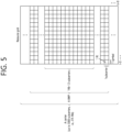
- FIG. 5 illustrates an example of a structure of a slot of an NR system to which the implementation of the present disclosure is applied.
- FIG. 5 shows a structure of a slot of an NR frame, in accordance with an embodiment of the present disclosure.
- the embodiment of FIG. 5 may be combined with various embodiments of the present disclosure.
- a slot includes a plurality of symbols in a time domain.
- one slot may include 14 symbols.
- one slot may include 12 symbols.
- one slot may include 7 symbols.
- one slot may include 6 symbols.
- a carrier includes a plurality of subcarriers in a frequency domain.
- a Resource Block (RB) may be defined as a plurality of consecutive subcarriers (e.g., 12 subcarriers) in the frequency domain.
- a Bandwidth Part (BWP) may be defined as a plurality of consecutive (Physical) Resource Blocks ((P)RBs) in the frequency domain, and the BWP may correspond to one type of numerology (e.g., SCS, CP length, etc.).
- a carrier may include a maximum of N BWPs (e.g., 5 BWPs). Data communication may be performed via an activated BWP.
- Each element may be referred to as a Resource Element (RE) within a resource grid and one complex symbol may be mapped to each element.
- RE Resource Element
- a radio interface between a UE and another UE or a radio interface between the UE and a network may consist of an L1 layer, an L2 layer, and an L3 layer.
- the L1 layer may imply a physical layer.
- the L2 layer may imply at least one of a MAC layer, an RLC layer, a PDCP layer, and an SDAP layer.
- the L3 layer may imply an RRC layer.
- V2X or SL communication will be described.
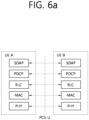
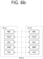
- FIGS. 6a and 6b illustrate an example of a radio protocol architecture for a SL communication to which the implementation of the present disclosure is applied.
- FIG. 6a and FIG. 6b show a radio protocol architecture for a SL communication, in accordance with an embodiment of the present disclosure.
- the embodiment of FIG. 6a and FIG. 6b may be combined with various embodiments of the present disclosure. More specifically, FIG. 6a shows a user plane protocol stack, and FIG. 6b shows a control plane protocol stack.
- SLSS sidelink synchronization signal
- the SLSS may include a primary sidelink synchronization signal (PSSS) and a secondary sidelink synchronization signal (SSSS), as an SL-specific sequence.
- PSSS primary sidelink synchronization signal
- SSSS secondary sidelink synchronization signal
- the PSSS may be referred to as a sidelink primary synchronization signal (S-PSS)
- S-SSS sidelink secondary synchronization signal
- S-SSS sidelink secondary synchronization signal
- length-127 M-sequences may be used for the S-PSS
- length-127 gold sequences may be used for the S-SSS.
- a LTE may use the S-PSS for initial signal detection and for synchronization acquisition.
- the LTE may use the S-PSS and the S-SSS for acquisition of detailed synchronization and for detection of a synchronization signal ID.
- a physical sidelink broadcast channel may be a (broadcast) channel for transmitting default (system) information which needs to be first known by the UE before SL signal transmission/reception.
- the default information may be information related to SLSS, a duplex mode (DM), a time division duplex (TDD) uplink/downlink (LTL/DL) configuration, information related to a resource pool, a type of an application related to the SLSS, a subframe offset, broadcast information, or the like.
- DM duplex mode
- TDD time division duplex
- LNL/DL uplink/downlink
- a payload size of the PSBCH may be 56 bits including 24-bit CRC.
- the S-PSS, the S-SSS, and the PSBCH may be included in a block format (e.g., SL synchronization signal (SS)/PSBCH block, hereinafter, sidelink-synchronization signal block (S-SSB)) supporting periodical transmission.
- the S-SSB may have the same numerology (i.e., SCS and CP length) as a physical sidelink control channel (PSCCH)/physical sidelink shared channel (PSSCH) in a carrier, and a transmission bandwidth may exist within a (pre-)configured sidelink (SL) BWP.
- the S-SSB may have a bandwidth of 11 resource blocks (RBs).
- the PSBCH may exist across 11 RBs.
- a frequency position of the S-SSB may be (pre-)configured. Accordingly, the UE does not have to perform hypothesis detection at frequency to discover the S-SSB in the carrier.
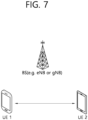
- FIG. 7 illustrates an example of a LTE performing V2X or SL communication to which the implementation of the present disclosure is applied.
- FIG. 7 shows a UE performing V2X or SL communication, in accordance with an embodiment of the present disclosure.
- the embodiment of FIG. 7 may be combined with various embodiments of the present disclosure.
- the term "terminal" may generally imply a UE of a user.
- the BS may also be regarded as a sort of the UE.
- a UE 1 may be a first apparatus 100
- a UE 2 may be a second apparatus 200.
- the UE 1 may select a resource unit corresponding to a specific resource in a resource pool which implies a set of series of resources.
- the UE 1 may transmit an SL signal by using the resource unit.
- a resource pool in which the UE 1 is capable of transmitting a signal may be configured to the UE 2 which is a receiving UE, and the signal of the LTE 1 may be detected in the resource pool.
- the BS may inform the LTE 1 of the resource pool.
- another UE may inform the UE 1 of the resource pool, or the LTE 1 may use a pre-configured resource pool.
- the resource pool may be configured in units of a plurality of resources, and each UE may select a unit of one or a plurality of resources to use it in SL signal transmission thereof.
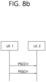
- FIGS. 8a and 8b illustrate an example of a procedure of performing V2X or SL communication by a UE based on a transmission mode to which the implementation of the present disclosure is applied.
- FIG. 8a and FIG. 8b show a procedure of performing V2X or SL communication by a UE based on a transmission mode, in accordance with an embodiment of the present disclosure.
- the embodiment of FIG. 8a and FIG. 8b may be combined with various embodiments of the present disclosure.
- the transmission mode may be called a mode or a resource allocation mode.
- the transmission mode may be called an LTE transmission mode.
- the transmission mode may be called an NR resource allocation mode.
- FIG. 8a shows a LTE operation related to an LTE transmission mode 1 or an LTE transmission mode 3.
- FIG. 8a shows a LTE operation related to an NR resource allocation mode 1.
- the LTE transmission mode 1 may be applied to general SL communication
- the LTE transmission mode 3 may be applied to V2X communication.
- FIG. 8b shows a LTE operation related to an LTE transmission mode 2 or an LTE transmission mode 4.
- FIG. 8b shows a LTE operation related to an NR resource allocation mode 2.
- a BS may schedule an SL resource to be used by the UE for SL transmission.
- the BS may perform resource scheduling to a UE 1 through a PDCCH (more specifically, downlink control information (DCI)), and the UE 1 may perform V2X or SL communication with respect to a UE 2 according to the resource scheduling.
- the UE 1 may transmit a sidelink control information (SCI) to the UE 2 through a physical sidelink control channel (PSCCH), and thereafter transmit data based on the SCI to the UE 2 through a physical sidelink shared channel (PSSCH).
- SCI sidelink control information
- PSCCH physical sidelink control channel
- PSSCH physical sidelink shared channel
- the UE may determine an SL transmission resource within an SL resource configured by a BS/network or a pre-configured SL resource.
- the configured SL resource or the pre-configured SL resource may be a resource pool.
- the LTE may autonomously select or schedule a resource for SL transmission.
- the UE may perform SL communication by autonomously selecting a resource within a configured resource pool.
- the UE may autonomously select a resource within a selective window by performing a sensing and resource (re)selection procedure.
- the sensing may be performed in units of subchannels.
- the UE 1 which has autonomously selected the resource within the resource pool may transmit the SCI to the UE 2 through a PSCCH, and thereafter may transmit data based on the SCI to the LTE 2 through a PSSCH.
- Table 3 represents an example of an operating band used for V2X (or SL) communication.
- Operating Band V2X Operating Band V2X LTE transmit V2X UE receive Duplex Mode Interface F UL_low - F UL_high F DL_low - F DL_high 47 47 5855 MHz - 5925 MHz 5855 MHz - 5925 MHz HD(Half Duplex) PCS 39 39 1880 MHz - 1920MHz 1880 MHz - 1920MHz TDD PCS and/or Uu
- an operating band 47 according to the example of Table 3 is used for E-UTRA V2X (or SL) communication
- the operating band 47 may be referred to as B47.
- the operating band 47 according to the example of Table 3 is used for NR V2X (or SL) communication
- the operating band 47 may be referred to as n47.
- an operating band 39 according to the example of Table 3 is used for E-UTRA V2X (or SL) communication
- the operating band 39 may be referred to as B39.
- the operating band 39 according to the example of Table 3 is used for NR V2X (or SL) communication
- the operating band 39 may be referred to as n39.
- At least one proposal scheme proposed according to various embodiments of the present disclosure may be applied to not only sidelink communication or V2X communication based on a PCS interface or an SL interface (e.g., PSCCH, PSSCH, PSBCH, PSSS/SSSS, etc.), but also sidelink communication or V2X communication based on a Uu interface (e.g., PUSCH, PDSCH, PDCCH, PUCCH, etc.).
- a PCS interface or an SL interface e.g., PSCCH, PSSCH, PSBCH, PSSS/SSSS, etc.
- a Uu interface e.g., PUSCH, PDSCH, PDCCH, PUCCH, etc.
- a receiving operation of a LTE may include a decoding operation and/or a receiving operation of a sidelink channel and/or a sidelink signal (e.g., PSCCH, PSSCH, PSFCH, PSBCH, PSSS/SSSS, etc.).
- a transmitting operation of a UE may include a transmitting operation of a sidelink channel and/or a sidelink signal (e.g., PSCCH, PSSCH, PSFCH, PSBCH, PSSS/SSSS, etc.).
- a (physical) channel used for an RX LTE to transmit at least one of the following information to a TX UE may be referred to as PSFCH.
- a Uu channel may include a UL channel and/or a DL channel.
- the UL channel may include PUSCH, PUCCH, and the like.
- the DL channel may include PDCCH, PDSCH, and the like.
- an SL channel may include PSCCH, PSSCH, PSFCH, PSBCH, and the like.
- sidelink (SL), V2X, V2X sidelink (SL) may have the same meaning.
- An NR terminal performing SL communication must be able to select or reselect a synchronization reference source.
- a terminal supporting Frequency Range 2 (FR2) SL communication may perform a beam management operation.
- FR2 SL communication Frequency Range 2
- the disclosure herein describes operations related to selection and reselection of a synchronization reference source in NR SL communication.
- Selection/Reselection-related operations for synchronization reference sources of NR SLs e.g., FR1 NR SL, FR2 NR SL
- NR SLs e.g., FR1 NR SL, FR2 NR SL
- the disclosure of the present specification proposes an operation of selecting a synchronization reference source for a terminal supporting FR2 Sidelink (SL).
- SL Sidelink
- the terminal supporting SL may stop its own SLSS transmission or data transmission operation and perform an operation of detecting (receiving) the SLSS of the SyncRef UE.
- the allowable transmission drop rate is explained as an example below for the FR1 NR SL terminal and the FR2 NR SL terminal.
- the first example of the disclosure of the present specification proposes an operation of a terminal supporting FR1 NR SL communication with reference to various examples.
- the content described in the first example of the disclosure of the present specification can be applied to sidelink communication.
- the contents described in the first example of the disclosure of the present specification may be applied to sidelink services, NR V2X, Public Safety, Device to Device (D2D), commercial use cases, and the like.
- SLSS sidelink synchronization signal
- a terminal supporting FR1 SL communication may detect (or detect) a SyncRef UE.
- a SyncRef UE may be considered detectable for the following examples:
- the LTE may perform the following actions:
- the synchronization reference source of a SyncRef UE may also be GNSS.
- the UE may not drop the NR SLSS and NR SL data transmissions because it may already be synchronized with the SyncRef UE.
- the UE may perform the following actions:
- the UE may drop up to 30% of the LTE's SLSS transmissions during T detect,SyncRef UE_SL to select/reselect the synchronization reference source to SyncRef.
- the LTE may perform the following operations:
- the UE may perform operations such as the following examples:
- the UE must be able to perform S-RSRP measurements for the identified three intra-frequency NR SL SyncRef.
- the LTE must be able to perform PSBCH-RSRP measurements for SyncRef UEs within the identified three frequencies with a measurement period of 320 ms. It is assumed that the SyncRef UE does not drop or delay SLSS transmission within the measurement period. Otherwise, the measurement period may be extended.
- the UE may evaluate the GNSS synchronization source reliability for at least 20 seconds before changing the synchronization reference from GNSS to another synchronization reference source. While the UE performs reliability evaluation of the GNSS synchronization source, the LTE should always synchronize directly to GNSS.
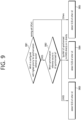
- FIG. 9 shows an example of an operation of a terminal according to a first example of the disclosure of the present specification.
- an operation for selecting and/or reselecting an N SL synchronization reference source may be performed according to the example of FIG. 9 .
- FIG. 9 shows an example of an operation of a terminal according to a first example of the disclosure of the present specification.
- the content shown in FIG. 9 is only an example, and the scope of the disclosure of the present specification is not limited by FIG. 9 .
- the terminal is not limited by the example of FIG. 9 and may perform operations according to the first example of the present disclosure described through various examples above.
- the terminal may determine which synchronization reference source is set to the highest priority.
- the synchronization reference source set to the highest priority may be a serving cell (PCell) or GNSS.
- the terminal may perform step S905.
- the terminal may perform step S902.
- the terminal may determine what synchronization reference source the terminal is synchronized with.
- the synchronization reference source to which the UE is synchronized may be GNSS, a SyncRef UE synchronized directly or indirectly with GNSS, or other case (e.g., i-1-c) in other case).
- the other case may include a case where the reference source with which the UE is synchronized is a SyncRef UE or a serving cell (PCell) that is not directly or indirectly synchronized with GNSS.
- PCell serving cell
- the terminal may detect an SL signal (e.g., SLSS) of other UE.
- the terminal may perform an operation according to "i-1-a) when the UE is directly synchronized with the GNSSS" described above.
- the LTE may not drop NR SLSS and NR SL data transmissions to select/reselect the synchronization reference source to SyncRef UE.
- the UE may detect an SL signal (e.g., SLSS) of another UE.
- the terminal may perform an operation according to "i-1-b) when the UE is directly or indirectly synchronized with the SyncRef LTE synchronized with the GNSS" described above.
- the UE should not drop NR SL data transmission to select/reselect the synchronization reference source to SyncRef UE.
- the UE must be able to identify a newly detectable intra frequency SyncRef UE within the detection time (e.g. T detect, SyncRef UE_SL seconds) if the SyncRef LTE meets the selection/reselection criteria defined in TS 38.331.
- the LTE may detect the SL signal (e.g., SLSS) of the SyncRef UE within the detection time.
- T detect,SyncRef UE_SL can be defined as 1.6 seconds in SCH Es/Iot ⁇ 0dB.
- the UE may be allowed to drop up to 30% of the SLSS transmission of the UE during T detect,SyncRef UE_SL .
- the UE may detect an SL signal (e.g., SLSS) of another UE.
- the terminal may perform an operation according to "i-1-c) in other case" or Case 1-2 described above.
- the LTE may drop NR SLSS and NR SL data transmissions to select/reselect the synchronization reference source to SyncRef LTE.
- the LTE must be able to identify a newly detectable intra frequency SyncRef UE within the detection time (e.g. T detect, SyncRef UE_SL seconds) if the SyncRef UE meets the selection/reselection criteria defined in TS 38.331.
- the UE may detect the SL signal (e.g., SLSS) of the SyncRef UE within the detection time.
- T detect,SyncRef UE_SL can be defined as 8 seconds in SCH Es/Iot ⁇ 0dB.
- the LTE may be allowed to drop up to 6% of the NR SL data transmission and NR SLSS transmission of the UE during T detect,SyncRef UE_SL .
- the LTE may drop NR SL data reception per PSBCH monitoring occasion up to 2 slots.
- the overall drop rate should not exceed 0.3% of NR SL data reception during T detect,SyncRef UE_SL for selection/reselection of SyncRef UE.
- the second example of the disclosure of the present specification refers to various examples, and proposes an operation of a terminal supporting FR2 NR SL communication.
- the content described in the second example of the disclosure of the present specification can be applied to sidelink communication.
- the content described in the second example of the disclosure of the present specification can be applied to Sidelink services, NR V2X, Public Safety, Device to Device (D2D), commercial use cases, and the like.
- FR2 SL beam management may or may not be applied to the operation of the terminal.
- the operation of the terminal according to the case where FR2 SL beam management is applied and the case where FR2 SL beam management is not applied will be described.
- a time to detect the sidelink synchronization signal (SLSS) of the FR2 SyncRef UE (e.g., T detect, SyncRef UE_SL ) may need to be defined based on the LTE's beam operation. And based on this, in order to detect the SLSS of the FR2 SyncRef UE, a drop rate at which the terminal does not transmit its own SLSS or data may be determined.
- SLSS sidelink synchronization signal
- SLSS sidelink synchronization signal
- a SyncRef UE may be considered detectable in the following example:
- the example of Table 4 may be an example of a side condition that must be satisfied for the PSBCH-RSRP measured by the UE.
- a LTE may measure PSBCH-RSRP based on a PSBCH received from another LTE.
- ⁇ s/Iot may mean a received SINR (Signal to ⁇ Noise and Interference ⁇ Ratio).
- Absolute Accuracy may mean the absolute accuracy of the measured RSRP. For example, absolute accuracy can be expressed as measured RSRP lute accuracy.
- Relative Accuracy may mean the relative accuracy of the measured RSRP, represented by the maximum value among 95%-50% and 5%-50% of the measured RSRP Cumulative Distribution Function (CDF).
- CDF Cumulative Distribution Function
- ⁇ s/Iot may mean SINR when measuring PSBCH-RSRP.
- the normal condition may mean, for example, when the temperature of the terminal is +15 to +35 degrees.
- Extreme condition may mean, for example, when the terminal temperature is -10 degrees to +55 degrees.
- the LTE may perform the following operations:
- the synchronization reference source of a SyncRef UE may also be GNSS.
- the UE may not drop the NR SLSS and NR SL data transmissions because it may already be synchronized with the SyncRef UE.
- the UE may perform the following operations:
- X1 may be an example of a detection time considering the number of beams operated by a terminal supporting FR2 SL communication.
- Y1 may be an example of a maximum drop rate considering the number of beams operated by a terminal supporting FR2 SL communication.
- FR2 SL terminal when a terminal supporting FR2 SL communication (hereinafter also referred to as "FR2 SL terminal") performs SL communication, for SLSS detection, the number of beams of the used UE may be considered.
- T detect,SyncRef UE_SL T detect,SyncRef UE_SL of FR1 SyncRef UE
- maximum drop rate 30%
- it is proposed to be 1.6 seconds (10 times the S-SSB period 160 ms x 10).
- the period of the S-SSB may be 160 ms.
- N 4 to 8
- the maximum drop rate Y1 may be 30%.
- the maximum drop rate of 30% means that a maximum of 3 samples are required to detect SLSS. If the maximum drop rate is changed, the sample interval for detecting up to three samples may be changed. For example, when the maximum drop rate is increased to 50%, a maximum of 6 sample intervals must be secured to ensure that 3 samples are 50% based on the S-SSB cycle of 160 ms. In other words, if the terminal drops up to 50% in a 6-sample interval, 3 samples can be guaranteed.
- T detect and SyncRef UE_SL of FR2 SyncRef UE are proposed as follows for each maximum drop rate.
- X1 may be calculated as (6.4 to 12.8) * 30/Y1.
- X1 may be 3.84 seconds to 7.68 seconds. As an example, 5.76 seconds is suggested.
- Y1 60%
- T detect and SyncRef UE_SL X1 may be 3.2 seconds to 6.4 seconds. As an example, 4.8 seconds is suggested.
- T detect and SyncRef UE_SL , X1 may be 2.56 seconds to 5.12 seconds. As an example, 3.84 seconds is suggested.
- T detect and SyncRef UE_SL X1 may be 1.92 seconds to 3.84 seconds. As an example, 2.88 seconds is suggested.
- GNSS is set to the highest priority, in cases other than the two cases (e.g., "ii-1-a) LTE synchronized directly to GNSSS" and "ii-1-b) LTE synchronized directly or indirectly to SyncRef UE synchronized to GNSS") described in the above example, the LTE may perform the following operations:
- X2 may be an example of a detection time considering the number of beams operated by a terminal supporting FR2 SL communication.
- Y2 and Y3 may be examples of maximum drop rates considering the number of beams operated by a terminal supporting FR2 SL communication.
- Y2 may be the maximum drop rate at which the LTE drops NR SL data transmission and NR SLSS transmission.
- Y3 may be the maximum drop rate at which the LTE drops NR SL data reception.
- T detect,SyncRef UE_SL T detect,SyncRef UE_SL of FR1 SyncRef LTE
- the period of the S-SSB may be 160 ms.
- T detect,SyncRef UE_SL Tdetect, SyncRef UE_SL of FR2 SyncRef LTE
- N 4 to 8
- T detect,SyncRef UE_SL , X2 32 seconds ⁇ 64 seconds is suggested.
- T detect,SyncRef UE_SL 48 seconds.
- T detect SynchronizationRef UE_SL of FR2 SyncRef LTE are proposed as follows for each maximum drop rate.
- X2 may be calculated as (32 ⁇ 64)*6/Y2.
- the UE may perform actions such as the following examples:
- X2 may be an example of a detection time considering the number of beams operated by a terminal supporting FR2 SL communication.
- Y2 and Y3 may be examples of maximum drop rates considering the number of beams operated by a terminal supporting FR2 SL communication.
- Y2 may be the maximum drop rate at which the LTE drops NR SL data transmission and NR SLSS transmission.
- Y3 may be the maximum drop rate at which the LTE drops NR SL data reception.
- T detect,SyncRef UE_SL T detect,SyncRef UE_SL of FR1 SyncRef LTE
- the period of the S-SSB may be 160 ms.
- T detect,SyncRef UE_SL Tdetect, SyncRef LTE SL of FR2 SyncRef LTE
- N 4 to 8
- T detect,SyncRef UE_SL , X2 32 seconds ⁇ 64 seconds is suggested.
- T detect,syncRef UE_SL 48 seconds.
- T detect,syncRef UE_SL of FR2 SyncRef LTE are proposed as follows for each maximum drop rate.
- M (M ⁇ 2) or more SLSSs are basically configured in the S-SSB.
- M or more SLSSs may be included in the S-SSB.
- X1 and X2 can be reduced by M times while maintaining the same Y1%, Y2%, and Y3%.
- the detection time and maximum drop rate may be suggested as in the following example.
- SL beam management may not be applied to a terminal supporting FR2 SL communication.
- a terminal supporting FR2 SL communication may operate in the same manner as described in Case 1.
- the terminal specifications supporting FR1 NR SL of Case 1, Case1-1 and Case1-2 may be applied.
- FIG. 10 shows an example of an operation of a terminal according to a second example of the disclosure of the present specification.
- an operation for selecting and/or reselecting an NS SL synchronization reference source may be performed according to the example of FIG. 10 .
- FIG. 10 shows an example of an operation of a terminal according to a second example of the disclosure of the present specification.
- the content shown in FIG. 10 is only an example, and the scope of the disclosure of the present specification is not limited by FIG. 10 .
- the terminal is not limited by the example of FIG. 10 and may perform operations according to the second example of the present disclosure described through various examples above.
- step S1001 the terminal may determine whether the terminal supports SL beam management or whether the terminal performs SL beam management for SL communication. When the terminal supports SL beam management and/or performs SL beam management, the terminal may perform step S1002. If the terminal does not support SL beam management or does not perform SL beam management, the terminal may perform the same operation as described in the first example of the disclosure of the present specification. For example, in this case, the terminal may perform step S901 of FIG. 9 .
- the terminal may determine which synchronization reference source is set to the highest priority.
- the synchronization reference source set to the highest priority may be a serving cell (PCell) or GNSS.
- the terminal may perform step S1006.
- the terminal may perform step S1003.
- the terminal may determine what is the synchronization reference source to which the terminal is synchronized.
- the synchronization reference source to which the UE is synchronized may be GNSS, a SyncRef UE synchronized directly or indirectly to GNSS, or other case (eg ii-1-c) in other case).
- other case may include a case where the reference source with which the LTE is synchronized is a SyncRef UE or a serving cell (PCell) that is not directly or indirectly synchronized with GNSS.
- the terminal may detect an SL signal (e.g., SLSS) of another UE.
- the terminal may perform an operation according to "ii-1-a) when the UE is directly synchronized with the GNSS" described above.
- the LTE may not drop NR SLSS and NR SL data transmissions to select/reselect the synchronization reference source to SyncRef LTE.
- the LTE may not perform an operation of detecting a signal to select/reselect the synchronization reference source as the SyncRef UE.
- the UE may detect an SL signal (e.g., SLSS) of another UE.
- the terminal may perform an operation according to "ii-1-b) when the LTE is directly or indirectly synchronized with a SyncRef LTE synchronized with GNSS" described above. For example, the UE should not drop NR SL data transmission to select/reselect the synchronization reference source to SyncRef UE.
- the LTE must be able to identify a newly detectable intra frequency SyncRef UE within the detection time (e.g., T detect, SyncRef UE_SL seconds).
- the UE may detect the SL signal (e.g., SLSS) of the SyncRef UE within the detection time.
- T detect,SyncRef UE_SL can be defined as X1 seconds at SCH Es/Iot ⁇ 0dB.
- the UE may drop up to Y1% of the LTE's SLSS transmissions during T detect,SyncRef UE_SL to select/reselect the synchronization reference source to SyncRef.
- X1 and Y1 may be set as described in various examples of "ii-1-b) when the UE is directly or indirectly synchronized with a SyncRef UE synchronized with GNSS".
- N 4 to 8
- T detect,SyncRef UESL 6.4 seconds to 12.8 seconds.
- M (M ⁇ 2) or more SLSSs may be basically set in the S-SSB.
- X1 and Y1 may be defined as in the following example.
- ⁇ X1, Y1 ⁇ it can be defined as in the following example.
- ⁇ X1, Y1 ⁇ ⁇ 6.4-12.8, 30 ⁇ , ⁇ 3.84-7.68, 50 ⁇ , ⁇ 3.2-6.4, 60 ⁇ , ⁇ 2.56-5.12, 75 ⁇ , or ⁇ 1.92-3.84, 100 ⁇ .
- X1 and Y1 may be defined as in the following example.
- ⁇ X1, Y1 ⁇ ⁇ (6.4-12.8)/M, 30 ⁇ , ⁇ (3.84 ⁇ 7.68)/M, 50 ⁇ , ⁇ (3.2 ⁇ 6.4)/M, 60 ⁇ , ⁇ (2.56 ⁇ 5.12)/M, 75 ⁇ , or ⁇ (1.92-3.84)/M, 100 ⁇ .
- the terminal may detect an SL signal (e.g., SLSS) of another UE.
- the terminal may perform an operation according to "ii-1-c) in other case" or Case 2-2 described above.
- the LTE may drop NR SLSS and NR SL data transmissions to select/reselect the synchronization reference source to SyncRef UE. If the SyncRef UE meets the selection/reselection criteria defined in 3GPP TS 38.331 V16.1.0, the LTE must be able to identify a newly detectable intra frequency SyncRef UE within the detection time (e.g., T detect, SyncRef UE_SL seconds).
- the UE may detect the SL signal (e.g., SLSS) of the SyncRef UE within the detection time.
- T detect,SyncRef UE_SL may be defined as X2 seconds at SCH Es/Iot ⁇ 0dB.
- the LTE may be allowed to drop up to Y2% of the LTE's NR SL data transmission and NR SLSS transmission during T detect, SyncRef UE_SL .
- the UE can drop NR SL data reception per PSBCH monitoring occasion up to 2 slots. And, the overall drop rate must not exceed Y3% of NR SL data reception during T detect,SyncRef UE_SL for selection/reselection of SyncRef UE.
- X2, Y2, and Y3 may be set as described above in “ii-1-c) in other cases” or various examples of Case 2-2.
- N 4 to 8
- T detect,SyncRef UE_SL 32 seconds to 64 seconds is proposed.
- T detect,SyncRef UE_SL 48 seconds.
- Y3 0.3%.
- M (M ⁇ 2) or more SLSSs may be basically set in the S-SSB.
- X2, Y2, and Y3 may be defined as in the following example. If the combination of X2, Y2, and Y3 is expressed as ⁇ X2, Y2, Y3 ⁇ , it can be defined as in the following example.
- ⁇ X2, Y2, Y3 ⁇ ⁇ (32 ⁇ 64)/M, 6, 0.3 ⁇ , ⁇ (19.2 ⁇ 38.4)/M, 10, 0.5 ⁇ , ⁇ (16 ⁇ 32)/M, 12, 0.6 ⁇ , ⁇ (12.8 ⁇ 25.6)/M, 15, 0.75 ⁇ , ⁇ (9.6 ⁇ 19.2)/M, 20, 1.0 ⁇ , or ⁇ (6.4 ⁇ 12.8)/M, 30, 1.5 ⁇ .
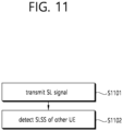
- FIG. 11 shows an example of an operation of a terminal according to an embodiment of the disclosure of the present specification.
- FIG. 11 shows an example of an operation of a terminal according to the disclosure of the present specification.
- the content shown in FIG. 11 is only an example, and the scope of the disclosure of the present specification is not limited by FIG. 11 .
- the terminal may perform operations according to various examples previously described in the disclosure of the present specification (e.g., the first example and the second example of the disclosure of the present specification).
- step S1101 the terminal may transmit an SL signal.
- the UE may detect the SLSS of another UE. For example, the UE may detect other UEs based on SLSS transmitted from other UEs during a predefined detection time.
- the SL signal may be allowed to drop up to a predefined maximum drop rate.
- a predefined maximum drop rate and a predefined detection time (e.g., T detect, SyncRef UE_SL seconds) may be set based on various examples described in the first and second examples of the disclosure of the present specification.
- the predefined maximum drop rate and the predefined detection time may be set based on the first synchronization reference source set to the highest priority and the second synchronization reference source with which the LTE is synchronized.
- the detection time (e.g., T detect, SyncRef UE_SL seconds) and the maximum drop rate may be set based on Case 1-1 and Case 1-2 described in the first example of the disclosure of the present specification, and Case 2-1 and Case 2-2 described in the second example of the disclosure of the present specification.
- an operation for a LTE supporting NR SL communication to select and/or reselect a synchronization reference source can be clearly defined. Accordingly, the NR UE can efficiently and/or clearly perform an operation for selecting and/or reselecting a synchronization reference source. According to what has been described in the disclosure of the present specification, SL communication can be efficiently performed. In addition, even when a terminal supporting FR2 SL communication performs a beam management operation, the terminal can efficiently perform SL communication.
- the operation of the UE described in the present disclosure may be performed by the device shown in FIG. 1 to FIG. 3 .
- the UE may be the first wireless device 100 or the second wireless device 200 shown in FIG. 1 .
- the operation of the UE described in the present disclosure may be processed by one or more processors 102 or 202.
- the operation of the UE described in the present disclosure may be stored in one or more memories 104 or 204 in the form of instruction/program (e.g., instruction, executable code, etc.) executable by the one or more processors 102 or 202.
- the one or more processors 102 or 202 may control the one or more memories 104 or 204 and the one or more transceivers 105 or 206 and may perform the operation of the UE described in the present disclosure by executing the instruction/program stored in the one or more memories 104 or 204.
- the instructions for performing the operation of the UE described in the present disclosure may be stored in a non-volatile computer readable storage medium.
- the storage medium may be included in the one or more memories 104 or 204.
- the instructions stored in the storage medium may be executed by the one or more processors 102 or 202, and the operation of the UE described in the present disclosure may be performed.
- the operation of the BS may be implemented by the device shown in FIG. 1 to FIG. 3 .
- the BS e.g., NG-RAN, gNB, gNB (NB-IoT), gNB (NR) eNB, RAN, etc.
- the BS e.g., NG-RAN, gNB, gNB (NB-IoT), gNB (NR) eNB, RAN, etc.
- the BS may be the first wireless device 100a or the second wireless device 100b shown in FIG. 1 .
- the operation of the BS e.g., NG-RAN, gNB, gNB (NB-IoT), gNB (NR) eNB, RAN, etc.
- the operation of the UE described in the present disclosure may be stored in one or more memories 104 or 204 in the form of instruction/program (e.g., instruction, executable code, etc.) executable by the one or more processors 102 or 202.
- instruction/program e.g., instruction, executable code, etc.
- the one or more processors 102 or 202 may control the one or more memories 104 or 204 and the one or more transceivers 105 or 206 and may perform the operation of the BS (e.g., NG-RAN, gNB, gNB (NB-IoT), gNB (NR) eNB, RAN, etc.) described in the present disclosure by executing the instruction/program stored in the one or more memories 104 or 204.
- the BS e.g., NG-RAN, gNB, gNB (NB-IoT), gNB (NR) eNB, RAN, etc.
- the instructions for performing the operation of the BS may be stored in a non-volatile (or non-transitory) computer readable storage medium.
- the storage medium may be included in the one or more memories 104 or 204.
- the instructions stored in the storage medium may be executed by the one or more processors 102 or 202, and the operation of the BS (e.g., NG-RAN, gNB, gNB (NB-IoT), gNB (NR) eNB, RAN, etc.) described in the present disclosure may be performed.
- the methods are described based on a flowchart as a series of steps or blocks. However, the methods are not limited to the order of the steps described above, and a certain step may be performed in a different order or performed simultaneously. Furthermore, it is understood that the steps shown in the flowchart are not mutually exclusive, but another step may be included, or one or more steps may be deleted without influencing the scope to those ordinary skilled in the art.
Landscapes
- Engineering & Computer Science (AREA)
- Computer Networks & Wireless Communication (AREA)
- Signal Processing (AREA)
- Mobile Radio Communication Systems (AREA)
- Databases & Information Systems (AREA)
Applications Claiming Priority (2)
| Application Number | Priority Date | Filing Date | Title |
|---|---|---|---|
| KR20200120190 | 2020-09-18 | ||
| PCT/KR2021/012715 WO2022060130A1 (fr) | 2020-09-18 | 2021-09-16 | Communication sur liaison latérale |
Publications (2)
| Publication Number | Publication Date |
|---|---|
| EP4216619A1 true EP4216619A1 (fr) | 2023-07-26 |
| EP4216619A4 EP4216619A4 (fr) | 2024-11-27 |
Family
ID=80776209
Family Applications (1)
| Application Number | Title | Priority Date | Filing Date |
|---|---|---|---|
| EP21869752.2A Pending EP4216619A4 (fr) | 2020-09-18 | 2021-09-16 | Communication sur liaison latérale |
Country Status (4)
| Country | Link |
|---|---|
| US (1) | US20230292266A1 (fr) |
| EP (1) | EP4216619A4 (fr) |
| KR (1) | KR20230043903A (fr) |
| WO (1) | WO2022060130A1 (fr) |
Families Citing this family (3)
| Publication number | Priority date | Publication date | Assignee | Title |
|---|---|---|---|---|
| US12177798B2 (en) * | 2021-10-08 | 2024-12-24 | Nokia Technologies Oy | Sidelink group coordination for group-specific synchronization reference |
| WO2024063599A1 (fr) * | 2022-09-23 | 2024-03-28 | 엘지전자 주식회사 | Procédé de synchronisation dans une communication de liaison latérale |
| CN118803530A (zh) * | 2023-04-14 | 2024-10-18 | 维沃移动通信有限公司 | 旁链路定位参考信号处理方法、装置、终端及存储介质 |
Family Cites Families (3)
| Publication number | Priority date | Publication date | Assignee | Title |
|---|---|---|---|---|
| CN109586879B (zh) * | 2017-09-28 | 2023-06-20 | 北京三星通信技术研究有限公司 | 多载波旁路通信同步源选择的方法及设备 |
| US10785735B2 (en) * | 2017-10-02 | 2020-09-22 | Apple Inc. | Vehicle to everything synchronization reference selection and reselection |
| US11540150B2 (en) * | 2018-01-19 | 2022-12-27 | Qualcomm Incorporated | Beam recovery procedure using a second component carrier |
-
2021
- 2021-09-16 EP EP21869752.2A patent/EP4216619A4/fr active Pending
- 2021-09-16 US US18/025,316 patent/US20230292266A1/en active Pending
- 2021-09-16 WO PCT/KR2021/012715 patent/WO2022060130A1/fr not_active Ceased
- 2021-09-16 KR KR1020237005791A patent/KR20230043903A/ko active Pending
Also Published As
| Publication number | Publication date |
|---|---|
| US20230292266A1 (en) | 2023-09-14 |
| KR20230043903A (ko) | 2023-03-31 |
| EP4216619A4 (fr) | 2024-11-27 |
| WO2022060130A1 (fr) | 2022-03-24 |
Similar Documents
| Publication | Publication Date | Title |
|---|---|---|
| US20240080694A1 (en) | Measurement based on measurement gap | |
| US20230379982A1 (en) | Method for efficiently transmitting sidelink csi report for beam management in mmwave v2x communication system | |
| US12610328B2 (en) | Maximum sensitivity degradation | |
| EP4319294A1 (fr) | Communications impliquant des ntn | |
| US11785592B2 (en) | Sidelink communication | |
| US12432704B2 (en) | Sidelink communication | |
| US11917665B2 (en) | Switching between uplink and sidelink | |
| US20230292266A1 (en) | Sidelink communication | |
| US12143868B2 (en) | Sidelink transmission in mobile communication involving switching between multiple V2X sidelink technologies | |
| US20230396975A1 (en) | Method for mmwave v2x communication in multiple ue communication environment, and device therefor | |
| US12127050B2 (en) | Systems and methods for performing sidelink communication involving multiple radio access technologies | |
| KR20230107678A (ko) | Ntn 위성의 ephemeris 정보 업데이트를 위한 ue의 동작 | |
| US12356381B2 (en) | Maximum sensitivity degradation for dual connectivity | |
| US12294533B2 (en) | Maximum sensitivity degradation for carrier aggregation | |
| KR20230003542A (ko) | Ntn을 위한 rrm 측정 설정 | |
| US20240008109A1 (en) | Method for rapidly recovering communication connection in sidelink communication and device for same | |
| US11967999B2 (en) | Sidelink communication | |
| EP4593479A1 (fr) | Procédé de synchronisation dans une communication de liaison latérale | |
| US12634851B2 (en) | Sidelink communication | |
| US12593294B2 (en) | Sidelink communication | |
| KR20230043902A (ko) | 사이드링크 통신 | |
| US12432590B2 (en) | Scheduling restriction and SMTC configuration for high frequency range |
Legal Events
| Date | Code | Title | Description |
|---|---|---|---|
| STAA | Information on the status of an ep patent application or granted ep patent |
Free format text: STATUS: THE INTERNATIONAL PUBLICATION HAS BEEN MADE |
|
| PUAI | Public reference made under article 153(3) epc to a published international application that has entered the european phase |
Free format text: ORIGINAL CODE: 0009012 |
|
| STAA | Information on the status of an ep patent application or granted ep patent |
Free format text: STATUS: REQUEST FOR EXAMINATION WAS MADE |
|
| 17P | Request for examination filed |
Effective date: 20230313 |
|
| AK | Designated contracting states |
Kind code of ref document: A1 Designated state(s): AL AT BE BG CH CY CZ DE DK EE ES FI FR GB GR HR HU IE IS IT LI LT LU LV MC MK MT NL NO PL PT RO RS SE SI SK SM TR |
|
| DAV | Request for validation of the european patent (deleted) | ||
| DAX | Request for extension of the european patent (deleted) | ||
| A4 | Supplementary search report drawn up and despatched |
Effective date: 20241030 |
|
| RIC1 | Information provided on ipc code assigned before grant |
Ipc: H04B 7/08 20060101ALI20241024BHEP Ipc: H04B 7/0408 20170101ALI20241024BHEP Ipc: H04W 4/40 20180101ALI20241024BHEP Ipc: H04W 92/18 20090101ALI20241024BHEP Ipc: H04W 56/00 20090101AFI20241024BHEP |