EP4217558B1 - Mehrfachrichtungstürschloss - Google Patents
Mehrfachrichtungstürschloss Download PDFInfo
- Publication number
- EP4217558B1 EP4217558B1 EP21873208.9A EP21873208A EP4217558B1 EP 4217558 B1 EP4217558 B1 EP 4217558B1 EP 21873208 A EP21873208 A EP 21873208A EP 4217558 B1 EP4217558 B1 EP 4217558B1
- Authority
- EP
- European Patent Office
- Prior art keywords
- door
- door lock
- housing
- orientation
- lock
- Prior art date
- Legal status (The legal status is an assumption and is not a legal conclusion. Google has not performed a legal analysis and makes no representation as to the accuracy of the status listed.)
- Active
Links
Images



Classifications
-
- E—FIXED CONSTRUCTIONS
- E05—LOCKS; KEYS; WINDOW OR DOOR FITTINGS; SAFES
- E05B—LOCKS; ACCESSORIES THEREFOR; HANDCUFFS
- E05B63/00—Locks or fastenings with special structural characteristics
- E05B63/04—Locks or fastenings with special structural characteristics for alternative use on the right-hand or left-hand side of wings
-
- E—FIXED CONSTRUCTIONS
- E05—LOCKS; KEYS; WINDOW OR DOOR FITTINGS; SAFES
- E05B—LOCKS; ACCESSORIES THEREFOR; HANDCUFFS
- E05B47/00—Operating or controlling locks or other fastening devices by electric or magnetic means
- E05B47/0001—Operating or controlling locks or other fastening devices by electric or magnetic means with electric actuators; Constructional features thereof
-
- E—FIXED CONSTRUCTIONS
- E05—LOCKS; KEYS; WINDOW OR DOOR FITTINGS; SAFES
- E05B—LOCKS; ACCESSORIES THEREFOR; HANDCUFFS
- E05B47/00—Operating or controlling locks or other fastening devices by electric or magnetic means
- E05B47/0001—Operating or controlling locks or other fastening devices by electric or magnetic means with electric actuators; Constructional features thereof
- E05B47/0012—Operating or controlling locks or other fastening devices by electric or magnetic means with electric actuators; Constructional features thereof with rotary electromotors
-
- E—FIXED CONSTRUCTIONS
- E05—LOCKS; KEYS; WINDOW OR DOOR FITTINGS; SAFES
- E05B—LOCKS; ACCESSORIES THEREFOR; HANDCUFFS
- E05B47/00—Operating or controlling locks or other fastening devices by electric or magnetic means
- E05B47/02—Movement of the bolt by electromagnetic means; Adaptation of locks, latches, or parts thereof, for movement of the bolt by electromagnetic means
-
- E—FIXED CONSTRUCTIONS
- E05—LOCKS; KEYS; WINDOW OR DOOR FITTINGS; SAFES
- E05B—LOCKS; ACCESSORIES THEREFOR; HANDCUFFS
- E05B9/00—Lock casings or latch-mechanism casings ; Fastening locks or fasteners or parts thereof to the wing
- E05B9/08—Fastening locks or fasteners or parts thereof, e.g. the casings of latch-bolt locks or cylinder locks to the wing
-
- G—PHYSICS
- G07—CHECKING-DEVICES
- G07C—TIME OR ATTENDANCE REGISTERS; REGISTERING OR INDICATING THE WORKING OF MACHINES; GENERATING RANDOM NUMBERS; VOTING OR LOTTERY APPARATUS; ARRANGEMENTS, SYSTEMS OR APPARATUS FOR CHECKING NOT PROVIDED FOR ELSEWHERE
- G07C9/00—Individual registration on entry or exit
- G07C9/00174—Electronically operated locks; Circuits therefor; Nonmechanical keys therefor, e.g. passive or active electrical keys or other data carriers without mechanical keys
- G07C9/00309—Electronically operated locks; Circuits therefor; Nonmechanical keys therefor, e.g. passive or active electrical keys or other data carriers without mechanical keys operated with bidirectional data transmission between data carrier and locks
-
- E—FIXED CONSTRUCTIONS
- E05—LOCKS; KEYS; WINDOW OR DOOR FITTINGS; SAFES
- E05B—LOCKS; ACCESSORIES THEREFOR; HANDCUFFS
- E05B45/00—Alarm locks
- E05B45/06—Electric alarm locks
- E05B2045/065—Switch or sensor type used in alarm locks
- E05B2045/0665—Magnetic switches, e.g. reed- or hall-switch
-
- E—FIXED CONSTRUCTIONS
- E05—LOCKS; KEYS; WINDOW OR DOOR FITTINGS; SAFES
- E05B—LOCKS; ACCESSORIES THEREFOR; HANDCUFFS
- E05B45/00—Alarm locks
- E05B45/06—Electric alarm locks
- E05B2045/065—Switch or sensor type used in alarm locks
- E05B2045/067—Switches triggered by inertia
-
- E—FIXED CONSTRUCTIONS
- E05—LOCKS; KEYS; WINDOW OR DOOR FITTINGS; SAFES
- E05B—LOCKS; ACCESSORIES THEREFOR; HANDCUFFS
- E05B47/00—Operating or controlling locks or other fastening devices by electric or magnetic means
- E05B47/0001—Operating or controlling locks or other fastening devices by electric or magnetic means with electric actuators; Constructional features thereof
- E05B2047/0014—Constructional features of actuators or power transmissions therefor
-
- E—FIXED CONSTRUCTIONS
- E05—LOCKS; KEYS; WINDOW OR DOOR FITTINGS; SAFES
- E05B—LOCKS; ACCESSORIES THEREFOR; HANDCUFFS
- E05B47/00—Operating or controlling locks or other fastening devices by electric or magnetic means
- E05B2047/0048—Circuits, feeding, monitoring
- E05B2047/0067—Monitoring
-
- E—FIXED CONSTRUCTIONS
- E05—LOCKS; KEYS; WINDOW OR DOOR FITTINGS; SAFES
- E05B—LOCKS; ACCESSORIES THEREFOR; HANDCUFFS
- E05B47/00—Operating or controlling locks or other fastening devices by electric or magnetic means
- E05B2047/0048—Circuits, feeding, monitoring
- E05B2047/0067—Monitoring
- E05B2047/0068—Door closed
-
- G—PHYSICS
- G07—CHECKING-DEVICES
- G07C—TIME OR ATTENDANCE REGISTERS; REGISTERING OR INDICATING THE WORKING OF MACHINES; GENERATING RANDOM NUMBERS; VOTING OR LOTTERY APPARATUS; ARRANGEMENTS, SYSTEMS OR APPARATUS FOR CHECKING NOT PROVIDED FOR ELSEWHERE
- G07C9/00—Individual registration on entry or exit
- G07C9/00174—Electronically operated locks; Circuits therefor; Nonmechanical keys therefor, e.g. passive or active electrical keys or other data carriers without mechanical keys
- G07C2009/00753—Electronically operated locks; Circuits therefor; Nonmechanical keys therefor, e.g. passive or active electrical keys or other data carriers without mechanical keys operated by active electrical keys
- G07C2009/00769—Electronically operated locks; Circuits therefor; Nonmechanical keys therefor, e.g. passive or active electrical keys or other data carriers without mechanical keys operated by active electrical keys with data transmission performed by wireless means
-
- G—PHYSICS
- G07—CHECKING-DEVICES
- G07C—TIME OR ATTENDANCE REGISTERS; REGISTERING OR INDICATING THE WORKING OF MACHINES; GENERATING RANDOM NUMBERS; VOTING OR LOTTERY APPARATUS; ARRANGEMENTS, SYSTEMS OR APPARATUS FOR CHECKING NOT PROVIDED FOR ELSEWHERE
- G07C2209/00—Indexing scheme relating to groups G07C9/00 - G07C9/38
- G07C2209/60—Indexing scheme relating to groups G07C9/00174 - G07C9/00944
- G07C2209/63—Comprising locating means for detecting the position of the data carrier, i.e. within the vehicle or within a certain distance from the vehicle
- G07C2209/64—Comprising locating means for detecting the position of the data carrier, i.e. within the vehicle or within a certain distance from the vehicle using a proximity sensor
Definitions
- Deadbolt locks may be used to secure doors to prevent unauthorized entry. Some deadbolt locks can be operated manually by a knob, thumb-turn, or other handle mounted on a secured side of the door, and by a key on an unsecured side of the door. For such deadbolt locks, rotation of the handle extends or retracts a deadbolt into or out of the door. Some deadbolts may be electromechanically actuatable in addition to being manually actuatable. Such electromechanical deadbolts may include a motor that may extend or retract the bolt.
- Document US 2016/189511 discloses a method of determining whether a door is ajar based on at least one signal from a proximity sensor.
- Document US2018/340354 discloses a method comprising the determination of an orientation of a door lock of a door.
- the method of determining whether a door is ajar comprises determining an orientation of a door lock of the door, and, based on the orientation of the door lock, analyzing at least one signal from at least one of two or more proximity sensors of the door lock.
- the method further includes determining whether the door is ajar based at least in part on a result of the analyzing of the at least one signal.
- At least one non-transitory computer-readable storage medium has encoded thereon executable instructions that, when executed, cause at least one processor to carry out a method of determining whether a door is ajar.
- the method comprises determining an orientation of a door lock of the door, and, based on the orientation of the door lock, analyzing at least one signal from at least one of two or more proximity sensors of the door lock.
- the method further includes determining whether the door is ajar based at least in part on a result of the analyzing of the at least one signal.
- an apparatus comprises an actuator to drive a bolt of a door lock of a door to a locked position and/or to an unlocked position, and a housing configured to be mounted to the door.
- the actuator is disposed at least in part within the housing.
- the housing comprises a primary axis and a secondary axis perpendicular to the primary axis.
- the housing is longer in a first dimension along the primary axis than in a second dimension along the secondary axis.
- the housing comprises a first end and a second end opposite the first end along the primary axis.
- the actuator is configured in the housing to drive the bolt via an interface disposed proximal to the first end of the housing.
- the apparatus additionally comprises a first sensor disposed proximal to the first end of the housing, a second sensor disposed proximal to the second end of the housing, at least one processor disposed within the housing, and at least one storage medium disposed within the housing and having encoded thereon executable instructions that, when executed, cause the at least one processor to carry out a method.
- the method comprises determining an orientation of the apparatus on the door and determining whether the door is ajar based at least in part on the orientation of the apparatus on the door and one or more signals received from one or both of the first and second sensors.
- a method comprises securing a mounting plate to a door lock of a door in a selected one of at least four orientation options, and mounting a housing to the mounting plate in the selected one of the at least four orientation options, the housing having disposed therein an actuator configured to drive a bolt of the door lock to a locked position and/or to an unlocked position.
- a method of determining a status of a door comprises receiving a first signal from a first magnetometer disposed within a door lock of the door, receiving a second signal from a second magnetometer disposed within the door lock of the door, and detecting, based on a result of an evaluation of both the first signal and the second signal, a possible attack on the door.
- At least one non-transitory computer-readable storage medium has encoded thereon executable instructions that, when executed, cause at least one processor to carry out a method of determining a status of a door.
- the method comprises receiving a first signal from a first magnetometer disposed within a door lock of the door, receiving a second signal from a second magnetometer disposed within the door lock of the door, and detecting, based on a result of an evaluation of both the first signal and the second signal, a possible attack on the door.
- an apparatus comprises an actuator to drive a bolt of a door lock of a door to a locked position and/or to an unlocked position, a housing configured to be mounted to the door, the actuator disposed at least in part within the housing, a first magnetometer disposed at least in part within the housing, a second magnetometer disposed at least in part within the housing, at least one processor disposed within the housing, and at least one storage medium disposed within the housing and having encoded thereon executable instructions that, when executed, cause the at least one processor to carry out a method.
- the method comprises receiving a first signal from the first magnetometer, receiving a second signal from the second magnetometer, and detecting an unexpected sensor state based at least in part on the first and second signals and one or more reference signals.
- a method of determining a status of a door comprises receiving a first signal from a first magnetometer disposed within a door lock, receiving a second signal from a second magnetometer disposed within the door lock, and determining the status of the door based on an evaluation of both the first signal and the second signal.
- At least one non-transitory computer-readable storage medium has encoded thereon executable instructions that, when executed, cause at least one processor to carry out a method of method of determining a status of a door.
- the method comprises receiving a first signal from a first magnetometer disposed within a door lock, receiving a second signal from a second magnetometer disposed within the door lock, and determining the status of the door based on an evaluation of both the first signal and the second signal.
- an apparatus comprises an actuator to drive a bolt of a door lock of a door to a locked position and/or to an unlocked position, a housing configured to be mounted to the door, the actuator disposed at least in part within the housing, a first magnetometer disposed at least in part within the housing, a second magnetometer disposed at least in part within the housing, at least one processor disposed within the housing, and at least one storage medium disposed within the housing and having encoded thereon executable instructions that, when executed, cause the at least one processor to carry out a method.
- the method comprises receiving a first signal from the first magnetometer, receiving a second signal from the second magnetometer, and determining a status of the door based at least in part on the first and second signals and one or more reference signals.
- deadbolt locks also referred to simply as deadbolts
- a bolt that in a retracted (e.g., unlocked) position is disposed at least partially within a door and in an extended (e.g., locked) position extends out from the door, such as into a door jamb of a door frame.
- the physical presence of the bolt extending from within the door into the door jamb inhibits the door from being opened by blocking the door from being swung out of the door frame.
- Such deadbolt locks may include actuators to move a bolt of the lock between the extended position and/or the retracted position.
- a door lock that includes and adds electromechanical drive capabilities for an associated deadbolt, that is also retrofittable to existing lock sets so consumers who desire remote or automatic actuation capabilities could add such capabilities without extensive modification of their existing doors.
- a door lock may be described in U.S. Patent No. 9,528,296 .
- Such door locks can often be manually actuated to directly drive the bolt, while also including an actuator and clutch mechanism for non-manual actuation of the bolt.
- Such lock actuators are configured to move the bolt of the lock between the extended position and/or the retracted position.
- a door lock may include any of a variety of designs and may include a variety of different deadbolt styles. These differences may present differences in how an electromechanical actuator could be fitted to a lock set and/or could be used to drive a deadbolt lock of the lock set.
- some lock sets may include internal screw receivers, such as different binding post barrels, into which screws are threaded to hold together different components of the lock set.
- a housing of a door lock driver that includes an electromechanical actuator to drive the bolt of the lock set might be affixed to the lock set using these existing screw receivers (e.g., binding post barrels).
- some lock set designs do not include such screw receivers, or the screw receivers may not be positioned in the lock in a manner that would be accessible for mounting a door lock driver.
- some lock sets include a driveshaft that can drive a deadbolt between locked and unlocked positions, and the driveshaft may ordinarily be connected to a thumb turn on one side of the door.
- the door lock driver may be connectable to and drive such a driveshaft, through removing the thumb turn and other external components of the existing lock set.
- lock sets may not include such a drive shaft or thumb turn on one side of the door, but may instead have a key slot on both sides of the door that accepts a key to drive the deadbolt. In such a case, internal screw receivers would not be exposed, and a different style of mounting a door lock driver would be needed.
- a door lock driver to a door, so as to drive an existing lock set.
- Different doors may have different arrangements of door components.
- some doors may have a deadbolt disposed above a door handle, while other doors may have a deadbolt disposed below a door handle.
- some doors may include additional components such as integrated doorbells in the proximity of a deadbolt.
- the number, size, and arrangement of door components surrounding a deadbolt may all be relevant considerations when retrofitting a deadbolt with electromechanical drive capabilities.
- Some component arrangements may permit for installation of a door lock driver of a given design, while other components arrangements would not permit installation of that door lock driver and would need a different design.
- the deadbolts are commonly driven by a thumb turn and thus may be electromechanically driven using a driveshaft.
- the deadbolt may be arranged below the door handle.
- a door lock that may be used for a variety of door lock and door scenarios.
- the door lock is configured to be mounted to a door in multiple different orientations.
- a non-axisymmetric door lock may be able to be mounted to an existing deadbolt in one orientation but not in another orientation, as explained in greater detail below.
- a user is able to select an appropriate orientation of a door lock based on the arrangement of preexisting door components and/or any other space constraints related to the deadbolt area of the door.
- the door lock is mountable to the door in those different orientations using multiple different techniques, such as using different positions or arrangements of screws (for different positions of screw receivers), using adhesives, or using other mounting techniques.
- the door lock drives the deadbolt by driving the driveshaft, while in other embodiments the door lock drives the deadbolt by driving a key positioned in a cylinder of the existing lock set.
- a mounting plate may be used to mount a door lock to a door.
- Different arrangements of components within the lock set or on the door may require different mounting techniques and orientations, as mentioned above, and in these embodiments may be addressed in part using different mounting plates.
- a multi-orientation door lock may mount to a given mounting plate in any of multiple orientations.
- a processor of a door lock with an electromechanical actuator may base certain operations on the orientation of the door lock. For example, when the door lock is mounted in one orientation, rotating an output shaft of a motor clockwise may extend a deadbolt, whereas when the door lock is mounted in another orientation, rotating the output shaft of the motor clockwise may instead retract the deadbolt.
- successful functioning of the multi-orientation door lock may be associated with the processor knowing the orientation in which the door lock is mounted to the door.
- a door lock that includes or is associated with one or more sensors to detect whether the door is open or closed. This may assist in determining whether the door is secured (e.g., closed and locked), which may not be determinable based only on the position of the deadbolt (e.g., the door may not be secured even if the deadbolt is in a locked position, because the door could be ajar).
- a proximity sensor could be used, such that a sensing component disposed on or within the door lock (or otherwise disposed on the door) may sense the distance to a sensed component disposed on a door jamb.
- a magnetometer (or other magnetic sensor) of the door lock may be configured to sense a strength of a magnetic field of a magnet disposed on the door jamb. As the door opens or closes, the distance between the magnetometer and the magnet may increase or decrease, respectively, such that the sensed strength of the magnetic field varies as the door opens or closes.
- a signal output from the magnetometer may vary in a predictable way based on the status of the door, as the door swings toward or away from the magnet. As such, the signal output from the magnetometer may be used to determine a status of the door, such as whether the door is open or closed.
- a door lock with such a magnetometer would face certain challenges if it were to be installed in multiple orientations. Mounting a door lock in different orientations could complicate the processor's interpretation of the sensor signals. For example, some orientations of the door lock may result in a position of the magnetometer that is too far away from a magnet mounted on the door jamb for accurate readings. While in one orientation a magnetometer may be disposed near the edge of the door and thus close enough to sense a magnetic field of a magnet disposed on the door jamb, in another orientation the magnetometer may be far from the magnet and unable to sense the magnetic field reliably.
- some door locks include magnetic materials that may affect the ability of a magnetometer to accurately sense a magnetic field of a magnet mounted on a door jamb, preventing reliable determination of a door status based on the sensed magnetic field.
- some deadbolts are operated on both sides of a door with a key in a cylinder of the lock set. These deadbolts and lock sets may be retrofitted by mounting an electromechanical door lock over the deadbolt while the key is inserted in the cylinder. To lock or unlock the deadbolt, an actuator within the door lock rotates the key in the appropriate direction. This presents a challenge to including a magnetometer. Often, deadbolt keys may be magnetic.
- a magnetometer disposed within the door lock may be unable to reliably sense the presence of a magnet on a door jamb and thus may be unable to reliably sense whether the door is open or closed using a magnetometer.
- a door lock with a magnetometer that includes electromechanical drive capabilities may be susceptible to attack from an unauthorized user.
- a processor of a door lock may use the magnetometer as described above to determine that a door is in either an "open” or “closed” state, and may also determine that a door lock is in either a "locked” or “unlocked” state.
- the processor of the door lock may automatically initiate processes to unlock the door.
- a door lock may determine whether the door is open or closed by analyzing a signal output by a magnetometer (or other sensor) of the door lock.
- An attacker equipped with a foreign magnet i.e., a magnet other than the magnet disposed on the door jamb
- the attacker may manipulate the magnetometer signal such that the processor improperly determines that a closed door is open, and consequently proceeds to unlock the lock.
- a door lock driver that is configured to be mounted and operated in multiple different orientations and that may drive lock sets of a variety of types (e.g., via a drive shaft or by driving a key).
- a door lock driver that is configured to be mounted and operated in multiple different orientations and that may drive lock sets of a variety of types (e.g., via a drive shaft or by driving a key).
- embodiments that include two or more magnetometers.
- a door lock configured to be installed in multiple different orientations may include an accelerometer and may use the accelerometer to automatically determine the orientation in which the door lock has been installed. Additionally or alternatively, orientation information may be manually entered by an owner of the door lock through a user interface of the door lock and received by the processor.
- the door lock may be configured to use orientation information to determine how to perform various operations of the lock. For example, in some embodiments the door lock may determine in which direction (e.g., clockwise or counterclockwise) to drive a motor to move a deadbolt to an unlocked position. In some embodiments, as another example, the door lock may determine a manner in which to operate one or more magnetometers based on the orientation.
- the inventors have recognized the benefits of a door lock with at least two magnetometers for state determination for a door.
- the two (or more) magnetometers may be disposed in different locations on or within the door lock. Due to an orientation of the door lock, one magnetometer may provide a more accurate reading than the other magnetometer. Through detecting the orientation, the door lock may designate one the primary magnetometer.
- signals output from a first magnetometer at one location in the door lock would be, given the orientation or configuration of the door lock, adversely affected by a nearby magnetic material (such as a magnetic key disposed in the deadbolt)
- signals from a second magnetometer that is disposed farther from the magnetic material may instead be analyzed, and the door lock may designate the second magnetometer the primary magnetometer.
- a magnetometer disposed near the edge of the door, and thus near the magnet disposed on the door jamb when the door is closed may be designated as a primary magnetometer
- a magnetometer disposed away from the edge of the door, and thus away from the magnet disposed on the door jamb when the door is closed may be designated as a secondary magnetometer.
- the inventors have also recognized that a door lock with at least two magnetometers may mitigate risk of a successful attack. While an attacker may in some cases be able to manipulate the signal of a single magnetometer with a foreign magnet to trick the processor into determining an improper door state, simultaneously manipulating the signals of multiple magnetometers may be substantially more difficult, such that it may be impractical for an attacker to attempt to unlock a door lock with a foreign magnet.
- a door lock includes an actuator to drive a bolt of a lock set of the door to a locked position and/or to an unlocked position.
- An actuator may include a motor, a solenoid, or any other suitable actuator configured to adjust a position of a bolt.
- the actuator may be disposed at least partially within a housing.
- the housing may be configured to be mounted to a door.
- a housing of the door lock may be mounted to the door via a mounting plate, as described in greater detail below.
- some door locks described may include non-axisymmetric housings.
- the housing comprises a primary axis and a secondary axis perpendicular to the primary axis.
- the housing may be longer in a first dimension along the primary axis than in a second dimension along the secondary axis. That is, a housing of a door lock may be longer in one dimension than in another.
- a housing may be at least 50% longer in a one dimension than in another.
- a housing may be oval-shaped, and may include one or more straight edges between curved ends.
- the housing comprises a first end and a second end opposite the first end along the primary axis.
- the actuator may be configured in the housing to drive the bolt via an interface disposed proximal to the first end of the housing.
- a handle of the door lock that is configured to enable manual operation of the deadbolt may be proximal to the first end of the housing.
- a door lock may include one or more sensors, such as proximity sensors and/or accelerometers. It should be appreciated that although the invention often refers to magnetometer and magnets, any suitable sensing component and sensed component may be included. In some embodiments, a first magnetometer is disposed proximal to a first end of the housing, and a second magnetometer is disposed proximal to a second end of the housing.
- a door lock is configured to drive a driveshaft that is couplable to the bolt.
- the door lock may be configured to retrofit onto an existing deadbolt lock that was in place on a door prior to introduction of a lock system including an actuator for the bolt.
- the driveshaft may be a portion of the pre-existing deadbolt lock set and drives a bolt of the pre-existing deadbolt lock set.
- certain external elements of the pre-existing deadbolt lock may be removed to expose the driveshaft, and components of the door lock may be arranged to enable the actuator to drive the driveshaft. It should be appreciated, however, that embodiments are not limited to a retrofit context and that the driveshaft and bolt may not be components of a pre-existing deadbolt lock.
- a door lock may include one or more processors configured to coordinate one or more functions of the door lock.
- the processor(s) may be configured to execute one or more sets of computer-executable instructions stored on computer-readable storage onboard the door lock.
- the storage may be implemented as one or more volatile and/or non-volatile storages, such as non-volatile memory.
- the processor(s) may be configured to receive information from one or more sensors of the door lock, including signals from a magnetometer and/or accelerometer of the door lock.
- the processor(s) may also be configured to command one or more actuators of the door lock. For example, the processor(s) may command an actuator (e.g., a motor) to automatically move a driveshaft of the door lock.
- an actuator e.g., a motor
- the processor(s) may also be configured to communicate with one or more other devices.
- the processor(s) may control one or more wireless transmitters of the door lock to send or receive information/commands to or from a remote device, respectively.
- the door lock may include a power source configured to supply electrical power to the processor(s) and associated components.
- the power source may be one or more batteries.
- the door lock 100 additionally includes a handle 106 that may be rotated by a user to correspondingly rotate a driveshaft of the door lock 100.
- the driveshaft is in turn couplable to a bolt of the deadbolt and configured to transfer rotational motion of the driveshaft into linear movement of the bolt.
- the handle 106 may be continuously coupled to the driveshaft, such that whenever the bolt moves, the handle 106 correspondingly moves.
- the handle 106 may be selectively couplable to a driveshaft of the door lock.
- a processor of the door lock 100 is able to determine from the signals of the magnetometers the sensed strength of the magnetic field, and thus is able to make a determination of proximity of the door lock 100 to the magnet 150 and as to whether the door 10 is open or closed.
- FIG. 1B is a partially exploded front perspective view of one embodiment of a door lock and a first mounting plate 104a mounted on a door 10.
- a housing 102 of the door lock (which includes and/or encloses one or more magnetometers, one or more accelerometers, a wireless transceiver, one or more processors, a power source, an actuator, a transmission, a driveshaft and/or additional components) is configured to mount to the first mounting plate 104a.
- the first mounting plate 104a is configured to mount to existing hardware of the deadbolt that is installed in the door 10.
- a bolt (not shown) is retained within a deadbolt housing 14.
- Extending from the deadbolt housing are two mounting rods 16.
- the first mounting plate 104a is configured to mount to the door 10 by engaging the existing hardware of the deadbolt.
- the mounting rods 16 extend through corresponding mounting holes 160 in the first mounting plate 104a.
- the first mounting plate 104a includes a mounting hole pattern such that the mounting rods 16 may be received by the at least some of the plurality of mounting holes 160 in any of at least four orientations. That is, the first mounting plate 104a is configured to be mounted to the existing hardware of the deadbolt in any of at least four orientations.
- One or more threaded fasteners may be used to mount the plate 104a to the door 10 by coupling the one or more threaded fasteners to one or more of the mounting rods 16.
- the mounting rods 16 may be embodied, for example, as binding post barrels or similar hardware including a threaded cavity into which a threaded fastener may be threaded.
- the first mounting plate 104a additionally includes a central bore 166, through which a driveshaft 168 is configured to pass.
- the driveshaft 168 may couple the output of the actuator of the door lock (optionally via a transmission and/or any suitable number of adapters) to the existing hardware of the deadbolt, such that engaging the actuator causes the bolt to extend and/or retract. It should be appreciated that different adapters may be used to couple the actuator (or transmission) to the different driveshafts of the deadbolt, thereby enabling a single door lock to be compatible with different deadbolt designs.
- FIG. 1C is a partially exploded front perspective view of one embodiment of a door lock and a second mounting plate 104b mounted on a door 10.
- the door 10 includes a lock cylinder 18 that protrudes beyond the plane of the door.
- the second mounting plate 104b is configured to mate with the protruding lock cylinder 18 by means of a central bore 166 that receives the lock cylinder 18.
- the second mounting plate 104b includes a plurality of set screw holes 162 around the perimeter of the central bore 166.
- the set screw holes 162 are configured to receive set screws that, when installed, engage the lock cylinder 18 extending into the central bore 166.
- mounting rods may additionally extend into corresponding mounting holes of the second mounting plate 104b, and/or adhesive 164 may be used to adhere the second mounting plate 104b to the door 10. It should be appreciated that any or all of these mounting mechanisms may be employed alone or in combination to mount a mounting plate to a door, as the use of one mounting mechanism need not necessitate nor imply the use of any other mounting mechanism.
- the plate 104b of FIG. 1C may also include, in some embodiments, an adhesive material 164 on the surface of the plate 104b that contacts the door 10.
- the lock cylinder 18 of the lock may be flush with the surface of the door 10, or sufficiently flush with the surface of the door 10, to impede the set screws from being secured to the cylinder 18 in a manner that would form a reliable mount.
- the plate 104b may be mounted on the door 10 using the adhesive material 164.
- the adhesive material 164 may be covered with a cover made of any suitable removable material, such as a waxed paper or other suitable material. When the adhesive 164 is not used for the mounting, the cover may remain on the adhesive 164. The adhesive 164 may be exposed by removing the cover, when the adhesive 164 is to be used.
- a kit may be provided that includes the lock 102 (and components thereof) as well as the plates 104a and 104b, as well as suitable adapters for driving a driveshaft and/or a key.
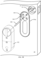
- FIG. 2A-2D are front views of a door lock 200 mounted on a door 20 in different orientations.
- a door lock may be configured to be mounted in any of at least four orientations.
- FIG. 2B depicts a door lock 200 mounted on a door 20 in a second orientation.
- a door handle 24 of the door 20 is arranged directly above a deadbolt of the door 20.
- the door lock 200 is mounted in a vertical orientation such that the door lock 200 extends down and away from the deadbolt, with lock 200 located on the door such that the actuator and thumb turn or handle of the door lock 200 are mounted over a key or driveshaft of the existing lock set (see discussion of FIGs. 1B-1C above).
- the primary axis of the housing is aligned with the height axis of the door and the first end of the housing is located closer to the top of the door than the second end.
- FIG. 2C depicts a door lock 200 mounted on a door 20 in a third orientation.
- a door handle 24 of the door 20 is arranged directly below a deadbolt of the door 20.
- a doorbell 26 or other door-mounted component is arranged directly above the deadbolt.
- the door lock 200 is mounted in a horizontal orientation such that the door lock 200 extends to the left and away from the edge of the door, with lock 200 located on the door such that the actuator and thumb turn or handle of the door lock 200 are mounted over a key or driveshaft of the existing lock set (see discussion of FIGs. 1B-1C above).
- the primary axis of the housing is aligned with a width axis of the door and the first end is located to the right of the second end.
- FIG. 2D depicts a door lock 200 mounted on a door 20 in a fourth orientation.
- a door handle 24 of the door 20 is arranged directly below a deadbolt of the door 20.
- a doorbell 26 or other component is arranged directly above the deadbolt.
- the door of FIG. 2D is of the opposite sense. That is, whereas the door 20 of FIG. 2C includes hinges 22 toward the left side of the door and the handle 24 toward the right side of the door, the door 20 of FIG. 2D includes hinges 22 toward the right side of the door and the handle 24 toward the left side of the door.
- the door lock 200 is mounted in a horizontal orientation such that the door lock 200 extends to the right and away from the edge of the door, with lock 200 located on the door such that the actuator and thumb turn or handle of the door lock 200 are mounted over a key or driveshaft of the existing lock set (see discussion of FIGs. 1B-1C above).
- the primary axis of the housing is aligned with a width axis of the door and the first end is located to the left of the second end.
- the position of a door lock relative to a handle of the door is non-limiting.
- the door lock could be mounted in a horizontal left or horizontal right orientation at a location above or below the handle, or the door lock could be mounted in a vertical up or vertical down orientation at a location above or below the handle, (assuming no other door components are mounted to the door that would be in the way, of course).
- An orientation of the door lock e.g., vertical up, vertical down, horizontal left, horizontal right, or any other
- a door lock may be mounted in any orientation on either side of a door of any sense (i.e., whether the door hinges are to the right or to the left).
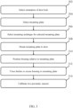
- FIG. 3 is a flow chart for a method of installing a door lock according to some exemplary embodiments described herein.
- a desired orientation of the door lock is selected. As described above, an orientation of a door lock may be selected based at least in part on the locations and orientations of other door components, user preference, or other factors.
- an appropriate mounting plate is selected. The selection of the mounting plate may depend at least in part on the selected orientation of the door lock, in addition to other factors including but not limited to the style and/or design of the deadbolt to be retrofitted or the locations and orientations of other door components, such as a door handle.
- an appropriate mounting technique is selected for the selected mounting plate.
- mounting techniques may include (but are not limited to) screws to engage with preexisting deadbolt hardware, set screws to engage with a lock cylinder, and adhesive to adhere to a surface of the deadbolt or door.
- the mounting plate is mounted to the door, which may include mounting the mounting plate to a deadbolt of the door. In some embodiments, the mounting plate may be secured to the door in one of at least four orientations.
- the housing is positioned relative to the mounting plate.
- the position of the housing relative to the mounting plate may depend at least in part on the desired orientation of the door lock as well as the orientation of the mounting plate.
- positioning a housing relative to the mounting plate may include engaging an actuator and/or a transmission disposed within the housing with a driveshaft and/or other component of a preexisting deadbolt of the door.
- the actuator may be configured to drive a bolt of the deadbolt to a locked position and/or to an unlocked position via the transmission and/or the driveshaft.
- latches of the door lock are closed to secure the housing of the door lock to the mounting plate.
- two (or more) proximity sensors are calibrated.
- Calibration of the proximity sensors may include opening and closing the door, and recording signals produced by the proximity sensors. For example, while the door is closed, a user may indicate to the processor that the door is closed via a user interface, and the processor may record the corresponding signals from the proximity sensors as indicative of the door being closed. A similar procedure may be repeated when the door is open, or at multiple different states of the door being open.
- proximity sensors may be calibrated in any of a plurality of different ways.
- installing a door lock may additionally include manually selecting an orientation of the housing via a user interface.
- a user interface may be integrated with the housing of the door lock in some embodiments, and in such a case may take any suitable form, as embodiments are not limited in this respect.
- a switch or button may be used to input the orientation.
- the user interface may not be integrated with the housing, but may instead be located on another device.
- a user's computing device e.g., a smart phone, a wearable computing device such as a smart watch or smart glasses, a tablet computing device, a laptop or desktop personal computer, a personal digital assistant (PDA), or other device
- a user's computing device may execute software such as an app and may, through the software, present a user interface to the user.
- the user may operate the user interface to input orientation into the user interface.
- the software and the device may then wirelessly communicate the orientation to a processor disposed within the housing, and the processor may store the orientation information upon receipt.
- installing a door lock may additionally include securing a magnet or magnetic material to a door jamb associated with the door.
- the proximity sensors are embodied as other sensors to sense another material or device, installation may include securing such other material or device to the jamb.
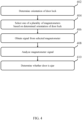
- FIG. 4 is a flow chart for a method of determining whether a door is ajar according to some exemplary embodiments described herein.
- the method of FIG. 4 may be implemented by the door lock via executable instructions stored on one or more storages (e.g., memory) of the door lock and executed by a processor of the door lock, or otherwise implemented by a control circuit.
- storages e.g., memory
- the door lock determines an orientation in which it was mounted to the door.
- the door lock may determine the orientation automatically by analyzing signals of an accelerometer (or other sensor) of the door lock.
- the door lock may determine the orientation in accordance with information received via a user interface from a user who manually enters the information.
- the door lock may obtain the information via any suitable user interface, including a user interface integrated with the door lock or another user interface, and in some embodiments may receive orientation information wirelessly from a computing device separate from the door lock, such as from a smartphone of the user running an associated application.
- the door lock selects one of a plurality of magnetometers of the door lock as a primary magnetometer.
- the primary magnetometer may be selected based at least in part on the determined orientation of the door lock.
- the door lock may be configured with information on the locations of each of the magnetometers in the door lock, and the door lock may select a magnetometer that is in a location closest to a door jamb when the door is closed.
- the door lock may be configured to select a certain magnetometer as the primary magnetometer when the lock is in a certain orientation.
- a signal from the selected magnetometer is obtained.
- the door lock analyzes the magnetometer signal as part of determining a door status (e.g., closed or ajar).
- the door lock compares the signal to a reference signal, such as a signal generated during a calibration routine.
- a reference signal may correspond to an expected value of the magnetometer signal when the door is closed. If the signal from the magnetometer at a time matches the reference signal, such as equaling the reference signal and/or being within a threshold amount of the reference signal, the door may be closed. If, however, the magnetometer signal does not match the reference signal, the door may be open.
- the door lock may analyze the magnetometer signal with respect to the reference signal to make this determination.
- FIG. 4 The method of FIG. 4 was described in connection with use of one signal from one magnetometer. It should be appreciated, however, that embodiments are not so limited.
- one magnetometer may be treated as the primary magnetometer and may be chiefly used to determine door status
- one or more secondary magnetometers may additionally be used to determine door status.
- a result of analyzing a primary magnetometer's signal may be weighted most in making a determination of door status, while the result(s) of analyzing the signal(s) from the secondary magnetometer(s) may be weighted less.
- the signals may in some embodiments be analyzed in similar ways.
- each of the magnetometer signals may be respectively compared to a corresponding reference signal, each of which may have been obtained during a calibration. If all signals match the reference signals and thus all indicate that the door is closed, then the determination may be made that the door is closed. If the comparison result for the primary magnetometer indicates that the door is closed but the comparison result for the secondary magnetometer indicates that the door is open, the comparison result from the primary magnetometer may be used as the result. Or, if the two results differ, the door lock may determine that the door status is uncertain, or may output a status determination that indicates that the door may be in one status but that another of the magnetometers indicates that the door may be in another status.
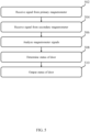
- FIG. 5 is a flow chart for another method of determining a status of a door according to some exemplary embodiments described herein.
- the method of FIG. 5 may, in some embodiments, be used to determine whether a door is being subjected to an attack, such as in a scenario in which an attacker is using a foreign magnet to try to cause a magnetometer of the door lock to output an incorrect value and cause the door lock to reach an incorrect conclusion about the door status.
- the method of FIG. 4 may be implemented by the door lock via executable instructions stored on one or more storages (e.g., memory) of the door lock and executed by a processor of the door lock, or otherwise implemented by a control circuit.
- a status of a door may be determined for any appropriate reason, including but not limited to simply confirming the status of the door, or determining whether or not to unlock the door, such as in response to a request to unlock the door.
- the door lock receives a first signal from a primary magnetometer of the door lock.
- the door lock may select a primary magnetometer based at least in part on an orientation of the door lock, including using techniques described above.
- the door lock receives a second signal from a secondary magnetometer of the door lock.
- the door lock analyzes the first and second signals. Analyzing the signals may include comparing the first signal to a first reference signal and the second signal to a second reference signal. As described above, reference signals may be generated during a calibration routine.
- the door lock may also determine whether the first and second signals are consistent with one another. For example, if the first signal matches a corresponding reference value and the second signal does not (or vice versa), the door lock may determine that the two signals are inconsistent with one another. As another example, in some embodiments, the door lock may determine whether, for a given value of the first reference signal, the value of the second signal matches an expected value of the second signal. This may be done because, under ordinary circumstances (i.e., not during an attack), the two magnetometers may output signals in a predictable manner, and in a manner that varies predictably.
- the magnetometers may output a signal that varies along the swing path of the door, as the magnetometers move farther away from or closer to a magnet disposed on a jamb, and may output that same signal (or a signal within a threshold difference of tolerance) each time the door is swung.
- the door lock may determine, for a given value obtained in block 502 for a magnetometer, whether the value of the signal for the other magnetometer matches the expected/predicted value for that magnetometer.
- the door lock may determine whether recent changes in the values of the first and second signals output by the magnetometers have been consistent. For example, a first signal changing significantly while a second signal remains constant may be inconsistent with signals output by magnetometers that are both mounted on the same door and thus should change or hold constant together, and may be indicative of an attack.
- An unexpected state may in some cases be indicative of an attack (e.g., an in-progress break-in attempt), or in other cases may be indicative of an error.
- detecting an unexpected state may include determining that the first and second signals do not both indicate the same door status, or are inconsistent with one another.
- unexpected states may be detected based on the first and second signals in other ways.
- the door lock outputs the status of the door.
- Outputting the status of the door may include, in a case that an unexpected state is determined (which may be indicative of an attack) wirelessly sending an alert from the door lock to a recipient outside the door lock, such as to an owner of the door lock or to law enforcement.
- an unexpected state is determined (which may be indicative of an attack) wirelessly sending an alert from the door lock to a recipient outside the door lock, such as to an owner of the door lock or to law enforcement.
- an unexpected state is determined (which may be indicative of an attack) wirelessly sending an alert from the door lock to a recipient outside the door lock, such as to an owner of the door lock or to law enforcement.
- the owner of the lock and/or law enforcement may be notified.
- a door lock error may be detected, and only the owner of the lock may be notified and not law enforcement.
- the method may also include configuring the door lock to refrain from unlocking the door lock in response to a detection of a possible attack on the door.
- some successful attacks on the door may cause a door lock to unlock automatically.
- the door lock may not unlock for a time, even in response to a request to unlock that purports to be received from the homeowner or another valid user of the lock. This may prevent opening of the door in a scenario in which the door lock has detected that an attempt to break into the door is underway.
- the door lock may only refrain from unlocking for a certain time period, which may be configured. For example, a suitable time period may be five minutes, ten minutes, one hour, or other suitable time period.
- processors may be implemented as integrated circuits, with one or more processors in an integrated circuit component, including commercially available integrated circuit components known in the art by names such as CPU chips, GPU chips, microprocessor, microcontroller, or co-processor.
- processors may be implemented in custom circuitry, such as an ASIC, or semicustom circuitry resulting from configuring a programmable logic device.
- a processor may be a portion of a larger circuit or semiconductor device, whether commercially available, semi-custom or custom.
- some commercially available microprocessors have multiple cores such that one or a subset of those cores may constitute a processor.
- a processor may be implemented using circuitry in any suitable format.
- Such processors may be interconnected by one or more networks in any suitable form, including as a local area network or a wide area network, such as an enterprise network or the Internet.
- networks may be based on any suitable technology and may operate according to any suitable protocol and may include wireless networks, wired networks or fiber optic networks.
- the various methods or processes outlined herein may be coded as software that is executable on one or more processors that employ any one of a variety of operating systems or platforms. Additionally, such software may be written using any of a number of suitable programming languages and/or programming or scripting tools, and also may be compiled as executable machine language code or intermediate code that is executed on a framework or virtual machine.
- the embodiments described herein may be embodied as a computer readable storage medium (or multiple computer readable media) (e.g., a computer memory, one or more floppy discs, compact discs (CD), optical discs, digital video disks (DVD), magnetic tapes, flash memories, circuit configurations in Field Programmable Gate Arrays or other semiconductor devices, or other tangible computer storage medium) encoded with one or more programs that, when executed on one or more computers or other processors, perform methods that implement the various embodiments discussed above.
- a computer readable storage medium may retain information for a sufficient time to provide computer-executable instructions in a non-transitory form.
- Such a computer readable storage medium or media can be transportable, such that the program or programs stored thereon can be loaded onto one or more different computers or other processors to implement various aspects of the present invention as discussed above.
- the term "computer-readable storage medium” encompasses only a non-transitory computer-readable medium that can be considered to be a manufacture (i.e., article of manufacture) or a machine.
- the invention may be embodied as a computer readable medium other than a computer-readable storage medium, such as a propagating signal.
- program or “software” are used herein in a generic sense to refer to any type of computer code or set of computer-executable instructions that can be employed to program a computer or other processor to implement various aspects of the present disclosure as discussed above. Additionally, it should be appreciated that according to one aspect of this embodiment, one or more computer programs that when executed perform methods of the present invention need not reside on a single computer or processor, but may be distributed in a modular fashion amongst a number of different computers or processors to implement various aspects of the present invention.
- Computer-executable instructions may be in many forms, such as program modules, executed by one or more computers or other devices.
- program modules include routines, programs, objects, components, data structures, etc. that perform particular tasks or implement particular abstract data types.
- functionality of the program modules may be combined or distributed as desired in various embodiments.
- data structures may be stored in computer-readable media in any suitable form.
- data structures may be shown to have fields that are related through location in the data structure. Such relationships may likewise be achieved by assigning storage for the fields with locations in a computer-readable medium that conveys relationship between the fields.
- any suitable mechanism may be used to establish a relationship between information in fields of a data structure, including through the use of pointers, tags or other mechanisms that establish relationship between data elements.
- embodiments described herein may be embodied as a method, of which an example has been provided.
- the acts performed as part of the method may be ordered in any suitable way. Accordingly, embodiments may be constructed in which acts are performed in an order different than illustrated, which may include performing some acts simultaneously, even though shown as sequential acts in illustrative embodiments.
- actions are described as taken by a "user.” It should be appreciated that a "user” need not be a single individual, and that in some embodiments, actions attributable to a "user” may be performed by a team of individuals and/or an individual in combination with computer-assisted tools or other mechanisms.
Landscapes
- Engineering & Computer Science (AREA)
- Physics & Mathematics (AREA)
- Computer Networks & Wireless Communication (AREA)
- General Physics & Mathematics (AREA)
- Mechanical Engineering (AREA)
- Electromagnetism (AREA)
- Structural Engineering (AREA)
- Lock And Its Accessories (AREA)
- Physical Deposition Of Substances That Are Components Of Semiconductor Devices (AREA)
Claims (15)
- Verfahren zum Feststellen, ob eine Tür (10) einen Spaltbreit offen steht, wobei das Verfahren umfasst:Feststellen einer Ausrichtung eines Türschlosses (100) der Tür;beruhend auf der Ausrichtung des Türschlosses, Analysieren von mindestens einem Signal von mindestens einem oder zwei oder mehreren Näherungssensoren (120, 122) des Türschlosses; undFeststellen, ob die Tür einen Spaltbreit offen steht, und zwar zumindest teilweise beruhend auf einem Ergebnis der Analyse des mindestens einen Signals.
- Verfahren nach Anspruch 1, wobei das Feststellen der Ausrichtung des Türschlosses umfasst, die Ausrichtung des Türschlosses unter Verwendung eines Beschleunigungsmessers (130) des Türschlosses festzustellen.
- Verfahren nach Anspruch 1 oder Anspruch 2, wobei das Feststellen der Ausrichtung des Türschlosses ein Feststellen auf der Grundlage von Informationen umfasst, die über eine Benutzerschnittstelle empfangen werden und mit der Ausrichtung des Türschlosses zusammenhängen.
- Verfahren nach Anspruch 3, darüber hinaus umfassend:
drahtloses Empfangen, von einer vom Türschloss separaten Datenverarbeitungsvorrichtung, der Informationen, die über die Benutzerschnittstelle empfangen werden und mit der Ausrichtung zusammenhängen. - Verfahren nach einem der Ansprüche 1-4, wobei das Analysieren des mindestens einen Signals zumindest teilweise beruhend auf der Ausrichtung des Türschlosses umfasst, zwei oder mehr Signale zu analysieren, die von den zwei oder mehr Näherungssensoren empfangen werden, und zwar zumindest teilweise beruhend auf der Ausrichtung des Türschlosses und einer relativen Stärke der zwei oder mehr Signale.
- Verfahren nach einem der Ansprüche 1-5, wobei das Analysieren des mindestens einen Signals von dem mindestens einen der zwei oder mehr Näherungssensoren des Türschlosses umfasst, mindestens ein Signal von mindestens einem von zwei oder mehr Magnetsensoren des Türschlosses zu analysieren.
- Verfahren nach einem der Ansprüche 1-6, wobei:die zwei oder mehr Näherungssensoren des Türschlosses einen ersten Näherungssensor und einen zweiten Näherungssensor aufweisen; unddas Analysieren des mindestens einen Signals beruhend auf der Ausrichtung des Türschlosses umfasst, ein erstes Signal aus mindestens zwei Signalen auszuwählen, die von den zwei oder mehr Näherungssensoren des Türschlosses ausgegeben werden.
- Vorrichtung, aufweisend:ein Stellglied, um einen Riegel eines Türschlosses einer Tür in eine verriegelte Position und/oder eine entriegelte Position zu fahren;ein Gehäuse (102), das dafür ausgelegt ist, an der Tür montiert zu werden, wobei das Stellglied zumindest teilweise innerhalb des Gehäuses angeordnet ist, wobei das Gehäuse eine Hauptachse und eine Sekundärachse senkrecht zur Hauptachse aufweist, das Gehäuse in einer ersten Abmessung entlang der Hauptachse länger ist als in einer zweiten Abmessung entlang der Sekundärachse, das Gehäuse ein erstes Ende und ein zweites Ende entgegengesetzt zum ersten Ende entlang der Hauptachse aufweist, und das Stellglied im Gehäuse dafür ausgelegt ist, den Riegel über eine Schnittstelle anzutreiben, die proximal zum ersten Ende des Gehäuses angeordnet ist;einen ersten Sensor, der proximal zum ersten Ende des Gehäuses angeordnet ist;einen zweiten Sensor, der proximal zum zweiten Ende des Gehäuses angeordnet ist;mindestens einen Prozessor, der innerhalb des Gehäuses angeordnet ist; und mindestens ein Speichermedium, das innerhalb des Gehäuses angeordnet ist und auf dem ausführbare Anweisungen codiert sind, die bei Ausführung den mindestens einen Prozessor dazu veranlassen, ein Verfahren auszuführen, welches umfasst:Feststellen einer Ausrichtung der Vorrichtung an der Tür; undFeststellen, ob die Tür einen Spaltbreit offen steht, und zwar zumindest teilweise beruhend auf der Ausrichtung der Vorrichtung an der Tür und einem oder mehreren Signalen, die von einem oder beiden des ersten und zweiten Sensors empfangen werden.
- Vorrichtung nach Anspruch 8,wobei die Vorrichtung dafür ausgelegt ist, an der Tür in einer beliebigen von mindestens vier Ausrichtungen montiert zu werden,wobei die Vorrichtung so ausgelegt ist, dass, wenn sie an der Tür in einer ersten Ausrichtung der mindestens vier Ausrichtungen montiert ist, die Hauptachse des Gehäuses mit einer Höhenachse der Tür ausgerichtet ist und das erste Ende des Gehäuses sich näher an einer Oberseite der Tür befindet als das zweite Ende;wobei die Vorrichtung so ausgelegt ist, dass, wenn sie an der Tür in einer zweiten Ausrichtung der mindestens vier Ausrichtungen montiert ist, die Hauptachse des Gehäuses mit der Höhenachse der Tür ausgerichtet ist und das zweite Ende des Gehäuses sich näher an der Oberseite der Tür befindet als das erste Ende;wobei die Vorrichtung so ausgelegt ist, dass, wenn sie an der Tür in einer dritten Ausrichtung der mindestens vier Ausrichtungen montiert ist, die Hauptachse des Gehäuses mit einer Breitenachse der Tür ausgerichtet ist und das erste Ende sich rechts vom zweiten Ende befindet; undwobei die Vorrichtung so ausgelegt ist, dass, wenn sie an der Tür in einer vierten Ausrichtung der mindestens vier Ausrichtungen montiert ist, die Hauptachse des Gehäuses mit der Breitenrichtung der Tür ausgerichtet ist und das erste Ende sich links vom zweiten Ende befindet.
- Vorrichtung nach Anspruch 8 oder 9, wobei es sich bei dem ersten und zweiten Sensor jeweils um einen Näherungssensor handelt.
- Vorrichtung nach Anspruch 10, wobei es sich bei dem ersten und zweiten Sensor jeweils um einen Magnetsensor handelt.
- Vorrichtung nach einem der Ansprüche 8-11, darüber hinaus aufweisend:ein Bauteil, das an einem der Tür zugehörigen Türrahmen zu befestigen ist,wobei der erste und der zweite Sensor jeweils dafür ausgelegt sind, das am Türrahmen montierte Bauteil zu erfassen.
- Vorrichtung nach Anspruch 11, darüber hinaus aufweisend:einen Magneten (150), der an einem der Tür zugehörigen Türrahmen zu befestigen ist,wobei der erste und der zweite Sensor jeweils dafür ausgelegt sind, den am Türrahmen montierten Magneten zu erfassen.
- Bausatz, aufweisend:die Vorrichtung nach einem der vorhergehenden Vorrichtungsansprüche; undeine Mehrzahl von Montageplatten (104a, 104b) zur Montage der Vorrichtung an der Tür in verschiedenen Ausrichtungen, wobei jede aus der Mehrzahl von Montageplatten dafür ausgelegt ist, das Gehäuse der Vorrichtung in einer Mehrzahl von Ausrichtungen aufzunehmen.
- Bausatz nach Anspruch 14, darüber hinaus aufweisend:einen Magneten, der dafür ausgelegt ist, an einem der Tür zugehörigen Türrahmen montiert zu werden,wobei der erste und der zweite Sensor jeweils dafür ausgelegt sind, den Magnete zu erfassen.
Applications Claiming Priority (2)
| Application Number | Priority Date | Filing Date | Title |
|---|---|---|---|
| US202063083727P | 2020-09-25 | 2020-09-25 | |
| PCT/US2021/050235 WO2022066469A1 (en) | 2020-09-25 | 2021-09-14 | Multi-orientation door lock |
Publications (4)
| Publication Number | Publication Date |
|---|---|
| EP4217558A1 EP4217558A1 (de) | 2023-08-02 |
| EP4217558A4 EP4217558A4 (de) | 2024-11-13 |
| EP4217558B1 true EP4217558B1 (de) | 2025-04-30 |
| EP4217558C0 EP4217558C0 (de) | 2025-04-30 |
Family
ID=80822728
Family Applications (1)
| Application Number | Title | Priority Date | Filing Date |
|---|---|---|---|
| EP21873208.9A Active EP4217558B1 (de) | 2020-09-25 | 2021-09-14 | Mehrfachrichtungstürschloss |
Country Status (8)
| Country | Link |
|---|---|
| US (1) | US12180750B2 (de) |
| EP (1) | EP4217558B1 (de) |
| JP (1) | JP2023543572A (de) |
| KR (1) | KR20230091860A (de) |
| CN (1) | CN116348651A (de) |
| AU (1) | AU2021346527A1 (de) |
| IL (1) | IL301486A (de) |
| WO (1) | WO2022066469A1 (de) |
Families Citing this family (20)
| Publication number | Priority date | Publication date | Assignee | Title |
|---|---|---|---|---|
| US9704314B2 (en) | 2014-08-13 | 2017-07-11 | August Home, Inc. | BLE/WiFi bridge that detects signal strength of Bluetooth LE devices at an exterior of a dwelling |
| US11802422B2 (en) | 2013-03-15 | 2023-10-31 | August Home, Inc. | Video recording triggered by a smart lock device |
| US11639617B1 (en) | 2019-04-03 | 2023-05-02 | The Chamberlain Group Llc | Access control system and method |
| GB2584101B (en) * | 2019-05-20 | 2023-05-17 | Avantis Hardware Ltd | An attachment system |
| US11959308B2 (en) * | 2020-09-17 | 2024-04-16 | ASSA ABLOY Residential Group, Inc. | Magnetic sensor for lock position |
| WO2022066469A1 (en) | 2020-09-25 | 2022-03-31 | ASSA ABLOY Residential Group, Inc. | Multi-orientation door lock |
| WO2022066470A1 (en) * | 2020-09-25 | 2022-03-31 | ASSA ABLOY Residential Group, Inc. | Door lock with magnetometers |
| US20240301722A1 (en) * | 2021-03-22 | 2024-09-12 | Graeme McGrath | Improved door lock system |
| US20230008687A1 (en) * | 2021-07-07 | 2023-01-12 | Palatiumcare, Inc. | Systems and methods for securing doors with magnetic locks |
| USD993000S1 (en) | 2021-12-20 | 2023-07-25 | ASSA ABLOY Residential Group, Inc. | Lock |
| USD992999S1 (en) | 2021-12-20 | 2023-07-25 | ASSA ABLOY Residential Group, Inc. | Lock |
| US12291903B2 (en) | 2021-12-20 | 2025-05-06 | ASSA ABLOY Residential Group, Inc. | Deadbolt lock system |
| US12281495B2 (en) * | 2022-08-01 | 2025-04-22 | Master Lock Company Llc | Gearbox clutch mechanism for motorized lock |
| ES2970591A1 (es) * | 2022-10-26 | 2024-05-29 | Salto Systems Sl | Soporte para instalar dispositivos de apertura y cierre en cilindros de cerraduras |
| TWI832672B (zh) * | 2023-01-13 | 2024-02-11 | 東隆五金工業股份有限公司 | 電子鎖與電子鎖的開門設定方法 |
| CN118622078A (zh) * | 2023-03-10 | 2024-09-10 | 安克创新科技股份有限公司 | 锁具以及锁具开关锁的控制方法 |
| USD1061215S1 (en) | 2023-04-20 | 2025-02-11 | Master Lock Company Llc | Door lock |
| USD1091287S1 (en) * | 2023-08-09 | 2025-09-02 | Lumi United Technology Co., Ltd. | Smart door lock |
| USD1113392S1 (en) * | 2024-10-18 | 2026-02-17 | Meta Intelligence LLC | Door lock |
| USD1082487S1 (en) * | 2024-11-27 | 2025-07-08 | Meta Intelligence LLC | Door lock |
Family Cites Families (270)
| Publication number | Priority date | Publication date | Assignee | Title |
|---|---|---|---|---|
| US2680177A (en) | 1951-11-15 | 1954-06-01 | Myron A Coler | Logarithmic potentiometer |
| US3249915A (en) | 1965-04-20 | 1966-05-03 | Trw Inc | Method and apparatus for vehicle detection |
| US3898976A (en) | 1974-10-21 | 1975-08-12 | Lewbill Ind Inc | Humidifier mounting for warm air heating system |
| US4849749A (en) | 1986-02-28 | 1989-07-18 | Honda Lock Manufacturing Co., Ltd. | Electronic lock and key switch having key identifying function |
| US4777563A (en) | 1986-05-02 | 1988-10-11 | Toshiba Battery Co., Ltd. | Thin type electronic instrument |
| CA1307017C (en) | 1987-10-19 | 1992-09-01 | Robert M. Richards | Blocking device for latch mechanism |
| USD316365S (en) | 1989-01-13 | 1991-04-23 | A. L. Hansen Manufacturing Company | Rotary lock |
| US5245329A (en) | 1989-02-27 | 1993-09-14 | Security People Inc. | Access control system with mechanical keys which store data |
| US5306407A (en) | 1989-06-27 | 1994-04-26 | Hauzer Holding Bv | Method and apparatus for coating substrates |
| WO1991019986A1 (en) | 1990-06-11 | 1991-12-26 | Sundstrand Data Control, Inc. | Accelerometer with flexure isolation |
| GB2259737B (en) | 1991-09-19 | 1996-02-07 | Klidi Technology Corp | Remotely-operated self-contained electronic lock security system assembly |
| US5933086A (en) | 1991-09-19 | 1999-08-03 | Schlage Lock Company | Remotely-operated self-contained electronic lock security system assembly |
| US5387903A (en) | 1992-04-24 | 1995-02-07 | Ciposa Microtechniques Sa | Programmable electronic time lock |
| DE4321713C2 (de) | 1992-07-07 | 1994-08-25 | Ford Werke Ag | Zusammengesetzter Scheibenbremsenrotor und Verfahren zu seiner Herstellung |
| USD361985S (en) | 1993-05-06 | 1995-09-05 | Chrysler Corporation | Front panel for a car heater and air conditioner control unit |
| US5774058A (en) | 1995-07-20 | 1998-06-30 | Vindicator Corporation | Remote access system for a programmable electronic lock |
| US5841361A (en) | 1996-03-18 | 1998-11-24 | Hoffman; Ronald J. | Keyless locking system |
| GB2312513B (en) | 1996-04-26 | 2000-01-12 | Tseng Hsin Te | Double grid mechanical encoder |
| US5979199A (en) | 1996-09-13 | 1999-11-09 | Access Technologies, Inc. | Electrically operated actuator |
| JP3317176B2 (ja) | 1997-02-06 | 2002-08-26 | 松下電器産業株式会社 | 映像伝送装置 |
| EP0906620B1 (de) | 1997-04-08 | 2004-03-03 | Koninklijke Philips Electronics N.V. | Einrichtung und verfahren zum aufzeichnen eines informationssignales in einem aufzeichnungsträger |
| US6032500A (en) | 1997-04-18 | 2000-03-07 | Stephen C. Cohen | Kit for retrofitting a door with a security lock system |
| US5903225A (en) | 1997-05-16 | 1999-05-11 | Harris Corporation | Access control system including fingerprint sensor enrollment and associated methods |
| GB9720911D0 (en) | 1997-10-03 | 1997-12-03 | Britax Rainsfords Pty Ltd | Hall effect sensor system |
| KR100283073B1 (ko) | 1997-10-13 | 2001-03-02 | 정선종 | 이동통신시스템에서매체액세스제어프레임구조를이용한제어평면정보송수신방법 |
| US7614008B2 (en) | 2004-07-30 | 2009-11-03 | Apple Inc. | Operation of a computer with touch screen interface |
| US7663607B2 (en) | 2004-05-06 | 2010-02-16 | Apple Inc. | Multipoint touchscreen |
| US8479122B2 (en) | 2004-07-30 | 2013-07-02 | Apple Inc. | Gestures for touch sensitive input devices |
| IL137478A (en) | 1998-01-26 | 2005-11-20 | Westerman Wayne | Method and apparatus for integrating manual input |
| US7844914B2 (en) | 2004-07-30 | 2010-11-30 | Apple Inc. | Activating virtual keys of a touch-screen virtual keyboard |
| DE19807553C1 (de) | 1998-02-23 | 1999-07-01 | Keso Gmbh | Antriebsvorrichtung für ein Schloß, einen Schließzylinder oder dgl. |
| CA2276300A1 (en) | 1998-06-24 | 1999-12-24 | Rytec Corporation | Seal for a bi-parting door |
| CN1312928A (zh) | 1998-08-14 | 2001-09-12 | 3M创新有限公司 | 射频识别系统的应用 |
| DE19844360A1 (de) | 1998-09-28 | 2000-04-13 | Anatoli Stobbe | Zugangskontrollsystem |
| USD437771S1 (en) | 1999-08-13 | 2001-02-20 | Emhart Inc. | Mounting plate |
| US6961763B1 (en) | 1999-08-17 | 2005-11-01 | Microsoft Corporation | Automation system for controlling and monitoring devices and sensors |
| DE19951463A1 (de) | 1999-10-26 | 2001-05-03 | Kiekert Ag | Kraftfahrzeugtürverschluß |
| US6422457B1 (en) | 2000-02-21 | 2002-07-23 | Mark R. Frich | Access device for a materials depository |
| JP2002048174A (ja) | 2000-08-01 | 2002-02-15 | Nisshinbo Ind Inc | 摩擦部材及びその製造方法 |
| US6334636B1 (en) | 2000-08-09 | 2002-01-01 | Taiwan Fu Hsing Industrial Co., Ltd. | Remotely controllable lock |
| US6360573B1 (en) | 2000-09-11 | 2002-03-26 | Summit Automation Co., Ltd | Mechanism for locking and unlocking electronic safe lock barrel |
| US6568726B1 (en) | 2000-10-30 | 2003-05-27 | Shlomo Caspi | Universal electromechanical strike locking system |
| US6677932B1 (en) | 2001-01-28 | 2004-01-13 | Finger Works, Inc. | System and method for recognizing touch typing under limited tactile feedback conditions |
| US6570557B1 (en) | 2001-02-10 | 2003-05-27 | Finger Works, Inc. | Multi-touch system and method for emulating modifier keys via fingertip chords |
| US6729169B2 (en) | 2001-03-27 | 2004-05-04 | Randall L. Moore | Dual cylinder deadbolt adjunct |
| USD456689S1 (en) | 2001-05-31 | 2002-05-07 | Alpha Corporation | Portion of lock |
| US7248836B2 (en) | 2001-09-30 | 2007-07-24 | Schlage Lock Company | RF channel linking method and system |
| US6472993B1 (en) | 2001-10-16 | 2002-10-29 | Pittway Corp. | Singular housing window or door intrusion detector using earth magnetic field sensor |
| US6967562B2 (en) | 2002-02-22 | 2005-11-22 | Royal Thoughts, Llc | Electronic lock control and sensor module for a wireless system |
| US20030167693A1 (en) | 2002-03-11 | 2003-09-11 | Radio Systems Corporation | Automatic door opening and closing apparatus with lock |
| US6972660B1 (en) | 2002-05-15 | 2005-12-06 | Lifecardid, Inc. | System and method for using biometric data for providing identification, security, access and access records |
| US6737877B1 (en) | 2002-08-30 | 2004-05-18 | Cypress Semiconductor Corp. | Method and circuit for reading a potentiometer |
| US7221272B2 (en) | 2003-05-30 | 2007-05-22 | Hubert Hosselet | Electronic lock module |
| US6891479B1 (en) | 2003-06-12 | 2005-05-10 | Jon E. Eccleston | Remotely controllable automatic door operator and closer |
| US7015943B2 (en) | 2003-07-11 | 2006-03-21 | Chiang Thomas S C | Premises entry security system |
| USD507171S1 (en) | 2003-07-22 | 2005-07-12 | Southco, Inc. | Camming latch |
| SE527340C2 (sv) | 2003-09-04 | 2006-02-14 | Aptus Elektronik Ab | Anordning vid lås |
| US7252311B2 (en) | 2003-09-17 | 2007-08-07 | Hartwell Corporation | Motor driven latch |
| FR2861784B1 (fr) | 2003-11-05 | 2006-01-21 | Somfy | Procede de configuration d'une serrure electrique motorisee et serrure electrique pour la mise en oeuvre de ce procede |
| US7127083B2 (en) | 2003-11-17 | 2006-10-24 | Vidient Systems, Inc. | Video surveillance system with object detection and probability scoring based on object class |
| US20050179517A1 (en) | 2004-02-17 | 2005-08-18 | Harms Mark R. | Retrofit electronic lock security system |
| CN100570115C (zh) | 2004-03-16 | 2009-12-16 | 株式会社易保 | 易于改进的电子控制门锁系统 |
| US7420456B2 (en) | 2004-03-19 | 2008-09-02 | Sentri Lock, Inc. | Electronic lock box with multiple modes and security states |
| US7653883B2 (en) | 2004-07-30 | 2010-01-26 | Apple Inc. | Proximity detector in handheld device |
| WO2006041873A2 (en) | 2004-10-05 | 2006-04-20 | Harrow Products Llc | Lock input device for a security system |
| US7373795B2 (en) | 2004-12-07 | 2008-05-20 | Kilbourne Mark W | Universal remote deadbolt adapter |
| WO2006085852A2 (en) | 2005-01-28 | 2006-08-17 | Hermetic Switch, Inc. | A deadbolt sensor for security systems |
| US7643056B2 (en) | 2005-03-14 | 2010-01-05 | Aptina Imaging Corporation | Motion detecting camera system |
| WO2006116643A2 (en) | 2005-04-27 | 2006-11-02 | Superb Industries, Inc. | Keyless entry system |
| US8024186B1 (en) | 2005-05-24 | 2011-09-20 | Mobitv, Inc. | System and method for location based interaction with a device |
| DE102005039532B4 (de) | 2005-08-18 | 2012-05-31 | Novoferm Tormatic Gmbh | Antriebseinheit für eine Tür oder ein Tor, insbesondere für ein Garagentor und Verfahren zum Betrieb einer solchen Antriebseinheit für eine Tür oder ein Tor, insbesondere für ein Garagentor |
| US7520152B2 (en) | 2005-09-13 | 2009-04-21 | Eaton Corporation | Lock device and system employing a door lock device |
| US7633076B2 (en) | 2005-09-30 | 2009-12-15 | Apple Inc. | Automated response to and sensing of user activity in portable devices |
| US8864049B2 (en) | 2005-10-21 | 2014-10-21 | Durr Systems Gmbh | Rotary atomizer with a spraying body |
| US7657849B2 (en) | 2005-12-23 | 2010-02-02 | Apple Inc. | Unlocking a device by performing gestures on an unlock image |
| US7734249B1 (en) | 2006-03-01 | 2010-06-08 | Sprint Spectrum L.P. | Method and system for reporting usage of a repeater in wireless communications |
| US8019353B1 (en) | 2006-03-01 | 2011-09-13 | Sprint Spectrum L.P. | Method and system for reporting fiber optic delay for use in locating a wireless communication device |
| ATE407278T1 (de) | 2006-03-16 | 2008-09-15 | Fiat Ricerche | Manuelle betätigungsvorrichtung mit formgedächtnishilfsantrieb |
| US8279180B2 (en) | 2006-05-02 | 2012-10-02 | Apple Inc. | Multipoint touch surface controller |
| US7891222B2 (en) | 2006-06-12 | 2011-02-22 | Hafele America Company | Electronic locking system |
| USD559077S1 (en) | 2006-06-29 | 2008-01-08 | The Boeing Company | Decompression rotary latch |
| US7696858B2 (en) | 2006-07-17 | 2010-04-13 | Groff John K | Remotely operable door lock interface system |
| US7351910B1 (en) | 2006-09-21 | 2008-04-01 | Hubbell Incorporated | Electrical box assembly |
| EP2100454B1 (de) | 2006-11-20 | 2019-10-30 | Axis AB | Drahtlose netzwerkkamerasysteme |
| US8006002B2 (en) | 2006-12-12 | 2011-08-23 | Apple Inc. | Methods and systems for automatic configuration of peripherals |
| US7957762B2 (en) | 2007-01-07 | 2011-06-07 | Apple Inc. | Using ambient light sensor to augment proximity sensor output |
| DE102007014751A1 (de) | 2007-01-24 | 2008-08-07 | Otto Bock Healthcare Products Gmbh | Potentiometer |
| US8615630B2 (en) | 2007-06-28 | 2013-12-24 | Apple Inc. | Systems and methods for managing data storage |
| US8586902B2 (en) | 2007-06-29 | 2013-11-19 | Orion Energy Systems, Inc. | Outdoor lighting fixture and camera systems |
| US8037511B1 (en) | 2007-07-20 | 2011-10-11 | Sprint Communications Company L.P. | Utilizing a mobile device to operate an electronic locking mechanism |
| US8351789B2 (en) | 2007-07-23 | 2013-01-08 | Nistica, Inc. | High resolution digital optical encoder/decoder |
| GB0720972D0 (en) | 2007-10-25 | 2007-12-05 | Renishaw Plc | Magnetic encoder |
| USD576019S1 (en) | 2007-10-29 | 2008-09-02 | Newfrey Llc | Deadbolt interior |
| US8269627B2 (en) | 2007-11-30 | 2012-09-18 | Andersen Corporation | Status monitoring system for a fenestration unit |
| US8040218B2 (en) | 2007-12-31 | 2011-10-18 | Utc Fire & Security Americas Corporation, Inc. | GPS enabled key management system |
| US8445779B1 (en) | 2008-01-09 | 2013-05-21 | Arlington Industries, Inc. | Two gang electrical box for rapid mounting using hole saw |
| US20090193859A1 (en) | 2008-02-04 | 2009-08-06 | Sunnect, Inc. | Automatic locking system and deadbolt having the same |
| TR200801927A2 (tr) | 2008-03-24 | 2009-01-21 | Vemus Endüstri̇yel Elektroni̇k Sanayi̇ Ve Ti̇caret Li̇mi̇ted Şi̇rketi̇ | Mikro motorlu kilitleme dili sistemi. |
| SE532453C2 (sv) | 2008-05-19 | 2010-01-26 | Phoniro Ab | Nyckelbox |
| WO2010071458A1 (en) | 2008-12-17 | 2010-06-24 | Fisher & Paykel Appliances Limited | A laundry machine |
| FI121681B (fi) | 2009-01-05 | 2011-02-28 | Megalock Oy | Lukon lisälaite |
| US8930438B2 (en) | 2009-06-17 | 2015-01-06 | Apple Inc. | Push-based location update |
| CN102472636B (zh) | 2009-07-15 | 2015-06-24 | Skf私人有限公司 | 霍尔效应感应装置 |
| US8653982B2 (en) | 2009-07-21 | 2014-02-18 | Openings | Door monitoring system |
| FR2949268B1 (fr) | 2009-08-20 | 2012-09-28 | Radio Systemes Ingenierie Video Technologies | Dispositif de detection d'entree et de reconnaissance de badges transpondeurs, systeme de surveillance le comprenant et procede de surveillance mis en oeuvre par ledit systeme |
| US8191400B2 (en) | 2009-09-29 | 2012-06-05 | Panasonic Automotive Systems Company Of America | Method and apparatus for supporting accelerometer based controls in a mobile environment |
| US9176542B2 (en) | 2009-11-06 | 2015-11-03 | Sony Corporation | Accelerometer-based touchscreen user interface |
| KR101283683B1 (ko) | 2009-12-14 | 2013-07-08 | 한국전자통신연구원 | 수직축 방향 가속도계 |
| US8310365B2 (en) | 2010-01-08 | 2012-11-13 | Utc Fire & Security Americas Corporation, Inc. | Control system, security system, and method of monitoring a location |
| US8325039B2 (en) | 2010-02-25 | 2012-12-04 | Sargent Manufacturing Company | Locking device with embedded circuit board |
| TR201001561A2 (tr) * | 2010-03-02 | 2011-02-21 | Vemus Endüstri̇yel Elektroni̇k Sanayi̇ Ve Ti̇caret Li̇mi̇ted Şi̇rketi̇ | Dört yönlü elektronik kilit. |
| EP2365475B1 (de) | 2010-03-12 | 2013-05-08 | DESI Alarm ve Güvenlik Sistemleri Sanayi ve Ticaret Ltd. Sti. | Elektrisches Zylinderschloss |
| US8476577B2 (en) | 2010-03-29 | 2013-07-02 | Mitutoyo Corporation | Optical encoder |
| ES2732551T3 (es) | 2010-04-26 | 2019-11-25 | Nidec Avtron Automation Corp | Codificador absoluto |
| JP5379748B2 (ja) | 2010-06-03 | 2013-12-25 | Ntn株式会社 | 磁気エンコーダ |
| US8347720B2 (en) | 2010-06-29 | 2013-01-08 | Tialinx, Inc. | MEMS tunneling accelerometer |
| US8284748B2 (en) | 2010-07-07 | 2012-10-09 | Apple Inc. | Ad hoc formation and tracking of location-sharing groups |
| EP2428774B1 (de) | 2010-09-14 | 2013-05-29 | Stichting IMEC Nederland | Abtastsytem für kapazitive Beschleunigungs- und Dehnungssensoren auf MEMS-Basis und Abtastverfahren |
| AU2011314002A1 (en) | 2010-09-28 | 2013-05-23 | Peter Berens | Centrally controlled safe management system |
| BRMU9001959Y1 (pt) | 2010-10-28 | 2018-12-26 | Antonio Jorge Freire Lopes | disposição construtiva introduzida em sistema de fecho tipo maçaneta |
| US8525102B2 (en) | 2011-02-15 | 2013-09-03 | Avago Technologies General Ip (Singapore) Pte. Ltd. | Optical encoding system and optical encoder having an array of incremental photodiodes and an index photodiode for use in an optical encoding system |
| US9512644B2 (en) * | 2011-03-08 | 2016-12-06 | Gainsborough Hardware Industries Limited | Lock assembly |
| EP2683894B1 (de) | 2011-03-11 | 2018-05-02 | Schlage Lock Company LLC | Multimodale verriegelungsanordnung |
| US9196104B2 (en) | 2011-03-17 | 2015-11-24 | Unikey Technologies Inc. | Wireless access control system and related methods |
| US9057210B2 (en) | 2011-03-17 | 2015-06-16 | Unikey Technologies, Inc. | Wireless access control system and related methods |
| CA2834964A1 (en) | 2011-05-02 | 2012-11-08 | Apigy Inc. | Systems and methods for controlling a locking mechanism using a portable electronic device |
| WO2013025167A2 (en) | 2011-08-16 | 2013-02-21 | Tamperseal Ab | A method and a system for monitoring the handling of an object |
| GB201115303D0 (en) * | 2011-09-05 | 2011-10-19 | Pegasus Innovation Ltd | Fastening device |
| US9187929B2 (en) | 2011-09-18 | 2015-11-17 | Hanchett Entry Systems, Inc. | Electronic cabinet/drawer lock system |
| USD683205S1 (en) | 2012-01-30 | 2013-05-28 | Ingersoll-Rand Company | Century electronic lock interior escutcheon |
| USD682656S1 (en) | 2012-01-30 | 2013-05-21 | Ingersoll-Rand Company | Camelot electronic lock interior escutcheon |
| US8918208B1 (en) | 2012-02-07 | 2014-12-23 | Ryan Hickman | Projection of interactive map data |
| EP2631400B1 (de) | 2012-02-24 | 2019-01-16 | Southco Brasil Componentes Industriais Ltda. | Verriegelungsmechanismus |
| EP2642252A1 (de) | 2012-03-22 | 2013-09-25 | Schleifring und Apparatebau GmbH | Magnetischer Positionskodierer |
| US9697664B2 (en) | 2012-04-11 | 2017-07-04 | Digilock Asia Limited | Electronic locking systems, methods, and apparatus |
| US9626859B2 (en) | 2012-04-11 | 2017-04-18 | Digilock Asia Limited | Electronic locking systems, methods, and apparatus |
| CN102635297B (zh) * | 2012-04-21 | 2014-12-10 | 中国扬子集团滁州扬子门业有限公司 | 一种atm智能安防门 |
| EP3958471B1 (de) | 2012-08-16 | 2025-01-01 | Schlage Lock Company LLC | Drahtloses elektronisches verriegelungssystem und verfahren |
| US8498572B1 (en) | 2012-08-24 | 2013-07-30 | Google Inc. | Home automation device pairing by NFC-enabled portable device |
| US9933243B2 (en) | 2012-09-05 | 2018-04-03 | Ecolink Intelligent Technology, Inc. | Single sensor door/window state detector |
| DE102012216195A1 (de) | 2012-09-12 | 2014-05-28 | Continental Automotive Gmbh | Eingabeeinrichtung |
| US8533144B1 (en) | 2012-11-12 | 2013-09-10 | State Farm Mutual Automobile Insurance Company | Automation and security application store suggestions based on usage data |
| EP2941844A4 (de) | 2013-01-04 | 2016-08-31 | Unikey Technologies Inc | Drahtloses zugangskontrollsystem und zugehörige verfahren |
| CA2902446C (en) | 2013-02-28 | 2021-09-21 | Tyto Life LLC | Door lock assembly for a dwelling |
| NZ711999A (en) | 2013-03-14 | 2018-04-27 | Yale Security Inc | Door closer |
| US9396598B2 (en) | 2014-10-28 | 2016-07-19 | The Chamberlain Group, Inc. | Remote guest access to a secured premises |
| US11441332B2 (en) | 2013-03-15 | 2022-09-13 | August Home, Inc. | Mesh of cameras communicating with each other to follow a delivery agent within a dwelling |
| US20170228603A1 (en) | 2013-03-15 | 2017-08-10 | August Home, Inc. | Door lock system with wide view camera |
| MX355745B (es) | 2013-03-15 | 2018-04-27 | Spectrum Brands Inc | Sistema de restriccion de acceso inalambrico con antena integrada, activacion tactil y metodo de comunicacion de luz. |
| US11421445B2 (en) | 2013-03-15 | 2022-08-23 | August Home, Inc. | Smart lock device with near field communication |
| US9725927B1 (en) | 2014-03-12 | 2017-08-08 | August Home, Inc. | System for intelligent door knob (handle) |
| US9359794B2 (en) | 2014-03-12 | 2016-06-07 | August Home, Inc. | Method for operating an intelligent door knob |
| US9326094B2 (en) | 2013-03-15 | 2016-04-26 | August Home, Inc. | BLE/WiFi bridge with audio sensor |
| US9922481B2 (en) | 2014-03-12 | 2018-03-20 | August Home, Inc. | Intelligent door lock system with third party secured access to a dwelling |
| US9818247B2 (en) | 2015-06-05 | 2017-11-14 | August Home, Inc. | Intelligent door lock system with keypad |
| US9727328B2 (en) | 2013-03-15 | 2017-08-08 | August Home Inc. | Intelligent door lock system with firmware updates |
| US10017963B2 (en) | 2013-03-15 | 2018-07-10 | August Home, Inc. | Intelligent door lock system with manual operation and push notification |
| US11072945B2 (en) | 2013-03-15 | 2021-07-27 | August Home, Inc. | Video recording triggered by a smart lock device |
| US9574372B2 (en) | 2013-03-15 | 2017-02-21 | August Home, Inc. | Intelligent door lock system that minimizes inertia applied to components |
| US9447609B2 (en) | 2013-03-15 | 2016-09-20 | August Home, Inc. | Mobile device that detects tappings/vibrations which are used to lock or unlock a door |
| US9647996B2 (en) | 2013-03-15 | 2017-05-09 | August Home, Inc. | Low power device with encryption |
| US20160358433A1 (en) | 2015-06-04 | 2016-12-08 | August Home Inc. | Wireless camera with motion detector and face detector |
| US9528294B2 (en) | 2013-03-15 | 2016-12-27 | August Home, Inc. | Intelligent door lock system with a torque limitor |
| US10691953B2 (en) | 2013-03-15 | 2020-06-23 | August Home, Inc. | Door lock system with one or more virtual fences |
| US10388094B2 (en) | 2013-03-15 | 2019-08-20 | August Home Inc. | Intelligent door lock system with notification to user regarding battery status |
| US11527121B2 (en) | 2013-03-15 | 2022-12-13 | August Home, Inc. | Door lock system with contact sensor |
| US9704314B2 (en) | 2014-08-13 | 2017-07-11 | August Home, Inc. | BLE/WiFi bridge that detects signal strength of Bluetooth LE devices at an exterior of a dwelling |
| US10443266B2 (en) | 2013-03-15 | 2019-10-15 | August Home, Inc. | Intelligent door lock system with manual operation and push notification |
| US10140828B2 (en) | 2015-06-04 | 2018-11-27 | August Home, Inc. | Intelligent door lock system with camera and motion detector |
| US9706365B2 (en) | 2013-03-15 | 2017-07-11 | August Home, Inc. | BLE/WiFi bridge that detects signal strength of bluetooth LE devices at an interior of a dwelling |
| US11043055B2 (en) | 2013-03-15 | 2021-06-22 | August Home, Inc. | Door lock system with contact sensor |
| US20160319571A1 (en) | 2014-03-12 | 2016-11-03 | August Home Inc. | Intelligent door lock system with optical sensor |
| US11352812B2 (en) | 2013-03-15 | 2022-06-07 | August Home, Inc. | Door lock system coupled to an image capture device |
| US9382739B1 (en) | 2013-03-15 | 2016-07-05 | August Home, Inc. | Determining right or left hand side door installation |
| US9704320B2 (en) | 2013-03-15 | 2017-07-11 | August Home, Inc. | Intelligent door lock system with encryption |
| US9916746B2 (en) | 2013-03-15 | 2018-03-13 | August Home, Inc. | Security system coupled to a door lock system |
| US10181232B2 (en) | 2013-03-15 | 2019-01-15 | August Home, Inc. | Wireless access control system and methods for intelligent door lock system |
| US9695616B2 (en) | 2013-03-15 | 2017-07-04 | August Home, Inc. | Intelligent door lock system and vibration/tapping sensing device to lock or unlock a door |
| US20160319569A1 (en) | 2013-03-15 | 2016-11-03 | August Home Inc. | Intelligent door lock system with a housing having a minimum internal volume |
| US9528296B1 (en) | 2013-03-15 | 2016-12-27 | August Home, Inc. | Off center drive mechanism for thumb turning lock system for intelligent door system |
| DE102013205368A1 (de) | 2013-03-26 | 2014-10-02 | Robert Bosch Gmbh | Sensorsystem für eine Schließanlage und Verfahren zum Detektieren von Manipulationen an einer Schließanlage |
| ITMI20130460A1 (it) * | 2013-03-27 | 2014-09-28 | Microhard Srl | Dispositivo di rilevamento dello stato di un battente di porte, cancelli e simili. |
| US8872915B1 (en) | 2013-07-26 | 2014-10-28 | SkyBell Technologies, Inc. | Doorbell communication systems and methods |
| US9049352B2 (en) | 2013-07-26 | 2015-06-02 | SkyBell Technologies, Inc. | Pool monitor systems and methods |
| US10044519B2 (en) | 2015-01-05 | 2018-08-07 | SkyBell Technologies, Inc. | Doorbell communication systems and methods |
| US8947530B1 (en) | 2013-07-26 | 2015-02-03 | Joseph Frank Scalisi | Smart lock systems and methods |
| US9235943B2 (en) | 2013-07-26 | 2016-01-12 | Joseph Frank Scalisi | Remote identity verification of lodging guests |
| US10062251B2 (en) | 2013-12-06 | 2018-08-28 | SkyBell Technologies, Inc. | Doorbell battery systems |
| US9113051B1 (en) | 2013-07-26 | 2015-08-18 | SkyBell Technologies, Inc. | Power outlet cameras |
| US9769435B2 (en) | 2014-08-11 | 2017-09-19 | SkyBell Technologies, Inc. | Monitoring systems and methods |
| GB2520666B (en) * | 2013-08-02 | 2020-09-16 | Surelock Mcgill Ltd | Lock System |
| WO2015023737A1 (en) | 2013-08-15 | 2015-02-19 | Unikey Technologies, Inc. | Wireless access control system and related methods |
| US9133647B2 (en) | 2013-10-11 | 2015-09-15 | Nexkey, Inc. | NFC or BLE based contactless lock with charge monitoring of its energy storage |
| JP6079577B2 (ja) | 2013-11-18 | 2017-02-15 | トヨタ自動車株式会社 | 車両ドア制御装置 |
| US20160330413A1 (en) | 2013-12-06 | 2016-11-10 | SkyBell Technologies, Inc. | Doorbell communication systems and methods |
| KR102185166B1 (ko) | 2014-02-21 | 2020-12-01 | 삼성전자주식회사 | 생체 정보를 인식하기 위한 전자 장치 및 방법 |
| US20150242115A1 (en) | 2014-02-21 | 2015-08-27 | Qualcomm Incorporated | Systems and methods for improved signal to noise ratio in touch systems |
| US9761073B2 (en) | 2014-03-12 | 2017-09-12 | August Home Inc. | Intelligent door lock system with audio and RF communication |
| US9691198B2 (en) | 2014-03-12 | 2017-06-27 | August Home, Inc. | Wireless access control system and methods for intelligent door lock system |
| WO2015138747A1 (en) | 2014-03-14 | 2015-09-17 | August Home, Inc. | Intelligent door lock system that minimizes inertia |
| WO2015138726A1 (en) | 2014-03-14 | 2015-09-17 | August Home, Inc. | Intelligent door lock system with a torque limitor |
| US10047544B2 (en) | 2014-04-17 | 2018-08-14 | Tlhm Co., Ltd. | Transmission device of electronic lock |
| WO2015161251A2 (en) | 2014-04-18 | 2015-10-22 | Gentex Corporation | Trainable transceiver and mobile communications device systems and methods |
| TWI531710B (zh) | 2014-04-23 | 2016-05-01 | Tong Lung Metal Ind Co Ltd | 電子鎖安裝於左開門或右開門的方法 |
| WO2015175697A1 (en) | 2014-05-13 | 2015-11-19 | Schlage Lock Company Llc | Lock device having position sensor |
| US9830806B2 (en) | 2014-06-02 | 2017-11-28 | Tyco New Zealand Limited | Systems enabling testing of fire control panels together with remote control and providing text-to-speech of event data |
| US9524418B2 (en) | 2014-06-05 | 2016-12-20 | Promethean Limited | Systems and methods for detecting, identifying and tracking objects and events over time |
| USD733522S1 (en) | 2014-06-20 | 2015-07-07 | Samsung Sds Co., Ltd. | Digital door lock |
| US9788039B2 (en) | 2014-06-23 | 2017-10-10 | Google Inc. | Camera system API for third-party integrations |
| US9455839B2 (en) | 2014-07-30 | 2016-09-27 | Master Lock Company Llc | Wireless key management for authentication |
| US20160040452A1 (en) | 2014-08-06 | 2016-02-11 | Che-Ming KU | Door mount mechanism for a smart lock system |
| US9892579B2 (en) | 2014-08-06 | 2018-02-13 | Che-Ming KU | Control method for smart lock, a smart lock, and a lock system |
| WO2016025852A1 (en) | 2014-08-15 | 2016-02-18 | Beam Authentic, LLC | Systems for handling media for wearable display devices |
| US9685012B2 (en) | 2014-08-20 | 2017-06-20 | Gate Labs Inc. | Access management and resource sharing platform based on biometric identity |
| US9501881B2 (en) | 2014-08-20 | 2016-11-22 | Gate Labs Inc. | Access management and resource sharing system based on biometric identity |
| US20160092954A1 (en) | 2014-09-29 | 2016-03-31 | Daniel Bassett | Mobile device location-enabled service provisioning |
| USD773329S1 (en) | 2014-10-27 | 2016-12-06 | Simple Matters Llc | Vibratory alert device |
| US20160116510A1 (en) | 2014-10-27 | 2016-04-28 | Master Lock Company | Predictive battery warnings for an electronic locking device |
| EP3213091B1 (de) * | 2014-10-28 | 2018-05-16 | Koninklijke Philips N.V. | Verfahren und vorrichtung für die zuverlässige erkennung von öffnungs- und schliessereignissen |
| US9439045B2 (en) | 2014-10-29 | 2016-09-06 | At&T Intellectual Property I, L.P. | Methods, systems, and products for location determination |
| US9574375B2 (en) | 2014-11-07 | 2017-02-21 | Kevin Henderson | Electronic lock |
| US9704319B2 (en) | 2014-12-23 | 2017-07-11 | Garcia Desinor, JR. | Real estate wireless lockbox |
| US9805534B2 (en) | 2014-12-23 | 2017-10-31 | Gate Labs Inc. | Increased security electronic lock |
| US10127785B2 (en) * | 2014-12-30 | 2018-11-13 | Google Llc | Entry point opening sensor |
| US10129047B2 (en) | 2015-01-29 | 2018-11-13 | Time Warner Cable Enterprises Llc | Home automation system deployment |
| USD779305S1 (en) | 2015-01-29 | 2017-02-21 | Che-Ming KU | Switch |
| USD768463S1 (en) | 2015-02-04 | 2016-10-11 | Yale Security Inc. | Interior housing for a door lock |
| USD755605S1 (en) | 2015-02-04 | 2016-05-10 | Yale Security Inc. | Smart lock front panel |
| WO2016130777A1 (en) | 2015-02-13 | 2016-08-18 | August Home, Inc | Wireless access control system and methods for intelligent door lock system |
| USD778138S1 (en) | 2015-04-16 | 2017-02-07 | Latchable, Inc. | Door locking mechanism |
| USD764462S1 (en) | 2015-04-17 | 2016-08-23 | Viveo Labs, Inc. | Device for tracking status of time-sensitive articles |
| USD764461S1 (en) | 2015-04-17 | 2016-08-23 | Viveo Labs, Inc. | Device for tracking status of time-sensitive articles |
| USD764463S1 (en) | 2015-04-24 | 2016-08-23 | Viveo Labs, Inc. | Device for tracking status of time-sensitive articles |
| US9454893B1 (en) | 2015-05-20 | 2016-09-27 | Google Inc. | Systems and methods for coordinating and administering self tests of smart home devices having audible outputs |
| US9982459B2 (en) | 2015-06-01 | 2018-05-29 | Schlage Lock Company Llc | Door improvements and data mining via accelerometer and magnetometer electronic component |
| WO2016196025A1 (en) | 2015-06-04 | 2016-12-08 | August Home, Inc. | Intelligent door lock system with camera and motion detector |
| US10184272B2 (en) * | 2015-07-01 | 2019-01-22 | Dominick S. LEE | Installation-free rechargeable door locking apparatus, systems and methods |
| CA167476S (en) | 2015-09-16 | 2016-10-18 | Glue Together Ab | Door lock |
| US10309125B2 (en) * | 2016-01-11 | 2019-06-04 | Spectrum Brands, Inc. | Electronic lock with door orientation sensing |
| USD779302S1 (en) | 2016-01-25 | 2017-02-21 | Rousseau Métal Inc. | Pivoting handle for cabinet door |
| US20170243420A1 (en) | 2016-02-18 | 2017-08-24 | Wfe Technology Corp. | Electric lock adapted to be activated by a mobile phone and method thereof |
| CN107274918B (zh) | 2016-04-07 | 2019-08-16 | 株式会社东芝 | 盘驱动器 |
| GB2554394A (en) * | 2016-09-23 | 2018-04-04 | Laporta Giovanni | Improvements to windows / doors |
| USD818345S1 (en) | 2016-11-23 | 2018-05-22 | Yale Security Inc. | Trim ring lock |
| USD864128S1 (en) | 2017-02-24 | 2019-10-22 | Fm Marketing Gmbh | Remote control |
| US11551498B2 (en) | 2018-04-01 | 2023-01-10 | Joseph Hage | Locking system and method for a movable freight container door |
| USD839846S1 (en) | 2017-04-27 | 2019-02-05 | Lutron Electronics Co., Inc. | Control module |
| CA3005830A1 (en) * | 2017-05-23 | 2018-11-23 | Spectrum Brands, Inc. | Door handing assembly for electromechanical locks |
| US10550601B2 (en) | 2017-08-03 | 2020-02-04 | Schlage Lock Company Llc | Method and apparatus to determine a condition of a door |
| US10344501B2 (en) | 2017-08-07 | 2019-07-09 | Pamex Inc. | Electronic deadbolt lock |
| USD848891S1 (en) | 2017-11-21 | 2019-05-21 | Heathco Llc | Doorbell |
| CN108179925B (zh) * | 2017-12-21 | 2020-08-18 | 广东汇泰龙科技股份有限公司 | 一种基于加速度传感器和陀螺仪判定门开关的方法、系统 |
| USD906086S1 (en) | 2018-05-23 | 2020-12-29 | Zkteco Co., Ltd. | Smart lock |
| CN109236049B (zh) * | 2018-07-03 | 2021-02-23 | 深圳绿米联创科技有限公司 | 一种门锁检测的方法、装置及智能门锁 |
| US10829956B2 (en) | 2018-07-09 | 2020-11-10 | Schlage Lock Company Llc | Automatic sliding panel deadbolt lock assembly |
| US10755554B2 (en) | 2018-09-28 | 2020-08-25 | Nortek Security & Control Llc | Vector magnetic tamper detection for sensors |
| WO2020099521A1 (en) | 2018-11-13 | 2020-05-22 | Tyco Fire & Security Gmbh | Contact sensor with masking detection feature |
| USD887248S1 (en) | 2019-01-16 | 2020-06-16 | SimpliSafe, Inc. | Door lock |
| USD906783S1 (en) | 2019-03-12 | 2021-01-05 | Samsung Sds Co., Ltd | Digital door lock |
| USD912492S1 (en) | 2019-05-20 | 2021-03-09 | Altro Smart Inc. | Lock set |
| US10697203B1 (en) * | 2019-05-30 | 2020-06-30 | Digilock Asia Ltd. | Electromechanical lock with adjustable backset |
| USD897879S1 (en) | 2019-07-30 | 2020-10-06 | Shenzhen Qiaohua Industries Limited | Wireless doorbell transmitter |
| USD937656S1 (en) | 2019-08-06 | 2021-12-07 | Yunding Network Technology (Beijing) Co., Ltd. | Lock |
| US11319727B1 (en) * | 2020-05-14 | 2022-05-03 | Marc Tobias | Apparatus for securing a device |
| US11881066B2 (en) | 2020-08-24 | 2024-01-23 | Schlage Lock Company Llc | Door position sensing system with reduction of noise generated by dynamic ferromagnetic components |
| WO2022066469A1 (en) | 2020-09-25 | 2022-03-31 | ASSA ABLOY Residential Group, Inc. | Multi-orientation door lock |
| WO2022066470A1 (en) | 2020-09-25 | 2022-03-31 | ASSA ABLOY Residential Group, Inc. | Door lock with magnetometers |
| USD980040S1 (en) | 2021-04-23 | 2023-03-07 | ASSA ABLOY Residential Group, Inc. | Door lock |
| USD976733S1 (en) | 2021-05-27 | 2023-01-31 | Shenzhen Lindo Technology Co., Ltd. | Doorbell chime |
| USD985360S1 (en) | 2021-07-09 | 2023-05-09 | Safesky Technology Co., Ltd. | Fingerprint deadbolt lock |
-
2021
- 2021-09-14 WO PCT/US2021/050235 patent/WO2022066469A1/en not_active Ceased
- 2021-09-14 EP EP21873208.9A patent/EP4217558B1/de active Active
- 2021-09-14 US US17/474,250 patent/US12180750B2/en active Active
- 2021-09-14 AU AU2021346527A patent/AU2021346527A1/en active Pending
- 2021-09-14 IL IL301486A patent/IL301486A/en unknown
- 2021-09-14 JP JP2023519116A patent/JP2023543572A/ja active Pending
- 2021-09-14 KR KR1020237009810A patent/KR20230091860A/ko not_active Withdrawn
- 2021-09-14 CN CN202180065642.8A patent/CN116348651A/zh active Pending
Also Published As
| Publication number | Publication date |
|---|---|
| IL301486A (en) | 2023-05-01 |
| KR20230091860A (ko) | 2023-06-23 |
| EP4217558A4 (de) | 2024-11-13 |
| JP2023543572A (ja) | 2023-10-17 |
| US12180750B2 (en) | 2024-12-31 |
| US20220101672A1 (en) | 2022-03-31 |
| EP4217558A1 (de) | 2023-08-02 |
| CN116348651A (zh) | 2023-06-27 |
| WO2022066469A1 (en) | 2022-03-31 |
| AU2021346527A1 (en) | 2023-04-27 |
| EP4217558C0 (de) | 2025-04-30 |
Similar Documents
| Publication | Publication Date | Title |
|---|---|---|
| US12180750B2 (en) | Multi orientation door lock | |
| US12067855B2 (en) | Door lock with magnetometers | |
| US11168494B2 (en) | Door position sensor for mortise locks utilizing existing auxiliary or main latch operation | |
| US20210148156A1 (en) | Networked door closer | |
| CA3160742C (en) | OUTPUT DEVICE TRIM LOCK | |
| US8091392B2 (en) | High security lock | |
| US11881066B2 (en) | Door position sensing system with reduction of noise generated by dynamic ferromagnetic components | |
| EP2172608B1 (de) | Verfahren zur Identifizierung von Schlüsseln zur Kontrolle von Schlössern | |
| EP4100597B1 (de) | Intelligentes schloss | |
| EP3498947B1 (de) | Vorrichtung zur betätigung einer falle eines türschlosses | |
| GB2554394A (en) | Improvements to windows / doors | |
| US12448815B2 (en) | Bolt actuation assembly | |
| US10352067B2 (en) | Key monitoring door lock, door lock key monitoring system, and method thereof | |
| US12241280B2 (en) | Exit device assembly with integrated access control | |
| AU2022395006B2 (en) | Lock module with mechanical override |
Legal Events
| Date | Code | Title | Description |
|---|---|---|---|
| STAA | Information on the status of an ep patent application or granted ep patent |
Free format text: STATUS: THE INTERNATIONAL PUBLICATION HAS BEEN MADE |
|
| PUAI | Public reference made under article 153(3) epc to a published international application that has entered the european phase |
Free format text: ORIGINAL CODE: 0009012 |
|
| STAA | Information on the status of an ep patent application or granted ep patent |
Free format text: STATUS: REQUEST FOR EXAMINATION WAS MADE |
|
| 17P | Request for examination filed |
Effective date: 20230315 |
|
| AK | Designated contracting states |
Kind code of ref document: A1 Designated state(s): AL AT BE BG CH CY CZ DE DK EE ES FI FR GB GR HR HU IE IS IT LI LT LU LV MC MK MT NL NO PL PT RO RS SE SI SK SM TR |
|
| RAP1 | Party data changed (applicant data changed or rights of an application transferred) |
Owner name: ASSA ABLOY LIMITED |
|
| DAV | Request for validation of the european patent (deleted) | ||
| DAX | Request for extension of the european patent (deleted) | ||
| REG | Reference to a national code |
Ref country code: DE Free format text: PREVIOUS MAIN CLASS: E05B0039000000 Ref legal event code: R079 Ref document number: 602021030163 Country of ref document: DE Ipc: E05B0009080000 |
|
| A4 | Supplementary search report drawn up and despatched |
Effective date: 20241014 |
|
| RIC1 | Information provided on ipc code assigned before grant |
Ipc: G07C 9/00 20200101ALI20241008BHEP Ipc: E05B 47/02 20060101ALI20241008BHEP Ipc: E05B 47/00 20060101ALI20241008BHEP Ipc: E05B 9/08 20060101AFI20241008BHEP |
|
| GRAP | Despatch of communication of intention to grant a patent |
Free format text: ORIGINAL CODE: EPIDOSNIGR1 |
|
| STAA | Information on the status of an ep patent application or granted ep patent |
Free format text: STATUS: GRANT OF PATENT IS INTENDED |
|
| INTG | Intention to grant announced |
Effective date: 20250127 |
|
| GRAS | Grant fee paid |
Free format text: ORIGINAL CODE: EPIDOSNIGR3 |
|
| GRAA | (expected) grant |
Free format text: ORIGINAL CODE: 0009210 |
|
| STAA | Information on the status of an ep patent application or granted ep patent |
Free format text: STATUS: THE PATENT HAS BEEN GRANTED |
|
| AK | Designated contracting states |
Kind code of ref document: B1 Designated state(s): AL AT BE BG CH CY CZ DE DK EE ES FI FR GB GR HR HU IE IS IT LI LT LU LV MC MK MT NL NO PL PT RO RS SE SI SK SM TR |
|
| REG | Reference to a national code |
Ref country code: CH Ref legal event code: EP Ref country code: GB Ref legal event code: FG4D |
|
| REG | Reference to a national code |
Ref country code: IE Ref legal event code: FG4D |
|
| REG | Reference to a national code |
Ref country code: DE Ref legal event code: R096 Ref document number: 602021030163 Country of ref document: DE |
|
| U01 | Request for unitary effect filed |
Effective date: 20250520 |
|
| U07 | Unitary effect registered |
Designated state(s): AT BE BG DE DK EE FI FR IT LT LU LV MT NL PT RO SE SI Effective date: 20250526 |
|
| U20 | Renewal fee for the european patent with unitary effect paid |
Year of fee payment: 5 Effective date: 20250821 |
|
| PG25 | Lapsed in a contracting state [announced via postgrant information from national office to epo] |
Ref country code: ES Free format text: LAPSE BECAUSE OF FAILURE TO SUBMIT A TRANSLATION OF THE DESCRIPTION OR TO PAY THE FEE WITHIN THE PRESCRIBED TIME-LIMIT Effective date: 20250430 |
|
| PG25 | Lapsed in a contracting state [announced via postgrant information from national office to epo] |
Ref country code: GR Free format text: LAPSE BECAUSE OF FAILURE TO SUBMIT A TRANSLATION OF THE DESCRIPTION OR TO PAY THE FEE WITHIN THE PRESCRIBED TIME-LIMIT Effective date: 20250731 |
|
| PGFP | Annual fee paid to national office [announced via postgrant information from national office to epo] |
Ref country code: NO Payment date: 20250909 Year of fee payment: 5 |
|
| PG25 | Lapsed in a contracting state [announced via postgrant information from national office to epo] |
Ref country code: PL Free format text: LAPSE BECAUSE OF FAILURE TO SUBMIT A TRANSLATION OF THE DESCRIPTION OR TO PAY THE FEE WITHIN THE PRESCRIBED TIME-LIMIT Effective date: 20250430 |
|
| PGFP | Annual fee paid to national office [announced via postgrant information from national office to epo] |
Ref country code: GB Payment date: 20250807 Year of fee payment: 5 |
|
| PG25 | Lapsed in a contracting state [announced via postgrant information from national office to epo] |
Ref country code: HR Free format text: LAPSE BECAUSE OF FAILURE TO SUBMIT A TRANSLATION OF THE DESCRIPTION OR TO PAY THE FEE WITHIN THE PRESCRIBED TIME-LIMIT Effective date: 20250430 |
|
| PG25 | Lapsed in a contracting state [announced via postgrant information from national office to epo] |
Ref country code: RS Free format text: LAPSE BECAUSE OF FAILURE TO SUBMIT A TRANSLATION OF THE DESCRIPTION OR TO PAY THE FEE WITHIN THE PRESCRIBED TIME-LIMIT Effective date: 20250731 |
|
| PG25 | Lapsed in a contracting state [announced via postgrant information from national office to epo] |
Ref country code: IS Free format text: LAPSE BECAUSE OF FAILURE TO SUBMIT A TRANSLATION OF THE DESCRIPTION OR TO PAY THE FEE WITHIN THE PRESCRIBED TIME-LIMIT Effective date: 20250830 |
|
| PG25 | Lapsed in a contracting state [announced via postgrant information from national office to epo] |
Ref country code: SM Free format text: LAPSE BECAUSE OF FAILURE TO SUBMIT A TRANSLATION OF THE DESCRIPTION OR TO PAY THE FEE WITHIN THE PRESCRIBED TIME-LIMIT Effective date: 20250430 |
|
| PG25 | Lapsed in a contracting state [announced via postgrant information from national office to epo] |
Ref country code: CZ Free format text: LAPSE BECAUSE OF FAILURE TO SUBMIT A TRANSLATION OF THE DESCRIPTION OR TO PAY THE FEE WITHIN THE PRESCRIBED TIME-LIMIT Effective date: 20250430 |
|
| PG25 | Lapsed in a contracting state [announced via postgrant information from national office to epo] |
Ref country code: SK Free format text: LAPSE BECAUSE OF FAILURE TO SUBMIT A TRANSLATION OF THE DESCRIPTION OR TO PAY THE FEE WITHIN THE PRESCRIBED TIME-LIMIT Effective date: 20250430 |
|
| PLBE | No opposition filed within time limit |
Free format text: ORIGINAL CODE: 0009261 |
|
| STAA | Information on the status of an ep patent application or granted ep patent |
Free format text: STATUS: NO OPPOSITION FILED WITHIN TIME LIMIT |
|
| REG | Reference to a national code |
Ref country code: CH Ref legal event code: L10 Free format text: ST27 STATUS EVENT CODE: U-0-0-L10-L00 (AS PROVIDED BY THE NATIONAL OFFICE) Effective date: 20260311 |
|
| 26N | No opposition filed |
Effective date: 20260202 |
|
| REG | Reference to a national code |
Ref country code: CH Ref legal event code: H13 Free format text: ST27 STATUS EVENT CODE: U-0-0-H10-H13 (AS PROVIDED BY THE NATIONAL OFFICE) Effective date: 20260504 |