EP4217807B1 - Système de transport électromagnétique - Google Patents
Système de transport électromagnétique Download PDFInfo
- Publication number
- EP4217807B1 EP4217807B1 EP21787310.8A EP21787310A EP4217807B1 EP 4217807 B1 EP4217807 B1 EP 4217807B1 EP 21787310 A EP21787310 A EP 21787310A EP 4217807 B1 EP4217807 B1 EP 4217807B1
- Authority
- EP
- European Patent Office
- Prior art keywords
- transport
- section
- network
- segment
- units
- Prior art date
- Legal status (The legal status is an assumption and is not a legal conclusion. Google has not performed a legal analysis and makes no representation as to the accuracy of the status listed.)
- Active
Links
Images


Classifications
-
- G—PHYSICS
- G05—CONTROLLING; REGULATING
- G05B—CONTROL OR REGULATING SYSTEMS IN GENERAL; FUNCTIONAL ELEMENTS OF SUCH SYSTEMS; MONITORING OR TESTING ARRANGEMENTS FOR SUCH SYSTEMS OR ELEMENTS
- G05B19/00—Program-control systems
- G05B19/02—Program-control systems electric
- G05B19/418—Total factory control, i.e. centrally controlling a plurality of machines, e.g. direct or distributed numerical control [DNC], flexible manufacturing systems [FMS], integrated manufacturing systems [IMS] or computer integrated manufacturing [CIM]
- G05B19/4189—Total factory control, i.e. centrally controlling a plurality of machines, e.g. direct or distributed numerical control [DNC], flexible manufacturing systems [FMS], integrated manufacturing systems [IMS] or computer integrated manufacturing [CIM] characterised by the transport system
-
- B—PERFORMING OPERATIONS; TRANSPORTING
- B60—VEHICLES IN GENERAL
- B60L—PROPULSION OF ELECTRICALLY-PROPELLED VEHICLES; SUPPLYING ELECTRIC POWER FOR AUXILIARY EQUIPMENT OF ELECTRICALLY-PROPELLED VEHICLES; ELECTRODYNAMIC BRAKE SYSTEMS FOR VEHICLES IN GENERAL; MAGNETIC SUSPENSION OR LEVITATION FOR VEHICLES; MONITORING OPERATING VARIABLES OF ELECTRICALLY-PROPELLED VEHICLES; ELECTRIC SAFETY DEVICES FOR ELECTRICALLY-PROPELLED VEHICLES
- B60L13/00—Electric propulsion for monorail vehicles, suspension vehicles or rack railways; Magnetic suspension or levitation for vehicles
- B60L13/03—Electric propulsion by linear motors
-
- B—PERFORMING OPERATIONS; TRANSPORTING
- B60—VEHICLES IN GENERAL
- B60L—PROPULSION OF ELECTRICALLY-PROPELLED VEHICLES; SUPPLYING ELECTRIC POWER FOR AUXILIARY EQUIPMENT OF ELECTRICALLY-PROPELLED VEHICLES; ELECTRODYNAMIC BRAKE SYSTEMS FOR VEHICLES IN GENERAL; MAGNETIC SUSPENSION OR LEVITATION FOR VEHICLES; MONITORING OPERATING VARIABLES OF ELECTRICALLY-PROPELLED VEHICLES; ELECTRIC SAFETY DEVICES FOR ELECTRICALLY-PROPELLED VEHICLES
- B60L13/00—Electric propulsion for monorail vehicles, suspension vehicles or rack railways; Magnetic suspension or levitation for vehicles
- B60L13/04—Magnetic suspension or levitation for vehicles
- B60L13/06—Means to sense or control vehicle position or attitude with respect to railway
- B60L13/08—Means to sense or control vehicle position or attitude with respect to railway for the lateral position
-
- B—PERFORMING OPERATIONS; TRANSPORTING
- B60—VEHICLES IN GENERAL
- B60L—PROPULSION OF ELECTRICALLY-PROPELLED VEHICLES; SUPPLYING ELECTRIC POWER FOR AUXILIARY EQUIPMENT OF ELECTRICALLY-PROPELLED VEHICLES; ELECTRODYNAMIC BRAKE SYSTEMS FOR VEHICLES IN GENERAL; MAGNETIC SUSPENSION OR LEVITATION FOR VEHICLES; MONITORING OPERATING VARIABLES OF ELECTRICALLY-PROPELLED VEHICLES; ELECTRIC SAFETY DEVICES FOR ELECTRICALLY-PROPELLED VEHICLES
- B60L15/00—Methods, circuits, or devices for controlling the traction-motor speed of electrically-propelled vehicles
- B60L15/002—Methods, circuits, or devices for controlling the traction-motor speed of electrically-propelled vehicles for control of propulsion for monorail vehicles, suspension vehicles or rack railways; for control of magnetic suspension or levitation for vehicles for propulsion purposes
- B60L15/005—Methods, circuits, or devices for controlling the traction-motor speed of electrically-propelled vehicles for control of propulsion for monorail vehicles, suspension vehicles or rack railways; for control of magnetic suspension or levitation for vehicles for propulsion purposes for control of propulsion for vehicles propelled by linear motors
-
- B—PERFORMING OPERATIONS; TRANSPORTING
- B60—VEHICLES IN GENERAL
- B60L—PROPULSION OF ELECTRICALLY-PROPELLED VEHICLES; SUPPLYING ELECTRIC POWER FOR AUXILIARY EQUIPMENT OF ELECTRICALLY-PROPELLED VEHICLES; ELECTRODYNAMIC BRAKE SYSTEMS FOR VEHICLES IN GENERAL; MAGNETIC SUSPENSION OR LEVITATION FOR VEHICLES; MONITORING OPERATING VARIABLES OF ELECTRICALLY-PROPELLED VEHICLES; ELECTRIC SAFETY DEVICES FOR ELECTRICALLY-PROPELLED VEHICLES
- B60L15/00—Methods, circuits, or devices for controlling the traction-motor speed of electrically-propelled vehicles
- B60L15/32—Control or regulation of multiple-unit electrically-propelled vehicles
- B60L15/38—Control or regulation of multiple-unit electrically-propelled vehicles with automatic control
-
- H—ELECTRICITY
- H02—GENERATION; CONVERSION OR DISTRIBUTION OF ELECTRIC POWER
- H02P—CONTROL OR REGULATION OF ELECTRIC MOTORS, ELECTRIC GENERATORS OR DYNAMO-ELECTRIC CONVERTERS; CONTROLLING TRANSFORMERS, REACTORS OR CHOKE COILS
- H02P25/00—Arrangements or methods for the control of AC motors characterised by the kind of AC motor or by structural details
- H02P25/02—Arrangements or methods for the control of AC motors characterised by the kind of AC motor or by structural details characterised by the kind of motor
- H02P25/06—Linear motors
- H02P25/064—Linear motors of the synchronous type
-
- H—ELECTRICITY
- H04—ELECTRIC COMMUNICATION TECHNIQUE
- H04J—MULTIPLEX COMMUNICATION
- H04J3/00—Time-division multiplex systems
- H04J3/02—Details
- H04J3/06—Synchronising arrangements
-
- H—ELECTRICITY
- H04—ELECTRIC COMMUNICATION TECHNIQUE
- H04L—TRANSMISSION OF DIGITAL INFORMATION, e.g. TELEGRAPHIC COMMUNICATION
- H04L12/00—Data switching networks
- H04L12/28—Data switching networks characterised by path configuration, e.g. LAN [Local Area Networks] or WAN [Wide Area Networks]
- H04L12/40—Bus networks
-
- B—PERFORMING OPERATIONS; TRANSPORTING
- B60—VEHICLES IN GENERAL
- B60L—PROPULSION OF ELECTRICALLY-PROPELLED VEHICLES; SUPPLYING ELECTRIC POWER FOR AUXILIARY EQUIPMENT OF ELECTRICALLY-PROPELLED VEHICLES; ELECTRODYNAMIC BRAKE SYSTEMS FOR VEHICLES IN GENERAL; MAGNETIC SUSPENSION OR LEVITATION FOR VEHICLES; MONITORING OPERATING VARIABLES OF ELECTRICALLY-PROPELLED VEHICLES; ELECTRIC SAFETY DEVICES FOR ELECTRICALLY-PROPELLED VEHICLES
- B60L2200/00—Type of vehicles
- B60L2200/36—Vehicles designed to transport cargo, e.g. trucks
-
- B—PERFORMING OPERATIONS; TRANSPORTING
- B60—VEHICLES IN GENERAL
- B60L—PROPULSION OF ELECTRICALLY-PROPELLED VEHICLES; SUPPLYING ELECTRIC POWER FOR AUXILIARY EQUIPMENT OF ELECTRICALLY-PROPELLED VEHICLES; ELECTRODYNAMIC BRAKE SYSTEMS FOR VEHICLES IN GENERAL; MAGNETIC SUSPENSION OR LEVITATION FOR VEHICLES; MONITORING OPERATING VARIABLES OF ELECTRICALLY-PROPELLED VEHICLES; ELECTRIC SAFETY DEVICES FOR ELECTRICALLY-PROPELLED VEHICLES
- B60L2240/00—Control parameters of input or output; Target parameters
- B60L2240/40—Drive Train control parameters
- B60L2240/42—Drive Train control parameters related to electric machines
- B60L2240/421—Speed
-
- B—PERFORMING OPERATIONS; TRANSPORTING
- B60—VEHICLES IN GENERAL
- B60L—PROPULSION OF ELECTRICALLY-PROPELLED VEHICLES; SUPPLYING ELECTRIC POWER FOR AUXILIARY EQUIPMENT OF ELECTRICALLY-PROPELLED VEHICLES; ELECTRODYNAMIC BRAKE SYSTEMS FOR VEHICLES IN GENERAL; MAGNETIC SUSPENSION OR LEVITATION FOR VEHICLES; MONITORING OPERATING VARIABLES OF ELECTRICALLY-PROPELLED VEHICLES; ELECTRIC SAFETY DEVICES FOR ELECTRICALLY-PROPELLED VEHICLES
- B60L2240/00—Control parameters of input or output; Target parameters
- B60L2240/40—Drive Train control parameters
- B60L2240/42—Drive Train control parameters related to electric machines
- B60L2240/423—Torque
-
- B—PERFORMING OPERATIONS; TRANSPORTING
- B60—VEHICLES IN GENERAL
- B60L—PROPULSION OF ELECTRICALLY-PROPELLED VEHICLES; SUPPLYING ELECTRIC POWER FOR AUXILIARY EQUIPMENT OF ELECTRICALLY-PROPELLED VEHICLES; ELECTRODYNAMIC BRAKE SYSTEMS FOR VEHICLES IN GENERAL; MAGNETIC SUSPENSION OR LEVITATION FOR VEHICLES; MONITORING OPERATING VARIABLES OF ELECTRICALLY-PROPELLED VEHICLES; ELECTRIC SAFETY DEVICES FOR ELECTRICALLY-PROPELLED VEHICLES
- B60L2240/00—Control parameters of input or output; Target parameters
- B60L2240/40—Drive Train control parameters
- B60L2240/42—Drive Train control parameters related to electric machines
- B60L2240/427—Voltage
-
- B—PERFORMING OPERATIONS; TRANSPORTING
- B60—VEHICLES IN GENERAL
- B60L—PROPULSION OF ELECTRICALLY-PROPELLED VEHICLES; SUPPLYING ELECTRIC POWER FOR AUXILIARY EQUIPMENT OF ELECTRICALLY-PROPELLED VEHICLES; ELECTRODYNAMIC BRAKE SYSTEMS FOR VEHICLES IN GENERAL; MAGNETIC SUSPENSION OR LEVITATION FOR VEHICLES; MONITORING OPERATING VARIABLES OF ELECTRICALLY-PROPELLED VEHICLES; ELECTRIC SAFETY DEVICES FOR ELECTRICALLY-PROPELLED VEHICLES
- B60L2240/00—Control parameters of input or output; Target parameters
- B60L2240/40—Drive Train control parameters
- B60L2240/42—Drive Train control parameters related to electric machines
- B60L2240/429—Current
-
- B—PERFORMING OPERATIONS; TRANSPORTING
- B65—CONVEYING; PACKING; STORING; HANDLING THIN OR FILAMENTARY MATERIAL
- B65G—TRANSPORT OR STORAGE DEVICES, e.g. CONVEYORS FOR LOADING OR TIPPING, SHOP CONVEYOR SYSTEMS OR PNEUMATIC TUBE CONVEYORS
- B65G2203/00—Indexing code relating to control or detection of the articles or the load carriers during conveying
- B65G2203/02—Control or detection
- B65G2203/0266—Control or detection relating to the load carrier(s)
- B65G2203/0283—Position of the load carrier
-
- B—PERFORMING OPERATIONS; TRANSPORTING
- B65—CONVEYING; PACKING; STORING; HANDLING THIN OR FILAMENTARY MATERIAL
- B65G—TRANSPORT OR STORAGE DEVICES, e.g. CONVEYORS FOR LOADING OR TIPPING, SHOP CONVEYOR SYSTEMS OR PNEUMATIC TUBE CONVEYORS
- B65G2203/00—Indexing code relating to control or detection of the articles or the load carriers during conveying
- B65G2203/02—Control or detection
- B65G2203/0266—Control or detection relating to the load carrier(s)
- B65G2203/0291—Speed of the load carrier
-
- B—PERFORMING OPERATIONS; TRANSPORTING
- B65—CONVEYING; PACKING; STORING; HANDLING THIN OR FILAMENTARY MATERIAL
- B65G—TRANSPORT OR STORAGE DEVICES, e.g. CONVEYORS FOR LOADING OR TIPPING, SHOP CONVEYOR SYSTEMS OR PNEUMATIC TUBE CONVEYORS
- B65G54/00—Non-mechanical conveyors not otherwise provided for
- B65G54/02—Non-mechanical conveyors not otherwise provided for electrostatic, electric, or magnetic
-
- G—PHYSICS
- G05—CONTROLLING; REGULATING
- G05B—CONTROL OR REGULATING SYSTEMS IN GENERAL; FUNCTIONAL ELEMENTS OF SUCH SYSTEMS; MONITORING OR TESTING ARRANGEMENTS FOR SUCH SYSTEMS OR ELEMENTS
- G05B19/00—Program-control systems
- G05B19/02—Program-control systems electric
- G05B19/418—Total factory control, i.e. centrally controlling a plurality of machines, e.g. direct or distributed numerical control [DNC], flexible manufacturing systems [FMS], integrated manufacturing systems [IMS] or computer integrated manufacturing [CIM]
- G05B19/4185—Total factory control, i.e. centrally controlling a plurality of machines, e.g. direct or distributed numerical control [DNC], flexible manufacturing systems [FMS], integrated manufacturing systems [IMS] or computer integrated manufacturing [CIM] characterised by the network communication
- G05B19/41855—Total factory control, i.e. centrally controlling a plurality of machines, e.g. direct or distributed numerical control [DNC], flexible manufacturing systems [FMS], integrated manufacturing systems [IMS] or computer integrated manufacturing [CIM] characterised by the network communication by local area network [LAN], network structure
-
- G—PHYSICS
- G05—CONTROLLING; REGULATING
- G05B—CONTROL OR REGULATING SYSTEMS IN GENERAL; FUNCTIONAL ELEMENTS OF SUCH SYSTEMS; MONITORING OR TESTING ARRANGEMENTS FOR SUCH SYSTEMS OR ELEMENTS
- G05B2219/00—Program-control systems
- G05B2219/30—Nc systems
- G05B2219/31—From computer integrated manufacturing till monitoring
- G05B2219/31022—Planner and coordinator, decision and direct control level
-
- G—PHYSICS
- G05—CONTROLLING; REGULATING
- G05B—CONTROL OR REGULATING SYSTEMS IN GENERAL; FUNCTIONAL ELEMENTS OF SUCH SYSTEMS; MONITORING OR TESTING ARRANGEMENTS FOR SUCH SYSTEMS OR ELEMENTS
- G05B2219/00—Program-control systems
- G05B2219/30—Nc systems
- G05B2219/31—From computer integrated manufacturing till monitoring
- G05B2219/31281—Calculate optimum path for conveying workpieces
-
- G—PHYSICS
- G05—CONTROLLING; REGULATING
- G05B—CONTROL OR REGULATING SYSTEMS IN GENERAL; FUNCTIONAL ELEMENTS OF SUCH SYSTEMS; MONITORING OR TESTING ARRANGEMENTS FOR SUCH SYSTEMS OR ELEMENTS
- G05B2219/00—Program-control systems
- G05B2219/30—Nc systems
- G05B2219/41—Servomotor, servo controller till figures
- G05B2219/41295—AC-to-AC converter frequency controlled
-
- G—PHYSICS
- G05—CONTROLLING; REGULATING
- G05B—CONTROL OR REGULATING SYSTEMS IN GENERAL; FUNCTIONAL ELEMENTS OF SUCH SYSTEMS; MONITORING OR TESTING ARRANGEMENTS FOR SUCH SYSTEMS OR ELEMENTS
- G05B2219/00—Program-control systems
- G05B2219/30—Nc systems
- G05B2219/41—Servomotor, servo controller till figures
- G05B2219/41337—Linear drive motor, voice coil
-
- Y—GENERAL TAGGING OF NEW TECHNOLOGICAL DEVELOPMENTS; GENERAL TAGGING OF CROSS-SECTIONAL TECHNOLOGIES SPANNING OVER SEVERAL SECTIONS OF THE IPC; TECHNICAL SUBJECTS COVERED BY FORMER USPC CROSS-REFERENCE ART COLLECTIONS [XRACs] AND DIGESTS
- Y02—TECHNOLOGIES OR APPLICATIONS FOR MITIGATION OR ADAPTATION AGAINST CLIMATE CHANGE
- Y02P—CLIMATE CHANGE MITIGATION TECHNOLOGIES IN THE PRODUCTION OR PROCESSING OF GOODS
- Y02P90/00—Enabling technologies with a potential contribution to greenhouse gas [GHG] emissions mitigation
- Y02P90/02—Total factory control, e.g. smart factories, flexible manufacturing systems [FMS] or integrated manufacturing systems [IMS]
Definitions
- the present invention relates to an electromagnetic transport system comprising a number of transport units which are arranged to be movable along a transport path, drive coils being arranged along the transport path and drive magnets being arranged on the transport units, the transport path being divided into transport sections, the transport sections each comprising at least one transport segment, a section control unit being assigned to each transport section and a segment controller being assigned to each transport segment.
- the present invention further relates to a method for controlling the movement of a number of transport units which are arranged to be movable along a transport path of an electromagnetic transport system, the transport path being divided into transport sections and the transport sections each comprising at least one transport segment.
- Transport routes of an electromagnetic transport system can be divided into a number of sections, such as the EP 3 024 128 A1 in relation to a long stator linear motor.
- the sections are divided into sub-areas, with a converter being provided for each sub-area.
- each section is assigned a control unit which controls the converters of the associated sub-areas in order to supply the respective sub-areas with power.
- the EP 3 024 128 A1 It is proposed to define the control unit in whose area the transport unit is located as the master and to define the control unit that is in the direction of movement as the slave.
- the master plans the path of the transport unit for its own sub-area and the sub-area of the slave. To do this, the master controls the slave via a real-time capable interface. It is also proposed to provide a higher-level control unit as the master, which plans the path of the transport unit and controls the lower-level control units as slaves via another interface.
- the transport system is divided into zones with associated zone control units, which monitor and control the transport route of the respective zone and the transport units in the respective zone.
- the zone control units can be connected to other units (e.g. a PLC, network and/or software modules) via Ethernet, for example, and receive instructions from them for the transport units in the zone.
- the US 2019/084781 A1 also shows an electromagnetic transport system with transport units, in which the transport route is divided into segments and the segments have segment control units to control the transport system for a desired movement in the respective segment of the transport route.
- the segment control units communicate with the adjacent segment control units and a central control unit via a network, whereby the central control unit is also connected via the network to an industrial control system, which, for example, specifies desired positions for each transport unit, which are transmitted to the central control unit and implemented by it in the form of commands for the segment control units.
- a logistics unit which is connected to the section control units via a logistics network and is designed to specify a target number of transport units to the section control units via the logistics network
- the section control units of the transport sections are connected to the segment controllers of the associated transport segments via a segment network and are designed to determine a track section for the transport units located in the associated transport section from the target for the associated transport section
- a track section describes a general route from a current location of the transport units to a transfer position between adjacent transport sections and/or the target, to determine target values for the transport units located in the associated transport section using the track section and to transmit the target values to the associated segment controllers via the segment network
- the segment controllers are designed to energize the drive coils using the target values and actual values that occur in order to generate a magnetic field that interacts with the drive magnets of the transport units in order to determine the number of transport units.
- the task is solved by a method, wherein the section control units assigned to the transport sections are each given a target of the number of transport units by a logistics unit via a logistics network, wherein the section control units for the number of transport units determine a track section for the transport units located in the assigned transport section from the associated target for the respectively assigned transport section, wherein a track section describes a general route from a current location of the respective transport unit to a transfer position between neighboring transport sections and/or the target, from the track sections setpoint values for the assigned Determine the values of the transport units located in the transport section and transmit these to segment controllers of the associated segments via a segment network, and wherein the segment controllers energize drive coils of the transport segment using the setpoint values and known actual values in order to generate a magnetic field that interacts with drive magnets of the transport units in order to move the number of transport units.
- transport routes of any size can be divided into transport sections, with a section control unit being provided for each transport section.
- the entire path of the transport unit is therefore not planned at a central location, nor are path sections of two adjacent transport sections planned on one unit, but rather one path section is planned per transport section.
- the path of the transport unit can thus be divided into small path sections, which are calculated by the respective section control units. This means that they each have to provide less computing power than with central path planning or with master-slave path planning.
- long stator linear motors with long transport routes (and thus long routes and thus long paths - divided into path sections) can also be built in a simple and cost-effective manner.
- the path describes the general route from the current location of the transport unit to the destination.
- a path section describes the general route from the current location to the transfer position - provided that the destination is outside the transport section.
- the target values describe the kinetics of the transport unit along the path and can therefore include, for example, the intended target position, target speed, target acceleration and take other physical effects into account.
- the temporal progression of the movement of the transport unit is thus derived from the temporal progression of the target values (and the corresponding control of the actual values).
- specified limit values maximum values
- the modular structure makes it possible to easily extend the transport route with additional transport sections and associated section control units.
- the higher-level logistics unit specifies the target number of transport units to the section control units via a logistics network.
- the target can also depend on an operating parameter of the transport unit in question, so the target can vary depending on the operating parameter, for example.
- the logistics unit can also specify additional process steps to be carried out by the transport unit.
- the destination of a transport unit should not be confused with the path of a transport unit, as the path describes not only the destination, but also the route of the transport unit. If the destination can be reached via different transport sections, the logistics unit can specify which of the transport sections are to be passed through in addition to the destination, without however describing the path itself. In this way, in addition to the destination, the logistics unit also describes milestones in the form of transport sections to be passed through.
- the associated section control unit can also decide which branch is to be used (unless this is specified by the logistics unit). If several parallel routes towards the destination are possible within a transport section, the section control unit can also decide which route is to be used.
- Sensors are preferably provided on the transport segments to record the actual values. This means that the actual values are measured on the segments and made available to the segment controller.
- the actual values preferably include actual currents and/or actual forces that occur on the transport segment.
- the actual values particularly preferably include actual positions and/or actual speeds and/or actual accelerations of the relevant transport unit.
- the target values preferably include target currents and/or target forces for the transport segment and/or target positions and/or target speeds and/or target accelerations for the relevant transport unit.
- the section control units are advantageously connected to one another via a section network and are designed to transmit data, preferably actual values, via the section network. For example, if a transport unit is to be transferred from a first transport section to another, adjacent, second transport section, the section control units of the first transport section can transmit data to the section control unit of the second transport section in order to enable improved takeover and transfer of the transport unit.
- Segment controllers can transmit actual values to the section control units via the segment network and the section control units can transmit actual values via a section network. This gives the section control units information about actual values outside their transport section and allows them to prepare for incoming transport units and their takeover, for example.
- the cycle time of the individual networks can also be reduced, which further reduces network utilization and enables faster processes to be realized.
- the section network can be designed as a real-time network or a point-to-point network and preferably have an adjustable cycle time.
- the section network can also be designed as a different type of analog or digital interface.
- the segment network can be designed as a real-time network or point-to-point network and preferably have an adjustable cycle time.
- the segment network can also be designed as a different type of analog or digital interface.
- the logistics network is preferably designed as a non-real-time capable network, preferably as an Ethernet network. Since specifying the destination does not require a high level of computing power, unlike planning the track sections, the logistics network does not require as high a level of performance as the section network and/or segment network.
- Adjacent transport segments can be designed to overlap, which creates redundancy and also enables an optimized transfer of transport units.
- the transport sections can each be designed two-dimensionally and/or one-dimensionally.
- the electromagnetic transport system can be designed as a long stator linear motor, as a planar motor or as a combination of a long stator linear motor and a planar motor, e.g. by designing some of the transport sections as a long stator linear motor and another part of the transport sections as a planar motor.
- the track sections of adjacent transport sections can have a constant position and/or speed and/or acceleration of the transport unit, whereby a constant transfer of the transport unit between adjacent transport sections can take place.
- the track sections for a transport unit result in a total of a path with constant position and/or speed and/or acceleration of the transport unit
- the segment controllers can transmit operating parameters and/or operating data of the transport unit to the associated section control units, whereby the section control units can transmit the operating parameters and/or operating data to the logistics unit.
- the section control units determine the track section while adhering to predetermined maximum values.
- the section control units can also determine target values directly, which in turn can be done while adhering to maximum values. Compliance with maximum values can be done analogously to a centrally planned track, whereby within the scope of the present invention the maximum values are taken into account in relation to track sections instead of a centrally planned track.
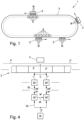
- Fig. 1 represents an exemplary long stator linear motor 1 as an electromagnetic transport system 1, which comprises a very simple transport path 3.
- transport path 3 here only represents a closed loop, transport paths 3 with any branching are of course also possible.
- a number of transport units 2 are provided, which are arranged to be movable along the transport path 1 and are moved clockwise here only as an example.
- Drive coils S are arranged along the transport path 3, whereas drive magnets M are arranged on the transport units 2. By energizing the drive coils S, a magnetic field is generated that is movable along the transport path 3 and interacts with the drive magnets M of the transport units 2 to set them in motion along the transport path 3.
- the transport path 3 can, depending on the application and requirements, be of any shape and can have closed and/or open
- the transport route 3 does not have to lie in one plane, but can also be routed anywhere in space.
- Drive coils S can also be arranged on both sides or multiple sides over at least part of the transport route 3.
- drive magnets M can be arranged on both sides or multiple sides of the transport units 2.
- the basic structure and functional principle of a long stator linear motor are well known, so they will not be discussed further here.
- a planar motor can be provided as an electromagnetic transport system 1.
- a planar motor In contrast to the long stator linear motor, which has a fundamentally one-dimensional transport path 3, a planar motor has a two-dimensional transport path 3 and can therefore also be referred to as a transport plane.
- the drive coils S are arranged distributed in the two-dimensional transport path 3 in order to generate a magnetic field which can be moved in two dimensions in the transport path 3.
- the drive magnets M are advantageously also arranged two-dimensionally distributed on the transport unit 2 in order to interact with the magnetic field and move the transport unit 2 in the transport path 3.
- the drive coils S and the drive magnets M are advantageously arranged in such a way that, in addition to a one-dimensional movement along the axes spanned by the transport path 3 (y-axis and z-axis in a yz plane), more complex two-dimensional movements of the transport unit in the transport path 3 are also possible. In principle, it is also possible for only a one-dimensional movement to be provided in the two-dimensional transport path 3. In this case, the drive magnets M and drive coils S can also be arranged in just one dimension.
- the functionality and structure of planar motors is also basically known, which is why it will not be discussed in more detail here.
- the present invention is described below fundamentally with reference to a one-dimensional transport path 3, but is also valid for other electromagnetic transport systems with two-dimensional transport paths 3, such as planar motors.
- the electromagnetic transport unit 1 can also comprise a first number of transport sections 4 that are one-dimensional and a second number of transport sections 4 that are two-dimensional.
- a flat transport path 3 is shown, which is divided into a plurality (here three) of transport sections 4, only for the purpose of easier illustration.
- the transport sections 4 are in turn divided into a number (here three) of transport segments 5, whereby the number of transport segments 5 can vary between the transport sections 4.
- a transport section 4 can also comprise branched and/or parallel transport segments 5.
- the transport segments 5 each comprise drive coils S (in Fig. 2 not shown for reasons of clarity), which are energized by a segment controller 50 associated with the transport segment 5 (each shown as coil current i) in order to generate a magnetic field traveling along the transport path 3.
- a transport segment 5 can also comprise more than one drive coil S.
- the actual values iw occurring at the transport segments 5 are known to the segment controller 50.
- the actual values iw can be, for example, the actual position and/or the actual speed and/or the actual acceleration of a transport unit 2 located in the associated transport segment 5 and/or actual currents, actual voltages, actual forces, etc. occurring in the transport segment.
- sensors e.g. (magnetic) position sensors for determining the actual position, can be provided on the transport segment 5.
- the segment controllers 50 are given setpoint values sw, whereupon manipulated variables (e.g. the coil current i or the coil voltage of the drive coils S) are specified in order to adapt the actual values iw to the setpoint values sw.
- the segment controller 50 may know operating data and/or operating parameters such as status information (identification number of the transport unit 2, mileage of the transport unit 2, maintenance data of the transport unit 2, loading status of the transport unit 2, tool number of the transport unit 2, processing sequence, data on a product loaded on the transport unit 2, etc.).
- status information identification number of the transport unit 2, mileage of the transport unit 2, maintenance data of the transport unit 2, loading status of the transport unit 2, tool number of the transport unit 2, processing sequence, data on a product loaded on the transport unit 2, etc.
- a central path planning unit is often provided for calculating and specifying the overall path and thus setpoint values, which transmits the setpoint values to all segment controllers 50 in order to generate the desired path.
- each transport section 4 is assigned a section control unit 40.
- the section control unit 40 can be designed, for example, as a programmable logic controller (PLC) or as a computer.
- a central logistics unit 30 is provided, which specifies a destination Z of the transport units 2 to the associated section control units 40 via a logistics network 34.
- further logistics functions can also be specified to the section control units 40 by the logistics unit 30 via the logistics network 34, e.g. actions to be carried out such as loading activities, etc. These logistics functions can also be carried out depending on operating data and/or operating parameters of the respective transport unit.
- the logistics unit 30 can specify to the transport sections 4 from which transport section 4 the transport unit 2 is to be transferred to which transport section 4.
- the destination Z of the respective transport units 2 can also be determined depending on the operating parameters/operating data. This allows a section control unit 40 to be controlled depending on the associated Operating parameters/operating data decide to which transport section a transport unit 2 is to be handed over without the logistics unit 30 having to intervene.
- the logistics unit 30 controls the movement of the transport units 2 by specifying the destination Z to the section control units 40.
- the section control units 40 use the target Z specified by the logistics unit 30 to determine track sections BA of the individual transport units 2 that are located within the associated transport section 4.
- the track section BA corresponds to a movement profile and can extend to an adjacent transport section 4. From the adjacent transport section 4, the associated track section BA can in turn be further planned by the associated section control unit 40. A continuous transition of the track sections BA between adjacent transport sections 4 can preferably be provided.
- Target values sw for transport units 2 located in the transport section 4 are determined using the track section BA and transmitted to the associated segment controllers 50 via a segment network 45.
- the target values sw can be, for example, the target position and/or the target speed and/or the target acceleration for a transport unit 2 located in the associated transport segment 5 and/or target currents, target forces, etc.
- the individual setpoints sw in Fig. 2 although they have the same reference symbol, they are of course not identical as a rule, but are determined individually by the section control units 40.
- the coil currents i are also not identical as a rule despite having the same reference symbol, but rather depend on the respective target values sw.
- the target Z specified by the logistics unit 3 is fundamentally the same for all section control units 40, although a distinction can of course be made between targets Z of individual transport units 2.
- the cycle time of the segment network 45 is adjustable and can be adapted to the size of the respective transport section 40 and the number of subordinate transport segments.
- the logistics unit 30 can also specify logistics functions in order to specify further process steps. These logistics functions can be transferred to the section control units 40 in the form of configurations, for example. which can then, when calculating the track section BA of the transport units 2, e.g. depending on operating parameters/operating data, instruct the transport units 2 to carry out the logistics functions.
- the section control units 40 are connected to one another via a section network 44, whereby data can be transferred between the section control units 40.
- data in particular actual values iw and/or known operating data and/or operating parameters can be transmitted via the section network 44, in particular to neighboring section control units 40.
- actual values iw and/or known operating data and/or operating parameters are transmitted from the segment control units 50 to the higher-level section control units 40 via the segment network 45.
- the section network 44 and the segment networks 45 are shown as individual connections, but they can of course also be designed as a bus, etc.
- Transport units 2 can be moved along the transport route 3, whereby different transport sections 2 can also be passed or reached. In this way, the transport unit 2 is transferred between transport sections.
- data can be transferred from a section control unit 40, which is associated with a transferring transport section 4, to a section control unit 40, which is associated with a receiving transport section 4, in order to ensure a safe transfer and takeover of the transport unit 2.
- a transfer of a transport unit 2 from a first transport section 4' to a second transport section 4" is shown, wherein only a first transport segment 5' of the first transport section 4' and a second transport segment 5" of the second transport section 4" are shown.
- the transport unit 2 is located in a transfer area U, which overlaps the first and second transport segments 5', 5" and thus also the first and second transport sections 4', 4".
- the first transport section 4' is assigned a first section control unit 40', which is connected to a first segment controller 50' assigned to the first transport segment 5' via a first segment network 45'
- the second transport section 4" is assigned a second section control unit 40" which is connected to a second segment controller 50" assigned to the second transport segment 5" via a second segment network 45".
- the transport unit 2 can be controlled in the transfer area U by the segment controllers 50'50" of both transport sections 4 ⁇ , 4" or initially by the first segment controller 50' and then by the second segment controller 50". In both cases, the first Section control unit 4' determines the first setpoint sw' based on the target Z and transmits it to the first segment controller 50'.
- the segment controller 50' provides the transport segment 5 with a control variable for energizing the drive coil(s) of the first transport segment 5' based on the received first setpoint sw' and a present first actual value iw ⁇ (e.g. determined using sensors).
- a first coil current i' is provided as a control variable, but other control variables such as coil voltages etc. are also possible.
- the calculation of the first setpoint sw' can be terminated.
- an actual value iw and/or operating data/operating parameters are transferred from the first transport section 4' to the second transport section 4".
- the actual value iw 'and/or operating data/operating parameters are transmitted from the first segment controller 50' via the first segment network 45' to the first section control unit 40', which transmits the actual value iw' via the section network 44 to the second section control unit 40".
- the change of the controlling segment controller 50 ⁇ , 50" can take place by the first segment controller 50' transmitting the first actual value iw ⁇ to its section control unit 40 ⁇ , which in turn transmits the first actual value iw ⁇ to the second section control unit 40 ⁇ via a section network 44, which can also transmit this to the second segment controller 50". Since the first actual value iw ⁇ of the second section control unit 40" is known in advance, the transport unit 2 can be quickly transferred to the second transport section 4".
- the second section control unit 40" can prepare the second setpoint value sw" based on the first actual value iw ⁇ in advance for the takeover of the transport unit 2.
- the second transport controller 50" can thus use the second setpoint value sw" to specify the corresponding second manipulated variable (e.g. the second coil current i") in order to adapt the second actual value iw" to the second setpoint value sw", and to immediately specify the second manipulated variable upon transfer.
- the path section BA is then calculated by the second section control unit 40" on the basis of the target, the second setpoint value sw" is determined, and specified to the second segment controller 50", which further specifies the second manipulated variable in order to adapt the second actual value iw" to the second setpoint value sw".
- the actual value iw ⁇ can be converted to an actual value iw" suitable for the second transport segment 5", if necessary. This can be done on the first section control unit 40' before the actual transfer of the actual value iw ⁇ via the section network 44 or on the second section control unit 40" after receiving the actual value iw ⁇ .
- the track section BA can be deleted in the first section control unit 40', since a track section BA has already been generated in the second section control unit 40".
- the fact that a transport unit 2 is arriving on the second transport section 4" can be communicated to the second section control unit 40" via the logistics network 34 by the logistics unit 30 and/or via the section network 44 by the first section control unit 40'.
- the second section control unit 40" can thus prepare to receive the transport unit 2.
- the position and/or speed of the arriving transport unit 2 can be communicated to the second section control unit 40" via the logistics network 34 by the logistics unit 30 and/or via the section network 44 by the first section control unit 40'.
- the second actual value iw" is of course already known to the second section control unit 40", with which it can directly calculate the second track section BA and from this the target value sw" and transmit it to the second segment controller 50". If the actual value iw ⁇ is also transferred to the second section control unit 40" via the section network 44 and the actual value iw" of the second segment controller 50" is already available at the second section control unit 4", this can be regarded as redundant information, with which, for example, errors can be detected.
- the transport unit 2 can be at a standstill during the transfer. However, the transfer can also take place at any speed of the transport unit 2.
- the drive coils S of the drive segments 4 located in the area of the branch apply forces in the transverse direction in addition to propulsion forces in order to repel and/or attract the transport unit 2 in such a way that the branch provided according to the determined track section BA is taken.
- the logistics unit 30 and/or section control units 40 and/or segment controllers 50 can comprise microprocessor-based hardware, for example a computer or digital signal processor (DSP), on which corresponding software is executed to carry out the respective function.
- the logistics unit 30 and/or section control units 40 and/or segment controllers 50 can also comprise an integrated circuit, for example an application-specific integrated circuit (ASIC) or a field programmable gate array (FPGA), also with a microprocessor.
- ASIC application-specific integrated circuit
- FPGA field programmable gate array
- the logistics unit 30 and/or section control units 40 and/or segment controllers 50 can also include an analog circuit or analog computer. Mixed forms are also conceivable. It is also possible for different functions to be implemented on the same hardware
Landscapes
- Engineering & Computer Science (AREA)
- Power Engineering (AREA)
- Transportation (AREA)
- Mechanical Engineering (AREA)
- Physics & Mathematics (AREA)
- Electromagnetism (AREA)
- Computer Networks & Wireless Communication (AREA)
- Signal Processing (AREA)
- General Engineering & Computer Science (AREA)
- Manufacturing & Machinery (AREA)
- Quality & Reliability (AREA)
- General Physics & Mathematics (AREA)
- Automation & Control Theory (AREA)
- Control Of Position, Course, Altitude, Or Attitude Of Moving Bodies (AREA)
- Non-Mechanical Conveyors (AREA)
- Control Of Position Or Direction (AREA)
- Control Of Linear Motors (AREA)
- Control Of Conveyors (AREA)
Claims (16)
- Système de transport électromagnétique (1), comprenant un certain nombre d'unités de transport (2) qui sont agencées de manière mobile le long d'une voie de transport (3), dans lequel des bobines d'entraînement (S) sont agencées le long de la voie de transport (3), et des aimants d'entraînement (M) sont agencés sur les unités de transport (2),dans lequel la voie de transport (3) est divisée en sections de transport (4) et les sections de transport (4) comprennent respectivement au moins un segment de transport (5), dans lequel respectivement une unité de commande de section (40) est associée aux sections de transport (4), et respectivement un régulateur de segment (50) est associé aux segments de transport (5),caractérisé en ce qu'une unité logistique (30) est prévue qui est reliée aux unités de commande de section (40) par l'intermédiaire d'un réseau logistique (34), et qui est configurée pour spécifier aux unités de commande de section (40) une destination (Z) du nombre d'unités de transport (2) par l'intermédiaire du réseau logistique (34),en ce que les unités de commande de section (40) des sections de transport (4) sont reliées par l'intermédiaire d'un réseau de segments (45) aux régulateurs de segment (50) des segments de transport (5) associés et sont configuréeset en ce que les régulateurs de segment (50) sont configurés pour alimenter en courant les bobines d'entraînement en utilisant les valeurs de consigne (sw) et des valeurs réelles (iw) qui apparaissent afin de générer un champ magnétique interagissant avec les aimants d'entraînement (M) des unités de transport (2) afin de déplacer le nombre d'unités de transport (2).- pour établir à partir de la destination (Z) pour la section de transport (4) associée une section de trajectoire (BA) pour les unités de transport (2) se trouvant dans la section de transport (4) associée, dans lequel une section de trajectoire (BA) décrit un itinéraire général d'un emplacement actuel des unités de transport (2) jusqu'à une position de transfert entre des sections de transport (4) voisines dans la mesure où la destination (Z) est située à l'extérieur de la section de transport (4), ou décrit la destination (Z) dans la mesure où la destination (Z) se situe à l'intérieur de la section de transport (4),- pour établir des valeurs de consigne (sw) pour les unités de transport (2) se trouvant dans la section de transport (4) associée en utilisant la section de trajectoire (BA),- et pour transmettre les valeurs de consigne (sw) par l'intermédiaire du réseau de segments (45) aux régulateurs de segment (50) associés,
- Système de transport électromagnétique (1) selon la revendication 1, caractérisé en ce que des capteurs sont prévus sur les segments de transport (5) afin de détecter les valeurs réelles (iw).
- Système de transport électromagnétique (1) selon la revendication 1 ou 2, caractérisé en ce que les valeurs réelles (iw) comprennent des courants réels et/ou des forces réelles et/ou des positions réelles et/ou des vitesses réelles et/ou des accélérations réelles, et en ce que les valeurs de consigne (sw) comprennent des courants de consigne et/ou des forces de consigne et/ou des positions de consigne et/ou des vitesses de consigne et/ou des accélérations de consigne.
- Système de transport électromagnétique (1) selon l'une quelconque des revendications 1 à 3, caractérisé en ce que les unités de commande de section (40) sont reliées les unes aux autres par l'intermédiaire d'un réseau de sections (44) et sont configurées pour transmettre des données, de préférence des valeurs réelles (iw), par l'intermédiaire du réseau de sections (44) .
- Système de transport électromagnétique (1) selon la revendication 4, caractérisé en ce que le réseau de sections (44) représente un réseau en temps réel ou un réseau de point à point, de préférence avec un temps de cycle réglable.
- Système de transport électromagnétique (1) selon l'une quelconque des revendications 1 à 5, caractérisé en ce que le réseau de segments (45) représente un réseau en temps réel, de préférence avec un temps de cycle réglable.
- Système de transport électromagnétique (1) selon l'une quelconque des revendications 1 à 6, caractérisé en ce que le réseau logistique (34) est un réseau non compatible en temps réel, de préférence un réseau Ethernet.
- Système de transport électromagnétique (1) selon l'une quelconque des revendications 1 à 7, caractérisé en ce que des segments de transport voisins (5) sont réalisés en se chevauchant.
- Système de transport électromagnétique selon l'une quelconque des revendications 1 à 8, caractérisé en ce que les sections de transport (4) sont réalisées respectivement de manière bidimensionnelle et/ou unidimensionnelle.
- Procédé permettant de commander le mouvement d'un certain nombre d'unités de transport (2) qui sont agencées de manière mobile le long d'une voie de transport (3) d'un système de transport électromagnétique (1), dans lequel la voie de transport (3) est divisée en sections de transport (4), et les sections de transport (4) comprennent respectivement au moins un segment de transport (5),
caractérisé en ce qu'une unité logistique (30) spécifie par l'intermédiaire d'un réseau logistique (34) pour des unités de commande de section (40) associées à des sections de transport (4) respectivement une destination (Z) du nombre d'unités de transport (2), en ce que les unités de commande de section (40) établissent pour le nombre d'unités de transport (2) à partir de la destination (Z) associée pour la section de transport respectivement associée respectivement une section de trajectoire (BA) pour les unités de transport (2) se trouvant dans la section de transport (4) associée, dans lequel une section de trajectoire (BA) décrit un itinéraire général d'un emplacement actuel de l'unité de transport (2) respective à une position de transfert entre des sections de transport (4) voisines dans la mesure où la destination (Z) se trouve à l'extérieur de la section de transport (4), ou décrit la destination (Z) dans la mesure où la destination (Z) se trouve à l'intérieur de la section de transport (4), qu'elles établissent à partir des sections de trajectoire (BA) des valeurs de consigne (sw) pour les unités de transport (2) se trouvant dans la section de transport (4) associée et les transmettent par un réseau de segments (45) à des régulateurs de segment (50) des segments (5) associés, et en ce que les régulateurs de segment (50), en utilisant les valeurs de consigne (sw) et des valeurs réelles connues (iw), alimentent en courant des bobines d'entraînement (S) du segment de transport (5) pour générer un champ magnétique interagissant avec des aimants d'entraînement (M) des unités de transport (2) afin de déplacer le nombre d'unités de transport (2). - Procédé selon la revendication 10, caractérisé en ce que les unités de commande de section (4) échangent des données par l'intermédiaire d'un réseau de sections (44) .
- Procédé selon la revendication 11, caractérisé en ce que les régulateurs de segment (50) transmettent par l'intermédiaire du réseau de segments (45) des valeurs réelles (iw) aux unités de commande de section (4), et en ce que les unités de commande de section (4) transmettent des valeurs réelles (iw) par l'intermédiaire d'un réseau de sections (44).
- Procédé selon l'une quelconque des revendications 10 à 12, caractérisé en ce que des sections de trajectoire (BA) de sections de transport (4) voisines présentent une position et/ou une vitesse et/ou une accélération constante(s) de l'unité de transport (2).
- Procédé selon l'une quelconque des revendications 10 à 13, caractérisé en ce que les régulateurs de segment (50) transmettent des paramètres de fonctionnement et/ou des données de fonctionnement aux unités de commande de section (40) associées.
- Procédé selon la revendication 14, caractérisé en ce que les unités de commande de section (40) transmettent les paramètres de fonctionnement et/ou les données de fonctionnement à l'unité logistique (30).
- Procédé selon l'une quelconque des revendications 10 à 15, caractérisé en ce que les unités de commande de section (40) établissent les valeurs de consigne (sw) en respectant des valeurs maximales prédéfinies.
Applications Claiming Priority (2)
| Application Number | Priority Date | Filing Date | Title |
|---|---|---|---|
| ATA50803/2020A AT524273A1 (de) | 2020-09-22 | 2020-09-22 | Elektromagnetisches Transportsystem |
| PCT/EP2021/076104 WO2022063848A1 (fr) | 2020-09-22 | 2021-09-22 | Système de transport électromagnétique |
Publications (2)
| Publication Number | Publication Date |
|---|---|
| EP4217807A1 EP4217807A1 (fr) | 2023-08-02 |
| EP4217807B1 true EP4217807B1 (fr) | 2024-10-30 |
Family
ID=78085624
Family Applications (1)
| Application Number | Title | Priority Date | Filing Date |
|---|---|---|---|
| EP21787310.8A Active EP4217807B1 (fr) | 2020-09-22 | 2021-09-22 | Système de transport électromagnétique |
Country Status (6)
| Country | Link |
|---|---|
| US (1) | US12151905B2 (fr) |
| EP (1) | EP4217807B1 (fr) |
| JP (1) | JP2023546331A (fr) |
| CN (1) | CN116209962B (fr) |
| AT (1) | AT524273A1 (fr) |
| WO (1) | WO2022063848A1 (fr) |
Families Citing this family (5)
| Publication number | Priority date | Publication date | Assignee | Title |
|---|---|---|---|---|
| US20240059327A1 (en) * | 2022-08-16 | 2024-02-22 | Rockwell Automation Technologies, Inc. | System and Method for Mover Self-Navigation in an Independent Cart System |
| EP4332029A1 (fr) | 2022-08-30 | 2024-03-06 | Siemens Aktiengesellschaft | Système de transport de marchandises, unité de commande, kit, produit programme de simulation et utilisation d'un composant actif d'un moteur plan |
| WO2024100880A1 (fr) * | 2022-11-11 | 2024-05-16 | 三菱電機株式会社 | Système de transport |
| EP4382458A1 (fr) * | 2022-12-08 | 2024-06-12 | Robert Bosch GmbH | Procédé de commande du mouvement d'au moins un élément mobile sur un système de transport |
| CN119769845A (zh) * | 2024-12-30 | 2025-04-08 | 浙江蚂蚁盒子家居用品有限公司 | 基于物联网的智能折叠衣柜 |
Family Cites Families (11)
| Publication number | Priority date | Publication date | Assignee | Title |
|---|---|---|---|---|
| CN1417073A (zh) * | 2002-12-02 | 2003-05-14 | 张惠东 | 路网及运载工具系统 |
| EP3148904B1 (fr) | 2014-06-02 | 2021-05-05 | ATS Automation Tooling Systems Inc. | Système et procédé permettant de commander un élément mobile dans un convoyeur à moteur linéaire |
| EP3024128B1 (fr) | 2014-11-18 | 2018-04-25 | Siemens Aktiengesellschaft | Commande modulaire d'un entraînement linéaire avec communication |
| AT519829A1 (de) * | 2017-04-04 | 2018-10-15 | B & R Ind Automation Gmbh | Verfahren zum Betreiben eines Langstatorlinearmotors |
| US10442637B2 (en) * | 2017-09-21 | 2019-10-15 | Magnemotion, Inc. | Linear drive system having central, distributed and group control |
| US10608469B2 (en) * | 2017-09-28 | 2020-03-31 | Rockwell Automation Technologies, Inc. | Method and apparatus for power transfer to an independent moving cart during travel along a track |
| EP3599126B1 (fr) * | 2018-07-25 | 2021-11-10 | B&R Industrial Automation GmbH | Procédé de fonctionnement d'un moteur linéaire à stator long pourvu d'aiguillage |
| US10587212B1 (en) * | 2018-11-12 | 2020-03-10 | Rockwell Automation Technologies, Inc. | Linear motor track system with automatic gravity detection |
| EP3653428A1 (fr) * | 2018-11-19 | 2020-05-20 | B&R Industrial Automation GmbH | Procédé de surveillance sûre du fonctionnement d'un moteur linéaire à stator long |
| EP3661033A1 (fr) * | 2018-11-27 | 2020-06-03 | B&R Industrial Automation GmbH | Dispositif de transport sous forme d'un moteur linéaire à stator long |
| JP2021090343A (ja) * | 2019-12-03 | 2021-06-10 | ベーウントエル・インダストリアル・オートメイション・ゲゼルシャフト・ミト・ベシュレンクテル・ハフツング | 安全機能 |
-
2020
- 2020-09-22 AT ATA50803/2020A patent/AT524273A1/de unknown
-
2021
- 2021-09-22 WO PCT/EP2021/076104 patent/WO2022063848A1/fr not_active Ceased
- 2021-09-22 US US18/025,086 patent/US12151905B2/en active Active
- 2021-09-22 CN CN202180064357.4A patent/CN116209962B/zh active Active
- 2021-09-22 JP JP2023518180A patent/JP2023546331A/ja active Pending
- 2021-09-22 EP EP21787310.8A patent/EP4217807B1/fr active Active
Also Published As
| Publication number | Publication date |
|---|---|
| WO2022063848A1 (fr) | 2022-03-31 |
| CN116209962B (zh) | 2025-10-14 |
| EP4217807A1 (fr) | 2023-08-02 |
| US12151905B2 (en) | 2024-11-26 |
| AT524273A1 (de) | 2022-04-15 |
| CN116209962A (zh) | 2023-06-02 |
| JP2023546331A (ja) | 2023-11-02 |
| US20230322506A1 (en) | 2023-10-12 |
Similar Documents
| Publication | Publication Date | Title |
|---|---|---|
| EP4217807B1 (fr) | Système de transport électromagnétique | |
| EP3422558B1 (fr) | Moteur linéaire à stator long et procédé de déplacement d'une unité de transport d'un moteur linéaire à stator long | |
| EP3251986B1 (fr) | Procédé de fonctionnement d'un moteur linéaire à stator déployé | |
| EP3202612B1 (fr) | Procédé de fonctionnement d'un dispositif de transport en forme de moteur linéaire à stator long | |
| EP3341803B1 (fr) | Procédé de commande et/ou de régulation d'un dispositif d'entraînement linéaire, dispositif de commande, dispositif d'entraînement linéaire et installation | |
| EP3385803B1 (fr) | Procédé de fonctionnement d'un moteur linéaire à stator déployé | |
| AT518734B1 (de) | Verfahren zum Betreiben eines Langstatorlinearmotors | |
| DE102020135153A1 (de) | Logistikfläche und Verfahren zum Betreiben einer solchen | |
| EP3802384B1 (fr) | Procédé pour la commande d'une unité de transport d'un dispositif de transport sous la forme d'un moteur linéaire à stator long | |
| EP3567442B1 (fr) | Système de transport | |
| EP4098473A1 (fr) | Installation de transport et procédé permettant de faire fonctionner une installation de transport ayant une surveillance de collisions | |
| EP3162742B1 (fr) | Systeme de tri ayant une commande distribuee | |
| EP3061576A1 (fr) | Procédé d'optimisation d'un profil de mouvement, programme informatique, dispositif de commande et système technique | |
| EP4147102B1 (fr) | Fonctionnement d'une machine-outil au moins à deux axes | |
| WO2018041604A1 (fr) | Machine de traitement comprenant plusieurs postes de traitement pour le traitement de corps | |
| EP4591426B1 (fr) | Procédé de fonctionnement d'un système d'entraînement plan, et système d'entraînement plan | |
| EP4558946B1 (fr) | Système de stockage et de préparation de commandes à flux de matériel optimisé | |
| DE102021101354A1 (de) | Modulares Montagesystem sowie Verfahren zum Betreiben des modularen Montagesystems | |
| EP1795487B1 (fr) | Méthode de pré-assemblage pour un escalier roulant ou trottoir roulant et ligne d'assemblage correspondant. | |
| DE102010032869A1 (de) | Verfahren zum Betreiben einer Produktionsanlage | |
| DE102017214073A1 (de) | Bearbeitungsmaschine mit mehreren Bearbeitungsstationen zum Bearbeiten von Körpern | |
| DE102016217376B4 (de) | Bearbeitungsmaschine mit mehreren Bearbeitungsstationen zum Bearbeiten von Körpern | |
| EP4526745A1 (fr) | Procédé de commande du mouvement d'un axe d'entraînement d'une unité d'entraînement | |
| DD289354A5 (de) | Schaltungsanordnung zur folgesteuerung an bahnabschnittsuebergaengen |
Legal Events
| Date | Code | Title | Description |
|---|---|---|---|
| STAA | Information on the status of an ep patent application or granted ep patent |
Free format text: STATUS: UNKNOWN |
|
| STAA | Information on the status of an ep patent application or granted ep patent |
Free format text: STATUS: THE INTERNATIONAL PUBLICATION HAS BEEN MADE |
|
| PUAI | Public reference made under article 153(3) epc to a published international application that has entered the european phase |
Free format text: ORIGINAL CODE: 0009012 |
|
| STAA | Information on the status of an ep patent application or granted ep patent |
Free format text: STATUS: REQUEST FOR EXAMINATION WAS MADE |
|
| 17P | Request for examination filed |
Effective date: 20230202 |
|
| AK | Designated contracting states |
Kind code of ref document: A1 Designated state(s): AL AT BE BG CH CY CZ DE DK EE ES FI FR GB GR HR HU IE IS IT LI LT LU LV MC MK MT NL NO PL PT RO RS SE SI SK SM TR |
|
| DAV | Request for validation of the european patent (deleted) | ||
| DAX | Request for extension of the european patent (deleted) | ||
| GRAP | Despatch of communication of intention to grant a patent |
Free format text: ORIGINAL CODE: EPIDOSNIGR1 |
|
| STAA | Information on the status of an ep patent application or granted ep patent |
Free format text: STATUS: GRANT OF PATENT IS INTENDED |
|
| RIC1 | Information provided on ipc code assigned before grant |
Ipc: B65G 54/02 20060101ALN20240412BHEP Ipc: B60L 13/08 20060101ALI20240412BHEP Ipc: B60L 15/38 20060101ALI20240412BHEP Ipc: B60L 13/03 20060101ALI20240412BHEP Ipc: G05B 19/418 20060101AFI20240412BHEP |
|
| INTG | Intention to grant announced |
Effective date: 20240510 |
|
| GRAS | Grant fee paid |
Free format text: ORIGINAL CODE: EPIDOSNIGR3 |
|
| GRAA | (expected) grant |
Free format text: ORIGINAL CODE: 0009210 |
|
| STAA | Information on the status of an ep patent application or granted ep patent |
Free format text: STATUS: THE PATENT HAS BEEN GRANTED |
|
| P01 | Opt-out of the competence of the unified patent court (upc) registered |
Free format text: CASE NUMBER: APP_50181/2024 Effective date: 20240904 |
|
| AK | Designated contracting states |
Kind code of ref document: B1 Designated state(s): AL AT BE BG CH CY CZ DE DK EE ES FI FR GB GR HR HU IE IS IT LI LT LU LV MC MK MT NL NO PL PT RO RS SE SI SK SM TR |
|
| REG | Reference to a national code |
Ref country code: GB Ref legal event code: FG4D Free format text: NOT ENGLISH |
|
| REG | Reference to a national code |
Ref country code: CH Ref legal event code: EP |
|
| REG | Reference to a national code |
Ref country code: IE Ref legal event code: FG4D Free format text: LANGUAGE OF EP DOCUMENT: GERMAN |
|
| REG | Reference to a national code |
Ref country code: DE Ref legal event code: R096 Ref document number: 502021005657 Country of ref document: DE |
|
| REG | Reference to a national code |
Ref country code: LT Ref legal event code: MG9D |
|
| REG | Reference to a national code |
Ref country code: NL Ref legal event code: MP Effective date: 20241030 |
|
| RAP2 | Party data changed (patent owner data changed or rights of a patent transferred) |
Owner name: ABB SCHWEIZ AG |
|
| PG25 | Lapsed in a contracting state [announced via postgrant information from national office to epo] |
Ref country code: PT Free format text: LAPSE BECAUSE OF FAILURE TO SUBMIT A TRANSLATION OF THE DESCRIPTION OR TO PAY THE FEE WITHIN THE PRESCRIBED TIME-LIMIT Effective date: 20250228 Ref country code: IS Free format text: LAPSE BECAUSE OF FAILURE TO SUBMIT A TRANSLATION OF THE DESCRIPTION OR TO PAY THE FEE WITHIN THE PRESCRIBED TIME-LIMIT Effective date: 20250228 Ref country code: HR Free format text: LAPSE BECAUSE OF FAILURE TO SUBMIT A TRANSLATION OF THE DESCRIPTION OR TO PAY THE FEE WITHIN THE PRESCRIBED TIME-LIMIT Effective date: 20241030 |
|
| PG25 | Lapsed in a contracting state [announced via postgrant information from national office to epo] |
Ref country code: NL Free format text: LAPSE BECAUSE OF FAILURE TO SUBMIT A TRANSLATION OF THE DESCRIPTION OR TO PAY THE FEE WITHIN THE PRESCRIBED TIME-LIMIT Effective date: 20241030 Ref country code: FI Free format text: LAPSE BECAUSE OF FAILURE TO SUBMIT A TRANSLATION OF THE DESCRIPTION OR TO PAY THE FEE WITHIN THE PRESCRIBED TIME-LIMIT Effective date: 20241030 |
|
| PG25 | Lapsed in a contracting state [announced via postgrant information from national office to epo] |
Ref country code: BG Free format text: LAPSE BECAUSE OF FAILURE TO SUBMIT A TRANSLATION OF THE DESCRIPTION OR TO PAY THE FEE WITHIN THE PRESCRIBED TIME-LIMIT Effective date: 20241030 |
|
| PG25 | Lapsed in a contracting state [announced via postgrant information from national office to epo] |
Ref country code: ES Free format text: LAPSE BECAUSE OF FAILURE TO SUBMIT A TRANSLATION OF THE DESCRIPTION OR TO PAY THE FEE WITHIN THE PRESCRIBED TIME-LIMIT Effective date: 20241030 |
|
| PG25 | Lapsed in a contracting state [announced via postgrant information from national office to epo] |
Ref country code: NO Free format text: LAPSE BECAUSE OF FAILURE TO SUBMIT A TRANSLATION OF THE DESCRIPTION OR TO PAY THE FEE WITHIN THE PRESCRIBED TIME-LIMIT Effective date: 20250130 |
|
| PG25 | Lapsed in a contracting state [announced via postgrant information from national office to epo] |
Ref country code: GR Free format text: LAPSE BECAUSE OF FAILURE TO SUBMIT A TRANSLATION OF THE DESCRIPTION OR TO PAY THE FEE WITHIN THE PRESCRIBED TIME-LIMIT Effective date: 20250131 Ref country code: LV Free format text: LAPSE BECAUSE OF FAILURE TO SUBMIT A TRANSLATION OF THE DESCRIPTION OR TO PAY THE FEE WITHIN THE PRESCRIBED TIME-LIMIT Effective date: 20241030 |
|
| PG25 | Lapsed in a contracting state [announced via postgrant information from national office to epo] |
Ref country code: PL Free format text: LAPSE BECAUSE OF FAILURE TO SUBMIT A TRANSLATION OF THE DESCRIPTION OR TO PAY THE FEE WITHIN THE PRESCRIBED TIME-LIMIT Effective date: 20241030 |
|
| PG25 | Lapsed in a contracting state [announced via postgrant information from national office to epo] |
Ref country code: RS Free format text: LAPSE BECAUSE OF FAILURE TO SUBMIT A TRANSLATION OF THE DESCRIPTION OR TO PAY THE FEE WITHIN THE PRESCRIBED TIME-LIMIT Effective date: 20250130 |
|
| REG | Reference to a national code |
Ref country code: DE Ref legal event code: R081 Ref document number: 502021005657 Country of ref document: DE Owner name: ABB SCHWEIZ AG, CH Free format text: FORMER OWNER: B&R INDUSTRIAL AUTOMATION GMBH, EGGELSBERG, AT |
|
| PG25 | Lapsed in a contracting state [announced via postgrant information from national office to epo] |
Ref country code: SM Free format text: LAPSE BECAUSE OF FAILURE TO SUBMIT A TRANSLATION OF THE DESCRIPTION OR TO PAY THE FEE WITHIN THE PRESCRIBED TIME-LIMIT Effective date: 20241030 |
|
| PG25 | Lapsed in a contracting state [announced via postgrant information from national office to epo] |
Ref country code: DK Free format text: LAPSE BECAUSE OF FAILURE TO SUBMIT A TRANSLATION OF THE DESCRIPTION OR TO PAY THE FEE WITHIN THE PRESCRIBED TIME-LIMIT Effective date: 20241030 |
|
| PG25 | Lapsed in a contracting state [announced via postgrant information from national office to epo] |
Ref country code: EE Free format text: LAPSE BECAUSE OF FAILURE TO SUBMIT A TRANSLATION OF THE DESCRIPTION OR TO PAY THE FEE WITHIN THE PRESCRIBED TIME-LIMIT Effective date: 20241030 |
|
| PG25 | Lapsed in a contracting state [announced via postgrant information from national office to epo] |
Ref country code: RO Free format text: LAPSE BECAUSE OF FAILURE TO SUBMIT A TRANSLATION OF THE DESCRIPTION OR TO PAY THE FEE WITHIN THE PRESCRIBED TIME-LIMIT Effective date: 20241030 |
|
| PG25 | Lapsed in a contracting state [announced via postgrant information from national office to epo] |
Ref country code: SK Free format text: LAPSE BECAUSE OF FAILURE TO SUBMIT A TRANSLATION OF THE DESCRIPTION OR TO PAY THE FEE WITHIN THE PRESCRIBED TIME-LIMIT Effective date: 20241030 |
|
| PG25 | Lapsed in a contracting state [announced via postgrant information from national office to epo] |
Ref country code: CZ Free format text: LAPSE BECAUSE OF FAILURE TO SUBMIT A TRANSLATION OF THE DESCRIPTION OR TO PAY THE FEE WITHIN THE PRESCRIBED TIME-LIMIT Effective date: 20241030 |
|
| REG | Reference to a national code |
Ref country code: DE Ref legal event code: R097 Ref document number: 502021005657 Country of ref document: DE |
|
| PLBE | No opposition filed within time limit |
Free format text: ORIGINAL CODE: 0009261 |
|
| STAA | Information on the status of an ep patent application or granted ep patent |
Free format text: STATUS: NO OPPOSITION FILED WITHIN TIME LIMIT |
|
| PG25 | Lapsed in a contracting state [announced via postgrant information from national office to epo] |
Ref country code: SE Free format text: LAPSE BECAUSE OF FAILURE TO SUBMIT A TRANSLATION OF THE DESCRIPTION OR TO PAY THE FEE WITHIN THE PRESCRIBED TIME-LIMIT Effective date: 20241030 |
|
| 26N | No opposition filed |
Effective date: 20250731 |
|
| PGFP | Annual fee paid to national office [announced via postgrant information from national office to epo] |
Ref country code: DE Payment date: 20250919 Year of fee payment: 5 |
|
| PGFP | Annual fee paid to national office [announced via postgrant information from national office to epo] |
Ref country code: IT Payment date: 20250923 Year of fee payment: 5 |
|
| PGFP | Annual fee paid to national office [announced via postgrant information from national office to epo] |
Ref country code: FR Payment date: 20250922 Year of fee payment: 5 Ref country code: AT Payment date: 20251020 Year of fee payment: 5 |
|
| REG | Reference to a national code |
Ref country code: CH Ref legal event code: H13 Free format text: ST27 STATUS EVENT CODE: U-0-0-H10-H13 (AS PROVIDED BY THE NATIONAL OFFICE) Effective date: 20260425 |