EP4218363B1 - Procédé de dispositif de cuisson par induction sans zone et dispositif de commande - Google Patents
Procédé de dispositif de cuisson par induction sans zone et dispositif de commande Download PDFInfo
- Publication number
- EP4218363B1 EP4218363B1 EP20765008.6A EP20765008A EP4218363B1 EP 4218363 B1 EP4218363 B1 EP 4218363B1 EP 20765008 A EP20765008 A EP 20765008A EP 4218363 B1 EP4218363 B1 EP 4218363B1
- Authority
- EP
- European Patent Office
- Prior art keywords
- induction coil
- induction
- response
- detection signal
- response signal
- Prior art date
- Legal status (The legal status is an assumption and is not a legal conclusion. Google has not performed a legal analysis and makes no representation as to the accuracy of the status listed.)
- Active
Links
Images




Classifications
-
- H—ELECTRICITY
- H05—ELECTRIC TECHNIQUES NOT OTHERWISE PROVIDED FOR
- H05B—ELECTRIC HEATING; ELECTRIC LIGHT SOURCES NOT OTHERWISE PROVIDED FOR; CIRCUIT ARRANGEMENTS FOR ELECTRIC LIGHT SOURCES, IN GENERAL
- H05B6/00—Heating by electric, magnetic or electromagnetic fields
- H05B6/02—Induction heating
- H05B6/06—Control, e.g. of temperature, of power
- H05B6/062—Control, e.g. of temperature, of power for cooking plates or the like
-
- H—ELECTRICITY
- H05—ELECTRIC TECHNIQUES NOT OTHERWISE PROVIDED FOR
- H05B—ELECTRIC HEATING; ELECTRIC LIGHT SOURCES NOT OTHERWISE PROVIDED FOR; CIRCUIT ARRANGEMENTS FOR ELECTRIC LIGHT SOURCES, IN GENERAL
- H05B6/00—Heating by electric, magnetic or electromagnetic fields
- H05B6/02—Induction heating
- H05B6/06—Control, e.g. of temperature, of power
- H05B6/062—Control, e.g. of temperature, of power for cooking plates or the like
- H05B6/065—Control, e.g. of temperature, of power for cooking plates or the like using coordinated control of multiple induction coils
-
- H—ELECTRICITY
- H05—ELECTRIC TECHNIQUES NOT OTHERWISE PROVIDED FOR
- H05B—ELECTRIC HEATING; ELECTRIC LIGHT SOURCES NOT OTHERWISE PROVIDED FOR; CIRCUIT ARRANGEMENTS FOR ELECTRIC LIGHT SOURCES, IN GENERAL
- H05B6/00—Heating by electric, magnetic or electromagnetic fields
- H05B6/02—Induction heating
- H05B6/10—Induction heating apparatus, other than furnaces, for specific applications
- H05B6/12—Cooking devices
- H05B6/1209—Cooking devices induction cooking plates or the like and devices to be used in combination with them
- H05B6/1245—Cooking devices induction cooking plates or the like and devices to be used in combination with them with special coil arrangements
- H05B6/1272—Cooking devices induction cooking plates or the like and devices to be used in combination with them with special coil arrangements with more than one coil or coil segment per heating zone
-
- H—ELECTRICITY
- H05—ELECTRIC TECHNIQUES NOT OTHERWISE PROVIDED FOR
- H05B—ELECTRIC HEATING; ELECTRIC LIGHT SOURCES NOT OTHERWISE PROVIDED FOR; CIRCUIT ARRANGEMENTS FOR ELECTRIC LIGHT SOURCES, IN GENERAL
- H05B2213/00—Aspects relating both to resistive heating and to induction heating, covered by H05B3/00 and H05B6/00
- H05B2213/03—Heating plates made out of a matrix of heating elements that can define heating areas adapted to cookware randomly placed on the heating plate
-
- H—ELECTRICITY
- H05—ELECTRIC TECHNIQUES NOT OTHERWISE PROVIDED FOR
- H05B—ELECTRIC HEATING; ELECTRIC LIGHT SOURCES NOT OTHERWISE PROVIDED FOR; CIRCUIT ARRANGEMENTS FOR ELECTRIC LIGHT SOURCES, IN GENERAL
- H05B2213/00—Aspects relating both to resistive heating and to induction heating, covered by H05B3/00 and H05B6/00
- H05B2213/05—Heating plates with pan detection means
-
- H—ELECTRICITY
- H05—ELECTRIC TECHNIQUES NOT OTHERWISE PROVIDED FOR
- H05B—ELECTRIC HEATING; ELECTRIC LIGHT SOURCES NOT OTHERWISE PROVIDED FOR; CIRCUIT ARRANGEMENTS FOR ELECTRIC LIGHT SOURCES, IN GENERAL
- H05B2213/00—Aspects relating both to resistive heating and to induction heating, covered by H05B3/00 and H05B6/00
- H05B2213/06—Cook-top or cookware capable of communicating with each other
-
- Y—GENERAL TAGGING OF NEW TECHNOLOGICAL DEVELOPMENTS; GENERAL TAGGING OF CROSS-SECTIONAL TECHNOLOGIES SPANNING OVER SEVERAL SECTIONS OF THE IPC; TECHNICAL SUBJECTS COVERED BY FORMER USPC CROSS-REFERENCE ART COLLECTIONS [XRACs] AND DIGESTS
- Y02—TECHNOLOGIES OR APPLICATIONS FOR MITIGATION OR ADAPTATION AGAINST CLIMATE CHANGE
- Y02B—CLIMATE CHANGE MITIGATION TECHNOLOGIES RELATED TO BUILDINGS, e.g. HOUSING, HOUSE APPLIANCES OR RELATED END-USER APPLICATIONS
- Y02B40/00—Technologies aiming at improving the efficiency of home appliances, e.g. induction cooking or efficient technologies for refrigerators, freezers or dish washers
Definitions
- the present disclosure relates to a method of controlling a zone-free induction cooker and a controller for controlling a zone-free induction cooker.
- induction cooktops or cookers There are two general arrangements of induction cooktops or cookers, which are distinguished by the number and placement of the induction coils.
- a cooking surface e.g. a glass surface
- Cooking vessels may be placed on the cooking surface where they can be heated by one or more (depending on the arrangement) of the induction coils using electromagnetic induction, as known in the art.
- Cooking vessels suitable for inductive heating include, e.g., cooking vessels made from or containing ferromagnetic material.
- a small number e.g. four
- Each induction coil defines a specific "hob area”.
- a cooking vessel can only be heated if it is placed substantially in one of these hob areas. This requires a user to be careful with the cooking vessel placement and also limits the number of cooking vessels which can be placed on the cooker.
- induction coils typically cover the entire cooking surface, meaning that a cooking vessel can be placed practically anywhere on the cooking surface, without restriction to specific hob areas. The cooking vessel will then be heated inductively by whichever one or more (typically more) induction coils above which it is located.
- Sensing devices such as optical, capacitive, and ultrasonic sensors, are typically provided for detecting the position of the cooking vessel(s) so that the corresponding induction coils can be powered accordingly.
- EP 2 779 787 A1 discloses a method of controlling an induction cooker according to the preamble of claim 1 and a controller for an induction cooker according to the preamble of claim 9.
- a method of controlling an induction cooker comprising at least two induction coils for inductively heating cooking vessels, the method comprising: providing a detection signal to a first of said induction coils; providing a detection signal to a second of said induction coils; and measuring a response signal from the first induction coil; and identifying that the response signal from the first induction coil includes an indication of a response signal generated at the second induction coil in response to the detection signal provided to the second induction coil, thereby to determine that a same cooking vessel occupies both the first induction coil and the second induction coil.
- the detection signal provided to the second induction coil is provided at a later time than the detection signal is provided to the first induction coil, and the indication of the response signal generated at the second induction coil is an increase in the amplitude of the response signal from the first induction coil at a point in time corresponding to the time at which the detection signal was provided to the second induction coil.
- the detection signal provided to the second induction coil has a frequency different from that of the detection signal provided to the first induction coil, and the indication of the response signal generated at the second induction coil is a sum of the response signal from the first induction coil and the response signal from the second induction coil.
- the method comprises measuring the response signal from the second induction coil; and wherein said identifying is performed in response to both the response signals being damped.
- a response signal from an induction coil will be damped due to the presence of (at least part of) a cooking vessel occupying the induction coil.
- the method comprises, in response to determining that a same cooking vessel occupies both the first and second induction coils, assigning the first and second induction coils to the same control zone so that the first and second induction coils are controlled by a single control setting.
- the method comprises: measuring the response signal from the second induction coil; identifying that both the response signals are damped but there is no indication of a response signal generated at the second induction coil in response to the second detection signal, to thereby determine that two separate cooking vessels occupy the first and second induction coils respectively; and, in response to determining that two separate vessels occupy the first and second induction coils respectively, assigning each of the first and second induction coils to separate control zones so that the first and second induction coils are controlled by different respective control settings.
- the induction cooker comprises at least three induction coils
- the method comprises: providing a detection signal to a third of said induction coils to cause the third induction coil to generate a response signal; and identifying that the response signal from the first induction coil includes an indication of a response signal generated at the third induction coil in response to the detection signal provided to the third induction coil, thereby to determine that a same cooking vessel occupies both the first induction coil and the third induction coil.
- the detection signal provided to the third induction coil is provided at a later time than the detection signals are provided to the first and second induction coils, and the indication of the response signal generated at the third induction coil is an increase in the amplitude of the response signal from the first induction coil at a point in time corresponding to the time at which the detection signal was provided to the third induction coil.
- a controller for an induction cooker comprising at least two induction coils for inductively heating cooking vessels, the controller being configured so as when installed at an induction cooker to: provide a detection signal to a first of said induction coils; provide a detection signal to a second of said induction coils; measure a response signal from the first induction coil; and identify whether the response signal from the first induction coil includes an indication of a response signal generated at the second induction coil in response to the second detection signal, thereby to determine that a same cooking vessel occupies both the first induction coil and the second induction coil.
- the controller is configured to provide the detection signal to the second induction coil at a later time than the detection signal to the first induction coil, and the indication of the response signal generated at the second induction coil is an increase in the amplitude of the response signal from the first induction coil at a point in time corresponding to the time at which the detection signal was provided to the second induction coil.
- the detection signal provided to the second induction coil has a frequency different from that of the detection signal provided to the first induction coil, and the indication of the response signal generated at the second induction coil is a sum of the response signal from the first induction coil and the response signal from the second induction coil.
- the controller is configured to measure the response signal from the second induction coil; and wherein the controller is configured to perform said identifying in response to both the response signals being damped.
- the controller is configured to, in response to determining that a same cooking vessel occupies both the first and second induction coils, assign the first and second induction coils to the same control zone so that the first and second induction coils are controlled by a single control setting.
- the induction cooker comprises at least three induction coils
- the controller is configured to: provide a detection signal to a third of said induction coils to cause the third induction coil to generate a response signal; and identify that the response signal from the first induction coil includes an indication of a response signal generated at the third induction coil in response to the detection signal provided to the third induction coil, thereby to determine that a same cooking vessel occupies both the first induction coil and the third induction coil.
- an induction cooker comprising the controller according to the second aspect and a plurality of induction coils.
- Figure 1 shows an example of an induction cooker 100 in accordance with the present disclosure.
- the induction cooker 100 may be referred to as a "zone-free” or “free-zone” induction cooker.
- the induction cooker 100 comprises a plurality of induction coils 200 and a controller 300.
- a cooking surface e.g. a glass surface
- Vessels i.e. cooking vessels
- ferromagnetic material may be placed on the cooking surface where they can be heated by one or more of the induction coils 200 using electromagnetic induction.
- An example of a cooking vessel 400 is shown in Figure 1 located at the top-right of the cooking surface.
- the cooking vessel 400 may be, for example, a pot, pan, etc., made from or containing ferromagnetic material
- the induction coils 200 of the so-called "free-zone" induction cooker 100 are smaller than that of a "fixed-zone” induction cooker.
- each induction coil 200 may be (much) smaller than a typical cooking vessel. This means that there is no particular or definite hob area and the user is able to freely position each cooking vessel on the cooking surface. The cooking vessel can then be heated by whichever induction coil(s) 200 happen(s) to be located below that position.
- the illustrative cooking vessel 400 is located above four induction coils 200.
- the induction cooker 100 comprises forty-two induction coils 200 arranged in a 6x7 rectangular grid. In other examples, there may be more or fewer induction coils 200. In other examples, the induction coils 200 may be arranged in a non-rectangular regular (e.g. a hexagonal grid) or an irregular pattern.
- the controller 300 is operatively coupled to the plurality of induction coils 200. In operation, the controller 300 controls the power supplied to each of the plurality of induction coils 200 as necessary and thereby controls the amount of inductive heating applied to whatever cooking vessel(s) are present.
- the controller 300 may be implemented, for example, using one or more processors.
- the controller 300 is able to determine, for a given induction coil 200, whether or not there is currently a cooking vessel present on that induction coil 200, as will now be discussed with reference to Figures 2 and 3 . This information can be used by the controller 300, for example such that only any induction coil(s) 200 that need to be used (as they do have a cooking vessel placed over them) are powered and such that any induction coils 200 that are not currently being used (as they do not have a cooking vessel placed over them) are not powered.
- the controller 30 probes the induction coil 200 by applying a detection signal 500 to the induction coil 200 and measuring a response signal 501 from that induction coil 200.
- the controller 300 may drive the induction coil 200 with a known voltage (e.g. a sinusoidal AC voltage) and then observing the resulting current.
- FIG. 2 shows an example in which a detection signal 500 is applied to an induction coil 200 which is not currently occupied by a cooking vessel 400.
- the resulting response signal 501a is substantially undamped and only fades slowly.
- FIG 3 shows an example in which a detection signal 500 is applied to an induction coil 200 which is currently occupied by a cooking vessel.
- the resulting response signal 501b is (heavily) damped and fades quickly. This is due to eddy currents generated in the cooking vessel drawing power from the detection signal 50.
- a user interface 350 is provided via which a user can provide user input to the controller 300.
- the user interface 350 may be, for example, a touchscreen or have operable buttons, etc. Compared to a fixed-zone induction cooker, more sophisticated control is required because the vessels may be placed anywhere on the cooking surface, rather than in predefined "hobs".
- each control zone is a set of one or more induction coils 200 sharing a common control setting (e.g. a power setting). Ideally, each control zone corresponds to (the base area of) a single cooking vessel 400.
- the controller 300 may provide an indication of the current control zones to the user (e.g. on a graphical user interface) so that the user can specify a control setting for each control zone. In other words, each control zone is individually controllable by a user.
- the control zones may be defined on an ad-hoc basis depending on the location and position of the cooking vessels.
- a first control zone A is defined for the first cooking vessel 400a
- a second control zone B for the second cooking vessel 400b
- a third control zone C for the third cooking vessel 400c.
- the first control zone A comprises the induction coils 200 over which the first cooking vessel 400a is located
- the second control zone B comprises the induction coils 200 over which the second cooking vessel 400b is located
- the third control zone C comprises the induction coils 200 over which the third cooking vessel 400c is located.
- Detection signals 500 can be used to determine which induction coils 200 are currently occupied by (at least part of) a cooking vessel 400. If the controller 300 cannot distinguish between a single cooking vessel and two adjacent or closely located cooking vessels, the controller 300 will assign a single control zone for what is in reality two separate cooking vessels. This prevents the user from specifying separate control settings for each cooking vessel, which is undesirable.
- a single cooking vessel 400c occupies both the first induction coil 200a and the second induction coil 200b.
- the controller 300 should therefore assign a single control zone for the single cooking vessel 400a consisting of both the first induction coil 200a and the second induction coil 200b.
- the user may then specify a single control setting for the single cooking vessel 400a, which is used by the controller 300 to control both the first induction coil 200a and the second induction 200b with the same power setting, etc.
- Prior art solutions use one or more additional sensing devices for detecting the position of the cooking vessel(s).
- additional sensing devices include optical, capacitive, and ultrasonic sensors. Disadvantages of this include that it creates an additional hardware cost and manufacturing assembly cost. The additional components also increase hardware complexity which may increase the likelihood of failure.
- Another disadvantage of using such sensing devices is that the determination success rate can be low. This is because both the cooking surface can be thick which reduces the sensor sensitivity and also because the sensing devices are liable to becoming dirty over time as the cooker is used, also reducing the sensor sensitivity.
- the controller 300 provides detection signals to each induction coil 200 which can be distinguished from each other (either because they are supplied at different times or because the detection signals themselves differ from each other in some detectable way) and observes the response signals to identify whether there is an indication of the response signal provided by one induction coil 200 in the response signal received from the other coil 400.
- detection signals can be distinguished from each other (either because they are supplied at different times or because the detection signals themselves differ from each other in some detectable way) and observes the response signals to identify whether there is an indication of the response signal provided by one induction coil 200 in the response signal received from the other coil 400.
- Such an indication will be seen only in the case that the same cooking vessel 400 occupies both induction coils 200. This is because, in that case, both detection signals are acting on the same cooking vessel and therefore effectively interfere with each other.
- no such interference occurs and therefore no indication of one detection signal is identifiable in the other response signal.
- the detection signals provided to each inductive coil 200 may be distinguishable or “different”. For the purposes of explanation, an example will first be described in which the detection signals are provided to each inductive coil 200 at different times (i.e. offset from one another in time). Other examples are described later below.
- FIG. 6 shows a first detection signal 500a and a second detection signal 500b in accordance with an example described herein.
- Each detection signal comprises a sinusoidal voltage.
- the second detection signal 500b is provided to the second induction coil 200b at a later time. That is, the second detection signal 500b is offset in time from the first detection signal 500a by a time delay ⁇ t.
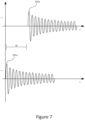
- Figure 7 shows the response signals as received from the first induction coil 200a and second induction coil 200b in response to the detection signals 500a, 500b in accordance with the scenario of Figure 5a (separate cooking vessels 400).
- Figure 8 shows the response signals as received from the first induction coil 200a and the second induction coil 200b in response to the detection signals 500a, 500b in accordance with the scenario of Figure 5b (single cooking vessel 400).
- the first response signal 501a and second response signal 501b are damped sinusoids as before.
- This indication 550 arises because the detection signal 500b provided to the second induction coil 200b acts on the same cooking vessel 400 (i.e. the same piece of material) and therefore changes the response signal 501a as observed at the first induction coil 200a.
- This indication may manifest as an additional increase in the amplitude of the response signal 501a. That is, the first response signal 501 is not a simple damped signal, but comprises an additional component corresponding to the second detection signal 500b. That is, the first response signal 501a shows an artefact of the second response signal 501b.
- the second detection signal 500b applied to the second induction coil 200b has had some effect at the first induction coil 200a. As mentioned above, this is only the case when the same cooking vessel occupies both induction coils 200a, 200b.
- the presence of such an indication 550 can be used to determine that the same cooking vessel 400 occupies both the first induction coil 200a and the second induction coil 200b (i.e. to distinguish between a single cooking vessel and separate cooking vessels).
- Figure 9 shows an example method performed by the controller 300.
- the controller 300 provides the first detection signal 500a to the first induction coil 200a. This causes the first induction coil 200a to generate a first response signal 501a.
- the controller 300 provides the second detection signal 500b to the second induction coil 200b. This causes the second induction coil 200b to generate a second response signal 501b.
- the controller 300 measures the first response signal 501a from the first induction coil 200a.
- the controller 300 identifies whether there is an indication 550 of the second detection signal in the first response signal 501a.
- the controller proceeds to S905, where it is determined that it is not the case that the same cooking vessel 400 occupies both the first induction coil 200a and second induction coil 200b.
- the controller 300 may additionally measure the second response signal 501b and only perform the identifying at S903 if both the first response signal 501a and second response signal 501b are damped. This is advantageous because if one (or both) of the response signals 501a, 501b are not damped, then there is no cooking vessel 400 present on the respective induction coil(s) and therefore the controller 300 can rule out the possibility that a single cooking vessel 400 occupies both induction coils 200a, 200b without needing to identify presence or absence of the indication 550 as described above.
- the controller 300 may provide a respective detection signal 500 and measure a respective response signal 501 from any induction coils 200 present. Any induction coils 200 that provide a damped response signal 501 can be determined to by occupied by (part of) a cooking vessel 400.
- the controller 300 can additionally analyse the response signal(s) 501 to identify which induction coil(s) 200 interfere with which other induction coil(s) 200 and use this to determine the location of the cooking vessel(s) 400 on the cooking surface, as described above.
- the controller 300 can identify a border between two adjacent cooking vessels 400 if two adjacent induction coils 200 provide damped response signals 501 but there is no indication 550 of another response signal 501 being present in either response signal 501.
- a real-world induction cooker 100 may comprise many induction coils 200 rather than the two in the simplified example described above. In such cases, there is the possibility of ambiguity between precisely which two (or more) induction coils 200 a single cooking vessel 400 is occupying.
- the controller 300 can also identify which adjacent induction coil 400 this is by leveraging a property (such as the time delay) of the detection signals 500 provided to each induction coil 400.
- the controller 300 may provide a respective detection signal 500 to each induction coil 200 with a different time delay.
- the controller 300 when the controller 300 measures the response signal from the first induction coil 200a, it can determine the delay between the start of the response signal and the indication 550. If the delay is around 10ms, then the controller 300 determines that the cooking vessel 400 occupying the first induction coil 200a is also occupying the second induction coil 200b. If instead the delay is around 20ms, then the controller 300 determines that the cooking vessel 400 occupying the first induction coil 200a is also occupying the third induction coil 200c. If there are two indications, at 10ms and 20ms respectively, then then the controller 300 determines that the cooking vessel 400 occupying the first induction coil 200a is also occupying both the second induction coil 200b and the third induction coil 200c.
- Figure 10 shows an example for a regular rectangular array of induction coils 200.
- nine different time delays can be used while still achieving the condition that no two adjacent coils have the same time delay. That is, the induction coils 200 can be grouped into nine sets, the induction coils 200 within each set having the same time delay.
- the time delays are labelled simply 1-9. It is appreciated that the actual time delays may be any time delay that can be accurately resolved by the controller 300. For example, the time delays may be 0ms, 10ms, 20ms, ..., 80ms. This can then repeat, meaning that the controller 300 can perform the cooking vessel layout determination in less than a second for an induction cooker 100 of any size.
- Figure 12 shows an example for a regular hexagonal array of induction coils 200. In this case, seven different time delays can be used while still achieving the condition that no two adjacent coils have the same time delay.
- the detection signals provided to each inductive coil 200 may be "different" or otherwise distinguishable.
- any property of the detection signal which is detectable in the response from an adjacent induction coil 200 when the same cooking vessel 400 is present may be used.
- the detection signals may have different frequencies, and/or may be modulated in some manner (e.g. amplitude modulation, frequency modulation, pulse width modulation), e.g. to embed a different code into each detection signal 500.
- the first response signal 501a is modulated by the second response signal 501b (if the cooking vessel 400 is over both induction coils 200, and not otherwise). That is, the first response signal 501a shows an artefact of the second response signal 501b.
- the numbers 1-9 may represent detection signals 500 having different frequencies.
- the detection signals 500 do not need to be delayed relative to one another. Rather, they can all be applied by the controller 300 at the same time (though in some examples detection signals 500 having different frequencies may be applied at different times, which may assist further in resolving the detected response signals 501).
- the controller 300 may apply a variety of techniques to identify an indication 550 in a given response signal 501 and, in particular, to identify which other induction coil 200 was the cause of the indication 550.
- the controller 300 may identify a beat frequency in the response signal 501 and then determine that the cooking vessel 400 overlaps with the other induction coil 200 which was provided with the detection signal 500 having the specific frequency required to produce that beat frequency.
- the controller 300 may apply a Fourier transform (e.g. an FFT) to identify the frequency components of the response signal 501.
- the controller 300 can then assign a single control zone for all the induction coils 200 which were provided with those frequencies, as a single cooking vessel 200 must be occupying all those induction coils 200.
- processor or processing system or circuitry referred to herein may in practice be provided by a single chip or integrated circuit or plural chips or integrated circuits, optionally provided as a chipset, an application-specific integrated circuit (ASIC), field-programmable gate array (FPGA), digital signal processor (DSP), graphics processing units (GPUs), etc.
- the chip or chips may comprise circuitry (as well as possibly firmware) for embodying at least one or more of a data processor or processors, a digital signal processor or processors, baseband circuitry and radio frequency circuitry, which are configurable so as to operate in accordance with the exemplary embodiments.
- the exemplary embodiments may be implemented at least in part by computer software stored in (non-transitory) memory and executable by the processor, or by hardware, or by a combination of tangibly stored software and hardware (and tangibly stored firmware).
- the invention also extends to computer programs, particularly computer programs on or in a carrier, adapted for putting the invention into practice.
- the program may be in the form of non-transitory source code, object code, a code intermediate source and object code such as in partially compiled form, or in any other non-transitory form suitable for use in the implementation of processes according to the invention.
- the carrier may be any entity or device capable of carrying the program.
- the carrier may comprise a storage medium, such as a solid-state drive (SSD) or other semiconductor-based RAM; a ROM, for example a CD ROM or a semiconductor ROM; a magnetic recording medium, for example a floppy disk or hard disk; optical memory devices in general; etc.
- SSD solid-state drive
- ROM read-only memory
- magnetic recording medium for example a floppy disk or hard disk
- optical memory devices in general etc.
Landscapes
- Physics & Mathematics (AREA)
- Electromagnetism (AREA)
- Induction Heating Cooking Devices (AREA)
Claims (15)
- Procédé de commande d'un appareil de cuisson à induction (100) comprenant au moins deux bobines d'induction (200) servant à chauffer par induction des récipients de cuisson (400), le procédé consistant à :fournir un signal de détection (500a) à une première desdites bobines d'induction (200a)fournir un signal de détection (500b) à une deuxième desdites bobines d'induction (200b) ; etmesurer un signal de réponse (501a) provenant de la première bobine d'induction (200a), etcaractérisé en ce que le procédé consiste à :
identifier que le signal de réponse (501a) provenant de la première bobine d'induction (200a) inclut une indication (550) d'un signal de réponse (501b) généré au niveau de la deuxième bobine d'induction (200b) en réponse au signal de détection (500b) fourni à la deuxième bobine d'induction (200b), déterminant ainsi qu'un même récipient de cuisson (400) occupe à la fois la première bobine d'induction (200a) et la deuxième bobine d'induction (200b). - Procédé selon la revendication 1, dans lequel le signal de détection (500b) fourni à la deuxième bobine d'induction (200b) est fourni à un moment ultérieur à celui auquel le signal de détection (500a) est fourni à la première bobine d'induction (200a), et l'indication (550) du signal de réponse (501b) généré au niveau de la deuxième bobine d'induction (200b) est une augmentation de l'amplitude du signal de réponse (501a) provenant de la première bobine d'induction (200a) à un instant correspondant au moment auquel le signal de détection (500b) a été fourni à la deuxième bobine d'induction (200b).
- Procédé selon la revendication 1 ou 2, dans lequel le signal de détection (500b) fourni à la deuxième bobine d'induction (200b) a une fréquence différente de celle du signal de détection (500a) fourni à la première bobine d'induction (200a), et dans lequel l'indication (550) du signal de réponse (501b) généré au niveau de la deuxième bobine d'induction (200b) est une somme du signal de réponse (501a) provenant de la première bobine d'induction (200a) et du signal de réponse (501b) provenant de la deuxième bobine d'induction (200b).
- Procédé selon l'une quelconque des revendications 1 à 3, consistant à mesurer le signal de réponse (501b) provenant de la deuxième bobine d'induction (200b), et dans lequel ladite identification est effectuée en réponse aux deux signaux de réponse (501a, 501b) étant amortis.
- Procédé selon l'une quelconque des revendications 1 à 4, consistant, en réponse à la détermination selon laquelle un même récipient de cuisson (400) occupe à la fois les première et deuxième bobines d'induction (200a, 200b), à attribuer les première et deuxième bobines d'induction (200a, 200b) à la même zone de commande de sorte que les première et deuxième bobines d'induction (200a, 200b) sont contrôlées par un unique réglage de commande.
- Procédé selon l'une quelconque des revendications 1 à 5, consistant à :mesurer le signal de réponse (501b) provenant de la deuxième bobine d'induction (200b)identifier que les deux signaux de réponse (501a, 501b) sont amortis mais qu'il n'y a aucune indication (550) d'un signal de réponse (501b) généré au niveau de la deuxième bobine d'induction (200b) en réponse au deuxième signal de détection (500b), déterminant ainsi que deux récipients de cuisson séparés occupent respectivement les première et deuxième bobines d'induction (200a, 200b) ; eten réponse à la détermination selon laquelle deux récipients séparés occupent respectivement les première et deuxième bobines d'induction (200a, 200b), attribuer à chacune des première et deuxième bobines d'induction (200a, 200b) des zones de commande séparées de sorte que les première et deuxième bobines d'induction (200a, 200b) sont commandées par différents réglages de commande respectifs.
- Procédé selon l'une quelconque des revendications 1 à 6, dans lequel l'appareil de cuisson à induction (100) comprend au moins trois bobines d'induction (200a, 200b, 200c), le procédé consistant à :fournir un signal de détection à une troisième desdites bobines d'induction (200c) afin d'amener la troisième bobine d'induction (200c) à générer un signal de réponse ; etidentifier que le signal de réponse provenant de la première bobine d'induction (200a) inclut une indication (550) d'un signal de réponse généré au niveau de la troisième bobine d'induction (200c) en réponse au signal de détection fourni à la troisième bobine d'induction (200c), déterminant ainsi qu'un même récipient de cuisson (400) occupe à la fois la première bobine d'induction (200a) et la troisième bobine d'induction (200c).
- Procédé selon la revendication 7, dans lequel le signal de détection fourni à la troisième bobine d'induction (200c) est fourni à un moment ultérieur à celui auquel les signaux de détection (500a, 500b) sont fournis aux première et deuxième bobines d'induction (200a, 200b), et l'indication (550) du signal de réponse généré au niveau de la troisième bobine d'induction (200c) est une augmentation de l'amplitude du signal de réponse (501a) provenant de la première bobine d'induction (200a) à un instant correspondant au moment auquel le signal de détection a été fourni à la troisième bobine d'induction (200c).
- Contrôleur (300) destiné à un appareil de cuisson à induction (100), comprenant au moins deux bobines d'induction (200) servant à chauffer par induction des récipients de cuisson (400), le contrôleur (300) étant configuré, une fois installé sur l'appareil de cuisson à induction (100), pour :fournir un signal de détection (500a) à une première desdites bobines d'induction (200a)fournir un signal de détection (500b) à une deuxième desdites bobines d'induction (200b)mesurer un signal de réponse (501a) provenant de la première bobine d'induction (200a), etcaractérisé en ce qu'il est en outre configuré pour :
identifier si le signal de réponse (501a) provenant de la première bobine d'induction (200a) inclut une indication (550) d'un signal de réponse (501b) généré au niveau de la deuxième bobine d'induction (200b) en réponse au deuxième signal de détection (500b), déterminant ainsi qu'un même récipient de cuisson (400) occupe à la fois la première bobine d'induction (200a) et la deuxième bobine d'induction (200b). - Contrôleur (300) selon la revendication 9, configuré pour fournir le signal de détection (500b) à la deuxième bobine d'induction (200b) à un moment ultérieur à celui auquel le signal de détection (500a) est fourni à la première bobine d'induction (200a), dans lequel l'indication (550) du signal de réponse (501b) généré au niveau de la deuxième bobine d'induction (200b) est une augmentation de l'amplitude du signal de réponse (501a) provenant de la première bobine d'induction (200a) à un instant correspondant au moment auquel le signal de détection (500b) a été fourni à la deuxième bobine d'induction (200b).
- Contrôleur (300) selon la revendication 9 ou 10, dans lequel le signal de détection (500b) fourni à la deuxième bobine d'induction (200b) a une fréquence différente de celle du signal de détection (500a) fourni à la première bobine d'induction (200a), et dans lequel l'indication (550) du signal de réponse (501b) généré au niveau de la deuxième bobine d'induction (200b) est une somme du signal de réponse (501a) provenant de la première bobine d'induction (200a) et du signal de réponse (501b) provenant de la deuxième bobine d'induction (200b).
- Contrôleur (300) selon l'une quelconque des revendications 9 à 11, configuré pour mesurer le signal de réponse (501b) provenant de la deuxième bobine d'induction (200b), et dans lequel le contrôleur (300) est configuré pour effectuer ladite identification en réponse aux deux signaux de réponse (501a, 501b) étant amortis.
- Contrôleur (300) selon l'une quelconque des revendications 9 à 12, configuré, en réponse à la détermination selon laquelle un même récipient de cuisson (400) occupe à la fois les première et deuxième bobines d'induction (200a, 200b), pour attribuer les première et deuxième bobines d'induction (200a, 200b) à la même zone de commande de sorte que les première et deuxième bobines d'induction (200a, 200b) sont commandées par un unique réglage de commande.
- Contrôleur (300) selon l'une quelconque des revendications 9 à 13, dans lequel l'appareil de cuisson à induction (100) comprend au moins trois bobines d'induction (200a, 200b, 200c), et le contrôleur (300) est configuré pour :fournir un signal de détection à une troisième desdites bobines d'induction (200c) pour amener la troisième bobine d'induction (200c) à générer un signal de réponse ; etidentifier que le signal de réponse provenant de la première bobine d'induction (200a) inclut une indication (550) d'un signal de réponse généré au niveau de la troisième bobine d'induction (200c) en réponse au signal de détection fourni à la troisième bobine d'induction (200c), déterminant ainsi qu'un même récipient de cuisson (400) occupe à la fois la première bobine d'induction (200a) et la troisième bobine d'induction (200c).
- Appareil de cuisson à induction (100), comprenant le contrôleur (300) selon l'une quelconque des revendications 9 à 14 et de multiples bobines d'induction (200).
Applications Claiming Priority (1)
| Application Number | Priority Date | Filing Date | Title |
|---|---|---|---|
| PCT/EP2020/074357 WO2022048732A1 (fr) | 2020-09-01 | 2020-09-01 | Procédé de dispositif de cuisson par induction sans zone et dispositif de commande |
Publications (2)
| Publication Number | Publication Date |
|---|---|
| EP4218363A1 EP4218363A1 (fr) | 2023-08-02 |
| EP4218363B1 true EP4218363B1 (fr) | 2024-09-25 |
Family
ID=72322469
Family Applications (1)
| Application Number | Title | Priority Date | Filing Date |
|---|---|---|---|
| EP20765008.6A Active EP4218363B1 (fr) | 2020-09-01 | 2020-09-01 | Procédé de dispositif de cuisson par induction sans zone et dispositif de commande |
Country Status (6)
| Country | Link |
|---|---|
| US (1) | US20230292409A1 (fr) |
| EP (1) | EP4218363B1 (fr) |
| JP (1) | JP2023539530A (fr) |
| KR (1) | KR20230062839A (fr) |
| CN (1) | CN116018879A (fr) |
| WO (1) | WO2022048732A1 (fr) |
Families Citing this family (1)
| Publication number | Priority date | Publication date | Assignee | Title |
|---|---|---|---|---|
| US12464607B2 (en) * | 2020-02-07 | 2025-11-04 | BSH Hausgeräte GmbH | Cooking device |
Citations (1)
| Publication number | Priority date | Publication date | Assignee | Title |
|---|---|---|---|---|
| EP2779787B1 (fr) * | 2013-03-11 | 2015-06-17 | Electrolux Appliances Aktiebolag | Procédé de détection d'un ustensile de cuisson sur une plaque à induction, plaque à induction et appareil de cuisson |
Family Cites Families (4)
| Publication number | Priority date | Publication date | Assignee | Title |
|---|---|---|---|---|
| KR101835714B1 (ko) * | 2011-04-01 | 2018-03-08 | 삼성전자주식회사 | 유도가열조리기 및 그 제어방법 |
| WO2016181208A1 (fr) * | 2015-05-08 | 2016-11-17 | Waco Pacific Ltd. | Appareil de cuisson par induction et procédé de commande d'un appareil de cuisson par induction |
| JP6793028B2 (ja) * | 2016-12-19 | 2020-12-02 | リンナイ株式会社 | 加熱調理器 |
| KR102329134B1 (ko) * | 2017-04-28 | 2021-11-19 | 삼성전자주식회사 | 조리 장치 및 그 제어 방법 |
-
2020
- 2020-09-01 US US18/024,238 patent/US20230292409A1/en not_active Abandoned
- 2020-09-01 KR KR1020237010254A patent/KR20230062839A/ko not_active Withdrawn
- 2020-09-01 WO PCT/EP2020/074357 patent/WO2022048732A1/fr not_active Ceased
- 2020-09-01 JP JP2023514449A patent/JP2023539530A/ja not_active Withdrawn
- 2020-09-01 CN CN202080103672.9A patent/CN116018879A/zh active Pending
- 2020-09-01 EP EP20765008.6A patent/EP4218363B1/fr active Active
Patent Citations (1)
| Publication number | Priority date | Publication date | Assignee | Title |
|---|---|---|---|---|
| EP2779787B1 (fr) * | 2013-03-11 | 2015-06-17 | Electrolux Appliances Aktiebolag | Procédé de détection d'un ustensile de cuisson sur une plaque à induction, plaque à induction et appareil de cuisson |
Also Published As
| Publication number | Publication date |
|---|---|
| EP4218363A1 (fr) | 2023-08-02 |
| KR20230062839A (ko) | 2023-05-09 |
| WO2022048732A1 (fr) | 2022-03-10 |
| US20230292409A1 (en) | 2023-09-14 |
| JP2023539530A (ja) | 2023-09-14 |
| CN116018879A (zh) | 2023-04-25 |
Similar Documents
| Publication | Publication Date | Title |
|---|---|---|
| EP3195694B1 (fr) | Plaque de cuisson à induction avec détection d'ébullition et commande de l'énergie par induction, procédé pour chauffer des aliments avec une plaque de cuisson à induction et programme informatique | |
| AU2014231190B2 (en) | Method of detecting cookware on an induction hob, induction hob and cooking appliance | |
| CN103493587B (zh) | 带有锅检测装置的电磁炉铁架以及用于操作电磁炉铁架的方法 | |
| KR102260903B1 (ko) | 풀 프리존 인덕션 레인지 | |
| CN104303593B (zh) | 具有多个感应线圈的感应烹饪灶台 | |
| EP4218363B1 (fr) | Procédé de dispositif de cuisson par induction sans zone et dispositif de commande | |
| US10448461B2 (en) | Cooktop having a plurality of heating elements | |
| JP4839786B2 (ja) | 誘導加熱装置 | |
| US20120125918A1 (en) | Hotplate having at least two heating zones | |
| US6583392B2 (en) | Apparatus and method for determining properties of a cooktop using ultrasound techniques | |
| US8492684B2 (en) | Method for detecting the presence of a cooking vessel on an induction cooking hob and hob using such method | |
| CN109699098A (zh) | 电磁加热烹饪器具及其锅具偏移检测方法和装置 | |
| US20130175259A1 (en) | Induction cooking electromagnetic induced rejection methods | |
| US12010781B2 (en) | Induction cooker | |
| TR202013792A2 (tr) | Bölgesi̇z i̇ndüksi̇yonlu pi̇şi̇ri̇ci̇ yöntemi̇ ve kontrolör | |
| WO2020152499A1 (fr) | Dispositif de détection de caractéristiques de récipient de cuisson et procédé de détection de caractéristiques de récipient de cuisson | |
| JP4933989B2 (ja) | 誘導加熱調理器 | |
| EP3462812A1 (fr) | Procédé de fonctionnement d'un appareil de cuisson, cuisinière, dispositif de commande pour un appareil de cuisson et programme informatique | |
| KR102213164B1 (ko) | 화구 주변의 물체를 감지하는 가열 장치 | |
| JP5240321B2 (ja) | 誘導加熱装置 | |
| CN109548210A (zh) | 一种测温精度高的线圈盘结构 | |
| JP5301045B2 (ja) | 誘導加熱調理器 | |
| CA2722434A1 (fr) | Unite d'entree | |
| EP3503672A1 (fr) | Plaque de cuisson à induction | |
| TR201706344A2 (tr) | İndüksi̇yonlu pi̇şi̇rme ci̇hazi ve yöntem |
Legal Events
| Date | Code | Title | Description |
|---|---|---|---|
| STAA | Information on the status of an ep patent application or granted ep patent |
Free format text: STATUS: UNKNOWN |
|
| STAA | Information on the status of an ep patent application or granted ep patent |
Free format text: STATUS: THE INTERNATIONAL PUBLICATION HAS BEEN MADE |
|
| PUAI | Public reference made under article 153(3) epc to a published international application that has entered the european phase |
Free format text: ORIGINAL CODE: 0009012 |
|
| STAA | Information on the status of an ep patent application or granted ep patent |
Free format text: STATUS: REQUEST FOR EXAMINATION WAS MADE |
|
| 17P | Request for examination filed |
Effective date: 20230620 |
|
| AK | Designated contracting states |
Kind code of ref document: A1 Designated state(s): AL AT BE BG CH CY CZ DE DK EE ES FI FR GB GR HR HU IE IS IT LI LT LU LV MC MK MT NL NO PL PT RO RS SE SI SK SM TR |
|
| DAV | Request for validation of the european patent (deleted) | ||
| DAX | Request for extension of the european patent (deleted) | ||
| GRAP | Despatch of communication of intention to grant a patent |
Free format text: ORIGINAL CODE: EPIDOSNIGR1 |
|
| STAA | Information on the status of an ep patent application or granted ep patent |
Free format text: STATUS: GRANT OF PATENT IS INTENDED |
|
| INTG | Intention to grant announced |
Effective date: 20240516 |
|
| GRAS | Grant fee paid |
Free format text: ORIGINAL CODE: EPIDOSNIGR3 |
|
| GRAA | (expected) grant |
Free format text: ORIGINAL CODE: 0009210 |
|
| STAA | Information on the status of an ep patent application or granted ep patent |
Free format text: STATUS: THE PATENT HAS BEEN GRANTED |
|
| AK | Designated contracting states |
Kind code of ref document: B1 Designated state(s): AL AT BE BG CH CY CZ DE DK EE ES FI FR GB GR HR HU IE IS IT LI LT LU LV MC MK MT NL NO PL PT RO RS SE SI SK SM TR |
|
| REG | Reference to a national code |
Ref country code: GB Ref legal event code: FG4D |
|
| REG | Reference to a national code |
Ref country code: CH Ref legal event code: EP |
|
| REG | Reference to a national code |
Ref country code: DE Ref legal event code: R096 Ref document number: 602020038348 Country of ref document: DE |
|
| REG | Reference to a national code |
Ref country code: IE Ref legal event code: FG4D |
|
| REG | Reference to a national code |
Ref country code: LT Ref legal event code: MG9D |
|
| PG25 | Lapsed in a contracting state [announced via postgrant information from national office to epo] |
Ref country code: NO Free format text: LAPSE BECAUSE OF FAILURE TO SUBMIT A TRANSLATION OF THE DESCRIPTION OR TO PAY THE FEE WITHIN THE PRESCRIBED TIME-LIMIT Effective date: 20241225 |
|
| PG25 | Lapsed in a contracting state [announced via postgrant information from national office to epo] |
Ref country code: GR Free format text: LAPSE BECAUSE OF FAILURE TO SUBMIT A TRANSLATION OF THE DESCRIPTION OR TO PAY THE FEE WITHIN THE PRESCRIBED TIME-LIMIT Effective date: 20241226 Ref country code: FI Free format text: LAPSE BECAUSE OF FAILURE TO SUBMIT A TRANSLATION OF THE DESCRIPTION OR TO PAY THE FEE WITHIN THE PRESCRIBED TIME-LIMIT Effective date: 20240925 |
|
| PG25 | Lapsed in a contracting state [announced via postgrant information from national office to epo] |
Ref country code: BG Free format text: LAPSE BECAUSE OF FAILURE TO SUBMIT A TRANSLATION OF THE DESCRIPTION OR TO PAY THE FEE WITHIN THE PRESCRIBED TIME-LIMIT Effective date: 20240925 |
|
| PG25 | Lapsed in a contracting state [announced via postgrant information from national office to epo] |
Ref country code: LV Free format text: LAPSE BECAUSE OF FAILURE TO SUBMIT A TRANSLATION OF THE DESCRIPTION OR TO PAY THE FEE WITHIN THE PRESCRIBED TIME-LIMIT Effective date: 20240925 |
|
| PG25 | Lapsed in a contracting state [announced via postgrant information from national office to epo] |
Ref country code: RS Free format text: LAPSE BECAUSE OF FAILURE TO SUBMIT A TRANSLATION OF THE DESCRIPTION OR TO PAY THE FEE WITHIN THE PRESCRIBED TIME-LIMIT Effective date: 20241225 |
|
| REG | Reference to a national code |
Ref country code: NL Ref legal event code: MP Effective date: 20240925 |
|
| PG25 | Lapsed in a contracting state [announced via postgrant information from national office to epo] |
Ref country code: RS Free format text: LAPSE BECAUSE OF FAILURE TO SUBMIT A TRANSLATION OF THE DESCRIPTION OR TO PAY THE FEE WITHIN THE PRESCRIBED TIME-LIMIT Effective date: 20241225 Ref country code: NO Free format text: LAPSE BECAUSE OF FAILURE TO SUBMIT A TRANSLATION OF THE DESCRIPTION OR TO PAY THE FEE WITHIN THE PRESCRIBED TIME-LIMIT Effective date: 20241225 Ref country code: LV Free format text: LAPSE BECAUSE OF FAILURE TO SUBMIT A TRANSLATION OF THE DESCRIPTION OR TO PAY THE FEE WITHIN THE PRESCRIBED TIME-LIMIT Effective date: 20240925 Ref country code: GR Free format text: LAPSE BECAUSE OF FAILURE TO SUBMIT A TRANSLATION OF THE DESCRIPTION OR TO PAY THE FEE WITHIN THE PRESCRIBED TIME-LIMIT Effective date: 20241226 Ref country code: FI Free format text: LAPSE BECAUSE OF FAILURE TO SUBMIT A TRANSLATION OF THE DESCRIPTION OR TO PAY THE FEE WITHIN THE PRESCRIBED TIME-LIMIT Effective date: 20240925 Ref country code: BG Free format text: LAPSE BECAUSE OF FAILURE TO SUBMIT A TRANSLATION OF THE DESCRIPTION OR TO PAY THE FEE WITHIN THE PRESCRIBED TIME-LIMIT Effective date: 20240925 |
|
| REG | Reference to a national code |
Ref country code: AT Ref legal event code: MK05 Ref document number: 1727742 Country of ref document: AT Kind code of ref document: T Effective date: 20240925 |
|
| PG25 | Lapsed in a contracting state [announced via postgrant information from national office to epo] |
Ref country code: NL Free format text: LAPSE BECAUSE OF FAILURE TO SUBMIT A TRANSLATION OF THE DESCRIPTION OR TO PAY THE FEE WITHIN THE PRESCRIBED TIME-LIMIT Effective date: 20240925 |
|
| PG25 | Lapsed in a contracting state [announced via postgrant information from national office to epo] |
Ref country code: PT Free format text: LAPSE BECAUSE OF FAILURE TO SUBMIT A TRANSLATION OF THE DESCRIPTION OR TO PAY THE FEE WITHIN THE PRESCRIBED TIME-LIMIT Effective date: 20250127 Ref country code: IS Free format text: LAPSE BECAUSE OF FAILURE TO SUBMIT A TRANSLATION OF THE DESCRIPTION OR TO PAY THE FEE WITHIN THE PRESCRIBED TIME-LIMIT Effective date: 20250125 |
|
| PG25 | Lapsed in a contracting state [announced via postgrant information from national office to epo] |
Ref country code: RO Free format text: LAPSE BECAUSE OF FAILURE TO SUBMIT A TRANSLATION OF THE DESCRIPTION OR TO PAY THE FEE WITHIN THE PRESCRIBED TIME-LIMIT Effective date: 20240925 Ref country code: SM Free format text: LAPSE BECAUSE OF FAILURE TO SUBMIT A TRANSLATION OF THE DESCRIPTION OR TO PAY THE FEE WITHIN THE PRESCRIBED TIME-LIMIT Effective date: 20240925 |
|
| PG25 | Lapsed in a contracting state [announced via postgrant information from national office to epo] |
Ref country code: ES Free format text: LAPSE BECAUSE OF FAILURE TO SUBMIT A TRANSLATION OF THE DESCRIPTION OR TO PAY THE FEE WITHIN THE PRESCRIBED TIME-LIMIT Effective date: 20240925 |
|
| PG25 | Lapsed in a contracting state [announced via postgrant information from national office to epo] |
Ref country code: EE Free format text: LAPSE BECAUSE OF FAILURE TO SUBMIT A TRANSLATION OF THE DESCRIPTION OR TO PAY THE FEE WITHIN THE PRESCRIBED TIME-LIMIT Effective date: 20240925 Ref country code: AT Free format text: LAPSE BECAUSE OF FAILURE TO SUBMIT A TRANSLATION OF THE DESCRIPTION OR TO PAY THE FEE WITHIN THE PRESCRIBED TIME-LIMIT Effective date: 20240925 |
|
| PG25 | Lapsed in a contracting state [announced via postgrant information from national office to epo] |
Ref country code: PL Free format text: LAPSE BECAUSE OF FAILURE TO SUBMIT A TRANSLATION OF THE DESCRIPTION OR TO PAY THE FEE WITHIN THE PRESCRIBED TIME-LIMIT Effective date: 20240925 Ref country code: CZ Free format text: LAPSE BECAUSE OF FAILURE TO SUBMIT A TRANSLATION OF THE DESCRIPTION OR TO PAY THE FEE WITHIN THE PRESCRIBED TIME-LIMIT Effective date: 20240925 |
|
| PG25 | Lapsed in a contracting state [announced via postgrant information from national office to epo] |
Ref country code: SK Free format text: LAPSE BECAUSE OF FAILURE TO SUBMIT A TRANSLATION OF THE DESCRIPTION OR TO PAY THE FEE WITHIN THE PRESCRIBED TIME-LIMIT Effective date: 20240925 Ref country code: IT Free format text: LAPSE BECAUSE OF FAILURE TO SUBMIT A TRANSLATION OF THE DESCRIPTION OR TO PAY THE FEE WITHIN THE PRESCRIBED TIME-LIMIT Effective date: 20240925 |
|
| REG | Reference to a national code |
Ref country code: DE Ref legal event code: R097 Ref document number: 602020038348 Country of ref document: DE |
|
| PG25 | Lapsed in a contracting state [announced via postgrant information from national office to epo] |
Ref country code: DK Free format text: LAPSE BECAUSE OF FAILURE TO SUBMIT A TRANSLATION OF THE DESCRIPTION OR TO PAY THE FEE WITHIN THE PRESCRIBED TIME-LIMIT Effective date: 20240925 |
|
| PLBE | No opposition filed within time limit |
Free format text: ORIGINAL CODE: 0009261 |
|
| STAA | Information on the status of an ep patent application or granted ep patent |
Free format text: STATUS: NO OPPOSITION FILED WITHIN TIME LIMIT |
|
| 26N | No opposition filed |
Effective date: 20250626 |
|
| PG25 | Lapsed in a contracting state [announced via postgrant information from national office to epo] |
Ref country code: SE Free format text: LAPSE BECAUSE OF FAILURE TO SUBMIT A TRANSLATION OF THE DESCRIPTION OR TO PAY THE FEE WITHIN THE PRESCRIBED TIME-LIMIT Effective date: 20240925 |
|
| PGFP | Annual fee paid to national office [announced via postgrant information from national office to epo] |
Ref country code: DE Payment date: 20250806 Year of fee payment: 6 |
|
| PGFP | Annual fee paid to national office [announced via postgrant information from national office to epo] |
Ref country code: TR Payment date: 20250826 Year of fee payment: 6 |
|
| REG | Reference to a national code |
Ref country code: DE Ref legal event code: R082 Ref document number: 602020038348 Country of ref document: DE Representative=s name: WESTPHAL, MUSSGNUG & PARTNER PATENTANWAELTE MI, DE |
|
| PG25 | Lapsed in a contracting state [announced via postgrant information from national office to epo] |
Ref country code: HR Free format text: LAPSE BECAUSE OF FAILURE TO SUBMIT A TRANSLATION OF THE DESCRIPTION OR TO PAY THE FEE WITHIN THE PRESCRIBED TIME-LIMIT Effective date: 20240925 |