EP4218558A1 - Système et procédé de surveillance de la fréquence respiratoire et de la saturation en oxygène - Google Patents
Système et procédé de surveillance de la fréquence respiratoire et de la saturation en oxygène Download PDFInfo
- Publication number
- EP4218558A1 EP4218558A1 EP23162749.8A EP23162749A EP4218558A1 EP 4218558 A1 EP4218558 A1 EP 4218558A1 EP 23162749 A EP23162749 A EP 23162749A EP 4218558 A1 EP4218558 A1 EP 4218558A1
- Authority
- EP
- European Patent Office
- Prior art keywords
- patient
- wearable device
- wrist
- respiratory rate
- light
- Prior art date
- Legal status (The legal status is an assumption and is not a legal conclusion. Google has not performed a legal analysis and makes no representation as to the accuracy of the status listed.)
- Withdrawn
Links
Images




Classifications
-
- A—HUMAN NECESSITIES
- A61—MEDICAL OR VETERINARY SCIENCE; HYGIENE
- A61B—DIAGNOSIS; SURGERY; IDENTIFICATION
- A61B5/00—Measuring for diagnostic purposes; Identification of persons
- A61B5/68—Arrangements of detecting, measuring or recording means, e.g. sensors, in relation to patient
- A61B5/6801—Arrangements of detecting, measuring or recording means, e.g. sensors, in relation to patient specially adapted to be attached to or worn on the body surface
- A61B5/6802—Sensor mounted on worn items
- A61B5/681—Wristwatch-type devices
-
- A—HUMAN NECESSITIES
- A61—MEDICAL OR VETERINARY SCIENCE; HYGIENE
- A61B—DIAGNOSIS; SURGERY; IDENTIFICATION
- A61B5/00—Measuring for diagnostic purposes; Identification of persons
- A61B5/02—Detecting, measuring or recording for evaluating the cardiovascular system, e.g. pulse, heart rate, blood pressure or blood flow
- A61B5/0205—Simultaneously evaluating both cardiovascular conditions and different types of body conditions, e.g. heart and respiratory condition
-
- A—HUMAN NECESSITIES
- A61—MEDICAL OR VETERINARY SCIENCE; HYGIENE
- A61B—DIAGNOSIS; SURGERY; IDENTIFICATION
- A61B5/00—Measuring for diagnostic purposes; Identification of persons
- A61B5/08—Measuring devices for evaluating the respiratory organs
- A61B5/0816—Measuring devices for examining respiratory frequency
-
- A—HUMAN NECESSITIES
- A61—MEDICAL OR VETERINARY SCIENCE; HYGIENE
- A61B—DIAGNOSIS; SURGERY; IDENTIFICATION
- A61B5/00—Measuring for diagnostic purposes; Identification of persons
- A61B5/145—Measuring characteristics of blood in vivo, e.g. gas concentration or pH-value ; Measuring characteristics of body fluids or tissues, e.g. interstitial fluid or cerebral tissue
- A61B5/1455—Measuring characteristics of blood in vivo, e.g. gas concentration or pH-value ; Measuring characteristics of body fluids or tissues, e.g. interstitial fluid or cerebral tissue using optical sensors, e.g. spectral photometrical oximeters
- A61B5/14551—Measuring characteristics of blood in vivo, e.g. gas concentration or pH-value ; Measuring characteristics of body fluids or tissues, e.g. interstitial fluid or cerebral tissue using optical sensors, e.g. spectral photometrical oximeters for measuring blood gases
-
- A—HUMAN NECESSITIES
- A61—MEDICAL OR VETERINARY SCIENCE; HYGIENE
- A61B—DIAGNOSIS; SURGERY; IDENTIFICATION
- A61B5/00—Measuring for diagnostic purposes; Identification of persons
- A61B5/24—Detecting, measuring or recording bioelectric or biomagnetic signals of the body or parts thereof
- A61B5/316—Modalities, i.e. specific diagnostic methods
- A61B5/318—Heart-related electrical modalities, e.g. electrocardiography [ECG]
-
- A—HUMAN NECESSITIES
- A61—MEDICAL OR VETERINARY SCIENCE; HYGIENE
- A61B—DIAGNOSIS; SURGERY; IDENTIFICATION
- A61B5/00—Measuring for diagnostic purposes; Identification of persons
- A61B5/48—Other medical applications
- A61B5/4842—Monitoring progression or stage of a disease
-
- A—HUMAN NECESSITIES
- A61—MEDICAL OR VETERINARY SCIENCE; HYGIENE
- A61B—DIAGNOSIS; SURGERY; IDENTIFICATION
- A61B5/00—Measuring for diagnostic purposes; Identification of persons
- A61B5/72—Signal processing specially adapted for physiological signals or for diagnostic purposes
- A61B5/7235—Details of waveform analysis
-
- A—HUMAN NECESSITIES
- A61—MEDICAL OR VETERINARY SCIENCE; HYGIENE
- A61B—DIAGNOSIS; SURGERY; IDENTIFICATION
- A61B5/00—Measuring for diagnostic purposes; Identification of persons
- A61B5/72—Signal processing specially adapted for physiological signals or for diagnostic purposes
- A61B5/7271—Specific aspects of physiological measurement analysis
- A61B5/7275—Determining trends in physiological measurement data; Predicting development of a medical condition based on physiological measurements, e.g. determining a risk factor
-
- G—PHYSICS
- G16—INFORMATION AND COMMUNICATION TECHNOLOGY [ICT] SPECIALLY ADAPTED FOR SPECIFIC APPLICATION FIELDS
- G16H—HEALTHCARE INFORMATICS, i.e. INFORMATION AND COMMUNICATION TECHNOLOGY [ICT] SPECIALLY ADAPTED FOR THE HANDLING OR PROCESSING OF MEDICAL OR HEALTHCARE DATA
- G16H40/00—ICT specially adapted for the management or administration of healthcare resources or facilities; ICT specially adapted for the management or operation of medical equipment or devices
- G16H40/60—ICT specially adapted for the management or administration of healthcare resources or facilities; ICT specially adapted for the management or operation of medical equipment or devices for the operation of medical equipment or devices
- G16H40/67—ICT specially adapted for the management or administration of healthcare resources or facilities; ICT specially adapted for the management or operation of medical equipment or devices for the operation of medical equipment or devices for remote operation
-
- G—PHYSICS
- G16—INFORMATION AND COMMUNICATION TECHNOLOGY [ICT] SPECIALLY ADAPTED FOR SPECIFIC APPLICATION FIELDS
- G16H—HEALTHCARE INFORMATICS, i.e. INFORMATION AND COMMUNICATION TECHNOLOGY [ICT] SPECIALLY ADAPTED FOR THE HANDLING OR PROCESSING OF MEDICAL OR HEALTHCARE DATA
- G16H50/00—ICT specially adapted for medical diagnosis, medical simulation or medical data mining; ICT specially adapted for detecting, monitoring or modelling epidemics or pandemics
- G16H50/20—ICT specially adapted for medical diagnosis, medical simulation or medical data mining; ICT specially adapted for detecting, monitoring or modelling epidemics or pandemics for computer-aided diagnosis, e.g. based on medical expert systems
-
- A—HUMAN NECESSITIES
- A61—MEDICAL OR VETERINARY SCIENCE; HYGIENE
- A61B—DIAGNOSIS; SURGERY; IDENTIFICATION
- A61B2562/00—Details of sensors; Constructional details of sensor housings or probes; Accessories for sensors
- A61B2562/02—Details of sensors specially adapted for in-vivo measurements
- A61B2562/0219—Inertial sensors, e.g. accelerometers, gyroscopes, tilt switches
-
- A—HUMAN NECESSITIES
- A61—MEDICAL OR VETERINARY SCIENCE; HYGIENE
- A61B—DIAGNOSIS; SURGERY; IDENTIFICATION
- A61B5/00—Measuring for diagnostic purposes; Identification of persons
- A61B5/103—Measuring devices for testing the shape, pattern, colour, size or movement of the body or parts thereof, for diagnostic purposes
- A61B5/11—Measuring movement of the entire body or parts thereof, e.g. head or hand tremor or mobility of a limb
- A61B5/113—Measuring movement of the entire body or parts thereof, e.g. head or hand tremor or mobility of a limb occurring during breathing
Definitions
- U.S. Patent Application No. 14/983,118 is a Continuation-in-Part of U.S. Patent Application No. 14/738,666, titled “Monitoring Health Status of People Suffering from Chronic Diseases," filed on June 12, 2015 , a Continuation-in-Part of U.S. Patent application No. 14/738,636, titled “Wearable Device Electrocardiogram,” filed on June 12, 2015 , and a Continuation-in-Part of U.S. Patent Application No. 14/738,711, titled “Pulse Oximetry,” filed on June 12, 2015 . All of the disclosures of the aforementioned applications are incorporated herein by reference for all purposes, including all references cited therein.
- the present application relates to systems and methods for monitoring medical parameters of people, and more specifically to systems and methods for monitoring respiratory rate and oxygen saturation.
- Monitoring chronic diseases which includes measuring medical parameters, is central to providing appropriate and timely treatment to patients suffering from such chronic diseases as chronic heart failure, cardiac arrhythmia, chronic obstructive pulmonary disease, asthma, and diabetes.
- monitoring is carried out and measurements are taken while a patient is hospitalized or in other clinical settings. Appropriate treatment regimens can be based on these measurements, and thus it is highly beneficial to monitor medical parameters of the patient after the patient is released from the hospital. Therefore, the patient can be asked to visit the hospital or clinic periodically for monitoring and adjustment of treatment, if necessary.
- a system for monitoring a respiratory rate of a patient comprising a wearable device configured to be disposed around a wrist of the patient, the wearable device comprising first and second optical sensors each comprising a plurality of light transmitters and a plurality of light detectors.
- first and second optical sensors each comprising a plurality of light transmitters and a plurality of light detectors.
- the first optical sensor is located to cover skin area covering an artery of the wrist and the second optical sensor is located on a dorsal side of the wrist.
- the light transmitters of the first optical sensor are configured to transmit light towards the skin area and the artery of the wrist and the light detectors of the first optical sensor are configured to measure the light reflected from the skin area and the artery.
- the system comprises a processor communicatively connected to the first and second optical sensors.
- the processor is configured to determine intervals between subsequent heart beats of the patient based on the light reflected from the skin area and the artery measured by the light detectors.
- the processor is configured to obtain a sinus arrhythmia waveform based on the determined intervals between subsequent heart beats.
- the processor is configured to derive the respiratory rate of the patient from the obtained sinus arrhythmia waveform.
- a method for monitoring a respiratory rate of a patient comprising a system comprising a wearable device configured to be disposed around a wrist of the patient.
- the wearable device comprises first and second optical sensors each comprising a plurality of light transmitters and a plurality of light detectors.
- first optical sensor is located to cover skin area covering an artery of the wrist and the second optical sensor is located on a dorsal side of the wrist.
- the system comprises a processor communicatively connected to the first and second optical sensors.
- the method comprises transmitting, using the light transmitters of the first optical sensor, light towards the skin area and the artery of the wrist, and measuring, using the light detectors of the first optical sensor, the light reflected from the skin area and the artery.
- the method comprises determining intervals between subsequent heart beats of the patient based on the light reflected from the skin area and the artery measured by the light detectors.
- the method comprises obtaining a sinus arrhythmia waveform based on the determined intervals between subsequent heart beats.
- the method comprises deriving the respiratory rate of the patient from the obtained sinus arrhythmia waveform.
- Embodiments of the present disclosure can allow measuring medical parameters of a patient in a non-intrusive manner while, for example, the patient is at home, at work, outdoors, traveling, and at other stationary or mobile environments.
- Some example embodiments can provide for a wearable device (e.g., a wristband, a watch, or a bracelet) that includes sensors configured to measure medical parameters such as, for example, oxygen saturation, respiratory rate, and the like. The measurements can be taken during daytime and nighttime for days, weeks, months, and years.
- the medical parameters can be analyzed to determine trends in the medical parameters and to determine whether the severity of the patient's chronic disease (e.g., a heart disease, diabetes, lung disease, and so on) worsens or improves.
- Embodiments of the present technology may facilitate a rapid reaction to provide an appropriate and timely treatment for the patient.
- the early treatment may allow taking timely preventive measures to avoid worsening of the patient's condition to the point of requiring an emergency hospitalization and associated expensive medical treatment.
- a method for monitoring medical parameters of a patient can include measuring at a palmar surface of a wrist of the patient, by a first optical sensor of a wearable device configured to be disposed around the wrist of the patient, a first red wavelength PPG signal and a first infrared wavelength PPG signal.
- the method may include measuring from a dorsal surface of the wrist, by a second optical sensor, a second red wavelength PPG signal and a second infrared wavelength PPG signal.
- the method may also include determining, by a processor communicatively connected to the first optical sensor and the second optical sensor and based on the first red wavelength PPG signal and the first infrared wavelength PPG signal, a first ratio for obtaining an oxygen saturation.
- the method may include determining, by the processor and based on the second red wavelength PPG signal and the second infrared wavelength PPG signal, a second ratio to be used to obtain the oxygen saturation.
- the method may further include determining, by the processor and based on the first ratio and the second ratio, a third ratio to be used to obtain an oxygen saturation.
- the method may further include determining, by the processor and based on the third ratio, a value of the oxygen saturation.
- the method may further include providing, by the processor based on the value of the oxygen saturation, a message regarding a health status of the patient.
- the method may further include providing, by a gyroscope communicatively coupled with the processor and disposed in the wearable device, a gyroscope signal indicative of motion of the patient.
- the method may further include performing, by the processor, a spectral analysis of the gyroscope signal to obtain a spectrum in a pre-determined range.
- the pre-determined range may cover a normal respiratory rate range.
- the method may further include determining, by the processor, a position of a peak in the spectrum to obtain a value for a respiratory rate.
- the method may further include determining, by the processor, that the value of the respiratory rate is outside of the normal respiratory rate range. If the value of the respiratory rate is outside of the normal respiratory rate range, the method may further include providing, by the processor, an alert message regarding the health status of the patient.
- the system 100 includes at least a wearable device 110.
- the wearable device may include sensors 120.
- the wearable device 110 can be worn by a patient 130, for example on a wrist, for an extended period of time.
- the wearable device 110 can be carried out as a watch, a bracelet, a wristband, and the like.
- the wearable device 110 can be configured to constantly collect, via sensors 120, sensor data from a patient 130.
- a processor of the wearable device 110 can be configured to obtain, based on the sensor data, medical parameters associated with the patient 130.
- the medical parameters can be analyzed to obtain changes (trends) in medical parameters over time. Based on the changes, one or more conclusions regarding severity of one or more chronic diseases can be obtained.
- the processor of the wearable device 110 can be configured to send, via a communication module of the wearable device 110, messages regarding a current health status to a computing device of the patient, a relative, a caretaker of the patient, or a doctor treating the patient.
- the message to the patient may include an advice to see a doctor and/or take medicine.
- the processor of the wearable device 110 can display the message on a graphical display system of the wearable device 110.
- the system 100 includes a mobile device 140.
- the mobile device 140 can be communicatively coupled to the wearable device 110.
- the mobile device 140 is operable to communicate with the wearable device 110 via a wireless connection such as, for example, Wi-Fi, Bluetooth, Infrared (IR), and the like.
- the mobile device 140 can include a mobile phone, a smart phone, a phablet, a tablet computer, a notebook, and so forth.
- the mobile device 140 can be configured to receive the sensor data and medical parameters from the mobile device 140.
- a processor of the mobile device can be configured to perform analysis of the received sensor data to determine medical parameters.
- the mobile device 140 can be further configured to provide, via a graphic display system of the mobile device 140, a report regarding current health status.
- the mobile device 140 runs one or more applications that provide, via the graphical display system of the mobile device 140, charts and graphics concerning medical parameters of the patient.
- the mobile device 140 can be configured to determine the severity of a health status resulting from the chronic disease from which the patient suffers.
- the mobile device can be configured to provide the patient with advice to see a medical professional or to take medicine.
- An alert message regarding health status of the patient can be sent, by the mobile device 140, to a computing device of a doctor, relative, or caretaker of the patient.
- the system 100 may further include a cloud-based computing resource (also referred to as a computing cloud 150).
- the cloud-based computing resource includes one or more server farms/clusters comprising a collection of computer servers and is co-located with network switches and/or routers.
- the mobile device 140 and/or wearable device 110 can be communicatively coupled to the computing cloud 150.
- the mobile device 140 and/or wearable device 110 can be operable to send the sensor data and medical parameters to the computing cloud 150 for further analysis.
- the computing cloud 150 can be configured to store historical data concerning patient health status including sensor data and medical parameters collected over days, weeks, months, and years.
- the computing cloud 150 can be configured to run one or more applications to provide reports regarding health status of the patient.
- a doctor 170 treating the patient may access the reports, for example via a computing device 160, using the Internet or a secure network.
- the results of the analysis of the medical parameters can be sent back to the mobile device 140 and/or wearable device 110.
- the severity of the health status resulting from a chronic disease can be estimated by computing a deviation or divergence from normal medical parameters of one or more medical parameters being measured at the moment.
- the normal medical parameters can be specific to the patient and can be derived based on historical data concerning the patient's health status recorded over an extended time period. If the deviation in the medical parameters becomes sufficiently large, the patient can be advised, via a message to the mobile device 140, to take medicine or contact a doctor. In some situations, when the deviation becomes substantial, an alert message can be sent by the mobile device 140 and/or the wearable device 110 to a computing device of a relative, a doctor, or a caretaker of the patient.
- the wearable device 110 and/or mobile device 140 can be operable to periodically alert the patient using a pleasant sound.
- the signal can be provided, for example, every 30 minutes, once every hour, and the like.
- the mobile device 140 may provide a text message assuring the patient of normal conditions.
- a haptic feedback component can be used to alert the patient to a health condition, to warn the patient about a specific event concerning treatment of a chronic disease, to remind the patient to take a medicine, if the patient has failed to take the medicine within a pre-determined period of time, and so forth.
- the wearable device 110 may include a haptic feedback functionality for providing the patient with haptic feedback, for example, a tap-in device, to apply a force or vibration to skin of the patient.
- the haptic alert can be provided by the mobile device 140.
- the mobile device 140 can vibrate when the mobile device is in a pocket of the patient or when the mobile device 140 is located on a surface (e.g., a table).
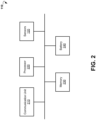
- FIG. 2 is a block diagram illustrating components of wearable device 110, according to an example embodiment.
- the example wearable device 110 may include sensors 120, a communication unit 210, a processor 220, memory 230, and a battery 240.
- the communication unit 210 can be configured to communicate with a network such as the Internet, a Wide Area Network (WAN), a Local Area Network (LAN), a cellular network, and so forth, to send a data stream, for example sensor data, medical parameters, and messages concerning the health condition of a patient.
- a network such as the Internet, a Wide Area Network (WAN), a Local Area Network (LAN), a cellular network, and so forth, to send a data stream, for example sensor data, medical parameters, and messages concerning the health condition of a patient.
- the processor 220 can include hardware and/or software, which is operable to execute computer programs stored in memory 230.
- the processor 220 can use floating point operations, complex operations, and other operations, including processing and analyzing sensor data.
- the battery 240 is operable to provide electrical power for operation of other components of the wearable device 110.
- the battery 240 is a rechargeable battery.
- the battery 240 is recharged using inductive charging technology.
- the wearable device 110 may include additional or different components to provide a particular operation or functionality. Similarly, in other embodiments, the wearable device 110 includes fewer components that perform similar or equivalent functions to those depicted in FIG. 2 . For example, the wearable device 110 may further include a graphical display system to provide an alert message and display current values of the medical parameters to the patient. The wearable device 110 may also include a haptic device to alert the patient with vibrations. The wearable device 110 may also include an audio signaling device, for example, a beeper or a speaker, to provide sound alerts to the patient.
- an audio signaling device for example, a beeper or a speaker
- FIG. 3 is a block diagram showing a list of example sensors 120, a list of example medical parameters 310, and a list of example chronic diseases 320.
- the sensors 120 may include optical sensors 222a and 222b, electrical sensors 224, and motion sensors 226.
- the medical parameters 310 determined based on the sensor data, include, but are not limited to, SpO 2 oxygen saturation, tissue oxygen saturation, cardiac output, vascular resistance, pulse rate, blood pressure, respiration, electrocardiogram (ECG) data, respiratory rate, and motion data.
- the chronic diseases 320 include but are not limited to congestive heart failure (CHF), hypertension, arrhythmia, asthma, chronic obstructive pulmonary disease (COPD), hypoglycemia, sleep apnea, and Parkinson's disease.
- CHF congestive heart failure
- COPD chronic obstructive pulmonary disease
- hypoglycemia sleep apnea
- Parkinson's disease the progression of which can be tracked based on changes of the medical parameters, include but are not limited to congestive heart failure (CHF), hypertension, arrhythmia, asthma, chronic obstructive pulmonary disease (COPD), hypoglycemia, sleep apnea, and Parkinson's disease.
- CHF congestive heart failure
- COPD chronic obstructive pulmonary disease
- hypoglycemia sleep apnea
- sleep apnea sleep apnea
- Parkinson's disease the progression of which can be tracked based on changes of the medical parameters
- the optical sensors 222a and 222b can be operable to measure medical parameters associated with blood flow in blood vessels using changing absorbance of light at different wavelengths in blood and skin.
- the data from optical sensors 222a and 222b can be used to determine multiple medical parameters, including but not limited to: SpO 2 oxygen saturation, cardiac output, vascular resistance, pulse rate, and respiratory rate.
- cardiac rhythms for example, atrial fibrillation, rapid rhythms, and slow rhythms.
- respiratory rate can be derived from a sinus arrhythmia waveform.
- the sinus arrhythmia waveform can be obtained based on intervals between subsequent heart beats (RR intervals) measured by the optical sensors 222a and 222b using the fact that the rhythm of the heart beats is modulated by human breathing.
- the electrical sensors 224 can be operable to obtain ECG activity data of the patient.
- the ECG activity data includes a characteristic electrically-derived waveform of a heart activity.
- the ECG data can include a number of components, whose characteristics (timing, amplitude, width, and so forth), alone or in combination, can provide a picture of cardiac and overall health.
- the ECG data is typically derived by measurements from one or more sets of leads (groups of electrodes comprising grounded circuits), such that the exact characteristics of the resulting waveforms is a function of the electrical and spatial vectors of the electrode positions relative to the heart.
- each of the component parameters can indicate health status, physical or psychological stress, or trends of disease conditions.
- Various cardiovascular parameters can be extracted from the ECG alone (such as a heart rate for example), or in combination with other physiological measurements.
- ECG of the patient can be measured via the electrical sensors 224. Since measurements are taken from a wrist of the patient, electrodes of the electrical sensors 224 should be located very close to each other on a wearable device. Therefore, the ECG data may contain noise. Averaging of several subsequent intervals of the ECG data between heart beats can be used to cancel out noise in ECG data. To determine intervals between two subsequent heart beats, the PPG signals as measured by optical sensors 222a and 222b can be used as a reference. In some embodiments, an arrhythmia analysis can be carried out using the ECG data and data concerning cardiac output and pulse rate.
- motion sensors 226 include an accelerometer, a gyroscope, and an Inertial Measurement Unit (IMU).
- the motion data obtained via motion sensors 226 can provide parameters of body movement and tremor.
- the motion data can allow tracking the progression or remission of a motor disease, Parkinson's disease, and physical condition of the patient.
- the motion data can be analyzed to determine whether the patient is likely to fall.
- the motion data can be analyzed in time domain and frequency domain. By tracking amplitudes of movement of the patient it can be determined if the patient's movements become slower (i.e., the patient becomes sluggish) or the patient is not moving at all. Additionally, according to example embodiments of the present disclosure, the motion data can be analyzed to determine a respiratory rate of the patient.
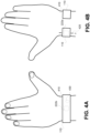
- FIG. 4A and FIG. 4B are schematic diagrams illustrating an example wearable device 110.
- the wearable device 110 can be carried out in a shape of an open bangle.
- the FIG. 4A shows a dorsal side of a patient's hand 410 and the wearable device 110 placed on the patient's wrist.
- FIG. 4B shows a palmar side of the patient's hand 410 and wearable device 110.
- the wearable device 110 can be designed to apply pressure at an area of skin surface covering a radial artery 420. In comparison to wristbands and straps, an open bangle may be more comfortable to wear by a patient since no pressure is applied to the middle area inside the wrist.
- the wearable device 110 can include optical sensors 222a and 222b located on an inner side of the wearable device 110. When the wearable device 110 is worn on the patient's hand, the inner side of the wearable device 110 can be in continuous contact with a surface of the skin of the patient's hand 410.
- the optical sensor 222a is located as close as possible to cover the skin area covering an artery of the wrist, for example the radial artery 420.
- the optical sensor 222b is located on the dorsal side of the wrist.
- the optical sensors 222a and 222b can be configured to be in a continuous contact with the skin of the patient 130.
- the optical sensors 222a may include multiple light sensors 440 (photodetectors), to measure the reflected light, and multiple light transmitters 450 (for example, Light Emission Diodes (LEDs)).
- the number and location of the light sensors 440 and light transmitters 450 can be chosen such that in case of an accidental displacement of the wearable device, at least one of the light sensors is still located sufficiently close to the radial artery.
- a signal from those photoelectric cells that provides the strongest or otherwise determined best output can be selected for further processing in order to obtain medical parameters using methods of pulse (reflectance) oximetry.
- the wearable device 110 can be configured to apply a predetermined amount of pressure to the wrist each time the user wears the wearable device to allow the same conditions for the reflection of the light from the skin.
- the optical sensor 222b may include elements analogous to the elements of the optical sensor 222a.
- the signals measured by optical sensors 222a and 222b can be used to determine oxygen saturation, heart rate, cardiac output, and other parameters using pulse oximetry methods.
- Oxygen saturation is the relative proportion (typically expressed as percentage) of oxygen dissolved in blood, as bound to hemoglobin, relative to non-oxygen-bound hemoglobin. Oxygen saturation is important in clinical monitoring of surgical anesthesia, and in monitoring and assessment of various clinical conditions such as COPD and asthma. In healthy individuals, oxygen saturation is over 95%. Direct measurement can be made from arterial blood sample, but drawing blood is an invasive procedure, and, except for a few controlled environments (e.g., during a surgery) cannot be easily performed continuously.
- Pulse oximetry can yield a quantity called SpO2 (saturation of peripheral oxygen), an accepted estimate of arterial oxygen saturation, derived from optical characteristics of blood using transmission of light through a thin part of a human body (for example, a fingertip or an earlobe (in the most common transmissive application mode)).
- Reflectance pulse oximetry can be used to estimate SpO2 using other body sites.
- the reflectance pulse oximetry does not require a thin section of the person's body and is therefore suited to more universal application such as the feet, forehead, and chest, but it has some serious issues due to the light reflected from non-pulsating tissues.
- an indirect measurement can be performed by tracking tissue oxygen saturation.
- the measurement of oxygen saturation is commonly used to track progression of heart disease or lung disease.
- tissue oxygen saturation can be measured by sensing the skin color near the radial artery. For example, if the wearable device 110 moves so that optical sensor 222a is not covering the radial artery, measurements of tissue saturation near the radial artery can be used as a backup to provide values for oxygen saturation.
- the optical sensor 222a can be configured to measure an infrared wavelength PPG signal I a ir and a red wavelength PPG signal I a red near a blood artery of the wrist of the patient (for example, the radial artery 420).
- the infrared wavelength PPG signal can be obtained by emitting, by the light transmitters 450, an infrared wavelength light and detecting, by the light sensor 440, intensity of infrared light reflected from the skin and blood vessels of the patient.
- the red wavelength PPG signal can be obtained by emitting, by the light transmitters 450, a red wavelength light and detecting, by the light sensor 440, intensity of red light reflected from the skin and blood vessels of the patient.
- the optical sensor 222a can be configured to measure an infrared wavelength PPG signal I b ir and a red wavelength PPG signal I b red from the palmar side of the wrist of patient.
- the wearable device 110 can include a gyroscope 430.
- the gyroscope 430 can be located at any point within the wearable device 110.
- the gyroscope may include a triple axis Micro Electro-Mechanical Systems (MEMS) gyroscope.
- MEMS Micro Electro-Mechanical Systems
- the gyroscope 430 can measure rotation around three axes: x, y, and z.
- a gyroscope signal measured by the gyroscope 430 can be analyzed to determine a respiratory rate of a patient.
- the respiratory rate which is a vital sign, is typically expressed as the number of breaths per minute. Typical adult resting respiratory rate is about 16-20 breaths per minute. Extreme variations can result from physical or psychological stress. The respiratory rate is often affected in chronic disease states, particularly in pulmonary and cardiovascular disease. Extreme short-term changes may be associated with acute disease episodes, particularly in chronically ill patients.
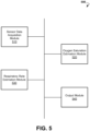
- FIG. 5 is a block diagram showing components of a system 500 for monitoring health status of people suffering from chronic diseases, according to an example embodiment.
- the system 500 can include a sensor data acquisition module 510, an oxygen saturation estimation module 520, a respiratory rate estimation module 530, and an output module 540.
- the modules 510-540 are implemented as chipsets included in the wearable device 110.
- the modules 520, 530, and 540 can be stored as instructions in memory of the wearable device 110, mobile device 140, or computing cloud 150, and executed by a processor.
- the sensor data acquisition module 510 is configured to receive and digitize the sensor data.
- the sensor data acquisition module 510 can include one or more analog-to-digital converters to transform the electrical signals from sensors 120 to digital signals and provide the digital signal to modules 520-540 for further analysis.
- the data processing module is configured to analyze the infrared wavelength PPG signals and the red wavelength PPG signals recorded by the optical sensor 222a and 222b to obtain oxygen saturation using the methods of pulse oximetry.
- the methods for pulse oximetry are based on the fact that oxygenated hemoglobin absorbs more infrared light while deoxygenated hemoglobin absorbs more red light.
- the ratio R can indicate a ratio between oxygenated hemoglobin and deoxygenated hemoglobin.
- the ratio R can be converted to a corresponding oxygen saturation (SpO 2 ) value via an empirically-derived look-up table.
- the infrared wavelength PPG signal can be shifted by a parameter L ir and the red wavelength PPG signal can be shifted by a parameter L red .
- the ratio R 1 can be further used to obtain the oxygen saturation via an empirically-derived look-up table or function.
- the parameters L red and L ir can be pre-determined in a calibration process.
- the oxygen saturation estimation module 520 may be configured to calculate a ratio R a .
- the oxygen saturation estimation module 520 may be configured to calculate a ratio R b .
- the PPG signals I a ir , I b red , I b ir , and I b red can be recorded substantially simultaneously.
- the ratio R a is determined from PPG signals recorded by optical sensor 222a from the palmar side of the wrist near a blood artery, the value of the ratio R a may be sensitive to location of light transmitters 450 and light sensors 440 relative to the blood artery.
- error of value oxygen saturation (SpO 2 ) determined based on ratio R a decreases with increase of values for oxygen saturations.
- the optical sensor 222a located at the radial artery on the palmar side of the wrist may provide a PPG signals with a Signal-to-Noise Ratio (SNR) higher than the SNR of the PPG signal for optical sensor 222b located on the dorsal side of the wrist.
- SNR Signal-to-Noise Ratio
- a location of an optical sensor near the radial artery is preferable over locations near fingertip or dorsal side of the wrist.
- Optical sensors located at a fingertip or on the dorsal side of the wrist can measure PPG signals received from small blood vessels.
- the quality of the PPG measurements received from the small blood vessels may be decreased due to several factors.
- One of the factors causing decrease in the quality of the PPG measurements includes possible constriction of small vessels due to low ambient temperatures.
- Another factor causing decrease in the quality of the PPG measurements includes a darker color of the skin covering the small blood vessels, which may lead to a decrease of the SNR in the PPG signals.
- the ratio R b is determined from PPG signals recorded at dorsal side of the wrist, which does not include pulsatile blood vessels. Therefore, the ratio R b can be assumed to be independent on location of the light transmitters and light sensors of the optical sensor 222b relative to the surface of the dorsal side of the wrist.
- PPG signals I b ir , and I b red recorded by the optical sensor 222b are of a good quality, that is having a high SNR (as defined above)
- the ratio R b obtained using the PPG signals I b ir , and I b red can be used to calibrate the PPG signals I a ir and I a red recorded by the optical sensor 222a.
- the ratio R a can be found by using the formula (2) and the ratio R b can be found by using formula (1).
- the ratio R b can be further used as R true (the "gold standard” measurement) to optimize the parameters L red and L ir in formula (2).
- the PPG signals measured by the optical sensor 222b on the dorsal side of the wrist can be used to calibrate the optical sensor 222a on the palmar side.
- the calibration process can be carried out each time the patient wears the wearable device 110.
- the calibration process can be also performed if a value of the oxygen saturation determined by using the PPG signals measured by the optical sensor 222a is outside a pre-determined range.
- the ratio R b can be used to correct a value for ratio R a .
- the ratio R a and ratio R b can be fused to obtain a ratio R.
- the ratio R can be further used to determine value of the oxygen saturation via an empirically-derived look-up table.
- the weight ⁇ can be determined as a function of SNR of PPG signal I b ir or PPG signal I b red measured at the palmar side of the wrist. Higher values of the weight ⁇ may correspond to higher values of the SNR of PPG signals I b ir , or I b red since a higher SNR signal is more reliable for determining ratio R.
- a weighted average of the ratio R a and ratio R b can provide a better estimate for the ratio R because measurement errors of the optical sensor 222a and 222b are independent of each other.
- the ratio R a can be given a larger weight because a measurement obtained on the palmar side of the wrist and near the radial artery may provide more information for core blood pressure and oxygen saturation than a measurement obtained from small vessels on the dorsal side of the wrist.
- weight ⁇ can be determined as a function of a perfusion index.
- the perfusion index is a ratio of the pulsatile blood flow to the non-pulsatile static blood flow in patient's peripheral tissue.
- the perfusion index can be estimated based on a PPG signal I b ir or a PPG signal I b red measured at the dorsal side of the wrist.
- FIG. 6A shows a plot 600A of an example PPG signal 610 which represents an amount of light received by a photodetector of optical sensor 222b.
- the perfusion index can be calculated as a ratio of difference 620 of the amount of light received by the photodetector between vasoconstriction and vascular dilation to the total amount 630 of light received by the photodetector.
- the larger the perfusion index the more accurate the measurement of oxygen saturation. Therefore, the perfusion index can be used as an indicator of quality of the PPG signal.
- the ratio R b obtained using the PPG signals I b ir and I b red can be used to correct the ratio R a using formula (3).
- the ratio R b can be also used to determine parameters L red and L ir in formula (2) for shifting PPG signals I a red and I a ir and, thereby, calibrate the optical sensor 222a disposed at the palmar side of the wrist.
- FIG. 6B shows an example function 600B for determining the weight ⁇ based on the value of perfusion index.
- the value of the perfusion index can be found based on the PPG signal I b ir or the PPG signal I b red measured at the dorsal side of wrist of a patient.
- the shape of function 600 can be determined in a calibration process.
- the weight ⁇ increases with an increase of the value for the perfusion index.
- the respiratory rate estimation module 530 is configured to analyze the gyroscope signal (rotation around three axes x, y, and z) measured by the gyroscope 430 at a wrist to obtain respiratory rate of a patient. It was found in tests performed by inventor that the gyroscope signal measured at the wrist of the patient includes data due to a cyclical motion of the chest of the patient. During the tests, a gyroscope signal measured by a gyroscope disposed at a wrist of a patient and a reference gyroscope signal measured by a gyroscope disposed in a chest strap at the chest of the patient were recorded simultaneously.
- a spectral analysis of the gyroscope signal measured at the wrist and the reference gyroscope signal measured at the chest were performed.
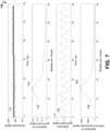
- a comparison of the spectra of the signals shows that the gyroscope signal measured at the wrist contains a frequency corresponding to the number of breaths of patient as determined based on the reference gyroscope signal measured at the chest.
- FIG. 7 shows plot 700 of example gyroscope signal 710 measured at a wrist, spectrum 720 of the gyroscope signal 710, reference gyroscope signal 730 measured at the chest, and spectrum 740 of the reference gyroscope signal 730.
- the spectrum 720 of the gyroscope signal 710 includes a peak 750, which corresponds to a peak 760 in spectrum 740 of the reference gyroscope signal 730.
- the frequency at the peak 750 corresponds to the respiratory rate.
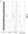
- FIG. 8 shows plot 800 of example gyroscope signal 810 measured at a wrist, spectrum 820 of the gyroscope signal 810, reference gyroscope signal 830 measured at the chest, and spectrum 840 of the reference gyroscope signal 830.
- the SNR of gyroscope signal 810 is higher than SNR of the gyroscope signal 710 shown in FIG. 7 .
- the spectrum 820 of the gyroscope signal 810 includes a peak 850 which corresponds to peak 860 in spectrum 840 of the reference gyroscope signal 830.
- the frequency at the peak 850 corresponds to the respiratory rate.
- the respiratory rate estimation module 530 may receive the gyroscope signal measured by the gyroscope 430 at the wrist of the patient and perform the spectral analysis of the gyroscope signal to obtain a spectrum of the gyroscope signal in a pre-determined range.
- the pre-determined range can be selected to cover a range of typical values for the respiratory rate of a human (for example, 6-18 breaths per minute).
- the pre-determined range may include a range of 0 to 50 breaths per minute.
- the spectral analysis may include fast Fourier transform, averaged periodograms (Bartlett's method), Welch's method, least-squares spectral analysis, and so forth.
- the respiratory rate estimation module 530 can be further configured to determine a position of a peak in the spectrum that corresponds to the number of breaths of a patient per minute (the respiratory rate). In some embodiments, the respiratory rate estimation module 530 can be configured to select the strongest peak in the pre-determined range. As seen in FIG. 7 and FIG. 8 , the spectrum of the gyroscope signal can be contaminated by a noise caused by movement of the patient. Typically, the noise is of a low frequency. Therefore, in the spectrum, the frequencies caused by the noise may interfere with the frequency corresponding to the respiratory rate.
- the signal s(t) is represented by peaks at frequencies n* ⁇ , wherein amplitudes of the peaks descend with the increase of n.
- This pattern can be searched in a spectrum of the gyroscope signal measured by the gyroscope at a wrist of patient to confirm that a correct peak was assigned to the respiratory rate.
- the respiratory rate estimation module 530 can confirm that the strongest peak in the spectrum represents breathing of the patient and not caused by movement noise of the patient.
- the respiratory rate estimation module 530 can be configured to determine that the spectrum includes one or more further peaks with descending amplitudes, such as the further peaks corresponding to frequencies n * ⁇ , wherein ⁇ is a frequency corresponding to the strongest peak, and n is a natural number. Based on the determination, the respiratory rate estimation module 530 can assign value ⁇ to the value of the respiratory rate.
- the output module 540 is configured to provide reports and alert messages regarding a health status of the patient.
- the output module 540 may be configured to display via a graphical display system of the wearable device 110 or the mobile device 140.
- the output module 540 may determine that the respiratory rate of the patient is near or outside of a typical range (for example, 6-18 breaths per minute).
- the output module 540 may also determine that the value of oxygen saturation of the patient is below a predetermined threshold.
- the output module 540 may provide an alert message to the patient via a graphical display system of the wearable device 110 or/and mobile device 140.
- the alert message may include an advice to take medication or contact a doctor.
- the output module may also send a warning message, via the communication unit of the wearable device 110 and/or mobile device 140, to a computing device of a relative, a doctor, or a caretaker of the patient.
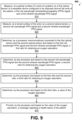
- FIG. 9 is a flow chart diagram showing example method 900 for monitoring oxygen saturation of a patient.
- the method 900 may be implemented in system 100.
- the method 900 may commence with measuring at a palmar surface of a wrist of the patient, by a first optical sensor, a first red wavelength PPG signal and a first infrared wavelength PPG signal.
- the first optical sensor can be embedded into a wearable device disposed around the wrist of the patient.
- the method 900 may proceed with measuring, at a dorsal surface of the wrist, by a second optical sensor disposed in the wearable device, a second red wavelength PPG signal and a second infrared wavelength PPG signal.
- the second red wavelength PPG signal and the second infrared wavelength PPG signal can be measured substantially simultaneously with the first red wavelength PPG signal and the first infrared wavelength PPG signal.
- the method 900 may continue with determining, by a processor communicatively connected to the first optical sensor and the second optical sensor and based on the first red wavelength PPG signal and the first infrared wavelength PPG signal, a first ratio for obtaining an oxygen saturation.
- the method 900 may determine, by the processor and based on the second red wavelength PPG signal and the second infrared wavelength PPG signal, a second ratio for obtaining the oxygen saturation.
- the method 900 may determine, by the processor and based on the first ratio and the second ratio, a third ratio for obtaining an oxygen saturation.
- the method 900 may determine, by the processor and based on the third ratio, a value of the oxygen saturation.
- the method 900 may include providing, by the processor and based on the value of the oxygen saturation, a message regarding a health status of the patient.
- the message may include a warning against upcoming episode or worsening of a chronic disease of the patient, for which the oxygen saturation is one of the indicators. Upon receiving such a warning, preventive measures can be taken to reduce the severity of upcoming or worsening of the chronic disease.
- the message may include an advice to take a medicine or to contact a doctor.
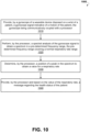
- FIG. 10 is a flow chart diagram showing an example method 1000 for monitoring respiratory rate of a patient.
- the method 1000 may be implemented in system 100.
- the method 1000 may commence with providing, by a gyroscope of a wearable device disposed on a wrist of a patient, a gyroscope signal indicative of a motion of the patient.
- the gyroscope can be communicatively coupled with a processor.
- the method 1000 may proceed with performing, by the processor, a spectral analysis of the gyroscope signal to obtain a spectrum in a pre-determined frequency range, the predetermined frequency range covering a normal respiratory rate range.
- the method 1000 may determine, by the processor, a position of a peak in the spectrum to obtain a value for a respiratory rate.
- the method 1000 may provide, by the processor and based on the value of the respiratory rate, a message regarding the health status of the patient.
- the method 1000 may determine, by the processor, that the value of the respiratory rate is outside of the normal respiratory rate range and provide, by the processor, an alert message regarding the health status of the patient based on the determination that the value of the respiratory rate is outside of the normal respiratory rate range.
- the alert message may include a warning against upcoming or worsening of a chronic disease from which the patients suffers, for which respiratory rate is one of the indicators.
- preventive measures can be taken to reduce the severity of upcoming or worsening of a chronic disease.
- the message may include an advice to take a medication or to contact a doctor.
Landscapes
- Health & Medical Sciences (AREA)
- Life Sciences & Earth Sciences (AREA)
- Engineering & Computer Science (AREA)
- Biomedical Technology (AREA)
- Medical Informatics (AREA)
- Public Health (AREA)
- Physics & Mathematics (AREA)
- General Health & Medical Sciences (AREA)
- Pathology (AREA)
- Biophysics (AREA)
- Veterinary Medicine (AREA)
- Heart & Thoracic Surgery (AREA)
- Molecular Biology (AREA)
- Surgery (AREA)
- Animal Behavior & Ethology (AREA)
- Physiology (AREA)
- Cardiology (AREA)
- Pulmonology (AREA)
- Artificial Intelligence (AREA)
- Signal Processing (AREA)
- Psychiatry (AREA)
- Computer Vision & Pattern Recognition (AREA)
- Epidemiology (AREA)
- Primary Health Care (AREA)
- Data Mining & Analysis (AREA)
- General Business, Economics & Management (AREA)
- Business, Economics & Management (AREA)
- Databases & Information Systems (AREA)
- Optics & Photonics (AREA)
- Spectroscopy & Molecular Physics (AREA)
- Measurement Of The Respiration, Hearing Ability, Form, And Blood Characteristics Of Living Organisms (AREA)
- Measuring Pulse, Heart Rate, Blood Pressure Or Blood Flow (AREA)
Applications Claiming Priority (3)
| Application Number | Priority Date | Filing Date | Title |
|---|---|---|---|
| US16/132,224 US10952638B2 (en) | 2015-06-12 | 2018-09-14 | System and method for monitoring respiratory rate and oxygen saturation |
| PCT/IL2019/051018 WO2020053858A1 (fr) | 2018-09-14 | 2019-09-12 | Système et procédé de surveillance de la fréquence respiratoire et de la saturation en oxygène |
| EP19859532.4A EP3849407B1 (fr) | 2018-09-14 | 2019-09-12 | Système et procédé de surveillance de la fréquence respiratoire et de la saturation en oxygène |
Related Parent Applications (2)
| Application Number | Title | Priority Date | Filing Date |
|---|---|---|---|
| EP19859532.4A Division EP3849407B1 (fr) | 2018-09-14 | 2019-09-12 | Système et procédé de surveillance de la fréquence respiratoire et de la saturation en oxygène |
| EP19859532.4A Division-Into EP3849407B1 (fr) | 2018-09-14 | 2019-09-12 | Système et procédé de surveillance de la fréquence respiratoire et de la saturation en oxygène |
Publications (1)
| Publication Number | Publication Date |
|---|---|
| EP4218558A1 true EP4218558A1 (fr) | 2023-08-02 |
Family
ID=69778482
Family Applications (2)
| Application Number | Title | Priority Date | Filing Date |
|---|---|---|---|
| EP23162749.8A Withdrawn EP4218558A1 (fr) | 2018-09-14 | 2019-09-12 | Système et procédé de surveillance de la fréquence respiratoire et de la saturation en oxygène |
| EP19859532.4A Active EP3849407B1 (fr) | 2018-09-14 | 2019-09-12 | Système et procédé de surveillance de la fréquence respiratoire et de la saturation en oxygène |
Family Applications After (1)
| Application Number | Title | Priority Date | Filing Date |
|---|---|---|---|
| EP19859532.4A Active EP3849407B1 (fr) | 2018-09-14 | 2019-09-12 | Système et procédé de surveillance de la fréquence respiratoire et de la saturation en oxygène |
Country Status (2)
| Country | Link |
|---|---|
| EP (2) | EP4218558A1 (fr) |
| WO (1) | WO2020053858A1 (fr) |
Families Citing this family (9)
| Publication number | Priority date | Publication date | Assignee | Title |
|---|---|---|---|---|
| US11160459B2 (en) | 2015-06-12 | 2021-11-02 | ChroniSense Medical Ltd. | Monitoring health status of people suffering from chronic diseases |
| US10952638B2 (en) | 2015-06-12 | 2021-03-23 | ChroniSense Medical Ltd. | System and method for monitoring respiratory rate and oxygen saturation |
| US11712190B2 (en) | 2015-06-12 | 2023-08-01 | ChroniSense Medical Ltd. | Wearable device electrocardiogram |
| US11464457B2 (en) | 2015-06-12 | 2022-10-11 | ChroniSense Medical Ltd. | Determining an early warning score based on wearable device measurements |
| US11160461B2 (en) | 2015-06-12 | 2021-11-02 | ChroniSense Medical Ltd. | Blood pressure measurement using a wearable device |
| US10687742B2 (en) | 2015-06-12 | 2020-06-23 | ChroniSense Medical Ltd. | Using invariant factors for pulse oximetry |
| US11000235B2 (en) | 2016-03-14 | 2021-05-11 | ChroniSense Medical Ltd. | Monitoring procedure for early warning of cardiac episodes |
| TWI812200B (zh) * | 2022-04-29 | 2023-08-11 | 緯創資通股份有限公司 | 具有心率偵測之穿戴式裝置、動態心率偵測方法及非暫態電腦可讀取儲存媒體 |
| CN116649930A (zh) * | 2023-06-12 | 2023-08-29 | 深圳市我家守护科技有限公司 | 一种多元参数健康监测装置及系统 |
Citations (3)
| Publication number | Priority date | Publication date | Assignee | Title |
|---|---|---|---|---|
| US20140055352A1 (en) * | 2012-11-01 | 2014-02-27 | Eyecam Llc | Wireless wrist computing and control device and method for 3D imaging, mapping, networking and interfacing |
| US20180042513A1 (en) * | 2015-11-24 | 2018-02-15 | Medibotics Llc | Arcuate Wearable Device with a Circumferential or Annular Array of Spectroscopic Sensors for Measuring Hydration Level |
| US20180132794A1 (en) * | 2015-06-12 | 2018-05-17 | ChroniSense Medical Ltd. | Determining an Early Warning Score Based On Wearable Device Measurements |
Family Cites Families (9)
| Publication number | Priority date | Publication date | Assignee | Title |
|---|---|---|---|---|
| CA2668400C (fr) * | 2006-11-01 | 2012-05-15 | Biancamed Ltd. | Systeme et methode de suivi de parametres respiratoires |
| US9173594B2 (en) * | 2010-04-19 | 2015-11-03 | Sotera Wireless, Inc. | Body-worn monitor for measuring respiratory rate |
| JP5740006B2 (ja) * | 2011-10-26 | 2015-06-24 | 株式会社日立製作所 | 呼吸測定システム及びrem睡眠判定システム |
| US20160007935A1 (en) | 2014-03-19 | 2016-01-14 | Massachusetts Institute Of Technology | Methods and apparatus for measuring physiological parameters |
| EP4306041A1 (fr) * | 2015-01-06 | 2024-01-17 | David Burton | Systèmes de surveillance pouvant être mobiles et portes |
| US10952638B2 (en) * | 2015-06-12 | 2021-03-23 | ChroniSense Medical Ltd. | System and method for monitoring respiratory rate and oxygen saturation |
| US20200260962A1 (en) | 2015-11-09 | 2020-08-20 | Magniware Ltd. | System and methods for acquisition and analysis of health data |
| EP3383267B1 (fr) * | 2015-12-02 | 2023-02-22 | Spry Health, Inc. | Systèmes et procédés de mesure de fréquence respiratoire non-invasive |
| WO2017140696A1 (fr) | 2016-02-15 | 2017-08-24 | Koninklijke Philips N.V. | Dispositif, système et procédé de détermination du rythme respiratoire d'un sujet |
-
2019
- 2019-09-12 EP EP23162749.8A patent/EP4218558A1/fr not_active Withdrawn
- 2019-09-12 EP EP19859532.4A patent/EP3849407B1/fr active Active
- 2019-09-12 WO PCT/IL2019/051018 patent/WO2020053858A1/fr not_active Ceased
Patent Citations (3)
| Publication number | Priority date | Publication date | Assignee | Title |
|---|---|---|---|---|
| US20140055352A1 (en) * | 2012-11-01 | 2014-02-27 | Eyecam Llc | Wireless wrist computing and control device and method for 3D imaging, mapping, networking and interfacing |
| US20180132794A1 (en) * | 2015-06-12 | 2018-05-17 | ChroniSense Medical Ltd. | Determining an Early Warning Score Based On Wearable Device Measurements |
| US20180042513A1 (en) * | 2015-11-24 | 2018-02-15 | Medibotics Llc | Arcuate Wearable Device with a Circumferential or Annular Array of Spectroscopic Sensors for Measuring Hydration Level |
Also Published As
| Publication number | Publication date |
|---|---|
| EP3849407A1 (fr) | 2021-07-21 |
| EP3849407A4 (fr) | 2022-09-07 |
| EP3849407C0 (fr) | 2024-01-31 |
| WO2020053858A1 (fr) | 2020-03-19 |
| EP3849407B1 (fr) | 2024-01-31 |
Similar Documents
| Publication | Publication Date | Title |
|---|---|---|
| US11571139B2 (en) | Wearable system and method for measuring oxygen saturation | |
| EP3849407B1 (fr) | Système et procédé de surveillance de la fréquence respiratoire et de la saturation en oxygène | |
| US11464457B2 (en) | Determining an early warning score based on wearable device measurements | |
| US20260090772A1 (en) | System and method for monitoring respiratory rate measurements | |
| EP3307146B1 (fr) | Surveillance de l'état de santé de personnes souffrant de maladies chroniques | |
| Castaneda et al. | A review on wearable photoplethysmography sensors and their potential future applications in health care | |
| EP3731744B1 (fr) | Détermination d'un score d'alerte précoce sur la base de mesures de dispositif portable | |
| US7570979B2 (en) | Methods and apparatus for patient monitoring | |
| Benedetti et al. | Heart rate detection by Fitbit ChargeHR™: A validation study versus portable polysomnography | |
| US20250295366A1 (en) | Monitoring of physiological parameters with wearable device | |
| US12178552B1 (en) | Systems and processes for detecting oxygen saturation and compensating for skin tone variation | |
| JP7109443B2 (ja) | 患者の監視 | |
| US20230007922A1 (en) | Method and System for Estimating Physiological Parameters Utilizing a Deep Neural Network to Build a Calibrated Parameter Model | |
| US20220202349A1 (en) | Multiparameter noninvasive sepsis monitor | |
| US20230157572A1 (en) | Continuous Self-Recalibrating System and Method for Monitoring Oxygen Saturation | |
| US10327648B2 (en) | Blood vessel mechanical signal analysis | |
| WO2025021578A1 (fr) | Masque fournissant une pression positive pour voies aériennes avec un capteur et un moniteur intégré | |
| WO2024157240A1 (fr) | Système d'auto-réétalonnage continu et procédé de surveillance de la saturation en oxygène | |
| US12575741B1 (en) | Systems and processes for detecting oxygen saturation and compensating for skin tone variation | |
| WO2024047621A1 (fr) | Procédé et système d'estimation de paramètres physiologiques à l'aide d'un réseau neuronal profond pour construire un modèle de paramètre étalonné | |
| Mainsah et al. | Design of a Dual Heart Rate Variability Monitor |
Legal Events
| Date | Code | Title | Description |
|---|---|---|---|
| PUAI | Public reference made under article 153(3) epc to a published international application that has entered the european phase |
Free format text: ORIGINAL CODE: 0009012 |
|
| STAA | Information on the status of an ep patent application or granted ep patent |
Free format text: STATUS: THE APPLICATION HAS BEEN PUBLISHED |
|
| AC | Divisional application: reference to earlier application |
Ref document number: 3849407 Country of ref document: EP Kind code of ref document: P |
|
| AK | Designated contracting states |
Kind code of ref document: A1 Designated state(s): AL AT BE BG CH CY CZ DE DK EE ES FI FR GB GR HR HU IE IS IT LI LT LU LV MC MK MT NL NO PL PT RO RS SE SI SK SM TR |
|
| STAA | Information on the status of an ep patent application or granted ep patent |
Free format text: STATUS: REQUEST FOR EXAMINATION WAS MADE |
|
| 17P | Request for examination filed |
Effective date: 20240201 |
|
| RBV | Designated contracting states (corrected) |
Designated state(s): AL AT BE BG CH CY CZ DE DK EE ES FI FR GB GR HR HU IE IS IT LI LT LU LV MC MK MT NL NO PL PT RO RS SE SI SK SM TR |
|
| STAA | Information on the status of an ep patent application or granted ep patent |
Free format text: STATUS: EXAMINATION IS IN PROGRESS |
|
| 17Q | First examination report despatched |
Effective date: 20240612 |
|
| 17Q | First examination report despatched |
Effective date: 20240625 |
|
| STAA | Information on the status of an ep patent application or granted ep patent |
Free format text: STATUS: THE APPLICATION IS DEEMED TO BE WITHDRAWN |
|
| 18D | Application deemed to be withdrawn |
Effective date: 20241026 |