EP4219074A1 - Systèmes et procédés de planification de la topographie d'une meule in situ, de la surveillance de la puissance et de la vitesse d'avance/de rotation - Google Patents
Systèmes et procédés de planification de la topographie d'une meule in situ, de la surveillance de la puissance et de la vitesse d'avance/de rotation Download PDFInfo
- Publication number
- EP4219074A1 EP4219074A1 EP23153553.5A EP23153553A EP4219074A1 EP 4219074 A1 EP4219074 A1 EP 4219074A1 EP 23153553 A EP23153553 A EP 23153553A EP 4219074 A1 EP4219074 A1 EP 4219074A1
- Authority
- EP
- European Patent Office
- Prior art keywords
- grinding wheel
- topography
- feed rate
- parameter
- grinding
- Prior art date
- Legal status (The legal status is an assumption and is not a legal conclusion. Google has not performed a legal analysis and makes no representation as to the accuracy of the status listed.)
- Granted
Links
Images


Classifications
-
- G—PHYSICS
- G05—CONTROLLING; REGULATING
- G05B—CONTROL OR REGULATING SYSTEMS IN GENERAL; FUNCTIONAL ELEMENTS OF SUCH SYSTEMS; MONITORING OR TESTING ARRANGEMENTS FOR SUCH SYSTEMS OR ELEMENTS
- G05B19/00—Program-control systems
- G05B19/02—Program-control systems electric
- G05B19/18—Numerical control [NC], i.e. automatically operating machines, in particular machine tools, e.g. in a manufacturing environment, so as to execute positioning, movement or co-ordinated operations by means of program data in numerical form
- G05B19/406—Numerical control [NC], i.e. automatically operating machines, in particular machine tools, e.g. in a manufacturing environment, so as to execute positioning, movement or co-ordinated operations by means of program data in numerical form characterised by monitoring or safety
- G05B19/4069—Simulating machining process on screen
-
- B—PERFORMING OPERATIONS; TRANSPORTING
- B23—MACHINE TOOLS; METAL-WORKING NOT OTHERWISE PROVIDED FOR
- B23Q—DETAILS, COMPONENTS, OR ACCESSORIES FOR MACHINE TOOLS, e.g. ARRANGEMENTS FOR COPYING OR CONTROLLING; MACHINE TOOLS IN GENERAL CHARACTERISED BY THE CONSTRUCTION OF PARTICULAR DETAILS OR COMPONENTS; COMBINATIONS OR ASSOCIATIONS OF METAL-WORKING MACHINES, NOT DIRECTED TO A PARTICULAR RESULT
- B23Q17/00—Arrangements for observing, indicating or measuring on machine tools
- B23Q17/09—Arrangements for observing, indicating or measuring on machine tools for indicating or measuring cutting pressure or for determining cutting-tool condition, e.g. cutting ability, load on tool
- B23Q17/0952—Arrangements for observing, indicating or measuring on machine tools for indicating or measuring cutting pressure or for determining cutting-tool condition, e.g. cutting ability, load on tool during machining
-
- B—PERFORMING OPERATIONS; TRANSPORTING
- B24—GRINDING; POLISHING
- B24B—MACHINES, DEVICES, OR PROCESSES FOR GRINDING OR POLISHING; DRESSING OR CONDITIONING OF ABRADING SURFACES; FEEDING OF GRINDING, POLISHING, OR LAPPING AGENTS
- B24B47/00—Drives or gearings; Equipment therefor
- B24B47/10—Drives or gearings; Equipment therefor for rotating or reciprocating working-spindles carrying grinding wheels or workpieces
- B24B47/18—Drives or gearings; Equipment therefor for rotating or reciprocating working-spindles carrying grinding wheels or workpieces for rotating the spindle at a speed adaptable to wear of the grinding wheel
-
- B—PERFORMING OPERATIONS; TRANSPORTING
- B24—GRINDING; POLISHING
- B24B—MACHINES, DEVICES, OR PROCESSES FOR GRINDING OR POLISHING; DRESSING OR CONDITIONING OF ABRADING SURFACES; FEEDING OF GRINDING, POLISHING, OR LAPPING AGENTS
- B24B49/00—Measuring or gauging equipment for controlling the feed movement of the grinding tool or work; Arrangements of indicating or measuring equipment, e.g. for indicating the start of the grinding operation
- B24B49/10—Measuring or gauging equipment for controlling the feed movement of the grinding tool or work; Arrangements of indicating or measuring equipment, e.g. for indicating the start of the grinding operation involving electrical means
-
- B—PERFORMING OPERATIONS; TRANSPORTING
- B24—GRINDING; POLISHING
- B24B—MACHINES, DEVICES, OR PROCESSES FOR GRINDING OR POLISHING; DRESSING OR CONDITIONING OF ABRADING SURFACES; FEEDING OF GRINDING, POLISHING, OR LAPPING AGENTS
- B24B49/00—Measuring or gauging equipment for controlling the feed movement of the grinding tool or work; Arrangements of indicating or measuring equipment, e.g. for indicating the start of the grinding operation
- B24B49/12—Measuring or gauging equipment for controlling the feed movement of the grinding tool or work; Arrangements of indicating or measuring equipment, e.g. for indicating the start of the grinding operation involving optical means
-
- B—PERFORMING OPERATIONS; TRANSPORTING
- B24—GRINDING; POLISHING
- B24B—MACHINES, DEVICES, OR PROCESSES FOR GRINDING OR POLISHING; DRESSING OR CONDITIONING OF ABRADING SURFACES; FEEDING OF GRINDING, POLISHING, OR LAPPING AGENTS
- B24B49/00—Measuring or gauging equipment for controlling the feed movement of the grinding tool or work; Arrangements of indicating or measuring equipment, e.g. for indicating the start of the grinding operation
- B24B49/14—Measuring or gauging equipment for controlling the feed movement of the grinding tool or work; Arrangements of indicating or measuring equipment, e.g. for indicating the start of the grinding operation taking regard of the temperature during grinding
-
- B—PERFORMING OPERATIONS; TRANSPORTING
- B24—GRINDING; POLISHING
- B24B—MACHINES, DEVICES, OR PROCESSES FOR GRINDING OR POLISHING; DRESSING OR CONDITIONING OF ABRADING SURFACES; FEEDING OF GRINDING, POLISHING, OR LAPPING AGENTS
- B24B49/00—Measuring or gauging equipment for controlling the feed movement of the grinding tool or work; Arrangements of indicating or measuring equipment, e.g. for indicating the start of the grinding operation
- B24B49/18—Measuring or gauging equipment for controlling the feed movement of the grinding tool or work; Arrangements of indicating or measuring equipment, e.g. for indicating the start of the grinding operation taking regard of the presence of dressing tools
- B24B49/183—Wear compensation without the presence of dressing tools
-
- B—PERFORMING OPERATIONS; TRANSPORTING
- B24—GRINDING; POLISHING
- B24B—MACHINES, DEVICES, OR PROCESSES FOR GRINDING OR POLISHING; DRESSING OR CONDITIONING OF ABRADING SURFACES; FEEDING OF GRINDING, POLISHING, OR LAPPING AGENTS
- B24B53/00—Devices or means for dressing or conditioning abrasive surfaces
-
- G—PHYSICS
- G05—CONTROLLING; REGULATING
- G05B—CONTROL OR REGULATING SYSTEMS IN GENERAL; FUNCTIONAL ELEMENTS OF SUCH SYSTEMS; MONITORING OR TESTING ARRANGEMENTS FOR SUCH SYSTEMS OR ELEMENTS
- G05B17/00—Systems involving the use of models or simulators of said systems
- G05B17/02—Systems involving the use of models or simulators of said systems electric
-
- G—PHYSICS
- G05—CONTROLLING; REGULATING
- G05B—CONTROL OR REGULATING SYSTEMS IN GENERAL; FUNCTIONAL ELEMENTS OF SUCH SYSTEMS; MONITORING OR TESTING ARRANGEMENTS FOR SUCH SYSTEMS OR ELEMENTS
- G05B19/00—Program-control systems
- G05B19/02—Program-control systems electric
- G05B19/18—Numerical control [NC], i.e. automatically operating machines, in particular machine tools, e.g. in a manufacturing environment, so as to execute positioning, movement or co-ordinated operations by means of program data in numerical form
- G05B19/404—Numerical control [NC], i.e. automatically operating machines, in particular machine tools, e.g. in a manufacturing environment, so as to execute positioning, movement or co-ordinated operations by means of program data in numerical form characterised by control arrangements for compensation, e.g. for backlash, overshoot, tool offset, tool wear, temperature, machine construction errors, load, inertia
-
- G—PHYSICS
- G05—CONTROLLING; REGULATING
- G05B—CONTROL OR REGULATING SYSTEMS IN GENERAL; FUNCTIONAL ELEMENTS OF SUCH SYSTEMS; MONITORING OR TESTING ARRANGEMENTS FOR SUCH SYSTEMS OR ELEMENTS
- G05B19/00—Program-control systems
- G05B19/02—Program-control systems electric
- G05B19/18—Numerical control [NC], i.e. automatically operating machines, in particular machine tools, e.g. in a manufacturing environment, so as to execute positioning, movement or co-ordinated operations by means of program data in numerical form
- G05B19/416—Numerical control [NC], i.e. automatically operating machines, in particular machine tools, e.g. in a manufacturing environment, so as to execute positioning, movement or co-ordinated operations by means of program data in numerical form characterised by control of velocity, acceleration or deceleration
- G05B19/4163—Adaptive control of feed or cutting velocity
-
- G—PHYSICS
- G05—CONTROLLING; REGULATING
- G05B—CONTROL OR REGULATING SYSTEMS IN GENERAL; FUNCTIONAL ELEMENTS OF SUCH SYSTEMS; MONITORING OR TESTING ARRANGEMENTS FOR SUCH SYSTEMS OR ELEMENTS
- G05B2219/00—Program-control systems
- G05B2219/30—Nc systems
- G05B2219/49—Nc machine tool, till multiple
- G05B2219/49168—Compensate feed as function of measured values and manual introduced values
-
- G—PHYSICS
- G05—CONTROLLING; REGULATING
- G05B—CONTROL OR REGULATING SYSTEMS IN GENERAL; FUNCTIONAL ELEMENTS OF SUCH SYSTEMS; MONITORING OR TESTING ARRANGEMENTS FOR SUCH SYSTEMS OR ELEMENTS
- G05B2219/00—Program-control systems
- G05B2219/30—Nc systems
- G05B2219/49—Nc machine tool, till multiple
- G05B2219/49171—Compensate for dressing amount
-
- G—PHYSICS
- G05—CONTROLLING; REGULATING
- G05B—CONTROL OR REGULATING SYSTEMS IN GENERAL; FUNCTIONAL ELEMENTS OF SUCH SYSTEMS; MONITORING OR TESTING ARRANGEMENTS FOR SUCH SYSTEMS OR ELEMENTS
- G05B2219/00—Program-control systems
- G05B2219/30—Nc systems
- G05B2219/49—Nc machine tool, till multiple
- G05B2219/49181—Calculation, estimation, creation of error model using measured error values
-
- G—PHYSICS
- G05—CONTROLLING; REGULATING
- G05B—CONTROL OR REGULATING SYSTEMS IN GENERAL; FUNCTIONAL ELEMENTS OF SUCH SYSTEMS; MONITORING OR TESTING ARRANGEMENTS FOR SUCH SYSTEMS OR ELEMENTS
- G05B2219/00—Program-control systems
- G05B2219/30—Nc systems
- G05B2219/50—Machine tool, machine tool null till machine tool work handling
- G05B2219/50311—Compensate tool wear by grinding tool to a known position
-
- G—PHYSICS
- G05—CONTROLLING; REGULATING
- G05B—CONTROL OR REGULATING SYSTEMS IN GENERAL; FUNCTIONAL ELEMENTS OF SUCH SYSTEMS; MONITORING OR TESTING ARRANGEMENTS FOR SUCH SYSTEMS OR ELEMENTS
- G05B2219/00—Program-control systems
- G05B2219/30—Nc systems
- G05B2219/50—Machine tool, machine tool null till machine tool work handling
- G05B2219/50312—Compensation of tool wear by adapting program to profile of tool
Definitions
- the present disclosure relates generally to grinding processes, and more particularly to systems and methods for grinding tool feed rate scheduling.
- a feed rate scheduling method comprising measuring the topography of a grinding wheel, calculating topography parameters of the grinding wheel, and calculating feed rate scheduling for a toolpath of the grinding wheel based on the topography parameter.
- the calculating the feed rate scheduling parameter comprises simulating a metal grinding process of the grinding wheel in a virtual machining simulation environment using the topography parameter.
- the step of calculating the feed rate scheduling parameter comprises monitoring an electric power used by the machine tool.
- the calculating the feed rate scheduling parameter comprises determining that the electric power is within a predetermined threshold.
- the topography parameter of the grinding wheel comprises a density of crystals at a given depth ( h ).
- the topography parameter of the grinding wheel comprises an area fraction of crystals protruding at a given depth ( h ).
- the feed rate scheduling parameter comprises an instantaneous grinding wheel feed rate.
- the topography parameter comprises a plurality of values as a function of distance with respect to a reference point on the grinding wheel, and the method further comprises limiting the topography parameter to a maximum distance ( h max ).
- the measuring the topography is performed using a microscopy process.
- a grinding process simulator for feed rate scheduling for a grinding wheel comprising a virtual machining simulation environment having a processor, and a tangible, non-transitory memory configured to communicate with the processor.
- the tangible, non-transitory memory has instructions stored thereon that, in response to execution by the processor, cause the virtual machining simulation environment to perform operations comprising measuring a topography of the grinding wheel of a machine tool, calculating a topography parameter using the topography, and calculating a feed rate scheduling parameter for a toolpath of the grinding wheel based on the topography parameter.
- a method comprising measuring a topography of a grinding wheel of a machine tool, calculating a plurality of topography parameters of the grinding wheel, wherein the plurality of topography parameters comprises at least one of a density of crystals at a given depth ( CCh )) of the grinding wheel, or an area fraction of crystals protruding at a given depth ( ⁇ ( h )) of the grinding wheel, and calculating a feed rate scheduling parameter for a toolpath of the grinding wheel based on the plurality of topography parameters.
- the measuring the topography is performed in-situ using a microscopy process.
- the method further comprises limiting a cutting depth of the grinding wheel to a maximum crystal height ( h max ) of the grinding wheel.
- any reference to singular includes plural embodiments, and any reference to more than one component or step may include a singular embodiment or step.
- any reference to attached, fixed, connected or the like may include permanent, removable, temporary, partial, full and/or any other possible attachment option.
- any reference to without contact (or similar phrases) may also include reduced contact or minimal contact.
- phrases such as “make contact with,” “coupled to,” “touch,” “interface with” and “engage” may be used interchangeably. Different cross-hatching is used throughout the figures to denote different parts but not necessarily to denote the same or different materials.
- Process physics modeling represents a new era in interrogation and optimization of toolpaths.
- its utility has been limited to feed scheduling to optimize for cycle time based on geometric criteria, but can be expanded to forces, power, temperatures, material change, life debit, tool wear/life, etc. through comprehensive inputs capturing details closer to actual prevailing conditions, as provided herein.
- incoming wheels from a supplier may result in producing more scrap parts and visual observations may indicate topographical differences with legacy wheels.
- feed rate scheduling accounts for topographical differences.
- quantitative metrics are desirable for comparison and communication to suppliers.
- Physics-based models may be used in grinding process planning driven by quantitative wheel topographic metrics. To these ends, it is desirable to formulate derivatives of topographic metrics to directly incorporate into physical models.
- Systems and methods of the present disclosure provide feed rate and spindle speed scheduling with real-time wheel topography and power monitoring with process modeling feedback.
- a machine tool 120 comprising a machine tool spindle 122 is illustrated, in accordance with various embodiments.
- a grinding wheel 110 is shown mounted to machine tool spindle 122.
- Machine tool spindle 122 may be a multi-axis machine tool spindle 122.
- the machine tool 120 rotates the grinding wheel 110 about a central longitudinal axis 190 and translates the grinding wheel 110 in one or more directions (e.g., a direction of translation 192) to machine a workpiece 124.
- workpiece 124 comprises a nickel-base metallic alloy material.
- Exemplary rotation is in a rotational direction about central longitudinal axis 190 at a rotational speed in excess of 10,000 rotations per minute (rpm) (e.g., in the range of 40,000 rpm-90,000 rpm in various embodiments).
- Exemplary translation is in a direction at an angle ⁇ with respect to central longitudinal axis 190 (e.g., in the illustrated embodiment the translational direction is at an angle ⁇ of ninety degrees with respect to central longitudinal axis 190) at a translational speed which is also referred to herein as a feed rate.
- the feed rate may be limited to a maximum feed rate, for example 100 inches per minute (ipm) in various embodiments.
- the feed rate may vary depending on the cutting effectiveness of grinding wheel 110 and the type of material being cut, among other factors.
- the traversal of the grinding wheel 110 removes material below a surface 105 and leaves a cut surface 106 on the workpiece 124.
- Grinding wheel 110 may comprise a rounded cutting surface.
- the machine tool 120 may further reorient the axis 190. Alternatively, or additionally, the machine tool 120 may reposition or reorient the workpiece 124.
- grinding wheel 110 includes a metallic body extending from an aft end 112 to a front (tip) end 114.
- grinding wheel 110 comprises an abrasive coating 116 on the tip end to increase cutting effectiveness.
- Abrasive coating 116 may be located on any periphery surface of grinding wheel 110 depending on which part of grinding wheel 110 is performing the grinding.
- abrasive coating 116 comprises a plurality of grains.
- abrasive coating 116 comprises a plurality of Cubic Boron Nitride (CBN) grains.
- abrasive coating 116 may be applied via an electroplating process.
- the present disclosure provides systems and methods for optimized feed rate scheduling (e.g., including choosing an optimum feed rate) of a grinding wheel 110 using grinding wheel topology measurements.
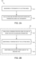
- Method 200 includes measuring a topography of a grinding wheel (step 210).
- step 210 may include taking a picture of the grinding wheel 110 using microscopy methods (e.g., optical scanning and white-light interferometry, pneumatic topographical measurements, laser topographical measurements, etc.).
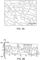
- FIG. 3A illustrates an exemplary picture of a surface of a grinding wheel. As illustrated in FIG. 3A , the surface of the grinding wheel comprises a plurality of grains, each grain capable of removing material from a workpiece at various rates, depths, and effectiveness.
- the grinding wheel may consist of a monolayer of CBN particles embedded in a typically nickel substrate designed with protrusion of the grains (crystals), as shown in FIG. 3A to remove material on the workpiece in a grinding operation.
- FIG. 3B further shows topographical data of a section of a grinding wheel surface with lateral axes 390 and topographical axis 392.
- step 210 may include measuring topographical data of a section of a grinding wheel surface with respect to lateral axes 390 and topographical axis 392.
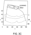
- FIG. 3C further shows topographical data of a grain (crystal) including the clearance angle of the grain.
- step 210 may include measuring the clearance angle of a grain of the grinding wheel surface.
- the workpiece may arrive at the grinding operation in the stock shape from casting, forging or metal additive routes from the primary manufacturing center (PMC).
- the grinding operation may be performed at a secondary operations center (SOC) with one or more grinding wheels.
- SOC secondary operations center
- the grinding wheel(s) may be created at a wheel manufacturing center (WMC), supplied by vendors, distributors, or other third parties.
- Electroplated (EP) grinding wheels tend to have very little tolerance for variation in process mechanics. Even slight variations may cause the abrasive mono-layer to be stripped and the component damaged when ground with a stripped wheel. Grinding wheels can be large in diameter with intricate edge-shapes or small in diameter such as a quill with simpler spherical, cylindrical, or toroidal shapes.
- the topographic data may be first corrected for curvature within its two lateral bounds, for example using the native software of the microscope, though in various embodiments non-native software of the microscope is used.
- the data may be converted to a point cloud in two lateral axes and one topographical axis.
- the data may then be imported and parsed in a scientific computing software. Then, within the two lateral bounds of the nominally flat surface, an interpolation for position along the topographical axis may be constructed.
- step 210 may include calculating values C ( h ) and ⁇ ( h ) using the topographical data.
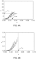
- h may be a distance or depth from a reference point on the grinding wheel (e.g., the highest point of the grinding wheel or the like). An example of data acquired from multiple areas in a single tool are shown in FIG. 4A and FIG. 4B .
- the ability to perform replicas on a wheel mounted on the spindle is desirable. Such a technique is non-invasive and impacts the production schedule minimally.
- the topography data may be processed offline to obtain various coefficient-e.g., C ( h ) and ⁇ ( h )-and a physics based process simulator, which takes the coefficients as input, may be made to output optimized feed-rates based on the prevailing topography of the wheel (see FIG. 5 ).
- Method 200 includes calculating one or more feed rate scheduling parameters using the topography (step 220).
- a flow chart 500 of a physics-based grinding process simulator 520 (also referred to herein as a virtual machining simulation environment), which takes the coefficients C(h) and ⁇ ( h ) as input parameters 510, is provided to output feed rate scheduling parameters 580, such as optimized feed-rates, based on the prevailing topography of the wheel.
- step 220 may be performed by physics-based grinding process simulator 520.
- the physics-based grinding process simulator 520 includes one or more controllers (e.g., processors) and one or more tangible, non-transitory memories capable of implementing digital or programmatic logic.
- the one or more controllers are one or more of a general purpose processor, digital signal processor (DSP), application specific integrated circuit (ASIC), field programmable gate array (FPGA), or other programmable logic device, discrete gate, transistor logic, or discrete hardware components, or any various combinations thereof or the like.
- System program instructions and/or controller instructions may be loaded onto a non-transitory, tangible computer-readable medium having instructions stored thereon that, in response to execution by a controller, cause the controller to perform various operations.
- non-transitory is to be understood to remove only propagating transitory signals per se from the claim scope and does not relinquish rights to all standard computer-readable media that are not only propagating transitory signals per se.
- non-transitory computer-readable medium and “non-transitory computer-readable storage medium” should be construed to exclude only those types of transitory computer-readable media which were found in In Re Nuijten to fall outside the scope of patentable subject matter under 35 U.S.C. ⁇ 101.
- Simulator 520 may be initiated by a user or other program and initial conditions and parameter limits may be set at step 522.
- Exemplary initial conditions include stickout length (e.g., measured in inches), drilling feed (e.g., measured in inches per minute (ipm)), rotational speed (e.g., measured in rpm), and step size for the iterative solver, among others.
- Exemplary parameter limits include maximum feed rate (i.e., the maximum translational speed; e.g., measured in ipm), among others.
- simulator 520 may use coefficient C ( h ) and ⁇ ( h ) to calculate optimized grinding wheel feed rates.
- the logic of calculating the optimized feed rates using the coefficients C ( h ) and ⁇ ( h ) rests on the power of applying the formulation everywhere that the grinding wheel is in contact with the workpiece.
- equation 1 and equation 2 may be used so that variable h can be solved from equation 3.
- ⁇ q " / V s
- q local material volume remove rate per unit area
- V s local peripheral speed of travel of grinding crystals relative to the part.
- q " may be derived using the shape and instantaneous trajectory of the wheel encompassing the instantaneous feed rate of the tool tip.
- q' Vd, where q' is the specific material removal rate, V is the feed rate (velocity), and d is the removing depth.
- Feed scheduling is primarily based on forces and h .
- the feed rate of the wheel directly impacts q " and thus ⁇ .
- grain penetration h and forces F total are simultaneously limited, choosing optimal feed rate to be the smaller value for chosen limits on h and F total.
- P pl " is the plowing force per unit area (MPa)
- ⁇ is the coefficient of sliding friction
- p a is the normal pressure due to sliding (N/mm 2 )
- a f is the wear flat to apparent area of contact ratio
- k 1 is the thrust to cutting chip-formation force ratio.
- Total force components in a portion are given by equation six (6).
- Global resultant forces on the tool may be obtained by summing contributions from all portions within the engagement contour (the contour of the tool in contact with the workpiece) vectorially.
- Equation seven vectorially expresses elemental normal ( dF n ) and tangential ( dF t ) forces on the portion as experienced by the tool.
- dF t tangential
- TCS tool coordinate system
- F t is the tangential (feed) force in (measured in Newtons (N))
- F n is the normal (thrust) force in SCSG, (N).
- simulator 520 may simulate a virtual grinding process using built-in physics based equations (see step 222 of FIG. 2B ).
- simulator 520 may calculate an updated feed rate scheduling parameter (e.g., instantaneous feed rate, cutting depth, and/or spindle speed).
- the updated feed rate scheduling parameter may be used during the next iteration to converge on one or more desired solutions.
- the feed rate scheduling parameter may be iteratively solved by simulating a metal grinding process (i.e., using physics based equations) of the grinding wheel in a virtual machining simulation environment (i.e., using software) using one or more topography parameters (i.e., C(h) and/or ⁇ ( h )).
- simulator 520 may calculate/monitor the temperature of the grinding wheel and power consumed by the tool machine (e.g., electric motor), respectively (see step 224 and step 226 of FIG. 2B ).
- simulator 520 may continue to iteratively solve the built in physics based equations to converge on a desired feed rate-e.g., based on desired temperature and power consumption, among other desired parameters.
- the simulator 520 may output the optimized feed rate scheduling parameter 580 (such as feed rate, cutting depth, spindle speed, etc.) to be implemented during a physical grinding process on an actual (as opposed to virtual) workpiece.
- the optimized feed rate scheduling parameter 580 such as feed rate, cutting depth, spindle speed, etc.
- Power monitoring in grinding processes may be performed using various methods. These methods range from using simple transducers to complete turn-key setups integrating with the machine controller. However, a missing component in legacy systems is the wheel condition input.
- the physics-based grinding modeling software of the present disclosure may be provided as an add-on to a virtual grinding modeling framework.
- the three components namely, a) grinding power monitoring, b) wheel topography measurement and a mathematical data-reduction algorithm and c) virtual grinding modeling framework can allow spindle speed and feed rate scheduling tuned to current state of the wheel. This approach expands the scope of use of power monitoring which currently is used merely to detect power excursions while investigating part quality deviations.
- the systems and methods of the present disclosure can also be useful in robotic grinding and deburring operations where belt power and topography can also be measured.
- the systems and methods of the present disclosure provide feed scheduling based on grinding power and wheel topography measurements in various wheel systems (vit., EP and MB) and configurations (machine tool, robot)
- the systems and methods of the present disclosure provide data from a microscope (e.g., as a surface STL file) and convert into an interpolation object in scientific computing software (e.g., MATHEMATICA ® ) to perform subsequent calculations.
- a microscope e.g., as a surface STL file
- scientific computing software e.g., MATHEMATICA ®
- C(h) and ⁇ ( h ) pertinent to electroplated wheels is explained here. Initially it is expected for C(h) to increase with h since the cross-sections cut through more and more grains, but eventually it is expected for C(h) to start to decrease with h since the cross-sections start to enter the nickel plating and multiple areas coalesce. Therefore, it is desirable for the data to be clipped at h max as shown in FIG. 4A .
- the ⁇ ( h ) data may also be clipped at h max , as shown in FIG. 4B , since from this limit onwards, the curve is expected to asymptotically tend to unity since it would start to include the nickel substrate encapsulation of the crystal.
- a limit h max may be imposed on the raw topographical data to capture the encapsulation effect of the nickel substrate. It is desirable for the grain penetration depth h to be limited to h max (for example a cutting depth of the grinding wheel may be limited to a maximum grain height), to ensure control over grain forces and proper chip evacuation. This tends to depend on average grain size d g , amount of encapsulation, and statistical protrusion of the grains.
- Grain penetration h can be solved as explained above with respect to equations 1 through 5. Different portions of the wheel are subject to different amounts of local material removal rate q" and possibly different peripheral velocity V s proportional to the rotation speed of the tool. Local forces and power contribution are calculated knowing local h . Therefore, it is desirable to control h in grinding with an EP wheel.
- the present disclosure provides the power-law formulation of the static grinding surface so that h is directly expressible as a function of ⁇ .
- a grinding procedure of the present disclosure can work on axis-symmetric wheels which either have straight-line or curvilinear profiles since local material removal rate q" drives the fine-tuned feed-rate.
- Another lever to control for his the rotational speed of the tool which directly changes the V at all locations on the tool.
- Power-law fits to C(h) and ⁇ ( h ) functions yield a simple way to compare wheels of same geometry but different grain and surface topographies.
- the power law fits carry over to process mechanics modeling to quantitatively predict forces, power, and temperature changes due to changing wheel topography metrics.
- ⁇ ( h ) is an intermediary metric, but it drives all other geometric and physical calculations. It is a measure of uniformity of grain protrusions on the wheel surface.
- Systems and methods of the present disclosure can be applied to substantially automated and robotically controlled grinding processes. Surprisingly, systems and methods of the present disclosure have shown that higher feed rates are sometimes beneficial to reducing part heating.
- the present disclosure provides a method for evaluating grinding wheel topography to: (a) perform feed-scheduling with prevailing wheel condition and power monitored, and (b) find disparities in various C ( h ) and ⁇ ( h ) curves from the same wheel to reveal poor wheel quality control at the secondary manufacturing center.
- the present disclosure provides a method for fine-tuning an existing grinding process for incoming wheel surface topographic metrics (a) using in-situ microscopy near the grinding operation, (b) using a simple feed over-ride for altered wheel topographic metrics, and/or (c) to use a simple altered rotational speed of the wheel or tool to achieve controlled grain penetration into the work material.
- the present disclosure provides process models which include actual topographic metrics data such as C ( h max ), h max to (a) control grain-penetration depth in electroplated wheels, and/or (b) to capture the effect of the extent of encapsulation of the crystals in the substrate on the process mechanics.
- actual topographic metrics data such as C ( h max ), h max to (a) control grain-penetration depth in electroplated wheels, and/or (b) to capture the effect of the extent of encapsulation of the crystals in the substrate on the process mechanics.
- references to "one embodiment”, “an embodiment”, “various embodiments”, etc. indicate that the embodiment described may include a particular feature, structure, or characteristic, but every embodiment may not necessarily include the particular feature, structure, or characteristic. Moreover, such phrases are not necessarily referring to the same embodiment. Further, when a particular feature, structure, or characteristic is described in connection with an embodiment, it is submitted that it is within the knowledge of one skilled in the art to affect such feature, structure, or characteristic in connection with other embodiments whether or not explicitly described. After reading the description, it will be apparent to one skilled in the relevant art(s) how to implement the disclosure in alternative embodiments.
Landscapes
- Engineering & Computer Science (AREA)
- Mechanical Engineering (AREA)
- Physics & Mathematics (AREA)
- General Physics & Mathematics (AREA)
- Automation & Control Theory (AREA)
- Human Computer Interaction (AREA)
- Manufacturing & Machinery (AREA)
- Constituent Portions Of Griding Lathes, Driving, Sensing And Control (AREA)
Applications Claiming Priority (1)
| Application Number | Priority Date | Filing Date | Title |
|---|---|---|---|
| US202263304436P | 2022-01-28 | 2022-01-28 |
Publications (2)
| Publication Number | Publication Date |
|---|---|
| EP4219074A1 true EP4219074A1 (fr) | 2023-08-02 |
| EP4219074B1 EP4219074B1 (fr) | 2025-12-24 |
Family
ID=85121919
Family Applications (1)
| Application Number | Title | Priority Date | Filing Date |
|---|---|---|---|
| EP23153553.5A Active EP4219074B1 (fr) | 2022-01-28 | 2023-01-26 | Systèmes et procédés de planification de la topographie d'une meule in situ, de la surveillance de la puissance et de la vitesse d'avance/de rotation |
Country Status (2)
| Country | Link |
|---|---|
| US (1) | US12589459B2 (fr) |
| EP (1) | EP4219074B1 (fr) |
Citations (5)
| Publication number | Priority date | Publication date | Assignee | Title |
|---|---|---|---|---|
| JP2006341358A (ja) * | 2005-06-10 | 2006-12-21 | Jtekt Corp | 主軸の回転に同期させて工具を往復運動させる工作機械の制御装置 |
| US7664565B2 (en) * | 2006-04-21 | 2010-02-16 | Thielenhaus Microfinish Corp. | Method for compensating wear of a finishing tool |
| US20150127139A1 (en) * | 2013-11-07 | 2015-05-07 | The Boeing Company | Real-Time Numerical Control Tool Path Adaptation Using Force Feedback |
| CN113084707A (zh) * | 2021-03-05 | 2021-07-09 | 华南理工大学 | 一种金刚石机械热化学修整能量的模糊控制方法 |
| US20210278817A1 (en) * | 2018-06-22 | 2021-09-09 | South China University Of Technology | Online precise control method for truncating parameters of microscale abrasive grains |
Family Cites Families (4)
| Publication number | Priority date | Publication date | Assignee | Title |
|---|---|---|---|---|
| US5044125A (en) | 1988-09-02 | 1991-09-03 | Cincinnati Milacron-Heald Corp. | Method and apparatus for controlling grinding processes |
| CN103105152B (zh) * | 2013-01-10 | 2015-08-26 | 西安交通大学 | 一种基于齿轮加工仿真模型的齿轮加工表面形貌分析方法 |
| US11484984B2 (en) | 2018-12-12 | 2022-11-01 | Agathon AG, Maschinenfabrik | Tool device and method for measuring a condition of a machining tool |
| CH716583A1 (de) * | 2019-09-13 | 2021-03-15 | Reishauer Ag | Verfahren zur Überwachung eines Bearbeitungsprozesses, bei dem Zahnflanken vorverzahnter Werkstücke mit einer Feinbearbeitungsmaschine bearbeitet werden. |
-
2023
- 2023-01-03 US US18/149,320 patent/US12589459B2/en active Active
- 2023-01-26 EP EP23153553.5A patent/EP4219074B1/fr active Active
Patent Citations (5)
| Publication number | Priority date | Publication date | Assignee | Title |
|---|---|---|---|---|
| JP2006341358A (ja) * | 2005-06-10 | 2006-12-21 | Jtekt Corp | 主軸の回転に同期させて工具を往復運動させる工作機械の制御装置 |
| US7664565B2 (en) * | 2006-04-21 | 2010-02-16 | Thielenhaus Microfinish Corp. | Method for compensating wear of a finishing tool |
| US20150127139A1 (en) * | 2013-11-07 | 2015-05-07 | The Boeing Company | Real-Time Numerical Control Tool Path Adaptation Using Force Feedback |
| US20210278817A1 (en) * | 2018-06-22 | 2021-09-09 | South China University Of Technology | Online precise control method for truncating parameters of microscale abrasive grains |
| CN113084707A (zh) * | 2021-03-05 | 2021-07-09 | 华南理工大学 | 一种金刚石机械热化学修整能量的模糊控制方法 |
Non-Patent Citations (1)
| Title |
|---|
| CHEN HAO ET AL: "Kinematic simulation of surface grinding process with random cBN grain model", THE INTERNATIONAL JOURNAL OF ADVANCED MANUFACTURING TECHNOLOGY, SPRINGER, LONDON, vol. 100, no. 9, 20 October 2018 (2018-10-20), pages 2725 - 2739, XP036697660, ISSN: 0268-3768, [retrieved on 20181020], DOI: 10.1007/S00170-018-2840-X * |
Also Published As
| Publication number | Publication date |
|---|---|
| US12589459B2 (en) | 2026-03-31 |
| EP4219074B1 (fr) | 2025-12-24 |
| US20230241741A1 (en) | 2023-08-03 |
Similar Documents
| Publication | Publication Date | Title |
|---|---|---|
| Huang et al. | SMART robotic system for 3D profile turbine vane airfoil repair | |
| Roswell et al. | Modelling and analysis of contact stress for automated polishing | |
| Huang et al. | Robotic grinding and polishing for turbine-vane overhaul | |
| US20050159840A1 (en) | System for surface finishing a workpiece | |
| US9089949B2 (en) | Automated polishing systems and methods | |
| Sai et al. | An approach to modeling the chip thickness and cutter workpiece engagement region in 3 and 5 axis ball end milling | |
| CN102458713B (zh) | 采用自适应抛光制造锻件的方法 | |
| CN115213901B (zh) | 机器人磨抛力-位-速度协同工艺规划方法、系统及终端 | |
| Zhang et al. | Feedrate scheduling strategy for free-form surface machining through an integrated geometric and mechanistic model | |
| US9186759B2 (en) | Method of fabricating a part by forging and controlled polishing | |
| Xu et al. | Optimal workpiece setup for time-efficient and energy-saving five-axis machining of freeform surfaces | |
| CN103737451A (zh) | 离轴非球面反射镜的砂轮原位自动整形铣磨加工方法 | |
| Tao et al. | Recent repair technology for aero-engine blades | |
| Young et al. | An integrated machining approach for a centrifugal impeller | |
| Zhao et al. | Measured data-driven shape-adaptive machining via spatial deformation of tool cutter positions | |
| Denkena et al. | Five-axis-grinding with toric tools: a status review | |
| EP4219074A1 (fr) | Systèmes et procédés de planification de la topographie d'une meule in situ, de la surveillance de la puissance et de la vitesse d'avance/de rotation | |
| Mu et al. | A novel toolpath for 7-NC grinding of blades with force-position matching | |
| Kountanya et al. | Specific material removal rate calculation in five-axis grinding | |
| CN119260622B (zh) | 一种预测小磨头加工硅改性碳化硅表面粗糙度的建模方法 | |
| US6889112B2 (en) | Method for processing surface and apparatus for processing same | |
| Moumen et al. | Optimization of pre-polishing parameters on a 5-axis milling machine | |
| Lv et al. | A new trajectory planning generated from triangular mesh model for robotic grinding repaired blade | |
| EP4220317B1 (fr) | Planification d'alimentation basée sur un moment de flexion dans l'usinage | |
| McCloskey | Virtual model of power skiving cutting mechanics |
Legal Events
| Date | Code | Title | Description |
|---|---|---|---|
| PUAI | Public reference made under article 153(3) epc to a published international application that has entered the european phase |
Free format text: ORIGINAL CODE: 0009012 |
|
| STAA | Information on the status of an ep patent application or granted ep patent |
Free format text: STATUS: THE APPLICATION HAS BEEN PUBLISHED |
|
| AK | Designated contracting states |
Kind code of ref document: A1 Designated state(s): AL AT BE BG CH CY CZ DE DK EE ES FI FR GB GR HR HU IE IS IT LI LT LU LV MC ME MK MT NL NO PL PT RO RS SE SI SK SM TR |
|
| RAP3 | Party data changed (applicant data changed or rights of an application transferred) |
Owner name: RTX CORPORATION |
|
| STAA | Information on the status of an ep patent application or granted ep patent |
Free format text: STATUS: REQUEST FOR EXAMINATION WAS MADE |
|
| 17P | Request for examination filed |
Effective date: 20240119 |
|
| RBV | Designated contracting states (corrected) |
Designated state(s): AL AT BE BG CH CY CZ DE DK EE ES FI FR GB GR HR HU IE IS IT LI LT LU LV MC ME MK MT NL NO PL PT RO RS SE SI SK SM TR |
|
| GRAP | Despatch of communication of intention to grant a patent |
Free format text: ORIGINAL CODE: EPIDOSNIGR1 |
|
| STAA | Information on the status of an ep patent application or granted ep patent |
Free format text: STATUS: GRANT OF PATENT IS INTENDED |
|
| RIC1 | Information provided on ipc code assigned before grant |
Ipc: G05B 19/416 20060101ALI20250225BHEP Ipc: G05B 19/4069 20060101ALI20250225BHEP Ipc: G05B 19/404 20060101ALI20250225BHEP Ipc: B24B 49/10 20060101ALI20250225BHEP Ipc: B24B 53/00 20060101ALI20250225BHEP Ipc: B24B 47/18 20060101ALI20250225BHEP Ipc: B24B 49/14 20060101ALI20250225BHEP Ipc: B24B 49/12 20060101ALI20250225BHEP Ipc: B24B 49/18 20060101AFI20250225BHEP |
|
| INTG | Intention to grant announced |
Effective date: 20250306 |
|
| GRAJ | Information related to disapproval of communication of intention to grant by the applicant or resumption of examination proceedings by the epo deleted |
Free format text: ORIGINAL CODE: EPIDOSDIGR1 |
|
| STAA | Information on the status of an ep patent application or granted ep patent |
Free format text: STATUS: REQUEST FOR EXAMINATION WAS MADE |
|
| GRAP | Despatch of communication of intention to grant a patent |
Free format text: ORIGINAL CODE: EPIDOSNIGR1 |
|
| STAA | Information on the status of an ep patent application or granted ep patent |
Free format text: STATUS: GRANT OF PATENT IS INTENDED |
|
| INTC | Intention to grant announced (deleted) | ||
| INTG | Intention to grant announced |
Effective date: 20250716 |
|
| GRAS | Grant fee paid |
Free format text: ORIGINAL CODE: EPIDOSNIGR3 |
|
| GRAA | (expected) grant |
Free format text: ORIGINAL CODE: 0009210 |
|
| STAA | Information on the status of an ep patent application or granted ep patent |
Free format text: STATUS: THE PATENT HAS BEEN GRANTED |
|
| AK | Designated contracting states |
Kind code of ref document: B1 Designated state(s): AL AT BE BG CH CY CZ DE DK EE ES FI FR GB GR HR HU IE IS IT LI LT LU LV MC ME MK MT NL NO PL PT RO RS SE SI SK SM TR |
|
| REG | Reference to a national code |
Ref country code: CH Ref legal event code: F10 Free format text: ST27 STATUS EVENT CODE: U-0-0-F10-F00 (AS PROVIDED BY THE NATIONAL OFFICE) Effective date: 20251224 Ref country code: GB Ref legal event code: FG4D |
|
| REG | Reference to a national code |
Ref country code: DE Ref legal event code: R096 Ref document number: 602023009941 Country of ref document: DE |
|
| REG | Reference to a national code |
Ref country code: LT Ref legal event code: MG9D |
|
| PG25 | Lapsed in a contracting state [announced via postgrant information from national office to epo] |
Ref country code: NO Free format text: LAPSE BECAUSE OF FAILURE TO SUBMIT A TRANSLATION OF THE DESCRIPTION OR TO PAY THE FEE WITHIN THE PRESCRIBED TIME-LIMIT Effective date: 20260324 |
|
| PGFP | Annual fee paid to national office [announced via postgrant information from national office to epo] |
Ref country code: DE Payment date: 20251217 Year of fee payment: 4 |
|
| PG25 | Lapsed in a contracting state [announced via postgrant information from national office to epo] |
Ref country code: FI Free format text: LAPSE BECAUSE OF FAILURE TO SUBMIT A TRANSLATION OF THE DESCRIPTION OR TO PAY THE FEE WITHIN THE PRESCRIBED TIME-LIMIT Effective date: 20251224 Ref country code: HR Free format text: LAPSE BECAUSE OF FAILURE TO SUBMIT A TRANSLATION OF THE DESCRIPTION OR TO PAY THE FEE WITHIN THE PRESCRIBED TIME-LIMIT Effective date: 20251224 |
|
| PGFP | Annual fee paid to national office [announced via postgrant information from national office to epo] |
Ref country code: AT Payment date: 20260301 Year of fee payment: 4 |
|
| PG25 | Lapsed in a contracting state [announced via postgrant information from national office to epo] |
Ref country code: RS Free format text: LAPSE BECAUSE OF FAILURE TO SUBMIT A TRANSLATION OF THE DESCRIPTION OR TO PAY THE FEE WITHIN THE PRESCRIBED TIME-LIMIT Effective date: 20260324 |
|
| PGFP | Annual fee paid to national office [announced via postgrant information from national office to epo] |
Ref country code: FR Payment date: 20260121 Year of fee payment: 4 |
|
| PG25 | Lapsed in a contracting state [announced via postgrant information from national office to epo] |
Ref country code: LV Free format text: LAPSE BECAUSE OF FAILURE TO SUBMIT A TRANSLATION OF THE DESCRIPTION OR TO PAY THE FEE WITHIN THE PRESCRIBED TIME-LIMIT Effective date: 20251224 |