EP4219096A1 - Systeme und verfahren zur bereitstellung von vakuumventilanordnungen für endeffektoren - Google Patents
Systeme und verfahren zur bereitstellung von vakuumventilanordnungen für endeffektoren Download PDFInfo
- Publication number
- EP4219096A1 EP4219096A1 EP23166963.1A EP23166963A EP4219096A1 EP 4219096 A1 EP4219096 A1 EP 4219096A1 EP 23166963 A EP23166963 A EP 23166963A EP 4219096 A1 EP4219096 A1 EP 4219096A1
- Authority
- EP
- European Patent Office
- Prior art keywords
- cover
- openings
- vacuum
- opening
- end effector
- Prior art date
- Legal status (The legal status is an assumption and is not a legal conclusion. Google has not performed a legal analysis and makes no representation as to the accuracy of the status listed.)
- Granted
Links
Images




Classifications
-
- B—PERFORMING OPERATIONS; TRANSPORTING
- B25—HAND TOOLS; PORTABLE POWER-DRIVEN TOOLS; MANIPULATORS
- B25J—MANIPULATORS; CHAMBERS PROVIDED WITH MANIPULATION DEVICES
- B25J15/00—Gripping heads and other end effectors
- B25J15/06—Gripping heads and other end effectors with vacuum or magnetic holding means
- B25J15/0616—Gripping heads and other end effectors with vacuum or magnetic holding means with vacuum
- B25J15/0625—Gripping heads and other end effectors with vacuum or magnetic holding means with vacuum provided with a valve
-
- B—PERFORMING OPERATIONS; TRANSPORTING
- B25—HAND TOOLS; PORTABLE POWER-DRIVEN TOOLS; MANIPULATORS
- B25J—MANIPULATORS; CHAMBERS PROVIDED WITH MANIPULATION DEVICES
- B25J15/00—Gripping heads and other end effectors
- B25J15/06—Gripping heads and other end effectors with vacuum or magnetic holding means
- B25J15/0616—Gripping heads and other end effectors with vacuum or magnetic holding means with vacuum
- B25J15/0625—Gripping heads and other end effectors with vacuum or magnetic holding means with vacuum provided with a valve
- B25J15/0633—Air-flow-actuated valves
-
- B—PERFORMING OPERATIONS; TRANSPORTING
- B25—HAND TOOLS; PORTABLE POWER-DRIVEN TOOLS; MANIPULATORS
- B25J—MANIPULATORS; CHAMBERS PROVIDED WITH MANIPULATION DEVICES
- B25J15/00—Gripping heads and other end effectors
- B25J15/06—Gripping heads and other end effectors with vacuum or magnetic holding means
- B25J15/0616—Gripping heads and other end effectors with vacuum or magnetic holding means with vacuum
-
- B—PERFORMING OPERATIONS; TRANSPORTING
- B25—HAND TOOLS; PORTABLE POWER-DRIVEN TOOLS; MANIPULATORS
- B25J—MANIPULATORS; CHAMBERS PROVIDED WITH MANIPULATION DEVICES
- B25J15/00—Gripping heads and other end effectors
- B25J15/06—Gripping heads and other end effectors with vacuum or magnetic holding means
- B25J15/0616—Gripping heads and other end effectors with vacuum or magnetic holding means with vacuum
- B25J15/065—Gripping heads and other end effectors with vacuum or magnetic holding means with vacuum provided with separating means for releasing the gripped object after suction
- B25J15/0658—Pneumatic type, e.g. air blast or overpressure
-
- B—PERFORMING OPERATIONS; TRANSPORTING
- B25—HAND TOOLS; PORTABLE POWER-DRIVEN TOOLS; MANIPULATORS
- B25J—MANIPULATORS; CHAMBERS PROVIDED WITH MANIPULATION DEVICES
- B25J15/00—Gripping heads and other end effectors
- B25J15/06—Gripping heads and other end effectors with vacuum or magnetic holding means
- B25J15/0616—Gripping heads and other end effectors with vacuum or magnetic holding means with vacuum
- B25J15/0691—Suction pad made out of porous material, e.g. sponge or foam
-
- B—PERFORMING OPERATIONS; TRANSPORTING
- B65—CONVEYING; PACKING; STORING; HANDLING THIN OR FILAMENTARY MATERIAL
- B65G—TRANSPORT OR STORAGE DEVICES, e.g. CONVEYORS FOR LOADING OR TIPPING, SHOP CONVEYOR SYSTEMS OR PNEUMATIC TUBE CONVEYORS
- B65G47/00—Article or material-handling devices associated with conveyors; Methods employing such devices
- B65G47/74—Feeding, transfer, or discharging devices of particular kinds or types
- B65G47/90—Devices for picking-up and depositing articles or materials
- B65G47/91—Devices for picking-up and depositing articles or materials incorporating pneumatic, e.g. suction, grippers
Definitions
- the invention generally relates to robotic systems and relates in particular to articulated arms that include end effectors that provide a vacuum source for object acquisition or gripping.
- Such vacuum grippers exist in many configurations in the prior art. Generally, such devices use compressed air to generate a vacuum by use of a Venturi pump. The vacuum is then presented at the object to be acquired through any one of a variety of interfaces.
- One type of interface is a single large open port, which maximizes the suction pressure from the vacuum and is thus well equipped to acquire heavy objects or those packaged in loose plastic. This configuration is commonly referred to as a bag type gripper.
- Another type of interface is an array of smaller ports, each of which may have integrated flow control (due to their small hole size) designed to close or reduce them if they are not making contact with the object to be acquired.
- flow control due to their small hole size
- This approach provides flexibility in object acquisition since not all ports need to mate with an object in order to successfully acquire it.
- This flow control is generally accomplished by means of metering (or making the ports small enough that the resulting leakage from an unsealed port is immaterial).
- integrated check valves may be used in port chambers that contact the environment.
- such devices include seals around the vacuum ports at the surface that meets the object to be acquired. This approach, while being more mechanically complicated, has the advantage of stronger overall suction force, since unsealed ports truly close at the opening, rather than just restricting leakage flow.
- a large suction cup or foam ring is used.
- an array of suction cups or a foam pad with holes for each of the individual ports are commonly used.
- a set of actuated valves is provided for the air flowing through the gripper; a valve on the compressed air input allows for shutting the vacuum on and off, allowing the gripper to drop an object.
- This approach is slow due to time constants of air pressure equalization within the gripper body. The speed of release is dramatically increased by adding a second controlled valve to the exhaust port of the vacuum generator; by closing this valve, compressed air is diverted through the gripper body and out the vacuum ports, effectively blowing the acquired object off of the gripper surface quickly.
- the vacuum grippers in the prior art are generally designed for a specific object or material in a predetermined orientation.
- the specific gripper style and configuration is chosen to optimize for a particular acquisition problem (for instance, palletizing and de-palletizing a particular size/type of cardboard cartons).
- Such grippers are not at all well suited to a wide array of objects in non-predetermined orientations.
- abort/retry techniques with vacuum grippers are unsophisticated. These techniques generally consist of applying vacuum, lifting the gripper, and looking at coarse flow rate or weight sensors to determine whether an object has been acquired; if it has not, the gripper is placed back on the object and acquisition is re-attempted. This is due largely to two reasons: 1) most currently deployed vacuum gripping systems are customized so heavily for the material being acquired that acquisition failures are rare, resulting in no real need for rapid abort and retry cycles, and 2) no vacuum grippers exist with the type of sophisticated instrumentation present in, for instance, a multi-fingered grasping type end effector. The result is that existing abort/retry algorithms cannot obtain from a vacuum gripper the information they need to be able to operate.
- the invention provides an end effector for an articulated arm.
- the end effector includes a valve assembly including a plurality of supply channels, each supply channel including a supply conduit, a pressure sensor in fluid communication with the supply conduit, and a supply conduit plug.
- the supply conduit is in fluid communication with a vacuum source.
- each supply conduit is either at vacuum such that the pressure within the supply conduit is substantially at a vacuum pressure, or is at a pressure that is substantially higher than vacuum pressure because the supply conduit plug has moved to block a portion of the supply conduit.
- the pressure sensor of each supply conduit provides a pressure sensor signal responsive to whether the pressure in the conduit is either substantially at vacuum or is at a pressure that is substantially higher than vacuum.
- the end effector includes a valve assembly including a plurality of supply channels, each supply channel including a supply conduit, a pressure sensor in fluid communication with the supply conduit, and a supply conduit plug.
- the supply conduit is in fluid communication with a vacuum source.
- each supply conduit is either at vacuum such that the pressure within the supply conduit is substantially at a vacuum pressure, or is at a pressure that is substantially higher than vacuum pressure because the supply conduit plug has moved to block a portion of the supply conduit.
- the pad includes a plurality of defined apertures, each of which is aligned with a respective supply conduit of the valve assembly, and the plurality of defined apertures in the pad include at least a first aperture and a second plurality of apertures, and wherein the at least the first aperture is centrally located with respect to the second plurality of apertures
- the invention provides a method of providing a vacuum source to an end effector.
- the method includes the steps of providing within the end effector a valve assembly including a plurality of supply channels, each supply channel including a supply conduit, a pressure sensor in fluid communication with the supply conduit, and a supply conduit plug, providing a vacuum source in fluid communication with the supply conduit, permitting the supply conduit to be at a pressure that is substantially higher than vacuum pressure when the associated supply channel is not engaged with an object, permitting the supply conduit to be at vacuum such that the pressure within the supply conduit is substantially at a vacuum pressure when the supply channel is engaged with an object, and providing a pressure sensor signal responsive to whether the pressure in the conduit is either substantially at vacuum or is at a pressure that is substantially higher than vacuum.
- the invention provides a new instrumented hybrid-modality vacuum gripper system that has three main features as follows.
- the system provides hybrid modality.
- the gripping surface is a unique design that incorporates the advantages of both the single large port configuration and the array of controlled ports configuration of vacuum gripper, resulting in a single device that is more effective than either previously existing configuration.
- the system provides unique instrumentation.
- the gripper is mounted to the end effector using a load cell array, such that controlling software has precise knowledge of weights and torques being applied to the gripper by the acquired object.
- Each individual vacuum port in the gripping surface is also instrumented such that controlling software has precise knowledge of how well each individual port is gripping the object that is being acquired.
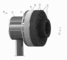
- the instrumented gripper assembly in accordance with an embodiment is shown in Figure 1 .
- the gripper assembly 10 includes a vacuum generation head 12, a plenum block 14, a check valve plate 16, a screen plate 18 and sealing foam 20 having gripping surfaces 22.
- the sealing foam includes two sets of apertures, one set that is generally centrally located with respect to the other set as further shown in Figures 6 and 7 .
- the vacuum generation and control is provided by moving compressed air through a control valve to a Venturi pump, which creates a vacuum for the gripper to distribute to the gripping surface.
- a second valve on the output of the Venturi pump allows one to blow-off acquired objects, as described above.
- the plenum block is provided below the Venturi pump, and the plenum block distributes the generated vacuum to each of the individual ports in series by means of a channels that are machined into the block. This approach minimizes the vacuum pressure required to check any individual port's control valve.
- the check valve plate consists of a number of chambers, each having a straight opening 30 at the bottom and a chamfered opening 32 at the top.
- a single such chamber (supply conduit) 34 is shown in detail in Figure 2 , together with a supply conduit plug (ball) 36 and the opening to the vacuum plenum block 32, and a pressure sensor 38.
- the pressure sensor 38 is responsive to the pressure within the chamber 34 and provides a signal to a printed circuit board 40 in the check valve plate 16.
- the screen plate 18 includes a plurality of screen openings in communication with chamber 34.
- Each of the openings 30 and chambers 34 align with and are associated with a unique aperture in the sealing foam gripper 20, and each check valve assembly (including the chamber 34, opening 32, conduit plug 36 and pressure sensor 38) functions independent of the other check valve assemblies.
- the top opening 32 mates to the plenum, thus providing a vacuum to the check valve chamber 34.
- the bottom opening 30 delivers the vacuum through the screen plate 18 to the bottom surface of the gripper 20, and thence to the object being acquired.
- the plug 36 in each check valve chamber is a plastic ball, of such a size and weight that if the bottom opening is open to atmosphere (i.e., not making contact with an object to be acquired) and a vacuum is applied to the top opening, the plastic ball 36 will be pulled by the vacuum up to the top opening, where it will seat firmly against the chamfer there and effectively seal that particular check valve port.
- the screen plate 18 mounts to the bottom of the check valve plate 16. It consists of a thin metal piece with openings that mate to each check valve. These openings are of such a size and shape (trefoil shape is used here) as to allow the ball 36 to sit on the opening without falling out, and without sealing the lower opening 30. In this way, when the port is not making contact with an object to be acquired, air will flow through this opening, lifting the ball to the top of the chamber and sealing off that particular port. When the port is making contact with an object, the vacuum will be present in the chamber 34 and will hold the object against the surface 22 of the gripper 20.
- the check valve plate is split into two pieces, top and bottom as shown in Figure 2 , and the printed circuit board 40 is sandwiched between these two halves.
- On the printed circuit board 40 is mounted an array of MEMS barometers, each of which is provided as a pressure sensor 38 for a port (again, a single port is shown in Figure 2 ). These sensors (MEMS barometers) are placed such that they are able to detect the air pressure in the bottom of the valve chamber near the gripper surface.
- Other openings 30 in the gripper 20 are associated with other valve assemblies (including other chambers, openings, conduit plugs and pressure sensors).
- the gripper is circular at the gripping surface, as shown in Figures 4 and 5 .
- This shape and symmetry provide another degree of freedom to the software control system.
- the gripping surface 22 consists of an array of ports, each of which has an integrated check valve and pressure sensor as described above.
- the gripping surface is comprised of two sections, a radially inner section 50 and a radially outer section 52. The sections are separated by a foam ring 54, which encloses the central grouping of apertures 58 and extends beyond the rest of the gripping surface.
- the second piece of foam fits around the outside of the first foam ring and extends to the outer edge of the gripper surface. It contains individual apertures 30 for each vacuum port.
- the effect of this arrangement is a hybrid modality gripper combining the benefits of the single-large-port (or "bag") configuration and the array-of-controlled-ports configuration.
- the ports 58 in the middle are all commonly open to each other within the foam ring, so that they can achieve the suction strength of a single large port while still being controlled with check valves.
- the foam ring is smaller and extends further than the rest of the gripping surface; this essentially acts as a secondary smaller gripper, allowing this device to access and acquire smaller object surfaces where the larger gripper could not otherwise fit. For larger items, simply pushing the entire device down to compress the foam ring will present the entire gripping surface to the object, allowing for compliant lifting of large objects with non-uniform surfaces.
- Figures 6 and 7 show the portion of the check valve plate that provides that multiple ports in the gripper may be commonly in communication with a single vacuum source.
- the central portion of the check valve plate includes a chamber 70 having straight openings 58 at the bottom and a chamfered opening 72 at the top.
- a single such chamber (supply conduit) 70 is shown in detail in Figure 6 , together with a supply conduit plug (ball) 76 and the opening to the vacuum plenum block 72, and a pressure sensor 74.
- the pressure sensor 74 is responsive to the pressure within the chamber 70 and provides a signal to the printed circuit board 40 in the check valve plate 16.
- the screen plate 18 includes screen openings aligned with chamber 70. Each of the openings 58 are in communication with the chamber 70.
- the top opening 72 mates to the plenum, thus providing a vacuum to the check valve chamber 70.
- the bottom openings 58 deliver the vacuum through the screen plate 18 to the bottom surface of the gripper 20 in the inner area 50 as a common group of apertures, and thence to the object being acquired.
- the plug 76 in the check valve chamber is a plastic ball, of such a size and weight that if the bottom opening is open to atmosphere (i.e., not making contact with an object to be acquired) and a vacuum is applied to the top opening, the plastic ball 76 will be pulled by the vacuum up to the top opening, where it will seat firmly against the chamfer there and effectively seal that particular check valve port as shown in Figure 6 .
- any ports that are not actually making contact with an object to be acquired are sealed and not bleeding off vacuum pressure.
- air will flow through this opening, lifting the ball to the top of the chamber and sealing off that particular port.
- the ball 76 will drop (as shown in Figure 7 ) and the vacuum will be present in the chamber 70 and will hold the object against the surface of the gripper 20 in the inner area 50.
- This hybrid modality allows for successful acquisition of a much broader spectrum of objects than either prior type of vacuum gripper by itself.
- Heavy objects in plastic bags e.g., a bag of oranges
- the central port grouping on the novel gripper presented here can acquire these objects.
- Another example is a bottle of shampoo standing upright; a typical single large port type gripper will be too large to seal to the top of the cap, and thus will not acquire the object.
- the novel gripper here can use a single port from the outer ring to seal to the shampoo cap; all other ports, including the central group, will check, allowing this device to successfully acquire the object.
- different vacuum pressures may be applied to the inner set of apertures as compared to the outer set of apertures in a variety of ways, including for example, restricting air flow in the outer set of apertures.
- the invention further provides a system for providing high flow vacuum control to an end effector of an articulated arm.
- the invention provides a dynamic high flow gripping system, and may optionally include a mechanism to select between the high flow source and a high vacuum source, depending on the application. High flow vacuum systems of the invention may therefore optionally be used with high vacuum sources.
- the system may include a first vacuum source for providing a first vacuum pressure with a first maximum air flow rate (to for example, the inner area 50), and a second vacuum source for providing a second vacuum pressure with a second maximum air flow rate (to for example, the outer area 52).
- the second vacuum pressure is higher than the first vacuum pressure and wherein the second maximum air flow rate is greater than the first maximum air flow rate.
- the flow rates are characterized as maximum air flow rates because, when an object is engaged at an end effector, the flow rate may drop significantly.
- the high flow source may be used together with a high vacuum source, or as a single source.
- Figure 8 shows a system 100 for use with an end effector in accordance with an embodiment of the present invention in which an optional high vacuum source 102 is provided as well as a high flow source 104 and a release source 106 that are each coupled to a selection unit 108, that is coupled to an end effector 110.
- the selection unit 108 selects between the high vacuum source 102, high flow source 104 and the release source 106 for providing any of high vacuum, vacuum with high flow, or a release flow to the end effector.
- Figure 8 therefore shows a general form of the invention, comprising mechanisms for producing high vacuum and high flow, a release source providing either atmospheric pressure via a vent or high pressure (blow off) via a compressor or reservoir, and a mechanism for selecting the source best suited to the present situation.
- Figure 9 shows a system 120 in accordance with an embodiment of the invention that includes a compressor 122 that is coupled to an ejector 124 to provide a high vacuum source that is coupled to a solenoid valve 126.
- a blower 128 is also coupled to the solenoid valve 120 via a non-return valve 130, and the blower 128 provides a vacuum source with a high maximum flow rate.
- a vent or blow-off source is also provided to the solenoid valve 120, the output of which is provided to an end effector 132.
- the system therefore, provides the ejector 124 as the high vacuum source, the regenerative blower 128 as the high flow source, the non-return valve 130 as a passive selection mechanism, and the solenoid valve 120 connecting the effector to the release source, either vent or blow-off.
- the vacuum pressure provided by the ejector 124 may be, for example, at least about 90,000 Pascals below atmospheric and the vacuum pressure provided by the blower 128 may be only no more than about 25,000 Pascals below atmospheric in some examples, and no more than about 50,000 Pascals below atmospheric in other examples.
- the vacuum pressure provided by the blower 128 is therefore higher than the vacuum pressure provided by the ejector 124.
- the maximum air flow rate of the ejector may be, for example, no more than about 5 cubic feet per minute (e.g., 1 - 2 cubic feet per minute), and the maximum air flow rate of the blower may be, for example at least about 100 cubic feet per minute (e.g., 130 - 140 cubic feet per minute).
- end effectors of the invention may include a central region of a gripper surface that provides high flow gripping.
- the surface at the central region of the gripper may include a specialized opening cover for use with a high flow vacuum gripper.
- a cover 140 may include a proximal back side 142 that does not permit air to flow through the material, and distal front side 144 for engaging objects that is formed of a foam material.
- Slit openings 146 in form of a star or asterisk shape are provided through the material in this example.
- the compliant foam on the surface 144 contacts the object to be acquired, giving the gripper some compliance while also acting to seal the aperture around the object as the foam is compressed and the high flow vacuum is applied.
- the aperture cover therefore allows a high flow gripper to effectively pick up long narrow objects with an easy to attach cover that may be held in a tool changer and added or removed from the gripper autonomously during real-time operation
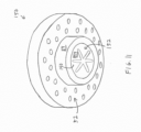
- Figure 11 shows an end effector gripper 150 having such a cover 140 used in connection with a gripper surface having an outer section 52 as discussed above, and an inner section 152 providing high flow through the cover 140.
- the cover may also be flush with the circular wall 54 as shown.
- a system for providing vacuum control to an end effector of an articulated arm, where the system includes a vacuum source for providing a vacuum pressure at a flow rate to the end effector, and the end effector includes a cover that includes an opening that varies significantly in radius from a center of the cover.
- the opening may include finger openings that extend radially from the center of the opening.
- the opening may be generally star shaped or asterisk shaped.
- the cover may include compliant foam on a distal side of the cover that engages an object to be grasped, and an air flow resistant material on a proximal side of the cover.
- the vacuum pressure may be no more than about 50,000 Pascals below atmospheric, and the air flow rate may be at least about 100 cubic feet per minute.
- the invention therefore provides a system for providing vacuum control to an end effector of an articulated arm, where the system includes a vacuum source for providing a vacuum pressure at a flow rate to the end effector, and the end effector includes a cover including an air flow resistant material on a proximal side of the cover and a compliant material on a distal side of the cover for contacting objects to be grasped.
- the cover may include an opening that varies significantly in radius from a center of the cover, and the opening may include finger openings that extend radially from the center of the opening.
- the opening may be generally star shaped or asterisk shaped.
- the cover may be formed of a compliant material and include compliant foam on a distal side of the cover that engages an object to be grasped, and the cover may include an air flow resistant material on a proximal side of the cover.
- the vacuum pressure may be no more than about 25,000 Pascals or 50,000 Pascals below atmospheric, and the air flow rate may be at least about 100 cubic feet per minute.
- FIG. 12A shows a cover 160 that includes slit openings 162.
- Figure 12B shows a cover 170 that includes different sized square openings 172, 174.
- Cover 180 shown in Figure 12C includes small circular openings 182, and cover 190 shown in Figure 12D includes differently shaped openings 192 and 194.
- a compliant foam surface may face the object to be acquired, and more area of the cover is provided to be open closer to the center of the cover with respect to the outer periphery of each cover. For example, in the cover 140, the center of the asterisks shape is most open.
- the larger slits are provided in the center.
- the larger square openings are provided in the center.
- the greater concentration of the circular openings is provided in the center, and in the cover 190, the lager shape 192 is provided in the center.
- the gripper assembly may be mounted to the end of a wide variety of 4- or 6-axis robotic arms.
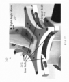
- the mounting assembly 200 incorporates load cells, as shown in Figure 13 .
- load cells 202 placed between the mounting bracket 204 at the end of the robotic arm and the top surface of the gripper body 206.
- One of these load cells is placed at each corner of the gripper body, allowing the SW system to precisely know the distribution of weight of an acquired object and the resulting forces and torques that the object is placing on the gripper.
- These sensors will also detect if an object has fallen off of the gripper during acquisition or movement; the Software system will integrate this data with the data provided by the array of pressure sensors in the check valve block to provide input to the algorithms that are maximizing abort/retry efficiency and speed.
- the system therefore, does not require the use of sophisticated software algorithms that use probabilistic and predictive processes to maximize speed and efficiency of acquisition / failure / abort / retry cycles with multi-fingered hand-type grasping end effectors.
- These algorithms rely on precise data about joint angles and motor speeds / currents / torques as well as image data from 2D or 3D camera systems to know whether or not an acquisition has been successful and plan a retry if necessary. Because vacuum grippers have previously lacked any type of similarly sophisticated sensing, and because previous applications have been limited and highly controlled, these algorithms have not been applied previously to vacuum gripping situations.
- the novel gripper described here provides such data using inexpensive sensors (load cells and MEMS barometers).
- load cells and MEMS barometers When the gripper is placed on an object and the vacuum is enabled, the software control system will immediately have a map of which ports are providing suction to the object and which are checked closed. With a priori knowledge of the object (from 2D/3D imaging and database matching, for instance), the SW will be able to calculate a success percentage for object acquisition.
- control system can shut off vacuum and reposition the gripper to try again quickly without having to actually attempt and fail at acquisition first. This will greatly enhance retry speed.
- the control system can raise the gripper. At this point, the data from the load cell array will begin to tell the control system whether or not the object weight is being lifted, and at what position and torque. As the object is being moved, the load cell and port pressure data will also warn the control system if the acquisition is failing and the object is going to fall, allowing the control system to take appropriate action.
- This data will provide the software control system a real time picture of where, how, and how well an object is acquired, from before the gripper has even been moved all the way through object delivery and release.
- This data can be used by a software control system as input for efficient abort / retry algorithms previously only used by more sophisticated manipulators.
- the instrumented hybrid-modality vacuum gripper presented here therefore, combines the benefits of prior vacuum gripper configurations into a single device, at the same time integrating sensors that provide the kind of detailed acquisition data needed to enable advanced abort/retry efficiency software algorithms previously reserved for more sophisticated multi-finger type grippers.
- the result is a single inexpensive end effector that can be used to rapidly and efficiently acquire and move a very broad spectrum of object types, sizes, weights, and packaging types, in a variety of orientations.
Landscapes
- Engineering & Computer Science (AREA)
- Mechanical Engineering (AREA)
- Robotics (AREA)
- Chemical & Material Sciences (AREA)
- Dispersion Chemistry (AREA)
- Manipulator (AREA)
- Lift Valve (AREA)
Applications Claiming Priority (3)
| Application Number | Priority Date | Filing Date | Title |
|---|---|---|---|
| US201562210246P | 2015-08-26 | 2015-08-26 | |
| PCT/US2016/048968 WO2017035466A1 (en) | 2015-08-26 | 2016-08-26 | Systems and methods for providing vacuum valve assemblies for end effectors |
| EP16763400.5A EP3341166B1 (de) | 2015-08-26 | 2016-08-26 | Systeme und verfahren zur bereitstellung von vakuumventilanordnungen für endeffektoren |
Related Parent Applications (1)
| Application Number | Title | Priority Date | Filing Date |
|---|---|---|---|
| EP16763400.5A Division EP3341166B1 (de) | 2015-08-26 | 2016-08-26 | Systeme und verfahren zur bereitstellung von vakuumventilanordnungen für endeffektoren |
Publications (2)
| Publication Number | Publication Date |
|---|---|
| EP4219096A1 true EP4219096A1 (de) | 2023-08-02 |
| EP4219096B1 EP4219096B1 (de) | 2025-03-26 |
Family
ID=56894283
Family Applications (2)
| Application Number | Title | Priority Date | Filing Date |
|---|---|---|---|
| EP16763400.5A Active EP3341166B1 (de) | 2015-08-26 | 2016-08-26 | Systeme und verfahren zur bereitstellung von vakuumventilanordnungen für endeffektoren |
| EP23166963.1A Active EP4219096B1 (de) | 2015-08-26 | 2016-08-26 | Systeme und verfahren zur bereitstellung von vakuumventilanordnungen für endeffektoren |
Family Applications Before (1)
| Application Number | Title | Priority Date | Filing Date |
|---|---|---|---|
| EP16763400.5A Active EP3341166B1 (de) | 2015-08-26 | 2016-08-26 | Systeme und verfahren zur bereitstellung von vakuumventilanordnungen für endeffektoren |
Country Status (6)
| Country | Link |
|---|---|
| US (6) | US9999977B2 (de) |
| EP (2) | EP3341166B1 (de) |
| CN (2) | CN113601545B (de) |
| CA (2) | CA2996868C (de) |
| ES (2) | ES3033211T3 (de) |
| WO (1) | WO2017035466A1 (de) |
Families Citing this family (54)
| Publication number | Priority date | Publication date | Assignee | Title |
|---|---|---|---|---|
| WO2017035466A1 (en) * | 2015-08-26 | 2017-03-02 | Berkshire Grey Inc. | Systems and methods for providing vacuum valve assemblies for end effectors |
| CA2996698C (en) | 2015-08-26 | 2021-07-13 | Berkshire Grey, Inc. | Systems and methods for providing contact detection in an articulated arm |
| ES2935283T3 (es) | 2015-09-01 | 2023-03-03 | Berkshire Grey Operating Company Inc | Sistemas y métodos para proporcionar sistemas de control robótico dinámico |
| US11370128B2 (en) | 2015-09-01 | 2022-06-28 | Berkshire Grey Operating Company, Inc. | Systems and methods for providing dynamic robotic control systems |
| CA2998128C (en) | 2015-09-08 | 2023-11-28 | Berkshire Grey, Inc. | Systems and methods for providing high flow vacuum acquisition in automated systems |
| ES2922990T3 (es) | 2016-01-08 | 2022-09-22 | Berkshire Grey Operating Company Inc | Sistemas de adquisición y movimiento de objetos |
| CN108778636B (zh) | 2016-02-08 | 2021-11-19 | 伯克希尔格雷股份有限公司 | 用于提供使用运动规划的各种物体的处理的系统和方法 |
| CA3045522C (en) | 2016-12-06 | 2023-10-03 | Berkshire Grey, Inc. | Systems and methods for providing for the processing of objects in vehicles |
| CN115319788A (zh) | 2017-03-06 | 2022-11-11 | 伯克希尔格雷运营股份有限公司 | 用于有效地移动各种物体的系统和方法 |
| ES2982906T3 (es) | 2017-03-22 | 2024-10-18 | Berkshire Grey Operating Company Inc | Sistemas y métodos para procesar objetos, incluyendo estaciones de procesamiento radial automatizadas |
| US10941000B2 (en) | 2017-03-23 | 2021-03-09 | Berkshire Grey, Inc. | Systems and methods for processing objects, including automated linear processing stations |
| US11205059B2 (en) | 2017-04-18 | 2021-12-21 | Berkshire Grey, Inc. | Systems and methods for separating objects using conveyor transfer with one or more object processing systems |
| US11416695B2 (en) | 2017-04-18 | 2022-08-16 | Berkshire Grey Operating Company, Inc. | Systems and methods for distributing induction of objects to a plurality of object processing systems |
| EP3612472A1 (de) | 2017-04-18 | 2020-02-26 | Berkshire Grey, Inc. | Systeme und verfahren zur verarbeitung von objekten; einschliesslich raumeffizienten verteilungsstationen und automatisierter ausgangsverarbeitung |
| US11055504B2 (en) | 2017-04-18 | 2021-07-06 | Berkshire Grey, Inc. | Systems and methods for separating objects using a vacuum roller with one or more object processing systems |
| US11080496B2 (en) | 2017-04-18 | 2021-08-03 | Berkshire Grey, Inc. | Systems and methods for separating objects using vacuum diverts with one or more object processing systems |
| US11373134B2 (en) | 2018-10-23 | 2022-06-28 | Berkshire Grey Operating Company, Inc. | Systems and methods for dynamic processing of objects with data verification |
| US11200390B2 (en) | 2017-04-18 | 2021-12-14 | Berkshire Grey, Inc. | Systems and methods for separating objects using drop conveyors with one or more object processing systems |
| US11301654B2 (en) | 2017-04-18 | 2022-04-12 | Berkshire Grey Operating Company, Inc. | Systems and methods for limiting induction of objects to one or more object processing systems |
| CN107009382A (zh) * | 2017-06-09 | 2017-08-04 | 成都众智优学教育咨询有限公司 | 基于流体力学的吸附式取料手 |
| ES2973662T3 (es) | 2017-08-02 | 2024-06-21 | Berkshire Grey Operating Company Inc | Sistemas y procedimientos de adquisición y desplazamiento de objetos con superficies exteriores complejas |
| US11254013B2 (en) * | 2017-10-11 | 2022-02-22 | Softbox Patents Aps | Interchangeable robot gripper base |
| CA3080961C (en) * | 2017-11-07 | 2023-10-03 | Berkshire Grey, Inc. | Systems and methods for providing dynamic vacuum pressure at an end effector using a single vacuum source |
| WO2019143710A1 (en) | 2018-01-17 | 2019-07-25 | Berkshire Grey, Inc. | Systems and methods for efficiently moving a variety of objects |
| CA3107825C (en) | 2018-07-27 | 2023-06-13 | Berkshire Grey, Inc. | Systems and methods for efficiently exchanging end effector tools |
| CN109227591A (zh) * | 2018-09-14 | 2019-01-18 | 合肥安信瑞德精密制造有限公司 | 一种手持式便于抓取阀片的工具 |
| EP3908991A1 (de) * | 2019-01-08 | 2021-11-17 | Berkshire Grey, Inc. | Systeme und verfahren zum trennen von objekten mittels vakuumwalze mit einer oder mehreren objektverarbeitungssystemen |
| EP3969400A4 (de) * | 2019-05-16 | 2023-06-14 | Core Flow Ltd. | Sauggreifer für verzerrtes werkstück |
| US11724880B2 (en) | 2019-07-29 | 2023-08-15 | Nimble Robotics, Inc. | Storage systems and methods for robotic picking |
| US11738447B2 (en) | 2019-07-29 | 2023-08-29 | Nimble Robotics, Inc. | Storage systems and methods for robotic picking |
| WO2021026183A1 (en) | 2019-08-08 | 2021-02-11 | Berkshire Grey, Inc. | Systems and methods for providing, in programmable motion devices, compliant end effectors with noise mitigation |
| CA3170700A1 (en) | 2020-02-05 | 2021-08-12 | Berkshire Grey Operating Company, Inc. | End-effector, programmable motion device and method of operating a programmable motion device |
| EP4135943A4 (de) | 2020-04-17 | 2024-05-29 | Muth Mirror Systems, LLC | Sicherungsgerät und verfahren zur verwendung |
| CN111438706A (zh) * | 2020-04-30 | 2020-07-24 | 苏州光韵达光电科技有限公司 | 一种用于上下料机的真空吸盘 |
| CN111674920A (zh) * | 2020-06-05 | 2020-09-18 | 杭州展雄智能装备有限公司 | 一种可止回的真空吸具及其制作方法 |
| CN116133805A (zh) | 2020-07-22 | 2023-05-16 | 伯克希尔格雷营业股份有限公司 | 用于使用通过护罩反转提供对象保持的真空夹持器进行对象处理的系统和方法 |
| EP4185445A1 (de) | 2020-07-22 | 2023-05-31 | Berkshire Grey Operating Company, Inc. | Systeme und verfahren zur objektverarbeitung mit einem passiv klappbaren vakuumgreifer |
| CN114310863A (zh) * | 2020-09-29 | 2022-04-12 | 艾卡(南通)智能科技有限公司 | 一种模块化机器人执行工具 |
| EP4247599B1 (de) | 2020-11-19 | 2025-08-20 | Berkshire Grey Operating Company, Inc. | Systeme und verfahren zur objektverarbeitung unter verwendung von greifern für objekte mit niedriger haltungsautorität |
| US11932129B2 (en) | 2020-12-21 | 2024-03-19 | Nimble Robotics, Inc. | Mobile robot having pneumatic charging system |
| US20220193918A1 (en) * | 2020-12-21 | 2022-06-23 | All Weigh Automation LLC | Robotically manipulated container gripper and related systems and methods |
| EP4019210A1 (de) * | 2020-12-24 | 2022-06-29 | Aerosol d.o.o. | Sauggreifer zur automatischen manipulation von filtern und mit dem besagten greifer zu verwendende filterkammer |
| US12304062B2 (en) * | 2021-01-04 | 2025-05-20 | The Boeing Company | Part transfer system |
| FR3122597B1 (fr) * | 2021-05-10 | 2023-10-13 | Safran Nacelles | Tête de préhension, notamment pour l’application d’un patch sur une surface à draper |
| JP2025502285A (ja) * | 2022-01-18 | 2025-01-24 | ピアブ アクチエボラグ | 真空グリッパ、グリッパへの漏れを検知する方法ならびにグリッパを使用した自動化されたプロセスおよびその使用 |
| US12447605B2 (en) | 2022-01-21 | 2025-10-21 | Berkshire Grey Operating Company, Inc. | Systems and methods for object processing with programmable motion devices using yawing grippers |
| US20230238256A1 (en) * | 2022-01-27 | 2023-07-27 | Changxin Memory Technologies, Inc. | Apparatus for processing wafer and method for controlling processing of wafer |
| CN118984802A (zh) | 2022-03-23 | 2024-11-19 | 伯克希尔格雷营业股份有限公司 | 用于动态处理物体的缓冲系统和方法 |
| CN114670251A (zh) * | 2022-04-25 | 2022-06-28 | 北京京东乾石科技有限公司 | 称重传感器组件、端拾器、机械手和机器人 |
| JP2024083701A (ja) * | 2022-12-12 | 2024-06-24 | Smc株式会社 | 吸着パッド |
| EP4633882A1 (de) * | 2022-12-20 | 2025-10-22 | Nexera Robotics Corporation | System und verfahren zur steuerung einer intelligenten greifvorrichtung |
| FR3149533A1 (fr) * | 2023-06-08 | 2024-12-13 | Exotec | Préhenseur pneumatique robotisé, procédé de préhension et circuit pneumatique |
| CN117657771A (zh) * | 2023-12-22 | 2024-03-08 | 苏州派迅智能科技有限公司 | 一种兼容多规格存储单元的海绵吸盘 |
| EP4663356A1 (de) * | 2024-06-10 | 2025-12-17 | Gaiotto Automation S.p.A. | Steuerungsverfahren zur steuerung eines artikelhandhabungssystems |
Citations (4)
| Publication number | Priority date | Publication date | Assignee | Title |
|---|---|---|---|---|
| EP1671906A1 (de) * | 2004-12-20 | 2006-06-21 | Giacobbe Mazzucchelli | Unterdruckventil zur Verwendung in einer Greifervorrichtung für Platten |
| EP2014587A2 (de) * | 2007-06-07 | 2009-01-14 | CO-MATIC S.a.s. di Cavallari Ivan & C. | Vakuumbasierte Elementhaltevorrichtung |
| US20130277999A1 (en) * | 2012-04-20 | 2013-10-24 | Varian Semiconductor Equipment Associates, Inc. | Venturi assisted gripper |
| WO2017044627A1 (en) * | 2015-09-08 | 2017-03-16 | Berkshire Grey Inc. | Systems and methods for providing dynamic vacuum pressure in an articulated arm end effector |
Family Cites Families (70)
| Publication number | Priority date | Publication date | Assignee | Title |
|---|---|---|---|---|
| US2653333A (en) | 1949-06-03 | 1953-09-29 | Brysman Moissey | Window-washing machine |
| US2853333A (en) | 1955-09-07 | 1958-09-23 | Littell Machine Co F J | Vacuum cup |
| US3005652A (en) | 1960-12-14 | 1961-10-24 | Bemis Bro Bag Co | Vacuum gripping device |
| US3195941A (en) | 1962-08-27 | 1965-07-20 | Whiting Corp | Vacuum gripping pad |
| US3637249A (en) | 1970-06-29 | 1972-01-25 | Henry Y Kuhl | Automatic loader heads |
| FR2495592A1 (fr) | 1980-12-05 | 1982-06-11 | Joulin Sema | Dispositif de prehension fonctionnant par succion |
| US4412775A (en) | 1982-03-10 | 1983-11-01 | Multifold-International, Inc. | Vacuum assisted machine for handling articles |
| US4495968A (en) | 1982-07-16 | 1985-01-29 | Combined Fluid Products Company | Pneumatic control system |
| US4557659A (en) | 1982-09-14 | 1985-12-10 | M. Scaglia S.P.A. | Device for supporting and handling loads by means of vacuum operated suction pads |
| JPS6155399A (ja) | 1984-08-27 | 1986-03-19 | Shoketsu Kinzoku Kogyo Co Ltd | 真空発生装置 |
| DE3810989A1 (de) * | 1988-02-01 | 1989-08-10 | Festo Kg | Vorrichtung zur handhabung und insbesondere zum transport von gegenstaenden |
| US4880358A (en) | 1988-06-20 | 1989-11-14 | Air-Vac Engineering Company, Inc. | Ultra-high vacuum force, low air consumption pumps |
| US5024575A (en) | 1989-09-08 | 1991-06-18 | Robotic Originals, Inc. | Lightweight gripper for robotic transfer operations |
| JP2601114B2 (ja) | 1992-11-19 | 1997-04-16 | コクヨ株式会社 | 電動穿孔機における穿孔屑の落下止め装置 |
| JPH0769470A (ja) | 1993-06-30 | 1995-03-14 | Morihiko Mizumura | シート部材の取上げ装置 |
| WO1995012541A1 (en) | 1993-11-04 | 1995-05-11 | Comalco Aluminium Limited | Vacuum lifting device |
| US5865487A (en) | 1996-05-23 | 1999-02-02 | Motorola, Inc. | Pick-and-place tool for vacuum and magnetic coupling |
| US5890553A (en) * | 1996-08-01 | 1999-04-06 | California Institute Of Technology | Multifunction automated crawling system |
| DE19817426B4 (de) | 1998-04-18 | 2004-06-09 | J. Schmalz Gmbh | Greifersystem, insbesondere Vakuumgreifersystem |
| US6015174A (en) | 1998-06-04 | 2000-01-18 | Eastman Kodak Company | Universal end effector for robotic applications |
| FR2782313B1 (fr) | 1998-08-13 | 2000-11-24 | Opema | Dispositif de prehension |
| CN1367729A (zh) * | 1999-09-08 | 2002-09-04 | 元利盛精密机械股份有限公司 | 吸嘴以及电子器件装配装置 |
| US6276478B1 (en) * | 2000-02-16 | 2001-08-21 | Kathleen Garrubba Hopkins | Adherent robot |
| DE10009108A1 (de) | 2000-02-26 | 2001-09-06 | Schmalz J Gmbh | Vakuumhandhabungsgerät |
| DE10033212C1 (de) | 2000-07-07 | 2002-01-24 | Festo Ag & Co | Vakuumerzeugervorrichtung |
| US6397876B1 (en) | 2001-02-06 | 2002-06-04 | Norgren Automotive, Inc. | Method for maintaining the operating condition of a vacuum responsive device during loss and resumption of power |
| DE10121344A1 (de) | 2001-05-02 | 2002-11-07 | Fft Flexible Fertigungstechnik | Zum Greifen von Gegenständen ausgebildete Greifvorrichtung |
| DE10140248B4 (de) | 2001-08-09 | 2006-09-28 | J. Schmalz Gmbh | Unterdruckhandhabungseinrichtung |
| US7155307B2 (en) * | 2001-09-09 | 2006-12-26 | Seemann Henry R | Surface adhering tool carrying robot |
| JP4132897B2 (ja) | 2002-03-19 | 2008-08-13 | 株式会社日本ピスコ | 真空発生装置 |
| JP2004351527A (ja) * | 2003-05-27 | 2004-12-16 | Koganei Corp | 吸着検出方法および吸着検出装置 |
| DE102004042825B3 (de) * | 2004-08-28 | 2006-01-05 | J. Schmalz Gmbh | Verfahren zum Betreiben einer Unterdruckhandhabungseinrichtung |
| DE102004057775B4 (de) | 2004-11-30 | 2007-05-10 | Multitest Elektronische Systeme Gmbh | Handhabungsvorrichtung zum Zuführen von elektronischen Bauelementen, insbesondere IC's, zu einer Testvorrichtung |
| US7481472B2 (en) | 2005-03-15 | 2009-01-27 | Sage Automation, Inc. | Layer picking end effector system, apparatus and method |
| DE102005045681B4 (de) * | 2005-09-24 | 2007-07-26 | Eckelt Glas Gmbh | Verfahren zum Steuern von Unterdruck-Hebezeugen und Lastsicherungsvorrichtung für Unterdruck-Hebezeuge sowie deren Verwendung |
| US7409812B2 (en) | 2006-06-29 | 2008-08-12 | Smart Motion Robotics, Inc. | Robotic packaging device and method |
| JP4582484B2 (ja) | 2006-12-20 | 2010-11-17 | Smc株式会社 | 真空吸着装置 |
| SE530787C2 (sv) | 2007-01-16 | 2008-09-09 | Xerex Ab | Ejektoranordning med luftningsfunktion |
| US7819235B2 (en) | 2007-01-29 | 2010-10-26 | Electro Scientific Industries, Inc. | Venturi vacuum generator on an electric component handler |
| ES2387521T3 (es) | 2007-04-25 | 2012-09-25 | Delaware Capital Formation, Inc. | Sistema y método de manipulación de materiales |
| JP2008302487A (ja) * | 2007-06-11 | 2008-12-18 | Olympus Corp | 基板吸着装置及び基板搬送装置並びに外観検査装置 |
| DE202007009414U1 (de) * | 2007-07-04 | 2008-11-13 | pfm Produkte für die Medizin AG | Vorevakuierbarer oder vorevakuierter Behälter für medizinische Zwecke |
| DE102007054867A1 (de) | 2007-11-07 | 2009-05-20 | J. Schmalz Gmbh | Greifvorrichtung |
| DE202008010424U1 (de) * | 2008-07-30 | 2009-12-24 | J. Schmalz Gmbh | Mit Druckluft betriebener Flächensauggreifer |
| JP4708464B2 (ja) | 2008-09-30 | 2011-06-22 | ファナック株式会社 | ワーク把持装置 |
| JP5163541B2 (ja) | 2009-03-02 | 2013-03-13 | 三菱マテリアルテクノ株式会社 | 真空吸着パッド |
| US20110293397A1 (en) | 2010-05-25 | 2011-12-01 | Lomerson Jr Roland | End Effector for Picking, Forming, and Inserting U-Shaped Packing Insert |
| DE102011006679B4 (de) | 2011-03-16 | 2018-07-12 | Ferrobotics Compliant Robot Technology Gmbh | Aktive Handhabungsvorrichtung und Verfahren für Kontaktaufgaben |
| DE102011115951B4 (de) | 2011-10-13 | 2016-03-31 | BIBA - Bremer Institut für Produktion und Logistik GmbH | Greifwerkzeug zur Förderung von unregelmäßig angeordneten Gütern, Greifersystem mit demselben sowie Verfahren zum Abfördern |
| US8960745B2 (en) | 2011-11-18 | 2015-02-24 | Nike, Inc | Zoned activation manufacturing vacuum tool |
| US9061868B1 (en) | 2012-07-19 | 2015-06-23 | Wepco., Inc. | Vacuum-assisted carton or box lifter |
| EP2708335A1 (de) | 2012-09-14 | 2014-03-19 | Knapp AG | Hochgeschwindigkeits-Greiferwechselsystem |
| EP2935058A1 (de) | 2012-12-21 | 2015-10-28 | Short Brothers Plc | Saugnapf |
| EP2981492B1 (de) | 2013-04-02 | 2017-08-16 | Inva Invest Holding ApS | Strömungssperrventil, vakuumhebevorrichtung und verfahren zum betreiben einer vakuumhebevorrichtung |
| SG2013069893A (en) | 2013-09-13 | 2015-04-29 | Jcs Echigo Pte Ltd | Material handling system and method |
| CN203680306U (zh) * | 2013-12-20 | 2014-07-02 | 君帆工业股份有限公司 | 非接触式多孔真空浮吸器 |
| US9669550B2 (en) | 2014-04-18 | 2017-06-06 | Kla-Tencor Corporation | Pick and place device with automatic pick-up-height adjustment and a method and a computer program product to automatically adjust the pick-up-height of a pick and place device |
| FR3020303B1 (fr) | 2014-04-25 | 2016-07-15 | Sileane | Procede et installation de prehension automatique d'un objet. |
| ES2845927T3 (es) | 2014-06-26 | 2021-07-28 | Schmalz J Gmbh | Instalación para la manipulación de piezas de trabajo |
| CN104181723B (zh) * | 2014-08-26 | 2018-03-06 | 深圳市华星光电技术有限公司 | 平板玻璃用对组系统及对组方法 |
| US10001245B2 (en) * | 2014-12-08 | 2018-06-19 | The Boeing Company | Apparatus and method for coupling an end effector to a structure |
| FR3032364B1 (fr) | 2015-02-11 | 2017-01-27 | Solystic | Installation pour la separation et l'individualisation d'objets postaux heterogenes avec un systeme de vision a sources laser |
| DE102015202603A1 (de) | 2015-02-12 | 2016-08-18 | J. Schmalz Gmbh | Unterdruckerzeugervorrichtung und Schlauchheber mit einer Unterdruckerzeugervorrichtung |
| WO2017035466A1 (en) * | 2015-08-26 | 2017-03-02 | Berkshire Grey Inc. | Systems and methods for providing vacuum valve assemblies for end effectors |
| CA2996698C (en) | 2015-08-26 | 2021-07-13 | Berkshire Grey, Inc. | Systems and methods for providing contact detection in an articulated arm |
| ES2935283T3 (es) | 2015-09-01 | 2023-03-03 | Berkshire Grey Operating Company Inc | Sistemas y métodos para proporcionar sistemas de control robótico dinámico |
| ES2976182T3 (es) | 2015-09-09 | 2024-07-26 | Berkshire Grey Operating Company Inc | Sistema y método para proporcionar una iluminación comunicativa dinámica en un entorno robótico |
| EP4235539A3 (de) | 2015-09-11 | 2023-09-27 | Berkshire Grey Operating Company, Inc. | Robotersysteme und verfahren zur identifikation und verarbeitung von verschiedenen objekten |
| WO2017083574A1 (en) | 2015-11-13 | 2017-05-18 | Berkshire Grey Inc. | Sortation systems and methods for providing sortation of a variety of obejcts |
| CN108778636B (zh) | 2016-02-08 | 2021-11-19 | 伯克希尔格雷股份有限公司 | 用于提供使用运动规划的各种物体的处理的系统和方法 |
-
2016
- 2016-08-26 WO PCT/US2016/048968 patent/WO2017035466A1/en not_active Ceased
- 2016-08-26 CN CN202110937940.3A patent/CN113601545B/zh active Active
- 2016-08-26 CA CA2996868A patent/CA2996868C/en active Active
- 2016-08-26 CN CN201680061046.1A patent/CN108136596B/zh active Active
- 2016-08-26 EP EP16763400.5A patent/EP3341166B1/de active Active
- 2016-08-26 US US15/248,379 patent/US9999977B2/en active Active
- 2016-08-26 CA CA3104707A patent/CA3104707C/en active Active
- 2016-08-26 EP EP23166963.1A patent/EP4219096B1/de active Active
- 2016-08-26 ES ES23166963T patent/ES3033211T3/es active Active
- 2016-08-26 ES ES16763400T patent/ES2948058T3/es active Active
-
2018
- 2018-04-24 US US15/961,275 patent/US10300612B2/en active Active
-
2019
- 2019-04-23 US US16/391,980 patent/US10647005B2/en active Active
-
2020
- 2020-03-26 US US16/830,574 patent/US11185996B2/en active Active
-
2021
- 2021-10-19 US US17/504,977 patent/US11660763B2/en active Active
-
2023
- 2023-04-13 US US18/134,458 patent/US20230249362A1/en active Pending
Patent Citations (4)
| Publication number | Priority date | Publication date | Assignee | Title |
|---|---|---|---|---|
| EP1671906A1 (de) * | 2004-12-20 | 2006-06-21 | Giacobbe Mazzucchelli | Unterdruckventil zur Verwendung in einer Greifervorrichtung für Platten |
| EP2014587A2 (de) * | 2007-06-07 | 2009-01-14 | CO-MATIC S.a.s. di Cavallari Ivan & C. | Vakuumbasierte Elementhaltevorrichtung |
| US20130277999A1 (en) * | 2012-04-20 | 2013-10-24 | Varian Semiconductor Equipment Associates, Inc. | Venturi assisted gripper |
| WO2017044627A1 (en) * | 2015-09-08 | 2017-03-16 | Berkshire Grey Inc. | Systems and methods for providing dynamic vacuum pressure in an articulated arm end effector |
Also Published As
| Publication number | Publication date |
|---|---|
| US20170080579A1 (en) | 2017-03-23 |
| CN113601545A (zh) | 2021-11-05 |
| EP3341166A1 (de) | 2018-07-04 |
| CN108136596B (zh) | 2021-08-24 |
| US11660763B2 (en) | 2023-05-30 |
| US20200223073A1 (en) | 2020-07-16 |
| US20220055231A1 (en) | 2022-02-24 |
| CA3104707C (en) | 2022-10-18 |
| US11185996B2 (en) | 2021-11-30 |
| US9999977B2 (en) | 2018-06-19 |
| US10647005B2 (en) | 2020-05-12 |
| WO2017035466A1 (en) | 2017-03-02 |
| CN113601545B (zh) | 2024-08-30 |
| ES2948058T3 (es) | 2023-08-30 |
| ES3033211T3 (en) | 2025-07-31 |
| CA3104707A1 (en) | 2017-03-02 |
| CN108136596A (zh) | 2018-06-08 |
| EP3341166B1 (de) | 2023-04-12 |
| US10300612B2 (en) | 2019-05-28 |
| US20190248025A1 (en) | 2019-08-15 |
| US20180236670A1 (en) | 2018-08-23 |
| CA2996868A1 (en) | 2017-03-02 |
| CA2996868C (en) | 2021-02-16 |
| US20230249362A1 (en) | 2023-08-10 |
| EP4219096B1 (de) | 2025-03-26 |
Similar Documents
| Publication | Publication Date | Title |
|---|---|---|
| US11185996B2 (en) | Systems and methods for providing vacuum valve assemblies for end effectors | |
| US12304061B2 (en) | Systems and methods for providing high flow vacuum acquisition in automated systems | |
| CN113021401B (zh) | 用于夹持和保持物体的机器人多爪夹持器总成和方法 | |
| CN111993448B (zh) | 用于夹持和保持物体的机器人多夹持器组件和方法 | |
| Kessens et al. | Versatile aerial grasping using self-sealing suction | |
| WO2022090700A3 (en) | System and method for sorting and/or packing items | |
| McCulloch et al. | Towards a universal gripper–on the use of suction in the context of the amazon robotic challenge | |
| CN223990611U (zh) | 拾取装置 | |
| CN223722125U (zh) | 一种码垛机器人用视觉自适应吸盘夹具 | |
| ES2984480T3 (es) | Aparato y método para evaluación de piezas de trabajo |
Legal Events
| Date | Code | Title | Description |
|---|---|---|---|
| PUAI | Public reference made under article 153(3) epc to a published international application that has entered the european phase |
Free format text: ORIGINAL CODE: 0009012 |
|
| STAA | Information on the status of an ep patent application or granted ep patent |
Free format text: STATUS: THE APPLICATION HAS BEEN PUBLISHED |
|
| AC | Divisional application: reference to earlier application |
Ref document number: 3341166 Country of ref document: EP Kind code of ref document: P |
|
| AK | Designated contracting states |
Kind code of ref document: A1 Designated state(s): AL AT BE BG CH CY CZ DE DK EE ES FI FR GB GR HR HU IE IS IT LI LT LU LV MC MK MT NL NO PL PT RO RS SE SI SK SM TR |
|
| STAA | Information on the status of an ep patent application or granted ep patent |
Free format text: STATUS: REQUEST FOR EXAMINATION WAS MADE |
|
| 17P | Request for examination filed |
Effective date: 20240131 |
|
| RBV | Designated contracting states (corrected) |
Designated state(s): AL AT BE BG CH CY CZ DE DK EE ES FI FR GB GR HR HU IE IS IT LI LT LU LV MC MK MT NL NO PL PT RO RS SE SI SK SM TR |
|
| GRAP | Despatch of communication of intention to grant a patent |
Free format text: ORIGINAL CODE: EPIDOSNIGR1 |
|
| STAA | Information on the status of an ep patent application or granted ep patent |
Free format text: STATUS: GRANT OF PATENT IS INTENDED |
|
| INTG | Intention to grant announced |
Effective date: 20240606 |
|
| GRAJ | Information related to disapproval of communication of intention to grant by the applicant or resumption of examination proceedings by the epo deleted |
Free format text: ORIGINAL CODE: EPIDOSDIGR1 |
|
| STAA | Information on the status of an ep patent application or granted ep patent |
Free format text: STATUS: REQUEST FOR EXAMINATION WAS MADE |
|
| GRAP | Despatch of communication of intention to grant a patent |
Free format text: ORIGINAL CODE: EPIDOSNIGR1 |
|
| STAA | Information on the status of an ep patent application or granted ep patent |
Free format text: STATUS: GRANT OF PATENT IS INTENDED |
|
| INTC | Intention to grant announced (deleted) | ||
| INTG | Intention to grant announced |
Effective date: 20241018 |
|
| P01 | Opt-out of the competence of the unified patent court (upc) registered |
Free format text: CASE NUMBER: APP_62652/2024 Effective date: 20241125 |
|
| GRAS | Grant fee paid |
Free format text: ORIGINAL CODE: EPIDOSNIGR3 |
|
| GRAA | (expected) grant |
Free format text: ORIGINAL CODE: 0009210 |
|
| STAA | Information on the status of an ep patent application or granted ep patent |
Free format text: STATUS: THE PATENT HAS BEEN GRANTED |
|
| AC | Divisional application: reference to earlier application |
Ref document number: 3341166 Country of ref document: EP Kind code of ref document: P |
|
| AK | Designated contracting states |
Kind code of ref document: B1 Designated state(s): AL AT BE BG CH CY CZ DE DK EE ES FI FR GB GR HR HU IE IS IT LI LT LU LV MC MK MT NL NO PL PT RO RS SE SI SK SM TR |
|
| REG | Reference to a national code |
Ref country code: GB Ref legal event code: FG4D |
|
| REG | Reference to a national code |
Ref country code: CH Ref legal event code: EP |
|
| REG | Reference to a national code |
Ref country code: DE Ref legal event code: R096 Ref document number: 602016091741 Country of ref document: DE |
|
| REG | Reference to a national code |
Ref country code: IE Ref legal event code: FG4D Ref country code: NL Ref legal event code: FP |
|
| PG25 | Lapsed in a contracting state [announced via postgrant information from national office to epo] |
Ref country code: RS Free format text: LAPSE BECAUSE OF FAILURE TO SUBMIT A TRANSLATION OF THE DESCRIPTION OR TO PAY THE FEE WITHIN THE PRESCRIBED TIME-LIMIT Effective date: 20250626 |
|
| PG25 | Lapsed in a contracting state [announced via postgrant information from national office to epo] |
Ref country code: FI Free format text: LAPSE BECAUSE OF FAILURE TO SUBMIT A TRANSLATION OF THE DESCRIPTION OR TO PAY THE FEE WITHIN THE PRESCRIBED TIME-LIMIT Effective date: 20250326 |
|
| REG | Reference to a national code |
Ref country code: LT Ref legal event code: MG9D |
|
| PG25 | Lapsed in a contracting state [announced via postgrant information from national office to epo] |
Ref country code: NO Free format text: LAPSE BECAUSE OF FAILURE TO SUBMIT A TRANSLATION OF THE DESCRIPTION OR TO PAY THE FEE WITHIN THE PRESCRIBED TIME-LIMIT Effective date: 20250626 |
|
| PG25 | Lapsed in a contracting state [announced via postgrant information from national office to epo] |
Ref country code: HR Free format text: LAPSE BECAUSE OF FAILURE TO SUBMIT A TRANSLATION OF THE DESCRIPTION OR TO PAY THE FEE WITHIN THE PRESCRIBED TIME-LIMIT Effective date: 20250326 |
|
| PG25 | Lapsed in a contracting state [announced via postgrant information from national office to epo] |
Ref country code: LV Free format text: LAPSE BECAUSE OF FAILURE TO SUBMIT A TRANSLATION OF THE DESCRIPTION OR TO PAY THE FEE WITHIN THE PRESCRIBED TIME-LIMIT Effective date: 20250326 |
|
| PG25 | Lapsed in a contracting state [announced via postgrant information from national office to epo] |
Ref country code: BG Free format text: LAPSE BECAUSE OF FAILURE TO SUBMIT A TRANSLATION OF THE DESCRIPTION OR TO PAY THE FEE WITHIN THE PRESCRIBED TIME-LIMIT Effective date: 20250326 Ref country code: GR Free format text: LAPSE BECAUSE OF FAILURE TO SUBMIT A TRANSLATION OF THE DESCRIPTION OR TO PAY THE FEE WITHIN THE PRESCRIBED TIME-LIMIT Effective date: 20250627 |
|
| REG | Reference to a national code |
Ref country code: ES Ref legal event code: FG2A Ref document number: 3033211 Country of ref document: ES Kind code of ref document: T3 Effective date: 20250731 |
|
| PG25 | Lapsed in a contracting state [announced via postgrant information from national office to epo] |
Ref country code: SE Free format text: LAPSE BECAUSE OF FAILURE TO SUBMIT A TRANSLATION OF THE DESCRIPTION OR TO PAY THE FEE WITHIN THE PRESCRIBED TIME-LIMIT Effective date: 20250326 |
|
| PGFP | Annual fee paid to national office [announced via postgrant information from national office to epo] |
Ref country code: NL Payment date: 20250826 Year of fee payment: 10 |
|
| REG | Reference to a national code |
Ref country code: AT Ref legal event code: MK05 Ref document number: 1778608 Country of ref document: AT Kind code of ref document: T Effective date: 20250326 |
|
| PG25 | Lapsed in a contracting state [announced via postgrant information from national office to epo] |
Ref country code: SM Free format text: LAPSE BECAUSE OF FAILURE TO SUBMIT A TRANSLATION OF THE DESCRIPTION OR TO PAY THE FEE WITHIN THE PRESCRIBED TIME-LIMIT Effective date: 20250326 |
|
| PG25 | Lapsed in a contracting state [announced via postgrant information from national office to epo] |
Ref country code: PT Free format text: LAPSE BECAUSE OF FAILURE TO SUBMIT A TRANSLATION OF THE DESCRIPTION OR TO PAY THE FEE WITHIN THE PRESCRIBED TIME-LIMIT Effective date: 20250728 |
|
| PGFP | Annual fee paid to national office [announced via postgrant information from national office to epo] |
Ref country code: ES Payment date: 20250901 Year of fee payment: 10 |
|
| PGFP | Annual fee paid to national office [announced via postgrant information from national office to epo] |
Ref country code: DE Payment date: 20250827 Year of fee payment: 10 |
|
| PG25 | Lapsed in a contracting state [announced via postgrant information from national office to epo] |
Ref country code: PL Free format text: LAPSE BECAUSE OF FAILURE TO SUBMIT A TRANSLATION OF THE DESCRIPTION OR TO PAY THE FEE WITHIN THE PRESCRIBED TIME-LIMIT Effective date: 20250326 |
|
| PGFP | Annual fee paid to national office [announced via postgrant information from national office to epo] |
Ref country code: IT Payment date: 20250820 Year of fee payment: 10 |
|
| PGFP | Annual fee paid to national office [announced via postgrant information from national office to epo] |
Ref country code: GB Payment date: 20250827 Year of fee payment: 10 |
|
| PG25 | Lapsed in a contracting state [announced via postgrant information from national office to epo] |
Ref country code: AT Free format text: LAPSE BECAUSE OF FAILURE TO SUBMIT A TRANSLATION OF THE DESCRIPTION OR TO PAY THE FEE WITHIN THE PRESCRIBED TIME-LIMIT Effective date: 20250326 |
|
| PGFP | Annual fee paid to national office [announced via postgrant information from national office to epo] |
Ref country code: FR Payment date: 20250825 Year of fee payment: 10 |
|
| PG25 | Lapsed in a contracting state [announced via postgrant information from national office to epo] |
Ref country code: EE Free format text: LAPSE BECAUSE OF FAILURE TO SUBMIT A TRANSLATION OF THE DESCRIPTION OR TO PAY THE FEE WITHIN THE PRESCRIBED TIME-LIMIT Effective date: 20250326 |
|
| PG25 | Lapsed in a contracting state [announced via postgrant information from national office to epo] |
Ref country code: RO Free format text: LAPSE BECAUSE OF FAILURE TO SUBMIT A TRANSLATION OF THE DESCRIPTION OR TO PAY THE FEE WITHIN THE PRESCRIBED TIME-LIMIT Effective date: 20250326 |
|
| PG25 | Lapsed in a contracting state [announced via postgrant information from national office to epo] |
Ref country code: SK Free format text: LAPSE BECAUSE OF FAILURE TO SUBMIT A TRANSLATION OF THE DESCRIPTION OR TO PAY THE FEE WITHIN THE PRESCRIBED TIME-LIMIT Effective date: 20250326 |
|
| PG25 | Lapsed in a contracting state [announced via postgrant information from national office to epo] |
Ref country code: IS Free format text: LAPSE BECAUSE OF FAILURE TO SUBMIT A TRANSLATION OF THE DESCRIPTION OR TO PAY THE FEE WITHIN THE PRESCRIBED TIME-LIMIT Effective date: 20250726 |
|
| REG | Reference to a national code |
Ref country code: DE Ref legal event code: R097 Ref document number: 602016091741 Country of ref document: DE |
|
| PG25 | Lapsed in a contracting state [announced via postgrant information from national office to epo] |
Ref country code: DK Free format text: LAPSE BECAUSE OF FAILURE TO SUBMIT A TRANSLATION OF THE DESCRIPTION OR TO PAY THE FEE WITHIN THE PRESCRIBED TIME-LIMIT Effective date: 20250326 |
|
| PG25 | Lapsed in a contracting state [announced via postgrant information from national office to epo] |
Ref country code: CZ Free format text: LAPSE BECAUSE OF FAILURE TO SUBMIT A TRANSLATION OF THE DESCRIPTION OR TO PAY THE FEE WITHIN THE PRESCRIBED TIME-LIMIT Effective date: 20250326 |
|
| PLBE | No opposition filed within time limit |
Free format text: ORIGINAL CODE: 0009261 |
|
| STAA | Information on the status of an ep patent application or granted ep patent |
Free format text: STATUS: NO OPPOSITION FILED WITHIN TIME LIMIT |
|
| REG | Reference to a national code |
Ref country code: CH Ref legal event code: L10 Free format text: ST27 STATUS EVENT CODE: U-0-0-L10-L00 (AS PROVIDED BY THE NATIONAL OFFICE) Effective date: 20260211 |
|
| 26N | No opposition filed |
Effective date: 20260105 |
|
| REG | Reference to a national code |
Ref country code: CH Ref legal event code: H13 Free format text: ST27 STATUS EVENT CODE: U-0-0-H10-H13 (AS PROVIDED BY THE NATIONAL OFFICE) Effective date: 20260324 |
|
| PG25 | Lapsed in a contracting state [announced via postgrant information from national office to epo] |
Ref country code: MC Free format text: LAPSE BECAUSE OF FAILURE TO SUBMIT A TRANSLATION OF THE DESCRIPTION OR TO PAY THE FEE WITHIN THE PRESCRIBED TIME-LIMIT Effective date: 20250326 |
|
| PG25 | Lapsed in a contracting state [announced via postgrant information from national office to epo] |
Ref country code: LU Free format text: LAPSE BECAUSE OF NON-PAYMENT OF DUE FEES Effective date: 20250826 |
|
| PG25 | Lapsed in a contracting state [announced via postgrant information from national office to epo] |
Ref country code: CH Free format text: LAPSE BECAUSE OF NON-PAYMENT OF DUE FEES Effective date: 20250831 |