EP4219202B1 - Unité de réfrigération de transport avec charge de générateur de courant alternatif de dispositif de stockage d'énergie de moteur principal - Google Patents
Unité de réfrigération de transport avec charge de générateur de courant alternatif de dispositif de stockage d'énergie de moteur principal Download PDFInfo
- Publication number
- EP4219202B1 EP4219202B1 EP23161252.4A EP23161252A EP4219202B1 EP 4219202 B1 EP4219202 B1 EP 4219202B1 EP 23161252 A EP23161252 A EP 23161252A EP 4219202 B1 EP4219202 B1 EP 4219202B1
- Authority
- EP
- European Patent Office
- Prior art keywords
- power
- energy storage
- tru
- phase
- converter
- Prior art date
- Legal status (The legal status is an assumption and is not a legal conclusion. Google has not performed a legal analysis and makes no representation as to the accuracy of the status listed.)
- Active
Links
Images




Classifications
-
- B—PERFORMING OPERATIONS; TRANSPORTING
- B60—VEHICLES IN GENERAL
- B60H—ARRANGEMENTS OF HEATING, COOLING, VENTILATING OR OTHER AIR-TREATING DEVICES SPECIALLY ADAPTED FOR PASSENGER OR GOODS SPACES OF VEHICLES
- B60H1/00—Heating, cooling or ventilating devices
- B60H1/00007—Combined heating, ventilating, or cooling devices
- B60H1/00014—Combined heating, ventilating, or cooling devices for load cargos on load transporting vehicles
-
- B—PERFORMING OPERATIONS; TRANSPORTING
- B60—VEHICLES IN GENERAL
- B60H—ARRANGEMENTS OF HEATING, COOLING, VENTILATING OR OTHER AIR-TREATING DEVICES SPECIALLY ADAPTED FOR PASSENGER OR GOODS SPACES OF VEHICLES
- B60H1/00—Heating, cooling or ventilating devices
- B60H1/00357—Air-conditioning arrangements specially adapted for particular vehicles
- B60H1/00364—Air-conditioning arrangements specially adapted for particular vehicles for caravans or trailers
-
- B—PERFORMING OPERATIONS; TRANSPORTING
- B60—VEHICLES IN GENERAL
- B60H—ARRANGEMENTS OF HEATING, COOLING, VENTILATING OR OTHER AIR-TREATING DEVICES SPECIALLY ADAPTED FOR PASSENGER OR GOODS SPACES OF VEHICLES
- B60H1/00—Heating, cooling or ventilating devices
- B60H1/00421—Driving arrangements for parts of a vehicle air-conditioning
- B60H1/00428—Driving arrangements for parts of a vehicle air-conditioning electric
-
- B—PERFORMING OPERATIONS; TRANSPORTING
- B60—VEHICLES IN GENERAL
- B60H—ARRANGEMENTS OF HEATING, COOLING, VENTILATING OR OTHER AIR-TREATING DEVICES SPECIALLY ADAPTED FOR PASSENGER OR GOODS SPACES OF VEHICLES
- B60H1/00—Heating, cooling or ventilating devices
- B60H1/32—Cooling devices
- B60H1/3204—Cooling devices using compression
- B60H1/3232—Cooling devices using compression particularly adapted for load transporting vehicles
-
- F—MECHANICAL ENGINEERING; LIGHTING; HEATING; WEAPONS; BLASTING
- F25—REFRIGERATION OR COOLING; COMBINED HEATING AND REFRIGERATION SYSTEMS; HEAT PUMP SYSTEMS; MANUFACTURE OR STORAGE OF ICE; LIQUEFACTION SOLIDIFICATION OF GASES
- F25D—REFRIGERATORS; COLD ROOMS; ICE-BOXES; COOLING OR FREEZING APPARATUS NOT OTHERWISE PROVIDED FOR
- F25D11/00—Self-contained movable devices, e.g. domestic refrigerators
- F25D11/003—Transport containers
-
- B—PERFORMING OPERATIONS; TRANSPORTING
- B60—VEHICLES IN GENERAL
- B60H—ARRANGEMENTS OF HEATING, COOLING, VENTILATING OR OTHER AIR-TREATING DEVICES SPECIALLY ADAPTED FOR PASSENGER OR GOODS SPACES OF VEHICLES
- B60H1/00—Heating, cooling or ventilating devices
- B60H1/32—Cooling devices
- B60H2001/3236—Cooling devices information from a variable is obtained
- B60H2001/3255—Cooling devices information from a variable is obtained related to temperature
- B60H2001/3261—Cooling devices information from a variable is obtained related to temperature of the air at an evaporating unit
-
- B—PERFORMING OPERATIONS; TRANSPORTING
- B60—VEHICLES IN GENERAL
- B60H—ARRANGEMENTS OF HEATING, COOLING, VENTILATING OR OTHER AIR-TREATING DEVICES SPECIALLY ADAPTED FOR PASSENGER OR GOODS SPACES OF VEHICLES
- B60H1/00—Heating, cooling or ventilating devices
- B60H1/32—Cooling devices
- B60H2001/3286—Constructional features
- B60H2001/3292—Compressor drive is electric only
-
- B—PERFORMING OPERATIONS; TRANSPORTING
- B60—VEHICLES IN GENERAL
- B60Y—INDEXING SCHEME RELATING TO ASPECTS CROSS-CUTTING VEHICLE TECHNOLOGY
- B60Y2200/00—Type of vehicle
- B60Y2200/10—Road Vehicles
- B60Y2200/14—Trucks; Load vehicles, Busses
- B60Y2200/147—Trailers, e.g. full trailers or caravans
-
- H—ELECTRICITY
- H02—GENERATION; CONVERSION OR DISTRIBUTION OF ELECTRIC POWER
- H02J—ELECTRIC POWER NETWORKS; CIRCUIT ARRANGEMENTS OR SYSTEMS FOR SUPPLYING OR DISTRIBUTING ELECTRIC POWER; SYSTEMS FOR STORING ELECTRIC ENERGY
- H02J2105/00—Networks for supplying or distributing electric power characterised by their spatial reach or by the load
- H02J2105/30—Networks for supplying or distributing electric power characterised by their spatial reach or by the load the load networks being external to vehicles, i.e. exchanging power with vehicles
- H02J2105/33—Networks for supplying or distributing electric power characterised by their spatial reach or by the load the load networks being external to vehicles, i.e. exchanging power with vehicles exchanging power with road vehicles
-
- Y—GENERAL TAGGING OF NEW TECHNOLOGICAL DEVELOPMENTS; GENERAL TAGGING OF CROSS-SECTIONAL TECHNOLOGIES SPANNING OVER SEVERAL SECTIONS OF THE IPC; TECHNICAL SUBJECTS COVERED BY FORMER USPC CROSS-REFERENCE ART COLLECTIONS [XRACs] AND DIGESTS
- Y02—TECHNOLOGIES OR APPLICATIONS FOR MITIGATION OR ADAPTATION AGAINST CLIMATE CHANGE
- Y02B—CLIMATE CHANGE MITIGATION TECHNOLOGIES RELATED TO BUILDINGS, e.g. HOUSING, HOUSE APPLIANCES OR RELATED END-USER APPLICATIONS
- Y02B70/00—Technologies for an efficient end-user side electric power management and consumption
- Y02B70/30—Systems integrating technologies related to power network operation and communication or information technologies for improving the carbon footprint of the management of residential or tertiary loads, i.e. smart grids as climate change mitigation technology in the buildings sector, including also the last stages of power distribution and the control, monitoring or operating management systems at local level
- Y02B70/3225—Demand response systems, e.g. load shedding, peak shaving
-
- Y—GENERAL TAGGING OF NEW TECHNOLOGICAL DEVELOPMENTS; GENERAL TAGGING OF CROSS-SECTIONAL TECHNOLOGIES SPANNING OVER SEVERAL SECTIONS OF THE IPC; TECHNICAL SUBJECTS COVERED BY FORMER USPC CROSS-REFERENCE ART COLLECTIONS [XRACs] AND DIGESTS
- Y02—TECHNOLOGIES OR APPLICATIONS FOR MITIGATION OR ADAPTATION AGAINST CLIMATE CHANGE
- Y02T—CLIMATE CHANGE MITIGATION TECHNOLOGIES RELATED TO TRANSPORTATION
- Y02T10/00—Road transport of goods or passengers
- Y02T10/80—Technologies aiming to reduce greenhouse gasses emissions common to all road transportation technologies
- Y02T10/88—Optimized components or subsystems, e.g. lighting, actively controlled glasses
-
- Y—GENERAL TAGGING OF NEW TECHNOLOGICAL DEVELOPMENTS; GENERAL TAGGING OF CROSS-SECTIONAL TECHNOLOGIES SPANNING OVER SEVERAL SECTIONS OF THE IPC; TECHNICAL SUBJECTS COVERED BY FORMER USPC CROSS-REFERENCE ART COLLECTIONS [XRACs] AND DIGESTS
- Y04—INFORMATION OR COMMUNICATION TECHNOLOGIES HAVING AN IMPACT ON OTHER TECHNOLOGY AREAS
- Y04S—SYSTEMS INTEGRATING TECHNOLOGIES RELATED TO POWER NETWORK OPERATION, COMMUNICATION OR INFORMATION TECHNOLOGIES FOR IMPROVING THE ELECTRICAL POWER GENERATION, TRANSMISSION, DISTRIBUTION, MANAGEMENT OR USAGE, i.e. SMART GRIDS
- Y04S20/00—Management or operation of end-user stationary applications or the last stages of power distribution; Controlling, monitoring or operating thereof
- Y04S20/20—End-user application control systems
- Y04S20/222—Demand response systems, e.g. load shedding, peak shaving
Definitions
- the invention relates to transportation refrigeration units, and more specifically to an apparatus and a method for powering transportation refrigeration unit with a generator and an energy storage system.
- Refrigeration systems typically include a compressor, a condenser, an expansion valve, and an evaporator serially connected by refrigerant lines in a closed refrigerant circuit in accord with known refrigerant vapor compression cycles.
- a power unit such as a combustion engine, drives the compressor of the refrigeration unit, and may be diesel powered, natural gas powered, or other type of engine.
- the compressor is driven by the engine shaft either through a belt drive or by a mechanical shaft-to-shaft link.
- the engine of the refrigeration unit drives a generator that generates electrical power, which in-turn drives the compressor.
- US 2017/349078 A1 discloses a hybrid power system for a transport refrigeration unit.
- a transportation refrigeration unit (TRU) and power system as claimed in claim 1 comprising a compressor configured to compress a refrigerant, the compressor having a compressor motor configured to drive the compressor, an evaporator heat exchanger operatively coupled to the compressor, an evaporator fan configured to provide return airflow from a return air intake and flow the return airflow over the evaporator heat exchanger, and a return air temperature (RAT) sensor disposed in the return airflow and configured measure the temperature of the return airflow.
- the TRU and power system also includes a TRU controller operably connected to the RAT sensor and configured to execute a process to determine an AC power requirement for the TRU based on at least the RAT.
- the TRU and power system also includes a generator power converter configured to receive a generator three phase AC power provided by an AC generator and transmit a second DC power, an energy storage system configured to receive the second DC power and provide/receive a three phase AC power, and a power management system configured to receive the three phase AC power and direct at least a portion of the three phase AC power the TRU based on the AC power requirement.
- the generator power converter is operably connected to the TRU controller, the generator power converter including a voltage control function, a current control function, wherein at least the voltage control function is responsive to the AC power requirement.
- a grid power source is configured to provide grid three phase AC power to the power management system.
- the generator power converter may include an AC/DC converter and the generator three phase AC power exhibits a first AC voltage and a first AC current, at a first frequency, and the second DC power exhibits a second DC voltage and a second DC current.
- the energy storage system may include an energy storage device, a switching device; and at least one of an DC/AC converter configured to provide another three phase AC power to the power management system based on the AC power requirement and an AC/DC converter configured to convert at least a portion of the three phase AC power to supply the energy storage device.
- the switching device may be configured to direct DC power flows in the energy storage system based on the AC power requirement.
- the directing includes directing the second DC voltage to at least one of the energy storage device and the DC/AC converter and DC/AC converter, directing DC power from the energy storage device to the DC/AC converter, and receiving DC power from the AC/DC converter and providing it to the energy storage device.
- the energy storage device may comprise at least one of a battery, fuel cell, and flow battery.
- a battery management system may be operably connected to the TRU controller and configured to monitor at least a state of charge of the energy storage device.
- the DC/AC converter and AC/DC converter may be integrated and wherein the DC/AC converter or AC/DC converter is operably connected to the TRU controller and configured to direct power flows to the power management system and from the power management system based on at least one of the AC power requirement and the state of charge of the energy storage device.
- the another three phase AC power may be synchronized to match grid three phase AC power.
- the power management system may be configured to receive a three phase AC power from the energy storage system configured to provide a three phase AC power and a grid power connection configured to provide a three phase grid power to the power management system and wherein the power management system is configure to provide a selected three phase AC power to at least one of the TRU and the energy storage system.
- the power management system may include a power control switching device, the power control switching device responsive to the TRU controller and configured to direct a plurality of power flows in the TRU and power system, the plurality of power flows based on at least the AC power requirement, a state of charge of an energy storage device of the energy storage system.
- a first portion of power flows of the plurality of power flows may include, receiving a grid three phase AC power from the grid if the grid power source is operative, and directing at least a portion of the grid three phase AC power to the TRU and energy storage system if the TRU is operative and an energy storage device of the energy storage system exhibits a state of charge less than a selected threshold, or directing at least a portion of the grid three phase AC power to the TRU, if the TRU is operative and an energy storage device of the energy storage system exhibits a state of charge greater than or equal to about the selected threshold, or directing at least a portion of the grid three phase AC power to the energy storage system if the TRU is not operative and an energy storage device of the energy storage system exhibits a state of charge less than a second selected threshold.
- a second portion of power flows of the plurality of power flows may include, receiving a three phase AC power from the energy storage systems, receiving a grid three phase AC power from the grid power source if the grid AC power source is operative, synchronizing and combining the three phase AC power from the energy storage system and the grid three phase AC power, and directing the combined three phase AC power to the TRU if the TRU is operative and an energy storage device of the energy storage system exhibits a state of charge greater than or equal to about another selected threshold.
- a method of generating and directing power to a transportation refrigeration unit (TRU) system as claimed in claim 12 has a compressor configured to compress a refrigerant, an evaporator heat exchanger operatively coupled to the compressor; an evaporator fan configured to provide return airflow from a return air intake and flow the return airflow over the evaporator heat exchanger; a return air temperature (RAT) sensor disposed in the return airflow and configured measure the temperature of the return airflow; and a TRU controller.
- RAT return air temperature
- the method includes operably connected to the RAT sensor to the TRU controller, determining an AC power requirement for the TRU based on at least the RAT, and operably connecting a generator power converter, to an AC generator, the generator power converter configured to receive a generator three phase AC power provided by an AC generator and transmit a second DC power.
- the generator power converter is operably connected to the TRU controller, the generator power converter including a voltage control function, a current control function, wherein at least the voltage control function is responsive at least in part to the AC power requirement.
- the method also includes operably connecting an energy storage system, the energy storage system operable to receive the second DC power and provide/receive a three phase AC power, and operably connecting a power management system to the generator power converter and the TRU, the power management system configured receive the second three phase AC power to direct power the TRU based on the AC power requirement.
- the method may include connecting a grid power source to provide grid three phase AC power to the power management system.
- the generator power converter may include an AC/DC converter and the generator three phase AC power exhibits a first AC voltage and a first AC current at a first frequency, and the second DC power exhibits a second DC voltage and a second DC current.
- the energy storage system may comprise an energy storage device, a switching device, and at least one of an DC/AC converter configured to provide another three phase AC power to the power management system based on the AC power requirement and an AC/DC converter configured to convert at least a portion of the three phase AC power to supply the energy storage device.
- the method may include configuring the switching device to direct DC power flows in the energy storage system based on the AC power requirement.
- the directing includes applying the second DC voltage to at least one of the energy storage device and the DC/AC converter and DC/AC converter, applying DC power from the energy storage device to the DC/AC converter, and receiving DC power from the AC/DC converter and providing it to the energy storage device.
- the method may include configuring the power management system with a power control switching device, the power control switching device responsive to the TRU controller and configured to direct a plurality of power flows in the TRU and power system, the plurality of power flows based on at least the AC power requirement, a state of charge of an energy storage device of the energy storage system.
- inventions of the present disclosure include a transportation refrigeration unit coupled to and powered by an external generator system via a generator power converter, where the power generated by the generator and converted by the generator power converter is based on an AC power requirement of the transportation refrigeration unit.
- the transport refrigeration systems 20 may include a tractor or vehicle 22, a container 24, and a transportation refrigeration unit (TRU) 26.
- the container 24 may be pulled by a vehicle 22.
- TRU transportation refrigeration unit
- embodiments described herein may be applied to shipping containers that are shipped by rail, sea, air, or any other suitable container, thus the vehicle may be a truck, train, boat, airplane, helicopter, etc.
- the vehicle 22 may include an operator's compartment or cab 28 and a combustion engine 42 which is part of the powertrain or drive system of the vehicle 22.
- the vehicle 22 may be a hybrid or all electric configuration having electric motors to provide propulsive force for the vehicle.
- the TRU system 26 may be engineless.
- a small engine or the engine of the vehicle 22 may be employed to power or partially power the TRU 26.
- the container 24 may be coupled to the vehicle 22 and is thus pulled or propelled to desired destinations.
- the trailer may include a top wall 30, a bottom wall 32 opposed to and spaced from the top wall 30, two side walls 34 spaced from and opposed to one-another, and opposing front and rear walls 36, 38 with the front wall 36 being closest to the vehicle 22.
- the container 24 may further include doors (not shown) at the rear wall 38, or any other wall.
- the walls 30, 32, 34, 36, 38 together define the boundaries of a cargo compartment 40.
- transport refrigeration systems 20 are used to transport and distribute cargo, such as, for example perishable goods and environmentally sensitive goods (herein referred to as perishable goods).
- the perishable goods may include but are not limited to fruits, vegetables, grains, beans, nuts, eggs, dairy, seed, flowers, meat, poultry, fish, ice, blood, pharmaceuticals, or any other suitable cargo requiring cold chain transport.
- the TRU 26 is associated with a container 24 to provide desired environmental parameters, such as, for example temperature, pressure, humidity, carbon dioxide, ethylene, ozone, light exposure, vibration exposure, and other conditions to the cargo compartment 40.
- desired environmental parameters such as, for example temperature, pressure, humidity, carbon dioxide, ethylene, ozone, light exposure, vibration exposure, and other conditions to the cargo compartment 40.
- the TRU 26 is a refrigeration system capable of providing a desired temperature and humidity range.
- the container 24 is generally constructed to store a cargo (not shown) in the compartment 40.
- the TRU 26 is generally integrated into the container 24 and may be mounted to the front wall 36.
- the cargo is maintained at a desired temperature by cooling of the compartment 40 via the TRU 26 that circulates refrigerated airflow into and through the cargo compartment 40 of the container 24.
- the TRU 26 may be applied to any transport compartments (e.g., shipping or transport containers) and not necessarily those used in tractor trailer systems.
- the transport container 24 may be a part of the of the vehicle 22 or constructed to be removed from a framework and wheels (not shown) of the container 24 for alternative shipping means (e.g., marine, railroad, flight, and others).
- the components of the TRU 26 may include a compressor 58, an electric compressor motor 60, a condenser 64 that may be air cooled, a condenser fan assembly 66, a receiver 68, a filter dryer 70, a heat exchanger 72, an expansion valve 74, an evaporator 76, an evaporator fan assembly 78, a suction modulation valve 80, and a controller 82 that may include a computer-based processor (e.g., microprocessor) and the like as will be described further herein.
- a computer-based processor e.g., microprocessor
- Operation of the TRU 26 may best be understood by starting at the compressor 58, where the suction gas (e.g., natural refrigerant, hydro-fluorocarbon (HFC) R-404a, HFC R-134a...etc.) enters the compressor 58 at a suction port 84 and is compressed to a higher temperature and pressure.
- the refrigerant gas is emitted from the compressor 58 at an outlet port 85 and may then flow into tube(s) 86 of the condenser 64.
- the air flow across the condenser 64 may be facilitated by one or more fans 88 of the condenser fan assembly 66.
- the condenser fans 88 may be driven by respective condenser fan motors 90 of the fan assembly 66 that may be electric.
- the refrigerant gas within the tubes 86 condenses to a high pressure and high temperature liquid and flows to the receiver 68 that provides storage for excess liquid refrigerant during low temperature operation.
- the liquid refrigerant may pass through a sub-cooler heat exchanger 92 of the condenser 64, through the filter-dryer 70 that keeps the refrigerant clean and dry, then to the heat exchanger 72 that increases the refrigerant sub-cooling, and finally to the expansion valve 74.
- the liquid refrigerant passes through the orifices of the expansion valve 74, some of the liquid vaporizes into a gas (i.e., flash gas).
- a gas i.e., flash gas
- Return air from the refrigerated space i.e., cargo compartment 40
- the refrigerant flows through a plurality of tubes 94 of the evaporator 76, the remaining liquid refrigerant absorbs heat from the return air, and in so doing, is vaporized and thereby cools the return air.
- the evaporator fan assembly 78 includes one or more evaporator fans 96 that may be driven by respective fan motors 98 that may be electric. The air flow across the evaporator 76 is facilitated by the evaporator fans 96. From the evaporator 76, the refrigerant, in vapor form, may then flow through the suction modulation valve 80, and back to the compressor 58.
- the expansion valve 74 may be thermostatic or electrically adjustable. In an embodiment, as depicted, the expansion valve 74 is thermostatic.
- a thermostatic expansion valve bulb sensor 100 may be located proximate to an outlet of the evaporator tube 94.
- the bulb sensor 100 is intended to control the thermostatic expansion valve 74, thereby controlling refrigerant superheat at an outlet of the evaporator tube 94. It is further contemplated and understood that the above generally describes a single stage vapor compression system that may be used for HFCs such as R-404a and R-134a and natural refrigerants such as propane and ammonia. Other refrigerant systems may also be applied that use carbon dioxide (CO 2 ) refrigerant, and that may be a two-stage vapor compression system.
- the expansion valve 74 could be an electronic expansion valve. In this case the expansion valve is commanded to a selected position by the controller 82 based on the operating conditions of the vapor compression cycle and the demands of the system.
- a bypass valve may facilitate the flash gas of the refrigerant to bypass the evaporator 76. This will allow the evaporator coil to be filled with liquid and completely 'wetted' to improve heat transfer efficiency. With CO 2 refrigerant, this bypass flash gas may be re-introduced into a mid-stage of a two-stage compressor 58.
- the compressor 58 and the compressor motor 60 may be linked via an interconnecting drive shaft 102.
- the compressor 58, the compressor motor 60 and the drive shaft 102 may all be sealed within a common housing 104.
- the compressor 58 may be a single compressor.
- the single compressor may be a two-stage compressor, a scroll-type compressor or other compressors adapted to compress HFCs or natural refrigerants.
- the natural refrigerant may be CO 2 , propane, ammonia, or any other natural refrigerant that may include a global-warming potential (GWP) of about one (1).
- GWP global-warming potential
- FIG. 2 also illustrates airflow through the TRU 26 and the cargo compartment 40.
- Airflow is circulated into and through and out of the cargo compartment 40 of the container 24 by means of the TRU 26.
- a return airflow 134 flows into the TRU 26 from the cargo compartment 40 through a return air intake 136, and across the evaporator 76 via the fan 96, thus conditioning the return airflow 134 to a selected or predetermined temperature.
- the conditioned return airflow 134 now referred to as supply airflow 138, is supplied into the cargo compartment 40 of the container 24 through the refrigeration unit outlet 140, which in some embodiments is located near the top wall 30 of the container 24.
- the supply airflow 138 cools the perishable goods in the cargo compartment 40 of the container 24.
- the TRU 26 can further be operated in reverse to warm the container 24 when, for example, the outside temperature is very low.
- the TRU 26 may include or be operably interfaced with a power supply interface shown generally as 120.
- the power supply interface 120 may include, interfaces to various power sources denoted generally as 122 and more specifically as follows herein for the TRU 26 and the components thereof.
- the power sources 122 may include, but not be limited to an energy storage device 152, generator 162, and grid power, 182.
- Each of the power sources 122 may be configured to selectively power the TRU 26 including compressor motor 60, the condenser fan motors 90, the evaporator fan motors 98, the controller 82, and other components 99 of the TRU 26 that may include various solenoids and/or sensors).
- the controller 82 through a series of data and command signals over various pathways 108 may, for example, control the application of power to the electric motors 60, 90, 98 as dictated by the cooling needs of the TRU 26.
- the TRU 26 may include an AC or DC architecture with selected components employing alternating current (AC), and others employing direct current (DC).
- the motors 60, 90, 98 may be configured as AC motors, while in other examples, the motors 60, 90, 98 may be configured as DC motors.
- the operation of the of the power sources 122 as they supply power to the TRU 26 may be managed and monitored by power management system 124.
- the power management system 124 is configured to determine a status of various power sources 122, control their operation, and direct the power to and from the various power sources 122 and the like based on various requirements of the TRU 26.
- the TRU controller 82 receives various signals indicative of the operational state of the TRU 26 and determines the power requirements for the TRU system 26 accordingly and directs the power supply interface 120 and specifically the power management system 124 to direct power accordingly to address the requirements of the TRU 26.
- the TRU system 26 is controlled to a temperature setpoint value selected by the user.
- the TRU controller 82 monitors the RAT and optionally the SAT as measured by the temperature sensors 142 and 146 respectively.
- the TRU controller 82 estimates the power requirements for the TRU 26 based on the RAT (among others) and provides commands accordingly to the various components of the power supply interface 120 and specifically the power management system 124, energy storage system 150, and generator power converter 164 to manage the generation, conversion, and routing of power in the power supply interface 120 and TRU system 26.
- the measured RAT and the setpoint value an estimate to power demand is made. More specifically, in one embodiment, if the (RAT-setpoint value) is above a first threshold (e.g., > 10 degrees F), then full power (e.g., at a known voltage supply, current demand is known) is needed by the TRU system 26.
- the (RAT-setpoint value) is between first threshold and second threshold, current requirement is limited (at known voltage) to achieve a mid-range power (e.g., ⁇ 50% power or something less than 100%). If the (RAT-setpoint value) is below second threshold, current is limited (at voltage) to achieve a minimum power (e.g., ⁇ 20% power).
- the TRU controller 82 is configured to control the components in the TRU 26 as well as the components of the power supply interface 120 in accordance with operating needs of the transport refrigeration system 20.
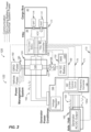
- the TRU controller 82 is communicatively coupled to the power management system 124, DC/AC converter 156, battery management system 154 and the generator power converter 164 components of voltage regulator 166, current control circuit 167, frequency converter 168 and the generator 162.
- the TRU controller 82 using additional information from the BMS 154 and generator 162, provide instructions to affect the generator output to the power form required by the TRU 26.
- the TRU controller 82 provides instructions to manage the power flow via the power management system 124 depending upon the operational status of the various power sources (i.e. grid power 182, energy storage device 152 and generator 162) as coupled with the TRU 26 power demand.
- the TRU controller 82 knows, the power requirements for the TRU system, and thereby, what power is needed.
- the TRU controller 82 is also programmed to ascertain whether or not grid power (e.g., 182) is available or not. If the grid power is available and TRU is On and energy storage device 152 (e.g., battery) SOC indicates a full charge, grid power will satisfy TRU system 26 power demand.
- TRU power demand is satisfied as first priority and then DC/AC inverter 156 is be activated to provide necessary charging to energy storage device 152 as second priority.
- DC/AC inverter 156 will be activated to provide necessary charging current.
- all TRU power demand is satisfied by the energy storage system 150 via the energy storage device.
- TRU power demand is satisfied by both the generator 162 & energy storage system 150.
- the power management system 124 receives power from a generator 162 directly and/or via a generator power converter 164.
- the power management system 124 may be may be a stand-alone unit, integral with the generator power converter 164, and/or integral with the TRU 26.
- the generator 162 can be axle or hub mounted configured to recover rotational energy when the transport refrigeration system 20 is in motion and convert that rotational energy to electrical energy, such as, for example, when the axle of the vehicle 22 is rotating due to acceleration, cruising, or braking.
- the generator 162 is configured to provide a first three phase AC power 163 comprising voltage V 1 , an AC current I 1 at a given frequency f 1 denoted by reference numeral 163.
- the generator 162 may be asynchronous or synchronous.
- the generator 162 may be DC, providing a first DC power 163a including a DC voltage and DC current denoted as V 1a , and DC current I 1a .
- the generator power converter 164 in one or more embodiments generates a second three phase AC power 165 including AC voltage V 2 , a second AC current I 2 at a selected frequency f 2 and is transmitted from the generator power converter 164 to the power management system 124 or otherwise as described herein.
- the TRU controller 82 identified the power requirements for the TRU 26 at least partially based on the RAT.
- the TRU controller 82 conveys the power requirements to the power management system 124 and/or the generator power converter 164 to convert the first three phase AC power 163 or first DC power 163a to the second three phase AC power 165 as necessary to satisfy the requirements of the TRU 26.
- the generator power converter 164 is an AC/AC converter and configured to receive the three phase AC power 163 (e.g., at AC voltage V 1 , AC current I 1 a frequency f 1 ), from the generator 162 and convert it to a second three phase AC power denoted 165 comprising the second three phase AC voltage V 2 , a second AC current I 2 at a selected frequency f 2 .
- the second three phase AC power 165 is transmitted from the generator power converter 164 to the power management system 124.
- the generator power converter 164 is configured to provide the second three phase AC power 165 based of the operating requirements of the TRU 26.
- the generator power converter 164 includes a voltage control function 166, a current control function 167, and frequency converter function 168, each configured to facilitate the conversion.
- the TRU controller 82 provides command signals denoted 169, 170, and 171 to a voltage control function 166, current control function 167, and frequency converter function 168 respectively.
- the command signals 169, 170, and 171 are generated by the TRU controller 82 based on the power consumption requirements of the TRU 26 as discussed further herein.
- the TRU controller 82 may receive status information as depicted by 172 regarding the generator 162, generator power converter 164, or the power management system 124 for mode selection and diagnostic purposes.
- the generator power converter 164 may be a stand-alone unit configured to be in close proximity to or even integral with the generator 162. In another example, the generator power converter 164 may be integral with the power management system 124 and/or the TRU 26.
- the voltage control function 166 includes a voltage regulation function and is configured to monitor the output voltage from the generator 162 and maintains a constant voltage out of the voltage control function 166.
- the voltage control function 166 communicates status to the TRU Controller 82.
- the current control function 167 monitors and communicates to the TRU 26 the status of current draw from the generator 162. The current may be limited depending on the power demands of the TRU 26.
- the frequency converter function 168 monitors the frequency of the three phase power 163 produced by the generator 162 and converts the three phase power 163 to the three phase power 165 exhibiting the desired frequency as determined by the voltage control function 166 and the TRU controller 82, for supply to the power management system 124 and ultimately the TRU 26.
- the communications may be over standard communication interfaces such as CAN, RS-485, and the like.
- the communications may be wired or wireless.
- the generator power converter 164 is an DC/AC converter and configured to receive DC power 163a (e.g., at DC voltage V 1a , DC current I 1a ), from the generator 162 and convert it to the second three phase AC power 165 comprising a second three phase AC voltage V 2 , a second AC current I 2 at a selected frequency f 2 .
- the second three phase AC power 165 is transmitted from the generator power converter 164 to the power management system 124 as described herein.
- the generator power converter 164 is configured to provide the second three phase AC power 165 based of the requirements of the TRU 26 as described above.
- the generator power converter 164 including the voltage control function 166, the current control function 167, and frequency converter function 168, are ach configured to facilitate the DC/AC conversion.
- the TRU controller 82 provides command signals denoted 169, 170, and 171 to a voltage control function 166, current control function 167, and frequency converter function 168 respectively, based on the power consumption requirements of the TRU 26 as discussed further herein.
- the voltage control function 166 includes a voltage regulation function and is configured to monitor the output DC voltage from the generator 162 and maintains a constant AC voltage out of the voltage control function 166.
- the current control function 167 monitors and communicates to the TRU 26 the status of current draw from the generator 162.
- the frequency converter function 168 monitors the frequency of the three phase power 165 produced by the generator converter 164 to ensure it exhibits the desired frequency as determined by the voltage control function 166 and the TRU controller 82, for supply to the power management system 124 and ultimately the TRU 26.
- one of the power sources 122 may include an energy storage system 150 operably coupled to the power management system 124.
- another power source 122 that the power management system 124 receives power from is the generator 162, whether directly and/or via a generator power converter 164.
- the grid power source 182 provides three phase AC power to the power management system 124 under selected conditions.
- the energy storage system 150 transmits three phase power 157 to and receives power from the power management system 124.
- the energy storage system 150 may include, but not be limited to the energy storage device 152, and AC/DC converter 156 and a battery management system 154.
- the power management system 124 provides three phase AC power 157 to an AC/DC converter 156 to formulate a DC voltage and current to charge and store energy on the energy storage device 152.
- the energy storage device 152 supplies DC voltage and current to the AC/DC converter 156 operating as a DC/AC converter to supply a three phase AC power 157 for powering the TRU 26.
- the battery management system 154 monitors the performance of the energy storage device 152. For example, monitoring the state of charge of the energy storage device 152, a state of health of the energy storage device 152, and a temperature of the energy storage device 152.
- the energy storage device 152 may include a battery system (e.g., a battery or bank of batteries), fuel cells, flow battery, and others devices capable of storing and outputting electric energy that may be direct current (DC).
- the energy storage device 152 may include a battery system, which may employ multiple batteries organized into battery banks through which cooling air may flow for battery temperature control, as described in U.S. patent application Ser. No. 62/616,077, filed January 11, 2018 .
- the battery system may have a voltage potential within a range of about two-hundred volts (200V) to about six-hundred volts (600V).
- the higher the voltage the greater is the sustainability of electric power which is preferred.
- the higher the voltage the greater is the size and weight of, for example, batteries in an energy storage device 152, which is not preferred when transporting cargo.
- the energy storage device 152 is a battery, then in order to increase either voltage and/or current, the batteries need to be connected in series or parallel depending upon electrical needs.
- the energy storage device 152 may be contained within the structure 27 of the TRU 26. In an embodiment, the energy storage device 152 is located with the TRU 26, however, other configurations are possible. In another embodiment, the energy storage device 152 may be located with the container 24 such as, for example, underneath the cargo compartment 40.
- the AC/DC converter 156 may be located with the container 24 such as, for example, underneath the cargo compartment 40, however, in some examples it may be desirable to have the AC/DC converter 156 in close proximity to the power management system 124 and/or the TRU 26 and TRU controller 82. It will be appreciated that in one or more examples, while particular locations are described with respect to connection and placement of selected components including the energy storage device 152 and/or AC/DC converter 156, such descriptions are merely illustrative. Varied location, arrangement and configuration of components is possible.
- the battery management system 154 and AC/DC converter 156 are operably connected to and interface with the TRU controller 82.
- the TRU controller 82 receives information regarding the status of energy storage system 150, including the energy storage device 152 to provide control inputs to the AC/DC converter 156 to monitor the energy storage device 152, control charge and discharge rates for the energy storage device 152 and the like.
- the power supply interface 120 may include, interfaces to various power sources 122 managed and monitored by power management system 124.
- the power management system 124 manages and determines electrical power flows in the power supply interface 120 based upon the operational needs of the TRU 26 and the capabilities of the components in the power supply interface 120, (e.g., generator 162, converter 164, energy storage device 152, and the like.
- the power management system 124 is configured to determine a status of various power sources 122, control their operation, and direct the power to and from the various power sources 122 and the like based on various requirements of the TRU 26.
- the power management system 124 there are five primary power flows managed by the power management system 124.
- the power flows will be transferred through different paths based on the requirements placed on the power management system 124 and particular configuration of the power supply interface 120.
- the power management system 124 operates as a central power bus to connect various power sources 122 together to supply the power needs of the TRU 26.
- the power management system 124 controls switching, directing, or redirecting power to/from the five power flows as needed to satisfy the power requirements of the TRU 26. Switching, directing, and redirecting may readily be accomplished by employing a bus control switching device 126 of the power management system 124.
- the bus control switching device 126 may include electromechanical and solid state semiconductor switching devices including relays, contactors, solid state contactors as well as semiconductor switching devices such as transistors, FETs, MOSFETS, IGBT's, thyristors, SCR's, and the like.
- the voltages and frequencies of the power whether supplied by the grid power supply 182, generator 162, generator converter 164, or the AC/DC converter 156 of the energy storage system 150 need to be synchronized to provide a common power source to be supplied to the TRU 26 and/or charge the energy storage device 152. Current draw will be determined by the TRU 26 and the need to charge the energy storage device 152.
- the generator power converter 164 output (the second three phase AC power 165) and/or grid power from the grid power source 182 and/or power directed to/from the energy storage system 150 is supplied to the bus control switching device 126 in an overlapping or break-before-make condition as determined by the bus control switching device 126 of the power management system.
- the AC/DC converter 156 when operating as a DC to AC converter synchronizes the voltage and frequency of the three phase power (e.g., 157) generated via the energy storage system 150 with the power connected bus control switching device 126 in order to transfer power from the energy storage device 152 to the power management system 124 (an thereby the TRU 26) as needed.
- grid power from the grid power source 182 provided to the power management system 124 is directed by the bus control switching device 126 once connected and the AC/DC converter 156 monitor the bus voltage and frequency to determine if the above parameters are equal before connectivity is permitted. This will allow minimum disruption of the power bus system. In other words, anytime two or more power sources are available, the bus control switching device, and the AC/DC convert 156 ensure that power is matched and synchronized to enable connectivity.
- the power bus control device 126 communicates to the TRU controller 82 to determine status of flows connected.
- the power management system 124, and or the TRU controller 82 provides visual indications of which source (e.g., grid power source 182, generator 162 or energy storage system 150) is selected and operating on the bus control switching device 126.
- FIGS. 4A-4H each providing a simplified diagram depicting each of the eight identified power flows combinations.
- FIGS. 4A-4C depict power flows for power supplied from the generator 162 and/or generator power converter 164 (e.g., second three phase AC power).
- the logic employed by the TRU controller 82 for directing the power in the power management system 124 determines if the TRU 26 is operating. If so, and the energy storage system 150 indicates that the energy storage device 120 is exhibiting a charge state that is less than a selected threshold, then the power management system 124 directs power to both the TRU 26 and the energy storage system 150 for recharging the energy storage device 152.
- priority is given to satisfying the power requirements of the TRU 26. Any remaining power may be directed to the recharging application for the energy storage system 150. It should be appreciated that while particular threshold of 80% is disclosed and employed for the described embodiments, such values and description are merely illustrative. Other values and applications for the thresholds are possible.
- FIG 4B the figure depicts a second instance for power flows for power supplied from the generator 162 and/or generator power converter 164.
- the power management system 124 directs power to only the TRU 26, (as the and the energy storage system 150 does not yet require recharging).
- FIG 4C a third power flow governed by the power management system 124 for power supplied from the generator 162 and/or generator power converter 164.
- the logic employed by the TRU controller 82 for directing the power in the power management system 124 addresses an instance when the TRU 26 is inoperative, and the energy storage system 150 indicates that the energy storage device 152 is exhibiting a state of charge that is less than a selected threshold (in this instance 100%, though other thresholds are possible).
- the power management system 124 directs power to only to the energy storage system 150 for recharging the energy storage device 152.
- priority is given to satisfying the power requirements of energy storage system 150 and secondarily to providing power to the TRU 26.
- FIGS. 4D-4F depict power flows for power supplied from the grid power source 182.
- the logic employed by the TRU controller 82 for directing the power from the grid power source 182 in the power management system 124 determines if the TRU 26 is operating and the generator 162 (or the generator power converter 164) is inoperative. If so, and the energy storage system 150 indicates that the energy storage device 152 is exhibiting a charge state that is less than a selected threshold, then the power management system 124 directs power to both the TRU 26 and the energy storage system 150 for recharging the energy storage device 152. In an embodiment, once again, priority is given to satisfying the power requirements of the TRU 26.
- any remaining power may be directed to the recharging application for the energy storage system 150. It should be appreciated that while particular threshold of 80% is disclosed and employed for the described embodiments, such values and description are merely illustrative. Other values and applications for the thresholds are possible.
- FIG 4E the figure depicts a second instance for power flows for power supplied from the grid power source 182 when the generator 162 is inoperative.
- the power management system directs power to only the TRU 26, (as the energy storage system 150 does not yet require recharging).
- FIG 4F a third power flow governed by the power management system 124 for power supplied from the grid power source 182 when the generator 162 is inoperative.
- the logic employed by the TRU controller 82 for directing the power in the power management system 124 addresses an instance when the TRU 26 is also inoperative, and the energy storage system 150 indicates that the energy storage device 152 is exhibiting a state of charge that is less than a selected threshold (in this instance 100%, though other thresholds are possible).
- the power management system 124 directs power to only to the energy storage system 150 for recharging the energy storage device 152. In an embodiment, priority is given to satisfying the power requirements of energy storage system 150.
- FIGS. 4G and 4H depict power flows for power supplied to the TRU 26 under selected conditions for operating from the energy storage system 150 as well.
- power flows to the TRU 26 are provided from the generator 162 and/or generator power converter 164 (e.g., second three phase AC power 165) as well as from the energy storage system 150.
- the logic employed by the TRU controller 82 for directing the power in the power management system 124 determines if the TRU 26 is operating.
- the power management system 124 directs power from both the generator 162 (or generator power converter 164) and the energy storage system 150 is directed to the TRU 26.
- a threshold of 10 percent is employed for the state of charge of the energy storage device 152.
- power is provided by the energy storage system 150 and thereby discharging the energy storage device 152.
- priority is given to satisfying the power requirements of the TRU 26. This embodiment may be employed under conditions where the output power of the generator 162 and/or generator power converter 164 is less that that needed to operate the TRU 26.
- threshold of 10% is disclosed and employed for the described embodiments, such values and description are merely illustrative. Other values and applications for the thresholds are possible. For example, in some instances it may be desirable prioritize operation of the TRU 26 such that fully draining the energy storage device 152 is acceptable. Likewise, in other embodiments, it may be desirable to modify the function or curtail the operation of the TRU 26 to avoid excessively discharging the energy storage device 152.
- the figure depicts a second instance for power flows from the energy storage system 150 alone.
- the power management system 124 directs power to the TRU 26.
- a threshold of 10 percent is employed for the state of charge of the energy storage device 152.
- power is provided by the energy storage system 150 and thereby discharging the energy storage device 152.
- priority is given to satisfying the power requirements of the TRU 26.
- this embodiment may be employed under conditions where the output power of the generator 162 and/or generator power converter 164 is less that that needed to operate the TRU 26.
- threshold of 10% is disclosed and employed for the described embodiments, such values and description are merely illustrative. Other values and applications for the thresholds are possible. For example, in some instances it may be desirable prioritize operation of the TRU 26 such that fully draining the energy storage device 152 is acceptable. Likewise, in other embodiments, it may be desirable to modify the function or curtail the operation of the TRU to avoid excessively discharging the energy storage device 152.
- the power supply interface 120 is configured such that, in selected modes of operation power is directed to the TRU 26 from the tractor or vehicle 22.
- the energy storage device 152 exhibit a SOC below a selected threshold e.g., ⁇ 10% and the generator 162/generator power converter 164 is not operable but the TRU system 26 is operable and requires power
- TRU power could be drawn from the power system of the tractor or truck. (i.e. tie into the energy storage device or generator of the tractor/truck).
- the described embodiments while generally referring the generator 162 being installed on the trailer portion of the vehicle, 22, such description is merely illustrative. In another embodiment, the generator 162 or another generator could be installed at a hub or axle of the tractor portion of the vehicle 22 without loss of generality and still be fully applicable to the described embodiments.
- the tractor/truck power may be routed to the power management system through a grid plug 185. Alternately connectable between the grid power source 182 and the vehicle power. For example, in operation, when vehicle 22 trailer is in operation, for example, on delivery, grid plug 185 would be plugged into the tractor/trailer's electric PTO and act as mobile grid source.
- the TRU controller 82 would be programmed to determine if the grid plug is active and if so, to pull power (or supplement generator power) only if energy storage device SOC is below threshold as alternative to modify the function or curtail the operation of the TRU system 26.
- the power sources 122 may include, but not be limited to an energy storage system 150 operably coupled to the power management system 124 and the grid power source 182.
- the generator 162 whether directly and/or via a generator power converter 164 is operably connected to the energy storage system 150, and more specifically to the energy storage device 152.
- the generator 162 is an AC generator 162
- the generator power converter 164 is an AC/DC converter and configured to receive three phase AC power 163 (e.g., at AC voltage V 1 , AC current I 1 and frequency f 1 ), from the generator 162 and convert it to the third DC power denoted 165b comprising a DC voltage V 3 , a third DC current I 3 .
- the generator 162 when the generator 162 is a DC generator (denoted in the figures as 162a, the generator power converter, denoted as 164a is a DC/DC converter and configured to receive DC power denoted 163a (e.g., at DC voltage V 1a , DC current I 1a ), from the generator 162a and convert it to the third DC power denoted 165b comprising a DC voltage V 3 , a third DC current I 3 .
- DC power denoted 163a e.g., at DC voltage V 1a , DC current I 1a
- the third DC power 165b is transmitted from the generator power converter 164 (or 164a) directly to the energy storage system 150.
- the generator power converter 164, 164a is configured to provide the third DC power 165b based of the requirements of the TRU 26 as described above.
- the generator power converter 164, 164a including the voltage control function 166 (see for example, FIG. 3 ), the current control function 167 ( FIG. 3 ), is configured to facilitate the AC/DC conversion for generator power converter 164, and likewise the DC/DC conversion for generator power converter 164a in the example.
- the TRU controller 82 provides command signals denoted 169, 169a to the voltage control function 166, and/or current control function 167 respectively, based on the power consumption requirements of the TRU 26 as discussed further herein.
- the voltage control function 166 includes a voltage regulation function and is configured to monitor the output AC or DC voltage from the generator 162 and maintains a constant DC voltage out of the voltage control function 166 for supply to the energy storage system 220 and the energy storage device 152.
- the current control function 167 monitors and communicates to the TRU 26 the status of current draw from the generator 162, 162a. Once again, the status of the generator 162, 162a is monitored by the TRU controller 82 via line 172, 172a.
- the generator 162, 162a whether directly and/or via a generator power converter 164 is operably connected to the energy storage system 150.
- the energy storage device 152 includes eletrical switching device 158 controllable by the TRU controller and/or BMS 154 employed as a DC power manager.
- the electrical switching device 158 is configured to connect power flows of the generator162/generator power converter 164, 164a, and battery of the energy storage device 152 to feed DC power 155 as needed to the DC/AC converter 156 and to the power management system 124 to satisfy TRU demand.
- the TRU demand will be satisfied by either all power from the generator 162/generator converter 164, 164a, all power from the battery or some combination of power from generator 262/generator converter 164, 164a and the battery. For example, if the TRU power demand is less than the generator power available, TRU power requirements are met with power from the generator 162/generator converter 164, 164a and any remaining generator power is directed to charge the battery of the energy storage device. Control of the electrical circuitry (through BMS 154) will manage flow into and out of battery and meet TRU demand as needed.
- the energy storage system 150 transmits power to and receives power from the power management system 124 via the AC/DC converter 156 operating as a DC/AC converter.
- the energy storage system 150 includes the energy storage device 152, and AC/DC converter 156 and a battery management system 154.
- the power management system 124 when operating from grid power source 182, the power management system 124 provides three phase AC power to the TRU 26 as described with the power flows above.
- the power management system 124 may also direct three phase AC power to the AC/DC converter 156 to formulate a DC voltage and current to charge and store energy on the energy storage device 152.
- the energy storage device 152 supplies DC voltage and current to the AC/DC converter 156 operating as a DC/AC converter to supply a three phase AC voltage and current to the power management system 124 for powering the TRU 26.
- the TRU 26 may be operated from the energy storage system 150 provided the state of charge of the energy storage device 152 exceeds a selected threshold.
- the selected threshold may be 10% state of charge.
- the battery management system 154 monitors the perfomance of the energy storage device 152. For example, monitoring the state of charge of the energy storage device 152, a state of health of the energy storage device 152, and a temperature of the energy storage device 152.
- the battery management system 154 and AC/DC converter 156 are operably connected to and interface with the TRU controller 82.
- the TRU controller 82 receives information regarding the status of energy storage system 150, including the energy storage device 152 to provide control inputs to the AC/DC converter 156 to monitor the energy storage device, 152, control charge and discharge rates for the energy storage device 152 and the like.
- examples of the energy storage device 152 may include a battery system (e.g., a battery or bank of batteries), fuel cells, and others devices capable of storing and outputting electric energy that may be direct current (DC). If the energy storage system 150 includes a battery system for the energy storage device 152, the battery system may have a voltage potential within a range of about two-hundred volts (200V) to about six-hundred volts (600V).
- the energy storage device 152 may be contained within the structure 27 of the TRU 26.
- the energy storage device 152 may be located with the TRU 26, however other configurations are possible.
- the energy storage device 152 may be located with the container 24 such as, for example, underneath the cargo compartment 40.
- the AC/DC converter 156 may be located with the container 24 such as, for example, underneath the cargo compartment 40, however, in some embodiments it may be desirable to have the AC/DC converter 156 in close proximity to the power management system 124 and/or the TRU 26 and TRU controller 82. It will be appreciated that, while particular locations are described with respect to connection and placement of selected components including the energy storage device 152 and/or AC/DC converter 156, such descriptions are merely illustrative and are not intended to be limiting. Varied location, arrangement and configuration of components is possible.
- the power supply interface 220 may include, interfaces to various power sources 122 managed and monitored by power management system 124.
- the power management system 124 manages and determines electrical power flows in the power supply interface 220 based upon the operational needs of the TRU 26 and the capabilities of the components in the power supply interface 220, (e.g., generator 162, 162a, generator power converter 164, 164a, energy storage device 152, grid power source 182, and the like.
- the power management system 124 is configured to determine a status of various power sources 122, control their operation, and direct the power to and/or from the various power sources 122 and the like, based on various operational requirements of the TRU 26.
- the TRU controller 82 receives various signals indicative of the operational state of the TRU 26 and determines the power requirements for the TRU system 26 accordingly and directs the power supply interface 220 and specifically the power management system 124 to direct power accordingly to address the requirements of the TRU 26.
- the TRU controller 82 monitors the RAT and optionally the SAT as measured by the temperature sensors 142 and 146 respectively.
- the TRU controller 82 estimates the power requirements for the TRU 26 based on the RAT (among others) and provides commands accordingly to the various components of the power supply interface 220 and specifically the power management system 124, energy storage system 150, and generator power converter 164 to manage the generation, conversion, and routing of power in the power supply interface 220 and TRU system 26.
- the power sources 122 may include to an energy storage system 150 operably coupled to the power management system 124a, which is similar to the power management system 124 of the earlier embodiments, but including additional functions and features, and the grid power source 182.
- the generator 162 whether directly and/or via a generator power converter 164 is operably connected to the energy storage system 150, and more specifically to the energy storage device 152.
- the generator 162 is an AC generator 162
- the generator power converter 164 is an AC/DC converter and configured to receive three phase AC power 163 (e.g., at AC voltage V 1 , AC current I 1 and frequency f 1 ), from the generator 162 and convert it to the third DC power denoted 165b comprising a DC voltage V 3 , a third DC current I 3 .
- the generator 162 is a DC generator denoted in the figures as 162a
- the generator power converter, denoted as 164a is a DC/DC converter and configured to receive DC power denoted 163a (e.g., at DC voltage V 1a , DC current I 1a ), from the generator 162a and convert it to the third DC power denoted 165b comprising a DC voltage V 3 , a third DC current I 3 .
- the third DC power 165b is transmitted from the generator power converter 164 (or 164a) directly to the energy storage system 150.
- the generator power converter 164, 164a is configured to provide the third DC power 165b based of the requirements of the TRU 26 as described above.
- the generator power converter 164, 164a including the voltage control function 166 (see for example, FIG. 3 ), the current control function 167 ( FIG. 3 ), is configured to facilitate the AC/DC conversion for generator power converter 164, and likewise the DC/DC conversion for generator power converter 164a of an alternative embodiment.
- the TRU controller 82 provides command signals denoted 169, 169a to the voltage control function 166, and/or current control function 167 respectively, based on the power consumption requirements of the TRU 26 as discussed further herein.
- the voltage control function 166 includes a voltage regulation function and is configured to monitor the output AC or DC voltage from the generator 162 and maintains a constant DC voltage out of the voltage control function 166 for supply to the energy storage system 320 and the energy storage device 152.
- the current control function 167 monitors and communicates to the TRU 26 the status of current draw from the generator 162, 162a. Once again, the status of the generator 162, 162a is monitored by the TRU controller 82via line 172, 172a.
- the generator 162, 162a whether directly and/or via a generator power converter 164 is operably connected to the energy storage system 150.
- the energy storage device 152 includes electrical switching device 158 controllable by the TRU controller and/or BMS 154 employed as a DC power manager.
- the electrical switching device 158 is configured to connect power flows of the generator162/generator power converter 164, 164a, and battery of the energy storage device 152 to feed DC power 155 as needed to the DC/AC converter 156 and to the power management system 124 to satisfy TRU demand.
- the TRU demand will be satisfied by either all power from the generator 162/generator converter 164, 164a, all power from the battery or some combination of power from generator 262/generator converter 164,164a and the battery. For example, if the TRU power demand is less than the generator power available, TRU power requirements are met with power from the generator 162/generator converter 164,164a and any remaining generator power is directed to charge the battery of the energy storage device. Control of the electrical circuitry (through BMS 154) will manage flow into and out of battery and meet TRU demand as needed.
- the generator 162, 162a whether directly and/or via a generator power converter 164 is operably connected to the energy storage system 150, and more specifically to the energy storage device 152.
- the energy storage system 150 transmits power to and receives power from the power management system 124a.
- the energy storage system 150 includes the energy storage device 152, and AC/DC converter 156 and a battery management system 154.
- the power management system 124a When operating from grid power source 182, the power management system 124a provides three phase AC power to the TRU 26 as described with the power flows above.
- the power management system 124a may also direct three phase AC power to the AC/DC converter 156 to formulate a DC voltage and current to charge and store energy on the energy storage device 152.
- the energy storage device 152 supplies DC voltage and current to the AC/DC converter 156 operating as a DC/AC converter to supply a three phase AC voltage and current to the power management system 124 for powering the TRU 26.
- the TRU 26 may be operated from the energy storage system 150 provided the state of charge of the energy storage device 152 exceeds a selected threshold.
- the selected threshold may be 10% state of charge.
- the battery management system 154 monitors the performance of the energy storage device 152. For example, monitoring the state of charge of the energy storage device 152, a state of health of the energy storage device 152, and a temperature of the energy storage device 152.
- the battery management system 154 and AC/DC converter 156 are operably connected to and interface with the TRU controller 82.
- the TRU controller 82 receives information regarding the status of energy storage system 150, including the energy storage device 152 to provide control inputs to the AC/DC converter 156 to monitor the energy storage device, 152, control charge and discharge rates for the energy storage device 152 and the like.
- examples of the energy storage device 152 may include a battery system (e.g., a battery or bank of batteries), fuel cells, and others devices capable of storing and outputting electric energy that may be direct current (DC) as discussed herein.
- a battery system e.g., a battery or bank of batteries
- fuel cells e.g., fuel cells, and others devices capable of storing and outputting electric energy that may be direct current (DC) as discussed herein.
- DC direct current
- the power supply interface 320 may include, interfaces to various power sources 122 managed and monitored by power management system 124a.
- the power management system 124 manages and determines electrical power flows in the power supply interface 320 based upon the operational needs of the TRU 26 and the capabilities of the components in the power supply interface 320, (e.g., generator 162, 162a, generator power converter 164, 164a, energy storage device 152, grid power source 182, and the like.
- the power management system 124a is configured to determine a status of various power sources 122, control their operation, and direct the power to and/or from the various power sources 122 and the like, based on various operational requirements of the TRU 26.
- the power management system 124a may also include an AC/DC converter 128 configured to receive the incoming three phase AC voltage 157 and convert a portion thereof to a DC voltage 129 to facilitate maintenance, configuration and operation of the TRU 26.
- the addition of AC/DC converter 128 eliminates the need for a separate TRU battery to maintain operation of the TRU controller 82.
- the DC voltage generated by the AC/DC converter 129 is also employed to power selected sensors and components of the TRU system 26.
- generating the needed low voltage DC power in the power management systems simplifies the wiring and routing of the TRU system 26 and power supply interface 320 by eliminating an additional set of DC cabling from the energy storage device 152 beyond the cabling going to the AC/DC converter 156.
- the power management system 124a would require two sets of DC cabling (a high voltage set directed to the AC/DC converter 156, and a low voltage set optionally directed to the TRU directly) out of energy storage device vs. only the single DC cabling in the described embodiments.
- the TRU controller 82 receives various signals indicative of the operational state of the TRU 26 and determines the power requirements for the TRU system 26 accordingly and directs the power supply interface 320 and specifically the power management system 124a to direct power accordingly to address the requirements of the TRU 26.
- the TRU controller 82 can monitor the RAT and optionally the SAT as measured by the temperature sensors 142 and 146 respectively.
- the TRU controller 82 estimates the power requirements for the TRU 26 based on the RAT (among others) and provides commands accordingly to the various components of the power supply interface 320 and specifically the power management system 124, energy storage system 150, and generator power converter 164 to manage the generation, conversion, and routing of power in the power supply interface 320 and TRU system 26.
- the TRU 26 may further include a renewable power source 110 ( FIG. 1 ) configured to recharge the batteries of the energy storage device 152.
- a renewable power source 110 may be solar panels mounted, for example, to the outside of the top wall 30 of the container 24 (also see FIG. 1 ).
- the renewable power source 110 could generate all or a portion of the needed low voltage DC power for the TRU controller 82.
- Benefits of the present disclosure when compared to more traditional systems include no fuel carriage, fuel system and fuel consumption, and a refrigeration unit that emits less noise and no combustion byproducts. Yet further, the present disclosure includes an energy storage device that is conveniently and efficiently recharged to meet the power demands of the refrigeration unit.
- embodiments can be in the form of processor-implemented processes and devices for practicing those processes, such as a processor.
- Embodiments can also be in the form of computer program code containing instructions embodied in tangible media, such as network cloud storage, SD cards, flash drives, floppy diskettes, CD ROMs, hard drives, or any other computer-readable storage medium, wherein, when the computer program code is loaded into and executed by a computer, the computer becomes a device for practicing the embodiments.
- Embodiments can also be in the form of computer program code, for example, whether stored in a storage medium, loaded into and/or executed by a computer, or transmitted over some transmission medium, loaded into and/or executed by a computer, or transmitted over some transmission medium, such as over electrical wiring or cabling, through fiber optics, or via electromagnetic radiation, wherein, when the computer program code is loaded into an executed by a computer, the computer becomes a device for practicing the embodiments.
- the computer program code segments configure the microprocessor to create specific logic circuits.
Landscapes
- Engineering & Computer Science (AREA)
- Physics & Mathematics (AREA)
- Thermal Sciences (AREA)
- Mechanical Engineering (AREA)
- Chemical & Material Sciences (AREA)
- Combustion & Propulsion (AREA)
- General Engineering & Computer Science (AREA)
- Supply And Distribution Of Alternating Current (AREA)
- Devices That Are Associated With Refrigeration Equipment (AREA)
Claims (15)
- Unité de réfrigération de transport, TRU, (26) et système d'alimentation comprenant :un compresseur (58) configuré pour comprimer un réfrigérant, le compresseur (58) ayant un moteur de compresseur (60) configuré pour entraîner le compresseur (58) ;un échangeur de chaleur d'évaporateur (76) couplé de manière fonctionnelle au compresseur (58) ;un ventilateur d'évaporateur (78) configuré pour fournir un flux d'air de retour (134) à partir d'une entrée d'air de retour (136) et faire circuler le flux d'air de retour (134) sur l'échangeur de chaleur d'évaporateur (76) ;un capteur de température d'air de retour, RAT, (142) disposé dans le flux d'air de retour (134) et configuré pour mesurer la température du flux d'air de retour (134) ;un dispositif de commande de TRU (82) connecté de manière fonctionnelle au capteur de RAT (142) et configuré pour exécuter un processus pour déterminer des besoins en alimentation CA pour la TRU (26) sur la base au moins de la RAT ;un convertisseur de puissance de générateur (164), le convertisseur de puissance de générateur (164) étant configuré pour recevoir une alimentation CA triphasée de générateur (163) fournie par un générateur CA (162) et transmettre une seconde alimentation CC (165b) ;un système de stockage d'énergie (150) configuré pour recevoir la seconde alimentation CC (165b) et fournir une première alimentation CA triphasée (157) et recevoir une seconde alimentation CA triphasée (157) ; etun système de gestion d'alimentation (124) configuré pour recevoir la première alimentation CA triphasée (157) et diriger au moins une partie de la première alimentation CA triphasée (157) vers la TRU (26) en fonction, au moins en partie, des besoins en alimentation CA ;dans laquelle le convertisseur de puissance de générateur (164) est connecté de manière fonctionnelle au dispositif de commande (82) de la TRU, le convertisseur de puissance de générateur (164) comprenant une fonction de commande de tension (166), une fonction de commande de courant (167), au moins la fonction de commande de tension (166) réagissant au moins en partie aux besoins en alimentation CA.
- TRU (26) et système d'alimentation selon la revendication 1, comprenant en outre une source d'alimentation de réseau (182) configurée pour fournir une alimentation CA triphasée de réseau au système de gestion d'alimentation (124).
- TRU (26) et système d'alimentation selon la revendication 1, dans lesquels le convertisseur de puissance de générateur (164) comprend un convertisseur CA/CC et l'alimentation CA triphasée de générateur (163) présente une première tension CA (V1) et un premier courant CA (I1), à une première fréquence (f1), et la seconde alimentation CC (165b) présente une seconde tension CC (V3) et un second courant CC (I3).
- TRU (26) et système d'alimentation selon la revendication 1, dans lesquels le système de stockage d'énergie (150) comporte :un dispositif de stockage d'énergie (152) ;un dispositif de commutation (158) ; etau moins l'un d'un convertisseur CC/CA (156) configuré pour fournir la première alimentation CA triphasée (157) au système de gestion d'alimentation (124) en fonction, au moins en partie, des besoins en alimentation CA et un convertisseur CA/CC (156) configuré pour recevoir la seconde alimentation CA triphasée (157) pour alimenter le dispositif de stockage d'énergie (152).
- TRU et système d'alimentation selon la revendication 4, dans lesquels le dispositif de commutation (158) est configuré pour diriger les flux de l'alimentation CC (155) dans le système de stockage d'énergie (150) en fonction, au moins en partie, des besoins en alimentation CA, la direction comprenant les étapes consistant à :diriger la seconde alimentation CC (165b) vers au moins l'un du dispositif de stockage d'énergie (152) et du convertisseur CC/CA (156) ;diriger l'alimentation CC (155) du dispositif de stockage d'énergie (152) vers le convertisseur CC/CA (156) ; etrecevoir l'alimentation CC (155) du convertisseur CA/CC (156) et la fournir au dispositif de stockage d'énergie (152) ;
oudans lesquels le dispositif de stockage d'énergie (152) comporte au moins l'une d'une batterie, d'une pile à combustible et d'une batterie à flux. - TRU et système d'alimentation selon la revendication 4, comprenant également un système de gestion de batterie (154) connecté de manière fonctionnelle au dispositif de commande de TRU (82) et configuré pour surveiller au moins un état de charge du dispositif de stockage d'énergie (152).
- TRU (26) et système d'alimentation selon la revendication 6, dans lesquels le convertisseur CC/CA (156) et le convertisseur CA/CC (156) sont intégrés et dans lequel le convertisseur CC/CA (156) ou le convertisseur CA/CC (156) est connecté de manière fonctionnelle au dispositif de commande (82) de la TRU et configuré pour diriger des flux d'alimentation vers le système de gestion d'alimentation (124) et à partir du système de gestion d'alimentation (124) en fonction, au moins en partie, d'au moins l'un des besoins en alimentation CA et de l'état de charge du dispositif de stockage d'énergie (152).
- TRU et système d'alimentation selon la revendication 7, dans lesquels le système de gestion d'alimentation (124) est configuré pour recevoir la première alimentation CA triphasée (157) provenant du système de stockage d'énergie (150) et une alimentation CA triphasée de réseau provenant d'une connexion à une alimentation de réseau (185) ; et pour fournir au moins l'une d'une alimentation CA triphasée sélectionnée à la TRU (26) et de la seconde alimentation CA triphasée (157) au système de stockage d'énergie (150).
- TRU (26) et système d'alimentation selon la revendication 7, dans lesquels le système de gestion d'alimentation (124) comporte un dispositif de commutation de commande d'alimentation (126), le dispositif de commutation de commande d'alimentation (126) réagissant au dispositif de commande (82) de la TRU et étant configuré pour diriger une pluralité de flux d'alimentation dans la TRU (26) et le système d'alimentation, la pluralité de flux d'alimentation étant au moins en partie basée sur au moins l'un des besoins en alimentation CA et d'un état de charge du dispositif de stockage d'énergie (152) du système de stockage d'énergie (150).
- TRU (26) et système d'alimentation selon la revendication 9, dans lesquels une première partie des flux d'alimentation de la pluralité de flux d'alimentation comporte :la réception d'une alimentation CA triphasée de réseau à partir du réseau si la source d'alimentation de réseau (182) est opérationnelle ; etla direction d'au moins une partie de l'alimentation CA triphasée de réseau vers la TRU (26) et le système de stockage d'énergie (150) si la TRU (26) est opérationnelle et si un dispositif de stockage d'énergie (152) du système de stockage d'énergie (150) présente un état de charge inférieur à un seuil sélectionné ; oula direction d'au moins une partie de l'alimentation CA triphasée de réseau vers la TRU (26) si la TRU (26) est opérationnelle et si un dispositif de stockage d'énergie (152) du système de stockage d'énergie (150) présente un état de charge supérieur ou égal à environ le seuil sélectionné ; oula direction d'au moins une partie de l'alimentation CA triphasée de réseau vers le système de stockage d'énergie (150) si la TRU (26) n'est pas opérationnelle et si un dispositif de stockage d'énergie (152) du système de stockage d'énergie (150) présente un état de charge inférieur à un second seuil sélectionné.
- TRU (26) et système d'alimentation selon la revendication 9, dans lesquels une seconde partie de flux d'alimentation de la pluralité de flux d'alimentation comporte :la réception d'une alimentation CA triphasée (157) provenant du système de stockage d'énergie (150) ;la réception d'une alimentation CA triphasée de réseau à partir de la source d'alimentation de réseau (182) si la source d'alimentation CA de réseau est opérationnelle ;la synchronisation et la combinaison de l'alimentation CA triphasée (157) provenant du système de stockage d'énergie (150) et de l'alimentation CA triphasée de réseau ; etla direction de l'alimentation CA triphasée combinée vers la TRU (26) si la TRU est opérationnelle et si un dispositif de stockage d'énergie (152) du système de stockage d'énergie (150) présente un état de charge supérieur ou égal à environ un autre seuil sélectionné.
- Procédé de génération et de direction d'alimentation vers un système d'unité de réfrigération de transport, TRU, (26) ayant un compresseur (58) configuré pour comprimer un réfrigérant, un échangeur de chaleur d'évaporateur (76) couplé de manière fonctionnelle au compresseur (58) ; un ventilateur d'évaporateur (78) configuré pour fournir un flux d'air de retour (134) à partir d'une admission d'air de retour (136) et faire circuler le flux d'air de retour (134) sur l'échangeur de chaleur d'évaporateur (76) ; un capteur de température d'air de retour, RAT, (142) disposé dans le flux d'air de retour (134) et configuré pour mesurer la température du flux d'air de retour (134) ; et un dispositif de commande (82) de la TRU, le procédé comportant :connecté de manière opérationnelle au capteur RAT (142) au dispositif de commande TRU (82) ;la détermination de besoins en alimentation CA pour la TRU (26) sur la base au moins de la RAT ;la connexion fonctionnelle d'un convertisseur de puissance de générateur (164) à un générateur CA (162), le convertisseur de puissance de générateur (164) étant configuré pour recevoir l'alimentation CA triphasée de générateur (163) fournie par le générateur CA (162) et transmettre une seconde alimentation CC (165b),dans lequel le convertisseur de puissance de générateur (164) est connecté de manière fonctionnelle au dispositif de commande (82) de la TRU, le convertisseur de puissance de générateur (164) comprenant une fonction de commande de tension (166), une fonction de commande de courant (167), dans lequel au moins la fonction de commande de tension (166) réagit au moins en partie aux besoins en alimentation CA ;la connexion fonctionnelle d'un système de stockage d'énergie (150), le système de stockage d'énergie (150) pouvant recevoir la seconde alimentation CC (165b) et une alimentation CA triphasée (157), fournir la première alimentation CA triphasée (157) et recevoir une seconde alimentation CA triphasée (157) ; etla connexion fonctionnelle d'un système de gestion d'alimentation (124) au convertisseur de puissance de générateur (164) et à la TRU (26), le système de gestion d'alimentation (124) étant configuré pour recevoir la seconde alimentation CA triphasée (157) et pour diriger l'alimentation vers la TRU (26) sur la base, au moins en partie, des besoins en alimentation CA.
- Procédé selon la revendication 12, comprenant également :la connexion fonctionnelle d'une source d'alimentation de réseau (182) pour fournir l'alimentation CA triphasée de réseau au système de gestion d'alimentation (124) ;
et/oula conversion, par le convertisseur de puissance de générateur (164), de l'alimentation CA triphasée de générateur (163) avec une première tension CA (V1) et un premier courant CA (I1) à une première fréquence (f1), en la seconde alimentation CC (165b) avec une seconde tension CC (V3) et un second courant CC (I3). - Procédé selon la revendication 12, comprenant également au moins l'une des étapes consistant à :fournir la première alimentation CA triphasée (157) au système de gestion d'alimentation en fonction, au moins en partie, des besoins en alimentation CA par un convertisseur CC/CA (156) configuré pour convertir une première alimentation CC (155) en la première alimentation CA triphasée (157) ; etrecevoir la seconde alimentation CA triphasée (157) du système de gestion d'alimentation (126) et convertir la seconde alimentation CA triphasée (157) en alimentation CC (155) pour charger le système de stockage d'énergie (150) ;dans lequel le système de stockage d'énergie (150) comporte un dispositif de stockage d'énergie (152), un dispositif de commutation (158) et au moins l'un d'un convertisseur CA/CC (156) et d'un convertisseur CC/CA (156) ;le procédé comprenant éventuellement également la configuration du dispositif de commutation (158) pour diriger les flux d'alimentation CC dans le système de stockage d'énergie (150) en fonction des besoins en alimentation CA, la direction comprenant :l'application de la seconde alimentation CC (165b) à au moins l'un du dispositif de stockage d'énergie (152) et du convertisseur CC/CA (156) ;l'application de l'alimentation CC (155) du dispositif de stockage d'énergie (152) au convertisseur CC/CA (156) ; etla réception de l'alimentation CC (155) du convertisseur CA/CC (156) et sa fourniture au dispositif de stockage d'énergie (152).
- Procédé selon la revendication 14, comprenant également la direction d'une pluralité de flux d'alimentation vers la TRU (26) et le système d'alimentation avec un dispositif de commutation de commande d'alimentation (126) du système de gestion d'alimentation (124), le dispositif de commutation de commande d'alimentation (126) réagissant au dispositif de commande (82) de la TRU, la pluralité de flux d'alimentation étant basée au moins en partie sur au moins les besoins en alimentation CA, un état de charge d'un dispositif de stockage d'énergie (152) du système de stockage d'énergie (150) ; éventuellement dans lequel une première partie des flux d'alimentation de la pluralité de flux d'alimentation comprend :la réception d'une alimentation CA triphasée de réseau à partir du réseau si la source d'alimentation de réseau (182) est opérationnelle ; etla direction d'au moins une partie de l'alimentation CA triphasée de réseau vers la TRU (26) et le système de stockage d'énergie (150) si la TRU (26) est opérationnelle et si un dispositif de stockage d'énergie (152) du système de stockage d'énergie (150) présente un état de charge inférieur à un seuil sélectionné ; oula direction d'au moins une partie de l'alimentation CA triphasée de réseau vers la TRU (26) si la TRU (26) est opérationnelle et si le dispositif de stockage d'énergie (152) du système de stockage d'énergie (150) présente un état de charge supérieur ou égal à environ le seuil sélectionné ; oula direction d'au moins une partie de l'alimentation CA triphasée de réseau vers le système de stockage d'énergie (150) si la TRU (26) n'est pas opérationnelle et si le dispositif de stockage d'énergie (152) du système de stockage d'énergie (150) présente un état de charge inférieur à un second seuil sélectionné ;éventuellement dans lequel une seconde partie des flux d'alimentation de la pluralité de flux d'alimentation comporte :la réception de la première alimentation CA triphasée (157) provenant du système de stockage d'énergie (150) ;la réception d'une alimentation CA triphasée de réseau à partir de la source d'alimentation de réseau (182) si la source d'alimentation CA de réseau est opérationnelle ; etla synchronisation et la combinaison de la première alimentation CA triphasée (157) provenant du système de stockage d'énergie (150) et de l'alimentation CA triphasée de réseau ; etla direction de l'alimentation CA triphasée combinée vers la TRU (26) si la TRU (26) est opérationnelle et si un dispositif de stockage d'énergie du système de stockage d'énergie présente un état de charge supérieur ou égal à environ un autre seuil sélectionné.
Applications Claiming Priority (3)
| Application Number | Priority Date | Filing Date | Title |
|---|---|---|---|
| US201862738676P | 2018-09-28 | 2018-09-28 | |
| PCT/US2019/051280 WO2020068469A1 (fr) | 2018-09-28 | 2019-09-16 | Unité de réfrigération de transport avec charge de générateur de courant alternatif d'un dispositif de stockage d'énergie de moteur principal |
| EP19779303.7A EP3856547B1 (fr) | 2018-09-28 | 2019-09-16 | Unité de réfrigération de transport avec charge de générateur de courant alternatif d'un dispositif de stockage d'énergie de moteur principal |
Related Parent Applications (2)
| Application Number | Title | Priority Date | Filing Date |
|---|---|---|---|
| EP19779303.7A Division EP3856547B1 (fr) | 2018-09-28 | 2019-09-16 | Unité de réfrigération de transport avec charge de générateur de courant alternatif d'un dispositif de stockage d'énergie de moteur principal |
| EP19779303.7A Division-Into EP3856547B1 (fr) | 2018-09-28 | 2019-09-16 | Unité de réfrigération de transport avec charge de générateur de courant alternatif d'un dispositif de stockage d'énergie de moteur principal |
Publications (2)
| Publication Number | Publication Date |
|---|---|
| EP4219202A1 EP4219202A1 (fr) | 2023-08-02 |
| EP4219202B1 true EP4219202B1 (fr) | 2025-05-14 |
Family
ID=68073227
Family Applications (2)
| Application Number | Title | Priority Date | Filing Date |
|---|---|---|---|
| EP19779303.7A Active EP3856547B1 (fr) | 2018-09-28 | 2019-09-16 | Unité de réfrigération de transport avec charge de générateur de courant alternatif d'un dispositif de stockage d'énergie de moteur principal |
| EP23161252.4A Active EP4219202B1 (fr) | 2018-09-28 | 2019-09-16 | Unité de réfrigération de transport avec charge de générateur de courant alternatif de dispositif de stockage d'énergie de moteur principal |
Family Applications Before (1)
| Application Number | Title | Priority Date | Filing Date |
|---|---|---|---|
| EP19779303.7A Active EP3856547B1 (fr) | 2018-09-28 | 2019-09-16 | Unité de réfrigération de transport avec charge de générateur de courant alternatif d'un dispositif de stockage d'énergie de moteur principal |
Country Status (5)
| Country | Link |
|---|---|
| US (1) | US20210260954A1 (fr) |
| EP (2) | EP3856547B1 (fr) |
| CN (1) | CN112384389B (fr) |
| ES (1) | ES2944060T3 (fr) |
| WO (1) | WO2020068469A1 (fr) |
Families Citing this family (32)
| Publication number | Priority date | Publication date | Assignee | Title |
|---|---|---|---|---|
| US11872867B2 (en) * | 2014-02-28 | 2024-01-16 | Enow Systems Llc | Tractor trailer refrigeration unit |
| EP3626490A1 (fr) | 2018-09-19 | 2020-03-25 | Thermo King Corporation | Procédés et systèmes de gestion d'alimentation et de charge d'un système de régulation climatique dans le transport |
| EP3626489A1 (fr) | 2018-09-19 | 2020-03-25 | Thermo King Corporation | Procédés et systèmes de gestion d'énergie d'un système de régulation climatique dans un véhicule de transport |
| US11273684B2 (en) | 2018-09-29 | 2022-03-15 | Thermo King Corporation | Methods and systems for autonomous climate control optimization of a transport vehicle |
| US11034213B2 (en) | 2018-09-29 | 2021-06-15 | Thermo King Corporation | Methods and systems for monitoring and displaying energy use and energy cost of a transport vehicle climate control system or a fleet of transport vehicle climate control systems |
| US10926610B2 (en) | 2018-10-31 | 2021-02-23 | Thermo King Corporation | Methods and systems for controlling a mild hybrid system that powers a transport climate control system |
| US10870333B2 (en) | 2018-10-31 | 2020-12-22 | Thermo King Corporation | Reconfigurable utility power input with passive voltage booster |
| US10875497B2 (en) | 2018-10-31 | 2020-12-29 | Thermo King Corporation | Drive off protection system and method for preventing drive off |
| US11059352B2 (en) | 2018-10-31 | 2021-07-13 | Thermo King Corporation | Methods and systems for augmenting a vehicle powered transport climate control system |
| US11022451B2 (en) | 2018-11-01 | 2021-06-01 | Thermo King Corporation | Methods and systems for generation and utilization of supplemental stored energy for use in transport climate control |
| US11554638B2 (en) | 2018-12-28 | 2023-01-17 | Thermo King Llc | Methods and systems for preserving autonomous operation of a transport climate control system |
| EP3906174B1 (fr) | 2018-12-31 | 2024-05-29 | Thermo King LLC | Méthodes et systèmes d'évaluation d' une grandeur de retour pour la commande d' un disposotif de climatisation d'un moyen de transport |
| EP3906175A1 (fr) | 2018-12-31 | 2021-11-10 | Thermo King Corporation | Procédés et systèmes pour fournir une rétroaction de consommation d'énergie prédictive pour alimenter un système de commande de climat de transport à l'aide de données externes |
| ES2982673T3 (es) | 2018-12-31 | 2024-10-17 | Thermo King Llc | Métodos y sistemas para notificar y mitigar un evento subóptimo que se produce en un sistema de control de climatización de transporte |
| US11072321B2 (en) | 2018-12-31 | 2021-07-27 | Thermo King Corporation | Systems and methods for smart load shedding of a transport vehicle while in transit |
| EP3906173B1 (fr) | 2018-12-31 | 2024-05-22 | Thermo King LLC | Methodes et systemes pour générer un retour de prédiction de consommation d' énergie pour un système de climatisation de moyen de transport |
| EP3756914B1 (fr) | 2019-06-28 | 2023-09-27 | Thermo King LLC | Véhicule à commande de climatisation, équipement de commande climatisation de transport, procédé de modernisation d'un véhicule et procédé de fonctionnement |
| US11214118B2 (en) | 2019-09-09 | 2022-01-04 | Thermo King Corporation | Demand-side power distribution management for a plurality of transport climate control systems |
| CN112467720A (zh) | 2019-09-09 | 2021-03-09 | 冷王公司 | 在一个或多个供电设备站之间对运输气候控制系统的优化配电 |
| US11135894B2 (en) | 2019-09-09 | 2021-10-05 | Thermo King Corporation | System and method for managing power and efficiently sourcing a variable voltage for a transport climate control system |
| ES2992855T3 (en) | 2019-09-09 | 2024-12-19 | Thermo King Llc | Prioritized power delivery for facilitating transport climate control |
| US11376922B2 (en) | 2019-09-09 | 2022-07-05 | Thermo King Corporation | Transport climate control system with a self-configuring matrix power converter |
| US10985511B2 (en) | 2019-09-09 | 2021-04-20 | Thermo King Corporation | Optimized power cord for transferring power to a transport climate control system |
| US11458802B2 (en) | 2019-09-09 | 2022-10-04 | Thermo King Corporation | Optimized power management for a transport climate control energy source |
| US11420495B2 (en) | 2019-09-09 | 2022-08-23 | Thermo King Corporation | Interface system for connecting a vehicle and a transport climate control system |
| US11203262B2 (en) | 2019-09-09 | 2021-12-21 | Thermo King Corporation | Transport climate control system with an accessory power distribution unit for managing transport climate control loads |
| US11489431B2 (en) | 2019-12-30 | 2022-11-01 | Thermo King Corporation | Transport climate control system power architecture |
| US11554633B2 (en) * | 2020-08-20 | 2023-01-17 | Thermo King Llc | Closed loop feedback control and diagnostics of a transport climate control system |
| EP3964373A1 (fr) * | 2020-09-08 | 2022-03-09 | Carrier Corporation | Architecture de système multicharge |
| US12054074B2 (en) | 2020-10-05 | 2024-08-06 | Carrier Corporation | Transport refrigeration anti-lock tire system and method |
| GB2607875A (en) * | 2021-06-09 | 2022-12-21 | Renewable Innovations And Solutions Ltd | Power system for supplying electrical energy to a refrigerator of a refrigerated vehicle and associated control system and method |
| EP4234289B1 (fr) * | 2022-02-28 | 2026-04-29 | Carrier Corporation | Système de réfrigération de transport ayant des sources d'alimentation en courant continu |
Family Cites Families (16)
| Publication number | Priority date | Publication date | Assignee | Title |
|---|---|---|---|---|
| JPH079011Y2 (ja) * | 1989-04-24 | 1995-03-06 | 澤藤電機株式会社 | 車両用冷凍装置 |
| JP3029601B2 (ja) * | 1998-04-23 | 2000-04-04 | 松下電器産業株式会社 | 車両用冷凍冷蔵装置 |
| JP2002081825A (ja) * | 2000-09-01 | 2002-03-22 | Denso Corp | 冷凍冷蔵庫 |
| JP4019624B2 (ja) * | 2000-10-26 | 2007-12-12 | いすゞ自動車株式会社 | 冷凍・冷蔵車 |
| US8295950B1 (en) * | 2008-07-02 | 2012-10-23 | Jerry Lee Wordsworth | Intelligent power management system |
| CN101783944B (zh) * | 2009-01-14 | 2012-05-23 | 鸿富锦精密工业(深圳)有限公司 | 无线影像及电能传输装置及方法 |
| EP2694304B1 (fr) * | 2011-04-04 | 2018-05-02 | Carrier Corporation | Système réfrigéré mobile semi-électrique |
| US9389007B1 (en) * | 2013-01-09 | 2016-07-12 | New West Technologies, LLC | Transportation refrigeration system with integrated power generation and energy storage |
| US9586458B2 (en) * | 2014-02-28 | 2017-03-07 | Enow, Inc. | Tractor trailer refrigeration unit |
| CN104149578B (zh) * | 2014-08-27 | 2017-02-15 | 太仓京和机电有限公司 | 一种车辆用冷冻冷藏装置 |
| JP6246756B2 (ja) * | 2015-03-10 | 2017-12-13 | 株式会社東芝 | モータ制御装置,ヒートポンプシステム及び空気調和機 |
| WO2017134871A1 (fr) * | 2016-02-02 | 2017-08-10 | 東芝キヤリア株式会社 | Dispositif de conversion de puissance |
| WO2017176682A1 (fr) * | 2016-04-04 | 2017-10-12 | Carrier Corporation | Système de gestion d'énergie pour unité frigorifique de transport |
| US10300831B2 (en) * | 2016-06-01 | 2019-05-28 | Cummins Inc. | Hybrid reefer systems |
| US10315495B2 (en) * | 2016-06-30 | 2019-06-11 | Emerson Climate Technologies, Inc. | System and method of controlling compressor, evaporator fan, and condenser fan speeds during a battery mode of a refrigeration system for a container of a vehicle |
| US20180029436A1 (en) * | 2016-07-28 | 2018-02-01 | Volta Air Technology Inc. | Mobile Hybrid Electric Refrigeration System |
-
2019
- 2019-09-16 WO PCT/US2019/051280 patent/WO2020068469A1/fr not_active Ceased
- 2019-09-16 EP EP19779303.7A patent/EP3856547B1/fr active Active
- 2019-09-16 EP EP23161252.4A patent/EP4219202B1/fr active Active
- 2019-09-16 US US16/973,823 patent/US20210260954A1/en not_active Abandoned
- 2019-09-16 CN CN201980042807.2A patent/CN112384389B/zh active Active
- 2019-09-16 ES ES19779303T patent/ES2944060T3/es active Active
Also Published As
| Publication number | Publication date |
|---|---|
| EP4219202A1 (fr) | 2023-08-02 |
| EP3856547B1 (fr) | 2023-04-26 |
| CN112384389A (zh) | 2021-02-19 |
| CN112384389B (zh) | 2025-05-06 |
| WO2020068469A1 (fr) | 2020-04-02 |
| EP3856547A1 (fr) | 2021-08-04 |
| ES2944060T3 (es) | 2023-06-19 |
| US20210260954A1 (en) | 2021-08-26 |
Similar Documents
| Publication | Publication Date | Title |
|---|---|---|
| EP4219202B1 (fr) | Unité de réfrigération de transport avec charge de générateur de courant alternatif de dispositif de stockage d'énergie de moteur principal | |
| EP3856545B1 (fr) | Unité de réfrigération de transport avec charge par générateur de courant continu d'un dispositif de stockage d'énergie de moteur principal | |
| EP4212369B1 (fr) | Unité de réfrigération de transport avec source d'alimentation de générateur cc externe | |
| EP3856551B1 (fr) | Unité de réfrigération de transport avec système de stockage d'énergie et source d'alimentation en courant continu externe | |
| EP3856550B1 (fr) | Unité de réfrigération de transport avec source d'alimentation de générateur de courant alternatif externe | |
| US12240296B2 (en) | Electrical architecture for powering transportation refrigeration unit | |
| EP3856561A1 (fr) | Port de charge intégré pour un camion réfrigéré électrique ou hybride électrique | |
| WO2020068641A1 (fr) | Charge/décharge simultanées de batterie pour utilisation pour la réfrigération de transport | |
| US20250313056A1 (en) | Transportation refrigeration unit with ac generator charging of prime mover energy storage device |
Legal Events
| Date | Code | Title | Description |
|---|---|---|---|
| PUAI | Public reference made under article 153(3) epc to a published international application that has entered the european phase |
Free format text: ORIGINAL CODE: 0009012 |
|
| STAA | Information on the status of an ep patent application or granted ep patent |
Free format text: STATUS: THE APPLICATION HAS BEEN PUBLISHED |
|
| AC | Divisional application: reference to earlier application |
Ref document number: 3856547 Country of ref document: EP Kind code of ref document: P |
|
| AK | Designated contracting states |
Kind code of ref document: A1 Designated state(s): AL AT BE BG CH CY CZ DE DK EE ES FI FR GB GR HR HU IE IS IT LI LT LU LV MC MK MT NL NO PL PT RO RS SE SI SK SM TR |
|
| STAA | Information on the status of an ep patent application or granted ep patent |
Free format text: STATUS: REQUEST FOR EXAMINATION WAS MADE |
|
| 17P | Request for examination filed |
Effective date: 20240129 |
|
| RBV | Designated contracting states (corrected) |
Designated state(s): AL AT BE BG CH CY CZ DE DK EE ES FI FR GB GR HR HU IE IS IT LI LT LU LV MC MK MT NL NO PL PT RO RS SE SI SK SM TR |
|
| GRAP | Despatch of communication of intention to grant a patent |
Free format text: ORIGINAL CODE: EPIDOSNIGR1 |
|
| STAA | Information on the status of an ep patent application or granted ep patent |
Free format text: STATUS: GRANT OF PATENT IS INTENDED |
|
| RIC1 | Information provided on ipc code assigned before grant |
Ipc: F25D 11/00 20060101ALI20241114BHEP Ipc: H02J 7/14 20060101ALI20241114BHEP Ipc: B60H 1/32 20060101ALI20241114BHEP Ipc: B60H 1/00 20060101AFI20241114BHEP |
|
| INTG | Intention to grant announced |
Effective date: 20241209 |
|
| GRAS | Grant fee paid |
Free format text: ORIGINAL CODE: EPIDOSNIGR3 |
|
| GRAA | (expected) grant |
Free format text: ORIGINAL CODE: 0009210 |
|
| STAA | Information on the status of an ep patent application or granted ep patent |
Free format text: STATUS: THE PATENT HAS BEEN GRANTED |
|
| AC | Divisional application: reference to earlier application |
Ref document number: 3856547 Country of ref document: EP Kind code of ref document: P |
|
| AK | Designated contracting states |
Kind code of ref document: B1 Designated state(s): AL AT BE BG CH CY CZ DE DK EE ES FI FR GB GR HR HU IE IS IT LI LT LU LV MC MK MT NL NO PL PT RO RS SE SI SK SM TR |
|
| REG | Reference to a national code |
Ref country code: GB Ref legal event code: FG4D |
|
| REG | Reference to a national code |
Ref country code: CH Ref legal event code: EP |
|
| REG | Reference to a national code |
Ref country code: DE Ref legal event code: R096 Ref document number: 602019070135 Country of ref document: DE |
|
| REG | Reference to a national code |
Ref country code: IE Ref legal event code: FG4D |
|
| REG | Reference to a national code |
Ref country code: NL Ref legal event code: FP |
|
| PG25 | Lapsed in a contracting state [announced via postgrant information from national office to epo] |
Ref country code: FI Free format text: LAPSE BECAUSE OF FAILURE TO SUBMIT A TRANSLATION OF THE DESCRIPTION OR TO PAY THE FEE WITHIN THE PRESCRIBED TIME-LIMIT Effective date: 20250514 Ref country code: PT Free format text: LAPSE BECAUSE OF FAILURE TO SUBMIT A TRANSLATION OF THE DESCRIPTION OR TO PAY THE FEE WITHIN THE PRESCRIBED TIME-LIMIT Effective date: 20250915 Ref country code: ES Free format text: LAPSE BECAUSE OF FAILURE TO SUBMIT A TRANSLATION OF THE DESCRIPTION OR TO PAY THE FEE WITHIN THE PRESCRIBED TIME-LIMIT Effective date: 20250514 |
|
| PGFP | Annual fee paid to national office [announced via postgrant information from national office to epo] |
Ref country code: DE Payment date: 20250820 Year of fee payment: 7 |
|
| REG | Reference to a national code |
Ref country code: LT Ref legal event code: MG9D |
|
| PG25 | Lapsed in a contracting state [announced via postgrant information from national office to epo] |
Ref country code: NO Free format text: LAPSE BECAUSE OF FAILURE TO SUBMIT A TRANSLATION OF THE DESCRIPTION OR TO PAY THE FEE WITHIN THE PRESCRIBED TIME-LIMIT Effective date: 20250814 Ref country code: GR Free format text: LAPSE BECAUSE OF FAILURE TO SUBMIT A TRANSLATION OF THE DESCRIPTION OR TO PAY THE FEE WITHIN THE PRESCRIBED TIME-LIMIT Effective date: 20250815 |
|
| PG25 | Lapsed in a contracting state [announced via postgrant information from national office to epo] |
Ref country code: PL Free format text: LAPSE BECAUSE OF FAILURE TO SUBMIT A TRANSLATION OF THE DESCRIPTION OR TO PAY THE FEE WITHIN THE PRESCRIBED TIME-LIMIT Effective date: 20250514 |
|
| REG | Reference to a national code |
Ref country code: AT Ref legal event code: MK05 Ref document number: 1794510 Country of ref document: AT Kind code of ref document: T Effective date: 20250514 |
|
| PG25 | Lapsed in a contracting state [announced via postgrant information from national office to epo] |
Ref country code: BG Free format text: LAPSE BECAUSE OF FAILURE TO SUBMIT A TRANSLATION OF THE DESCRIPTION OR TO PAY THE FEE WITHIN THE PRESCRIBED TIME-LIMIT Effective date: 20250514 |
|
| PGFP | Annual fee paid to national office [announced via postgrant information from national office to epo] |
Ref country code: GB Payment date: 20250822 Year of fee payment: 7 |
|
| PG25 | Lapsed in a contracting state [announced via postgrant information from national office to epo] |
Ref country code: HR Free format text: LAPSE BECAUSE OF FAILURE TO SUBMIT A TRANSLATION OF THE DESCRIPTION OR TO PAY THE FEE WITHIN THE PRESCRIBED TIME-LIMIT Effective date: 20250514 |
|
| PG25 | Lapsed in a contracting state [announced via postgrant information from national office to epo] |
Ref country code: AT Free format text: LAPSE BECAUSE OF FAILURE TO SUBMIT A TRANSLATION OF THE DESCRIPTION OR TO PAY THE FEE WITHIN THE PRESCRIBED TIME-LIMIT Effective date: 20250514 |
|
| PGFP | Annual fee paid to national office [announced via postgrant information from national office to epo] |
Ref country code: FR Payment date: 20250820 Year of fee payment: 7 |
|
| PG25 | Lapsed in a contracting state [announced via postgrant information from national office to epo] |
Ref country code: RS Free format text: LAPSE BECAUSE OF FAILURE TO SUBMIT A TRANSLATION OF THE DESCRIPTION OR TO PAY THE FEE WITHIN THE PRESCRIBED TIME-LIMIT Effective date: 20250814 |
|
| PG25 | Lapsed in a contracting state [announced via postgrant information from national office to epo] |
Ref country code: IS Free format text: LAPSE BECAUSE OF FAILURE TO SUBMIT A TRANSLATION OF THE DESCRIPTION OR TO PAY THE FEE WITHIN THE PRESCRIBED TIME-LIMIT Effective date: 20250914 |
|
| PG25 | Lapsed in a contracting state [announced via postgrant information from national office to epo] |
Ref country code: LV Free format text: LAPSE BECAUSE OF FAILURE TO SUBMIT A TRANSLATION OF THE DESCRIPTION OR TO PAY THE FEE WITHIN THE PRESCRIBED TIME-LIMIT Effective date: 20250514 |
|
| PG25 | Lapsed in a contracting state [announced via postgrant information from national office to epo] |
Ref country code: DK Free format text: LAPSE BECAUSE OF FAILURE TO SUBMIT A TRANSLATION OF THE DESCRIPTION OR TO PAY THE FEE WITHIN THE PRESCRIBED TIME-LIMIT Effective date: 20250514 Ref country code: SM Free format text: LAPSE BECAUSE OF FAILURE TO SUBMIT A TRANSLATION OF THE DESCRIPTION OR TO PAY THE FEE WITHIN THE PRESCRIBED TIME-LIMIT Effective date: 20250514 |
|
| PG25 | Lapsed in a contracting state [announced via postgrant information from national office to epo] |
Ref country code: CZ Free format text: LAPSE BECAUSE OF FAILURE TO SUBMIT A TRANSLATION OF THE DESCRIPTION OR TO PAY THE FEE WITHIN THE PRESCRIBED TIME-LIMIT Effective date: 20250514 |
|
| PG25 | Lapsed in a contracting state [announced via postgrant information from national office to epo] |
Ref country code: EE Free format text: LAPSE BECAUSE OF FAILURE TO SUBMIT A TRANSLATION OF THE DESCRIPTION OR TO PAY THE FEE WITHIN THE PRESCRIBED TIME-LIMIT Effective date: 20250514 |
|
| PG25 | Lapsed in a contracting state [announced via postgrant information from national office to epo] |
Ref country code: SK Free format text: LAPSE BECAUSE OF FAILURE TO SUBMIT A TRANSLATION OF THE DESCRIPTION OR TO PAY THE FEE WITHIN THE PRESCRIBED TIME-LIMIT Effective date: 20250514 |
|
| PG25 | Lapsed in a contracting state [announced via postgrant information from national office to epo] |
Ref country code: IT Free format text: LAPSE BECAUSE OF FAILURE TO SUBMIT A TRANSLATION OF THE DESCRIPTION OR TO PAY THE FEE WITHIN THE PRESCRIBED TIME-LIMIT Effective date: 20250514 |
|
| REG | Reference to a national code |
Ref country code: DE Ref legal event code: R097 Ref document number: 602019070135 Country of ref document: DE |
|
| PG25 | Lapsed in a contracting state [announced via postgrant information from national office to epo] |
Ref country code: RO Free format text: LAPSE BECAUSE OF FAILURE TO SUBMIT A TRANSLATION OF THE DESCRIPTION OR TO PAY THE FEE WITHIN THE PRESCRIBED TIME-LIMIT Effective date: 20250514 |
|
| PLBE | No opposition filed within time limit |
Free format text: ORIGINAL CODE: 0009261 |
|
| STAA | Information on the status of an ep patent application or granted ep patent |
Free format text: STATUS: NO OPPOSITION FILED WITHIN TIME LIMIT |
|
| REG | Reference to a national code |
Ref country code: CH Ref legal event code: L10 Free format text: ST27 STATUS EVENT CODE: U-0-0-L10-L00 (AS PROVIDED BY THE NATIONAL OFFICE) Effective date: 20260325 |
|
| 26N | No opposition filed |
Effective date: 20260217 |