EP4219310A1 - Klimaregelungssystem mit feuchtigkeitssensor - Google Patents
Klimaregelungssystem mit feuchtigkeitssensor Download PDFInfo
- Publication number
- EP4219310A1 EP4219310A1 EP23153795.2A EP23153795A EP4219310A1 EP 4219310 A1 EP4219310 A1 EP 4219310A1 EP 23153795 A EP23153795 A EP 23153795A EP 4219310 A1 EP4219310 A1 EP 4219310A1
- Authority
- EP
- European Patent Office
- Prior art keywords
- turbine
- air
- heat exchanger
- humidity sensor
- exhaust
- Prior art date
- Legal status (The legal status is an assumption and is not a legal conclusion. Google has not performed a legal analysis and makes no representation as to the accuracy of the status listed.)
- Granted
Links
Images
Classifications
-
- B—PERFORMING OPERATIONS; TRANSPORTING
- B64—AIRCRAFT; AVIATION; COSMONAUTICS
- B64D—EQUIPMENT FOR FITTING IN OR TO AIRCRAFT; FLIGHT SUITS; PARACHUTES; ARRANGEMENT OR MOUNTING OF POWER PLANTS OR PROPULSION TRANSMISSIONS IN AIRCRAFT
- B64D13/00—Arrangements or adaptations of air-treatment apparatus for aircraft crew or passengers, or freight space
- B64D13/06—Arrangements or adaptations of air-treatment apparatus for aircraft crew or passengers, or freight space the air being conditioned
-
- B—PERFORMING OPERATIONS; TRANSPORTING
- B64—AIRCRAFT; AVIATION; COSMONAUTICS
- B64D—EQUIPMENT FOR FITTING IN OR TO AIRCRAFT; FLIGHT SUITS; PARACHUTES; ARRANGEMENT OR MOUNTING OF POWER PLANTS OR PROPULSION TRANSMISSIONS IN AIRCRAFT
- B64D13/00—Arrangements or adaptations of air-treatment apparatus for aircraft crew or passengers, or freight space
- B64D13/06—Arrangements or adaptations of air-treatment apparatus for aircraft crew or passengers, or freight space the air being conditioned
- B64D2013/0603—Environmental Control Systems
- B64D2013/0648—Environmental Control Systems with energy recovery means, e.g. using turbines
-
- B—PERFORMING OPERATIONS; TRANSPORTING
- B64—AIRCRAFT; AVIATION; COSMONAUTICS
- B64D—EQUIPMENT FOR FITTING IN OR TO AIRCRAFT; FLIGHT SUITS; PARACHUTES; ARRANGEMENT OR MOUNTING OF POWER PLANTS OR PROPULSION TRANSMISSIONS IN AIRCRAFT
- B64D13/00—Arrangements or adaptations of air-treatment apparatus for aircraft crew or passengers, or freight space
- B64D13/06—Arrangements or adaptations of air-treatment apparatus for aircraft crew or passengers, or freight space the air being conditioned
- B64D2013/0603—Environmental Control Systems
- B64D2013/0662—Environmental Control Systems with humidity control
-
- Y—GENERAL TAGGING OF NEW TECHNOLOGICAL DEVELOPMENTS; GENERAL TAGGING OF CROSS-SECTIONAL TECHNOLOGIES SPANNING OVER SEVERAL SECTIONS OF THE IPC; TECHNICAL SUBJECTS COVERED BY FORMER USPC CROSS-REFERENCE ART COLLECTIONS [XRACs] AND DIGESTS
- Y02—TECHNOLOGIES OR APPLICATIONS FOR MITIGATION OR ADAPTATION AGAINST CLIMATE CHANGE
- Y02T—CLIMATE CHANGE MITIGATION TECHNOLOGIES RELATED TO TRANSPORTATION
- Y02T50/00—Aeronautics or air transport
- Y02T50/50—On board measures aiming to increase energy efficiency
Definitions
- Exemplary embodiments pertain to the art of environmental control systems and, in particular, to environmental control systems (ECS) that include a humidity sensor.
- ECS environmental control systems
- Water removal from, or dehumidification of, airflow is one of the primary functions of aircraft ECSs. Traditionally, the water removal has been done via a high pressure water collector or via low pressure water separation.
- water is separated using both high and low pressure separation. This can happen, for example, in systems that include two turbines.
- the system includes: a primary heat exchanger; a secondary heat exchanger; and an air cycle machine.
- the air cycle machine includes: a compressor fluidly coupled to an outlet of the primary heat exchanger and an inlet of the secondary heat exchanger; a dehumidification system arranged in fluid communication with the outlet of the secondary heat exchanger; a first turbine fluidly coupled to an outlet of the secondary heat exchanger; a second turbine disposed downstream of the first turbine that receives air from the first turbine in a normal mode; and a first humidity sensor disposed fluidly between the first turbine and the second turbine that measures humidity of air that has left the first turbine as it enters the second turbine in the normal mode.
- system can further include a second humidity sensor disposed fluidly between the secondary heat exchanger and the dehumidification system that measures humidity of air that has left the compressor before it enters the dehumidification system.
- the dehumidification system includes a condenser and a water extractor, and moisture is removed from air before entering the first turbine in the normal mode.
- system further includes a second humidity sensor disposed fluidly between the secondary heat exchanger and the dehumidification system that measures humidity of air that has left the compressor before it enters the dehumidification system.
- air exiting the first turbine passes through the condenser before entering the second turbine.
- the first humidity sensor includes an inlet and an exhaust, and/or the second turbine receives the air via a second turbine inlet, and/or the inlet is connected to the second turbine inlet such that air is directed from the second turbine inlet through the first humidity sensor to the exhaust.
- the exhaust is connected to an output of the second turbine.
- the exhaust is connected to an ambient environment.
- the exhaust includes an exhaust orifice disposed therein that controls a rate of flow through the first humidity sensor.
- the system can further include a bypass valve that diverts air around the dehumidification system such that air exiting the first turbine can enter the second turbine without passing though the dehumidification system when in a bypass mode.
- the first humidity sensor is downstream of the bypass valve.
- an environmental control system of an aircraft that includes an air cycle machine (ACM) with a first turbine but not the second.
- the environmental control system of this second embodiment includes: a primary heat exchanger; a secondary heat exchanger; and an air cycle machine.
- the ACM includes: a compressor fluidly coupled to an outlet of the primary heat exchanger and an inlet of the secondary heat exchanger; a dehumidification system arranged in fluid communication with the outlet of the secondary heat exchanger; a first turbine fluidly coupled to an outlet of the dehumidification system; and a humidity sensor disposed fluidly between second heat exchanger and the first turbine that measures humidity of air as it enters the first in the normal mode.
- the dehumidification system includes a condenser and a water extractor, and moisture is removed from air before entering the first turbine in the normal mode.
- the second system can further includes a second humidity sensor disposed fluidly between the secondary heat exchanger and the dehumidification system that measures humidity of air that has left the compressor before it enters the dehumidification system.
- the second system can have air exiting the first turbine pass through the condenser as it leaves the first turbine.
- the second system humidity sensor includes an inlet and an exhaust, and/or the first turbine receives the air via a first turbine inlet, and/or the inlet is connected to the first turbine inlet such that air is directed from the first turbine inlet through the first humidity sensor to the exhaust.
- the exhaust is connected to an output of the first turbine or to ambient.
- the exhaust in the second system includes an exhaust orifice disposed therein that controls a rate of flow through the first humidity sensor.
- the second system can further include a bypass valve that diverts air around the dehumidification system such that air exiting the secondary heat exchanger can enter the first turbine without passing though the dehumidification system when in a bypass mode.
- the first humidity sensor is downstream of the bypass valve.
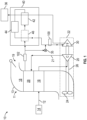
- ECS 10 environmental control system
- the ECS 10 is supplied with, for example, bleed airflow 12 from a bleed air supply system 14 of a gas turbine engine.
- the environmental control system (ECS) 10 includes a RAM air circuit 11 including a shell or duct 13 within which one or more heat exchangers are located.
- the shell 13 can receive and direct a medium, such as ram air flow 18 for example, through a ram inlet 19.
- the one or more heat exchangers 16, 28 are devices built for efficient heat transfer from one medium to another.
- Examples of the type of heat exchangers that may be used include, but are not limited to, double pipe, shell and tube, plate, plate and shell, adiabatic shell, plate fin, pillow plate, and fluid heat exchangers.
- the bleed airflow 12 is input into a primary heat exchanger 16 of the ECS 10 where the bleed airflow 12 exchanges thermal energy with a RAM airflow 18, or alternatively ambient airflow.
- the bleed airflow is then directed through a compressor 20 of an air cycle machine 22.
- the compressor 20 and fan 24 are driven by, for example, turbine 30 that shares a common shaft 26 with the compressor 20 and fan 24.
- the compressed bleed airflow 21 is directed to a secondary heat exchanger 28 where the compressed bleed airflow is cooled by thermal energy exchange with the RAM airflow 18.
- the bleed airflow 12 is then directed towards an expansion device 30 connected to the shaft 26 for primary expansion.
- the system includes at least one expansion device 30.
- the expansion device 30 will also be referred to as a turbine or the first turbine herein.
- the turbine 30 a mechanical device that includes components for performing thermodynamic work on air that leaves the compressor 20 (e.g., extracts work from or applies work to the compressed air by raising and/or lowering pressure and by raising and/or lowering temperature) and is used to drive the shaft 26 and thereby drive the fan 24 and the compressor 20.
- the compressed air is passed through a dehumidification/water removal system 40.
- This system is described as being part of the ACM for simplicity, but it shall be understood that any system 40 connected to a ACM such as ACM 22 shall be considered part of the ACM whether integrated with the ACM or implemented as a separate unit. This is applicable to all embodiments herein.
- the dehumidification system 40 includes a condenser 42, an optional reheater, and a water collector 44.
- the condenser 42 is a particular type of heat exchanger and the water collector 44 is a mechanical device that performs a process of removing water from a medium.
- the water collector 44 is a high pressure water separator that removes moisture from a medium at a highest pressure within the environmental control system 10 (e.g., downstream of the compressor 20 and ram air heat exchanger 28).
- the dehumidification system 40 further includes a reheater 46.
- the reheater 46 is another type of heat exchanger configured to increase the temperature of the air as it passes there through.
- the reheater 46 may be arranged generally upstream from the condenser 42 such that compressed air exiting secondary heat exchange 28 flows through the reheater 46 and then the condenser 42 sequentially.
- the ECS 10 can also include a bypass or economy valve (ECV) 35.
- ECV 35 When the ECV 35 is open, the air output from the ram air heat exchanger 38 has a temperature and pressure sufficient to meet the demands of the one or more loads, such as the cabin 36 for example.
- ECV 35 when ECV 35 is open, the system is said to be operating in a bypass mode. Accordingly, all or at least a portion of air output from the ram air heat exchanger 28 is configured to bypass including the dehumidification system 40 but not the turbine 30 in order to drive the compressor 20.
- a humidity sensor 100 is provided upstream of the turbine 30. As illustrated, the humidity sensor 100 is directly upstream of the turbine 30 and downstream of the ECV 35. In one embodiment, this humidity sensor 100 is the only sensor in the ECS 10. In such an embodiment, the sensor 100 can be said to be in the "turbine inlet location.” Measuring humidity in such a position allows the ECS controls to minimize the risk of rotor icing effects in the turbine 30 (e.g. reduce ACM speed or raise turbine inlet temperature if required).
- the humidity sensor 100 (or any other humidity sensor herein, e.g., sensor 102 below) can be an integrated circuit (IC) sensor that can measure one or both temperature and pressure as well. This can simplify wiring in the system and may allow for a reduction in the number of separate sensors. More importantly, advanced ECV opening logic based on measured humidity can be utilized, further optimizing system performance. Also, knowing humidity values may help in root cause failure analyses for the ECS components.
- IC integrated circuit
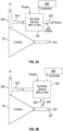
- FIGs. 2A and 2B show two different installations that may be used when measuring humidity.
- the turbine 30 is shown as having an inlet pipe 200.
- the humidity sensor 100 can divert a small portion the air provided to the turbine 30 via an inlet and an outlet.
- the inlet is shown as measuring bypass channel 202.
- the bypass channel 202 passes through the sensor 100 providing air to the sensor for measurements.
- the rate of flow through the sensor can be controlled by an exhaust orifice 205 in the exhaust 204.
- the orifice can be fixed or adjustable.
- the exhaust 204 can exhaust the air to an ambient environment. This environment can be overboard or the cabin, for example.
- the sensor 100 can receive power and can also provide data (measurements) to an ECS controller 240.
- the turbine 30 is shown as having an inlet pipe 200.
- the humidity sensor 100 can divert a small portion the air provided to the turbine 30 via a measuring bypass channel 202.
- the bypass channel 202 passes through the sensor 100 providing air to the sensor for measurements.
- the sensor 100 can receive power and can also provide data (measurements) to an ECS controller 240.
- the rate of flow through the sensor can be controlled by an exhaust orifice 205 in the exhaust 204.
- the orifice can be fixed or adjustable.
- the exhaust 204 can be connected back to the outlet 207 of the turbine 30.
- an optional second humidity sensor 102 is shown upstream of the dehumidification system 40.
- having such a second sensor can provide one more advantages.
- having two sensors in addition to the above advantages of a single sensor) can allow for performance measurements of the dehumidification system 40 and may further provide additional information for a root cause failure analysis.
- the location of sensor 102 can also provide the benefit of more accurately determining if moisture is present in the system and therefore utilize the water removal system only when required.
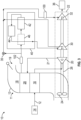
- the ECS 10 can include a pair of expansion devices 30 and 32.
- the expansion devices 30, 32 of the system 10 may, but need not be substantially identical.
- the expansion devices are turbines.
- turbine 32 can be referred to as a second turbine.
- the first and second turbines 30, 32 are both connected to the shaft 26 and, as above, are mechanical device that include components for performing thermodynamic work on air that leaves the compressor 20 (e.g., extracts work from or applies work to the compressed air by raising and/or lowering pressure and by raising and/or lowering temperature) and is used to drive the shaft 26 and thereby drive the fan 24 and the compressor 20.
- components for performing thermodynamic work on air that leaves the compressor 20 e.g., extracts work from or applies work to the compressed air by raising and/or lowering pressure and by raising and/or lowering temperature
- the dehumidification system 40 includes a condenser 42, an optional reheater, and a water collector 44.
- the condenser 42 is a particular type of heat exchanger and the water collector 44 is a mechanical device that performs a process of removing water from a medium.
- the water collector 44 is a high-pressure water separator that removes moisture from a medium at a highest pressure within the environmental control system 10 (e.g., downstream of the compressor 20 and ram air heat exchanger 28).
- the dehumidification system 40 further includes a reheater 46.
- the reheater 46 is another type of heat exchanger configured to increase the temperature of the air as it passes there through.
- the reheater 46 may be arranged generally upstream from the condenser 42 such that compressed air exiting secondary heat exchange 28 flows through the reheater 46 and then the condenser 42 sequentially.
- the air is then directed to the first turbine 30 via a first inlet tube 200' for expansion. After expansion, the air it then again directed through the condenser 42 and then into the second turbine 32 via a second inlet tube 200".
- the expanded air from the second turbine 32 can be provided to the cabin 36.
- the ECS 10 can also include a bypass or economy valve (ECV) 35.
- ECV 35 When the ECV 35 is open, the air output from the ram air heat exchanger 28 has a temperature and pressure sufficient to meet the demands of the one or more loads, such as the cabin 36 for example. Accordingly, all or at least a portion of air output from the ram air heat exchanger 28 is configured to bypass including the dehumidification system 40 and the first turbine 30 but not the second turbine 32.
- the humidity sensor 100 is provided upstream of the second turbine 32. As illustrated, the humidity sensor 100 is directly upstream of the second turbine 32 in the second inlet tube 200" and downstream of the ECV 35. As above, the system of FIG. 3 can operate in normal and bypass modes based on the position of the ECV 35.
- this humidity sensor 100 is the only sensor in the ECS 10.
- the sensor 100 can be said to be in the "second turbine inlet location" on the second inlet tube 200". Measuring humidity in such a position allows the ECS controls to minimize the risk of rotor icing effects in the turbine 32 (e.g., reduce ACM speed if required).
- sensor 100 can be arranged relative to any of turbines herein as shown in FIGs. 2A and 2B .
- FIG. 3 only a single sensor has been shown discussed. It shall be understood that one or more optional additional sensors can be provided.
- an optional second humidity sensor 102 is shown upstream of the dehumidification system 40.
- having such a second sensor can provide one more advantages.
- having two sensors in addition to the above advantages of a single sensor) can allow for performance measurements of the dehumidification system 40 be used to assess when the dehumidification system is needed and may further provide additional information in support of a root cause failure analysis of a field issue.
- first sensor 100 could be moved such that it is in the first inlet tube 200' of the first turbine 30 rather than the second inlet tube 200" of the second turbine 32.
- the dehumidification system 40 can be monitored. For example, the difference in humidity upstream of the dehumidification system 40 measured by the second humidity sensor 102 can be compared to the humidity measured by the first humidity sensor 100. The difference will show the effectiveness of dehumidification system 40 at removing humidity. Further, the values can be tracked over time to see if the effectiveness of dehumidification system 40 at removing humidity is decreasing. Such a decrease may lead to determination that the dehumidification system 40 is failing or needs maintenance or both. Such data can also be used to determine a cause of a failure of the air cycle machine.
Landscapes
- Health & Medical Sciences (AREA)
- General Health & Medical Sciences (AREA)
- Pulmonology (AREA)
- Engineering & Computer Science (AREA)
- Aviation & Aerospace Engineering (AREA)
- Drying Of Gases (AREA)
Applications Claiming Priority (1)
| Application Number | Priority Date | Filing Date | Title |
|---|---|---|---|
| US17/585,791 US12214887B2 (en) | 2022-01-27 | 2022-01-27 | Environmental control system including humidity sensor |
Publications (2)
| Publication Number | Publication Date |
|---|---|
| EP4219310A1 true EP4219310A1 (de) | 2023-08-02 |
| EP4219310B1 EP4219310B1 (de) | 2025-05-21 |
Family
ID=85132668
Family Applications (1)
| Application Number | Title | Priority Date | Filing Date |
|---|---|---|---|
| EP23153795.2A Active EP4219310B1 (de) | 2022-01-27 | 2023-01-27 | Klimaregelungssystem mit feuchtigkeitssensor |
Country Status (2)
| Country | Link |
|---|---|
| US (1) | US12214887B2 (de) |
| EP (1) | EP4219310B1 (de) |
Citations (6)
| Publication number | Priority date | Publication date | Assignee | Title |
|---|---|---|---|---|
| US6199387B1 (en) * | 1999-07-30 | 2001-03-13 | Liebherr-Aerospace Lindenberg Gmbh | Air-conditioning system for airplane cabin |
| EP1386837A1 (de) * | 2002-07-31 | 2004-02-04 | Liebherr-Aerospace Lindenberg GmbH | Flugzeugklimaanlage |
| US20150059397A1 (en) * | 2013-09-03 | 2015-03-05 | Hamilton Sundstrand Corporation | Method of operating a multi-pack enviromental control system |
| US9724979B1 (en) * | 2016-04-27 | 2017-08-08 | The Boeing Company | Model-based method to detect abnormal operations in heat exchangers |
| US20170267358A1 (en) * | 2014-09-23 | 2017-09-21 | Commercial Aircraft Corporation Of China, Ltd | Dewatering device for an air conditioning system of a plane |
| US20200180772A1 (en) * | 2018-12-06 | 2020-06-11 | The Boeing Company | Systems and methods to produce aircraft cabin supply air |
Family Cites Families (27)
| Publication number | Priority date | Publication date | Assignee | Title |
|---|---|---|---|---|
| US4836019A (en) | 1987-08-27 | 1989-06-06 | Rosemount Inc. | Compact air data sensor |
| US5046360A (en) | 1989-12-15 | 1991-09-10 | Rosemount Inc. | Aerodynamic probe internal constructions |
| US5337602A (en) | 1992-08-24 | 1994-08-16 | Gibson Michael E | Pitot static tube having accessible heating element |
| RU2157980C2 (ru) | 1997-01-28 | 2000-10-20 | Центральный аэродинамический институт им. проф. Н.Е. Жуковского | Фюзеляжный приемник воздушного давления со стойкой |
| RU2152042C1 (ru) | 1998-05-26 | 2000-06-27 | Центральный аэрогидродинамический институт им. проф. Н.Е. Жуковского | Приемник воздушного давления (варианты) |
| US6991177B2 (en) | 2004-02-06 | 2006-01-31 | Fred George | Multi-valve damper for controlling airflow and method for controlling airflow |
| FR2983964B1 (fr) | 2011-12-09 | 2014-01-10 | Thales Sa | Sonde de mesure de pression totale d'un ecoulement et procede de mise en oeuvre de la sonde |
| US9719423B2 (en) | 2012-09-04 | 2017-08-01 | General Electric Company | Inlet air chilling system with humidity control and energy recovery |
| EP2728364B1 (de) | 2012-10-31 | 2019-04-17 | Rosemount Aerospace Inc. | Eisresistente Pitot-Sonde |
| US10458342B2 (en) * | 2013-09-17 | 2019-10-29 | General Electric Company | System and method for controlling operation of a gas turbine based power plant |
| US20160304210A1 (en) | 2014-10-15 | 2016-10-20 | Rosemount Aerospace Inc. | One-piece air data probe |
| US10227139B2 (en) | 2015-03-23 | 2019-03-12 | Rosemount Aerospace Inc. | Heated air data probes |
| FR3034753B1 (fr) | 2015-04-10 | 2018-03-30 | Thales | Rechauffage d'un equipement aeronautique |
| US10089204B2 (en) | 2015-04-15 | 2018-10-02 | Hamilton Sundstrand Corporation | System level fault diagnosis for the air management system of an aircraft |
| FR3039515B1 (fr) | 2015-07-28 | 2017-09-01 | Thales Sa | Rechauffage pour equipement aeronautique |
| US9664542B2 (en) | 2015-08-20 | 2017-05-30 | Honeywell International Inc. | Systems and methods for additive manufacturing for air data probes |
| US9856027B2 (en) | 2015-10-08 | 2018-01-02 | Honeywell International Inc. | Air data probe with double helical coil heater cable |
| US9791304B2 (en) | 2015-10-21 | 2017-10-17 | Honeywell International Inc. | Air data probe heater utilizing low melting point metal |
| US9891083B2 (en) | 2016-01-08 | 2018-02-13 | Honeywell International Inc. | Probe tip for air data probe |
| US11566892B2 (en) | 2016-10-27 | 2023-01-31 | Ohio University | Air data probe |
| US10126320B2 (en) | 2017-03-13 | 2018-11-13 | Honeywell International Inc. | Arrangement of dams in air data probe |
| US11080660B2 (en) | 2017-03-20 | 2021-08-03 | The Boeing Company | Data-driven unsupervised algorithm for analyzing sensor data to detect abnormal valve operation |
| US11053010B2 (en) * | 2018-01-19 | 2021-07-06 | Hamilton Sunstrand Corporation | Aircraft environmental control system |
| US11148813B2 (en) * | 2018-04-03 | 2021-10-19 | Hamilton Sundstrand Corporation | Liquid reheater heat exchanger in an air cycle system |
| US11260346B2 (en) * | 2018-06-25 | 2022-03-01 | Hamilton Sundstrand Corporation | Inerting system |
| US10640860B2 (en) | 2018-09-13 | 2020-05-05 | Rosemount Aerospace Inc. | Laser metal deposition methodology on graphite substrates for aerospace components |
| CA3067550A1 (en) | 2019-01-17 | 2020-07-17 | Goodrich Corporation | Pitot tube |
-
2022
- 2022-01-27 US US17/585,791 patent/US12214887B2/en active Active
-
2023
- 2023-01-27 EP EP23153795.2A patent/EP4219310B1/de active Active
Patent Citations (6)
| Publication number | Priority date | Publication date | Assignee | Title |
|---|---|---|---|---|
| US6199387B1 (en) * | 1999-07-30 | 2001-03-13 | Liebherr-Aerospace Lindenberg Gmbh | Air-conditioning system for airplane cabin |
| EP1386837A1 (de) * | 2002-07-31 | 2004-02-04 | Liebherr-Aerospace Lindenberg GmbH | Flugzeugklimaanlage |
| US20150059397A1 (en) * | 2013-09-03 | 2015-03-05 | Hamilton Sundstrand Corporation | Method of operating a multi-pack enviromental control system |
| US20170267358A1 (en) * | 2014-09-23 | 2017-09-21 | Commercial Aircraft Corporation Of China, Ltd | Dewatering device for an air conditioning system of a plane |
| US9724979B1 (en) * | 2016-04-27 | 2017-08-08 | The Boeing Company | Model-based method to detect abnormal operations in heat exchangers |
| US20200180772A1 (en) * | 2018-12-06 | 2020-06-11 | The Boeing Company | Systems and methods to produce aircraft cabin supply air |
Non-Patent Citations (1)
| Title |
|---|
| CHOWDHURY SHAFAYAT HASAN ET AL: "A Methodology for the Experimental Validation of an Aircraft ECS Digital Twin Targeting System Level Diagnostics", ANNUAL CONFERENCE OF THE PHM SOCIETY, vol. 11, no. 1, 22 September 2019 (2019-09-22), XP093049521, ISSN: 2325-0178, Retrieved from the Internet <URL:https://papers.phmsociety.org/index.php/phmconf/article/download/888/phmc_19_888> [retrieved on 20230525], DOI: 10.36001/phmconf.2019.v11i1.888 * |
Also Published As
| Publication number | Publication date |
|---|---|
| EP4219310B1 (de) | 2025-05-21 |
| US20230234710A1 (en) | 2023-07-27 |
| US12214887B2 (en) | 2025-02-04 |
Similar Documents
| Publication | Publication Date | Title |
|---|---|---|
| EP3489142B1 (de) | Flugzeugumweltkontrollsystem mit zapfluftturbinen in reihe | |
| EP3514065B1 (de) | Umweltkontrollsystem für flugzeug | |
| EP3945023B1 (de) | Flugzeugklimaregelungssystem | |
| US11085673B2 (en) | Advanced environmental control system in an integrated simple cycle pack | |
| EP3549866B1 (de) | Flüssigkeitswiedererwärmer-wärmetauscher in einem luftkreislaufsystem | |
| EP2757343A1 (de) | Wärmetauscherüberbrückung für Belastung unter dem Gefrierpunkt | |
| EP3666656B1 (de) | Alternativer frischluftverdichtereinlass für klimaanlage | |
| EP3789300B1 (de) | Hybride ecs-architektur zur verringerung der triebwerkszapfluftabhängigkeit für flugzeugkabinendruck- und temperaturregelung | |
| EP4219310B1 (de) | Klimaregelungssystem mit feuchtigkeitssensor | |
| US20240410625A1 (en) | Regeneration using liquid loop of environmental control system | |
| EP4331991A1 (de) | Klimaregelungssystem mit niedrigem einlassdruck | |
| EP4725840A1 (de) | Niederdruckluftkreislauf-klimaanlagensteuersystem | |
| EP4299444A1 (de) | Umweltkontrollsystem mit geteilter regeneration | |
| EP4506254A1 (de) | Drainagesystem für ecs-wasserkollektor | |
| EP4585879A2 (de) | Funktion für einen untergefrierwärmetauscher | |
| US20250334354A1 (en) | Contoured inlet manifold for subfreezing heat exchanger | |
| EP4342798A1 (de) | Niederdruckluftkreislauf | |
| EP4509407A1 (de) | Klimatisierungs- und dampfkreislaufsystem | |
| US20260028127A1 (en) | Bleed air powered ambient aircraft environmental control system | |
| JP2012255613A (ja) | 空調装置 | |
| EP3225554B1 (de) | Flugzeugklimaanlagensystem einschliesslich einer thermoelektrischen vorrichtung |
Legal Events
| Date | Code | Title | Description |
|---|---|---|---|
| PUAI | Public reference made under article 153(3) epc to a published international application that has entered the european phase |
Free format text: ORIGINAL CODE: 0009012 |
|
| STAA | Information on the status of an ep patent application or granted ep patent |
Free format text: STATUS: THE APPLICATION HAS BEEN PUBLISHED |
|
| AK | Designated contracting states |
Kind code of ref document: A1 Designated state(s): AL AT BE BG CH CY CZ DE DK EE ES FI FR GB GR HR HU IE IS IT LI LT LU LV MC ME MK MT NL NO PL PT RO RS SE SI SK SM TR |
|
| STAA | Information on the status of an ep patent application or granted ep patent |
Free format text: STATUS: REQUEST FOR EXAMINATION WAS MADE |
|
| 17P | Request for examination filed |
Effective date: 20240202 |
|
| RBV | Designated contracting states (corrected) |
Designated state(s): AL AT BE BG CH CY CZ DE DK EE ES FI FR GB GR HR HU IE IS IT LI LT LU LV MC ME MK MT NL NO PL PT RO RS SE SI SK SM TR |
|
| GRAP | Despatch of communication of intention to grant a patent |
Free format text: ORIGINAL CODE: EPIDOSNIGR1 |
|
| STAA | Information on the status of an ep patent application or granted ep patent |
Free format text: STATUS: GRANT OF PATENT IS INTENDED |
|
| INTG | Intention to grant announced |
Effective date: 20241218 |
|
| GRAS | Grant fee paid |
Free format text: ORIGINAL CODE: EPIDOSNIGR3 |
|
| GRAA | (expected) grant |
Free format text: ORIGINAL CODE: 0009210 |
|
| STAA | Information on the status of an ep patent application or granted ep patent |
Free format text: STATUS: THE PATENT HAS BEEN GRANTED |
|
| AK | Designated contracting states |
Kind code of ref document: B1 Designated state(s): AL AT BE BG CH CY CZ DE DK EE ES FI FR GB GR HR HU IE IS IT LI LT LU LV MC ME MK MT NL NO PL PT RO RS SE SI SK SM TR |
|
| REG | Reference to a national code |
Ref country code: GB Ref legal event code: FG4D |
|
| REG | Reference to a national code |
Ref country code: CH Ref legal event code: EP |
|
| REG | Reference to a national code |
Ref country code: DE Ref legal event code: R096 Ref document number: 602023003536 Country of ref document: DE |
|
| REG | Reference to a national code |
Ref country code: IE Ref legal event code: FG4D |
|
| REG | Reference to a national code |
Ref country code: NL Ref legal event code: MP Effective date: 20250521 |
|
| PG25 | Lapsed in a contracting state [announced via postgrant information from national office to epo] |
Ref country code: FI Free format text: LAPSE BECAUSE OF FAILURE TO SUBMIT A TRANSLATION OF THE DESCRIPTION OR TO PAY THE FEE WITHIN THE PRESCRIBED TIME-LIMIT Effective date: 20250521 Ref country code: PT Free format text: LAPSE BECAUSE OF FAILURE TO SUBMIT A TRANSLATION OF THE DESCRIPTION OR TO PAY THE FEE WITHIN THE PRESCRIBED TIME-LIMIT Effective date: 20250922 Ref country code: ES Free format text: LAPSE BECAUSE OF FAILURE TO SUBMIT A TRANSLATION OF THE DESCRIPTION OR TO PAY THE FEE WITHIN THE PRESCRIBED TIME-LIMIT Effective date: 20250521 |
|
| REG | Reference to a national code |
Ref country code: LT Ref legal event code: MG9D |
|
| PG25 | Lapsed in a contracting state [announced via postgrant information from national office to epo] |
Ref country code: NO Free format text: LAPSE BECAUSE OF FAILURE TO SUBMIT A TRANSLATION OF THE DESCRIPTION OR TO PAY THE FEE WITHIN THE PRESCRIBED TIME-LIMIT Effective date: 20250821 Ref country code: GR Free format text: LAPSE BECAUSE OF FAILURE TO SUBMIT A TRANSLATION OF THE DESCRIPTION OR TO PAY THE FEE WITHIN THE PRESCRIBED TIME-LIMIT Effective date: 20250822 |
|
| PG25 | Lapsed in a contracting state [announced via postgrant information from national office to epo] |
Ref country code: PL Free format text: LAPSE BECAUSE OF FAILURE TO SUBMIT A TRANSLATION OF THE DESCRIPTION OR TO PAY THE FEE WITHIN THE PRESCRIBED TIME-LIMIT Effective date: 20250521 Ref country code: NL Free format text: LAPSE BECAUSE OF FAILURE TO SUBMIT A TRANSLATION OF THE DESCRIPTION OR TO PAY THE FEE WITHIN THE PRESCRIBED TIME-LIMIT Effective date: 20250521 |
|
| PG25 | Lapsed in a contracting state [announced via postgrant information from national office to epo] |
Ref country code: BG Free format text: LAPSE BECAUSE OF FAILURE TO SUBMIT A TRANSLATION OF THE DESCRIPTION OR TO PAY THE FEE WITHIN THE PRESCRIBED TIME-LIMIT Effective date: 20250521 |
|
| PG25 | Lapsed in a contracting state [announced via postgrant information from national office to epo] |
Ref country code: HR Free format text: LAPSE BECAUSE OF FAILURE TO SUBMIT A TRANSLATION OF THE DESCRIPTION OR TO PAY THE FEE WITHIN THE PRESCRIBED TIME-LIMIT Effective date: 20250521 |
|
| PG25 | Lapsed in a contracting state [announced via postgrant information from national office to epo] |
Ref country code: RS Free format text: LAPSE BECAUSE OF FAILURE TO SUBMIT A TRANSLATION OF THE DESCRIPTION OR TO PAY THE FEE WITHIN THE PRESCRIBED TIME-LIMIT Effective date: 20250821 |
|
| PG25 | Lapsed in a contracting state [announced via postgrant information from national office to epo] |
Ref country code: IS Free format text: LAPSE BECAUSE OF FAILURE TO SUBMIT A TRANSLATION OF THE DESCRIPTION OR TO PAY THE FEE WITHIN THE PRESCRIBED TIME-LIMIT Effective date: 20250921 |
|
| PG25 | Lapsed in a contracting state [announced via postgrant information from national office to epo] |
Ref country code: LV Free format text: LAPSE BECAUSE OF FAILURE TO SUBMIT A TRANSLATION OF THE DESCRIPTION OR TO PAY THE FEE WITHIN THE PRESCRIBED TIME-LIMIT Effective date: 20250521 |
|
| REG | Reference to a national code |
Ref country code: AT Ref legal event code: MK05 Ref document number: 1796553 Country of ref document: AT Kind code of ref document: T Effective date: 20250521 |
|
| PG25 | Lapsed in a contracting state [announced via postgrant information from national office to epo] |
Ref country code: AT Free format text: LAPSE BECAUSE OF FAILURE TO SUBMIT A TRANSLATION OF THE DESCRIPTION OR TO PAY THE FEE WITHIN THE PRESCRIBED TIME-LIMIT Effective date: 20250521 Ref country code: SM Free format text: LAPSE BECAUSE OF FAILURE TO SUBMIT A TRANSLATION OF THE DESCRIPTION OR TO PAY THE FEE WITHIN THE PRESCRIBED TIME-LIMIT Effective date: 20250521 Ref country code: DK Free format text: LAPSE BECAUSE OF FAILURE TO SUBMIT A TRANSLATION OF THE DESCRIPTION OR TO PAY THE FEE WITHIN THE PRESCRIBED TIME-LIMIT Effective date: 20250521 |
|
| PGFP | Annual fee paid to national office [announced via postgrant information from national office to epo] |
Ref country code: FR Payment date: 20251217 Year of fee payment: 4 |
|
| PG25 | Lapsed in a contracting state [announced via postgrant information from national office to epo] |
Ref country code: CZ Free format text: LAPSE BECAUSE OF FAILURE TO SUBMIT A TRANSLATION OF THE DESCRIPTION OR TO PAY THE FEE WITHIN THE PRESCRIBED TIME-LIMIT Effective date: 20250521 |
|
| PG25 | Lapsed in a contracting state [announced via postgrant information from national office to epo] |
Ref country code: EE Free format text: LAPSE BECAUSE OF FAILURE TO SUBMIT A TRANSLATION OF THE DESCRIPTION OR TO PAY THE FEE WITHIN THE PRESCRIBED TIME-LIMIT Effective date: 20250521 |
|
| PG25 | Lapsed in a contracting state [announced via postgrant information from national office to epo] |
Ref country code: SK Free format text: LAPSE BECAUSE OF FAILURE TO SUBMIT A TRANSLATION OF THE DESCRIPTION OR TO PAY THE FEE WITHIN THE PRESCRIBED TIME-LIMIT Effective date: 20250521 |
|
| PG25 | Lapsed in a contracting state [announced via postgrant information from national office to epo] |
Ref country code: IT Free format text: LAPSE BECAUSE OF FAILURE TO SUBMIT A TRANSLATION OF THE DESCRIPTION OR TO PAY THE FEE WITHIN THE PRESCRIBED TIME-LIMIT Effective date: 20250521 |
|
| REG | Reference to a national code |
Ref country code: DE Ref legal event code: R097 Ref document number: 602023003536 Country of ref document: DE |
|
| PLBE | No opposition filed within time limit |
Free format text: ORIGINAL CODE: 0009261 |
|
| STAA | Information on the status of an ep patent application or granted ep patent |
Free format text: STATUS: NO OPPOSITION FILED WITHIN TIME LIMIT |
|
| REG | Reference to a national code |
Ref country code: CH Ref legal event code: L10 Free format text: ST27 STATUS EVENT CODE: U-0-0-L10-L00 (AS PROVIDED BY THE NATIONAL OFFICE) Effective date: 20260402 |
|
| PGFP | Annual fee paid to national office [announced via postgrant information from national office to epo] |
Ref country code: DE Payment date: 20251217 Year of fee payment: 4 |
|
| 26N | No opposition filed |
Effective date: 20260224 |