EP4219316B1 - Échangeur de chaleur à conduit décalé - Google Patents
Échangeur de chaleur à conduit décalé Download PDFInfo
- Publication number
- EP4219316B1 EP4219316B1 EP23154067.5A EP23154067A EP4219316B1 EP 4219316 B1 EP4219316 B1 EP 4219316B1 EP 23154067 A EP23154067 A EP 23154067A EP 4219316 B1 EP4219316 B1 EP 4219316B1
- Authority
- EP
- European Patent Office
- Prior art keywords
- inlet duct
- heat exchanger
- sectional area
- cross
- assembly
- Prior art date
- Legal status (The legal status is an assumption and is not a legal conclusion. Google has not performed a legal analysis and makes no representation as to the accuracy of the status listed.)
- Active
Links
Images

Classifications
-
- B—PERFORMING OPERATIONS; TRANSPORTING
- B64—AIRCRAFT; AVIATION; COSMONAUTICS
- B64D—EQUIPMENT FOR FITTING IN OR TO AIRCRAFT; FLIGHT SUITS; PARACHUTES; ARRANGEMENT OR MOUNTING OF POWER PLANTS OR PROPULSION TRANSMISSIONS IN AIRCRAFT
- B64D33/00—Arrangement in aircraft of power plant parts or auxiliaries not otherwise provided for
- B64D33/02—Arrangement in aircraft of power plant parts or auxiliaries not otherwise provided for of combustion air intakes
-
- B—PERFORMING OPERATIONS; TRANSPORTING
- B64—AIRCRAFT; AVIATION; COSMONAUTICS
- B64C—AEROPLANES; HELICOPTERS
- B64C11/00—Propellers, e.g. of ducted type; Features common to propellers and rotors for rotorcraft
- B64C11/001—Shrouded propellers
-
- B—PERFORMING OPERATIONS; TRANSPORTING
- B64—AIRCRAFT; AVIATION; COSMONAUTICS
- B64D—EQUIPMENT FOR FITTING IN OR TO AIRCRAFT; FLIGHT SUITS; PARACHUTES; ARRANGEMENT OR MOUNTING OF POWER PLANTS OR PROPULSION TRANSMISSIONS IN AIRCRAFT
- B64D33/00—Arrangement in aircraft of power plant parts or auxiliaries not otherwise provided for
- B64D33/08—Arrangement in aircraft of power plant parts or auxiliaries not otherwise provided for of power plant cooling systems
- B64D33/10—Radiator arrangement
-
- F—MECHANICAL ENGINEERING; LIGHTING; HEATING; WEAPONS; BLASTING
- F02—COMBUSTION ENGINES; HOT-GAS OR COMBUSTION-PRODUCT ENGINE PLANTS
- F02C—GAS-TURBINE PLANTS; AIR INTAKES FOR JET-PROPULSION PLANTS; CONTROLLING FUEL SUPPLY IN AIR-BREATHING JET-PROPULSION PLANTS
- F02C7/00—Features, components parts, details or accessories, not provided for in, or of interest apart form groups F02C1/00 - F02C6/00; Air intakes for jet-propulsion plants
- F02C7/04—Air intakes for gas-turbine plants or jet-propulsion plants
-
- F—MECHANICAL ENGINEERING; LIGHTING; HEATING; WEAPONS; BLASTING
- F02—COMBUSTION ENGINES; HOT-GAS OR COMBUSTION-PRODUCT ENGINE PLANTS
- F02C—GAS-TURBINE PLANTS; AIR INTAKES FOR JET-PROPULSION PLANTS; CONTROLLING FUEL SUPPLY IN AIR-BREATHING JET-PROPULSION PLANTS
- F02C7/00—Features, components parts, details or accessories, not provided for in, or of interest apart form groups F02C1/00 - F02C6/00; Air intakes for jet-propulsion plants
- F02C7/12—Cooling of plants
-
- B—PERFORMING OPERATIONS; TRANSPORTING
- B64—AIRCRAFT; AVIATION; COSMONAUTICS
- B64C—AEROPLANES; HELICOPTERS
- B64C1/00—Fuselages; Constructional features common to fuselages, wings, stabilising surfaces or the like
- B64C1/16—Fuselages; Constructional features common to fuselages, wings, stabilising surfaces or the like specially adapted for mounting power plant
-
- B—PERFORMING OPERATIONS; TRANSPORTING
- B64—AIRCRAFT; AVIATION; COSMONAUTICS
- B64C—AEROPLANES; HELICOPTERS
- B64C21/00—Influencing air flow over aircraft surfaces by affecting boundary layer flow
- B64C21/01—Boundary layer ingestion [BLI] propulsion
-
- B—PERFORMING OPERATIONS; TRANSPORTING
- B64—AIRCRAFT; AVIATION; COSMONAUTICS
- B64C—AEROPLANES; HELICOPTERS
- B64C3/00—Wings
- B64C3/32—Wings specially adapted for mounting power plant
-
- B—PERFORMING OPERATIONS; TRANSPORTING
- B64—AIRCRAFT; AVIATION; COSMONAUTICS
- B64D—EQUIPMENT FOR FITTING IN OR TO AIRCRAFT; FLIGHT SUITS; PARACHUTES; ARRANGEMENT OR MOUNTING OF POWER PLANTS OR PROPULSION TRANSMISSIONS IN AIRCRAFT
- B64D33/00—Arrangement in aircraft of power plant parts or auxiliaries not otherwise provided for
- B64D33/02—Arrangement in aircraft of power plant parts or auxiliaries not otherwise provided for of combustion air intakes
- B64D2033/024—Arrangement in aircraft of power plant parts or auxiliaries not otherwise provided for of combustion air intakes comprising cooling means
-
- B—PERFORMING OPERATIONS; TRANSPORTING
- B64—AIRCRAFT; AVIATION; COSMONAUTICS
- B64D—EQUIPMENT FOR FITTING IN OR TO AIRCRAFT; FLIGHT SUITS; PARACHUTES; ARRANGEMENT OR MOUNTING OF POWER PLANTS OR PROPULSION TRANSMISSIONS IN AIRCRAFT
- B64D33/00—Arrangement in aircraft of power plant parts or auxiliaries not otherwise provided for
- B64D33/04—Arrangement in aircraft of power plant parts or auxiliaries not otherwise provided for of exhaust outlets or jet pipes
-
- F—MECHANICAL ENGINEERING; LIGHTING; HEATING; WEAPONS; BLASTING
- F05—INDEXING SCHEMES RELATING TO ENGINES OR PUMPS IN VARIOUS SUBCLASSES OF CLASSES F01-F04
- F05D—INDEXING SCHEME FOR ASPECTS RELATING TO NON-POSITIVE-DISPLACEMENT MACHINES OR ENGINES, GAS-TURBINES OR JET-PROPULSION PLANTS
- F05D2220/00—Application
- F05D2220/30—Application in turbines
- F05D2220/32—Application in turbines in gas turbines
- F05D2220/323—Application in turbines in gas turbines for aircraft propulsion, e.g. jet engines
-
- F—MECHANICAL ENGINEERING; LIGHTING; HEATING; WEAPONS; BLASTING
- F05—INDEXING SCHEMES RELATING TO ENGINES OR PUMPS IN VARIOUS SUBCLASSES OF CLASSES F01-F04
- F05D—INDEXING SCHEME FOR ASPECTS RELATING TO NON-POSITIVE-DISPLACEMENT MACHINES OR ENGINES, GAS-TURBINES OR JET-PROPULSION PLANTS
- F05D2230/00—Manufacture
- F05D2230/60—Assembly methods
-
- F—MECHANICAL ENGINEERING; LIGHTING; HEATING; WEAPONS; BLASTING
- F05—INDEXING SCHEMES RELATING TO ENGINES OR PUMPS IN VARIOUS SUBCLASSES OF CLASSES F01-F04
- F05D—INDEXING SCHEME FOR ASPECTS RELATING TO NON-POSITIVE-DISPLACEMENT MACHINES OR ENGINES, GAS-TURBINES OR JET-PROPULSION PLANTS
- F05D2250/00—Geometry
- F05D2250/30—Arrangement of components
- F05D2250/32—Arrangement of components according to their shape
- F05D2250/323—Arrangement of components according to their shape convergent
-
- F—MECHANICAL ENGINEERING; LIGHTING; HEATING; WEAPONS; BLASTING
- F05—INDEXING SCHEMES RELATING TO ENGINES OR PUMPS IN VARIOUS SUBCLASSES OF CLASSES F01-F04
- F05D—INDEXING SCHEME FOR ASPECTS RELATING TO NON-POSITIVE-DISPLACEMENT MACHINES OR ENGINES, GAS-TURBINES OR JET-PROPULSION PLANTS
- F05D2250/00—Geometry
- F05D2250/70—Shape
- F05D2250/71—Shape curved
- F05D2250/713—Shape curved inflexed
-
- F—MECHANICAL ENGINEERING; LIGHTING; HEATING; WEAPONS; BLASTING
- F05—INDEXING SCHEMES RELATING TO ENGINES OR PUMPS IN VARIOUS SUBCLASSES OF CLASSES F01-F04
- F05D—INDEXING SCHEME FOR ASPECTS RELATING TO NON-POSITIVE-DISPLACEMENT MACHINES OR ENGINES, GAS-TURBINES OR JET-PROPULSION PLANTS
- F05D2260/00—Function
- F05D2260/20—Heat transfer, e.g. cooling
- F05D2260/213—Heat transfer, e.g. cooling by the provision of a heat exchanger within the cooling circuit
-
- F—MECHANICAL ENGINEERING; LIGHTING; HEATING; WEAPONS; BLASTING
- F05—INDEXING SCHEMES RELATING TO ENGINES OR PUMPS IN VARIOUS SUBCLASSES OF CLASSES F01-F04
- F05D—INDEXING SCHEME FOR ASPECTS RELATING TO NON-POSITIVE-DISPLACEMENT MACHINES OR ENGINES, GAS-TURBINES OR JET-PROPULSION PLANTS
- F05D2260/00—Function
- F05D2260/20—Heat transfer, e.g. cooling
- F05D2260/221—Improvement of heat transfer
Definitions
- Aircraft propulsion systems use a gas turbine engine that burns carbon based fuels.
- the aircraft industry desires to significantly reduce carbon emissions produced by aircraft propulsion systems.
- Engine systems disposed within an aircraft structure provides several benefits to engine operational efficiencies.
- incorporation of propulsion systems within an airframe present challenges to existing engine architectures.
- engine systems within an aircraft structure require ducts to communicate air to a propulsion system and exhaust waste gases and airflow. The size of such ducts are constrained by the aircraft structures and therefore may not provide a desired amount of airflow for cooling.
- WO 2020/239899 A2 discloses a heat exchanger system according to the preamble of claim 1.
- US 2020/040765 A1 discloses high efficiency ducted heat exchanger systems
- US 2007/120009 A1 discloses an aircraft ram air inlet with a multi-member closure flap
- FR 747754 A discloses a heat exchanger arrangement
- US 2013/011244 A1 discloses a reconfigurable heat transfer system for a gas turbine inlet.
- a heat exchanger system for a propulsion system inlet duct as set forth in claim 1.
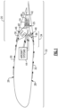
- a disclosed propulsion system embodiment 20 includes heat exchanger assemblies 46, 48 with an increased thermal transfer area without increasing duct size. The disclosed heat exchanger assemblies 46, 48 further provide desired airflow communicated to the propulsor assembly 24.
- Each of the upper inlet duct 36 and the lower inlet duct 38 provide a diverging configuration that provides desired airflow pressures and velocities.
- the limited size of the ducting can reduce the area available to provide for thermal transfer.
- the disclosed example heat exchanger assemblies 46, 48 disposed in respective inlet ducts 36, 38 include features to increase thermal transfer capabilities within the constraints of the existing airflow.
- the inlet duct assembly 34 is shown with the upper inlet duct 36 and the lower inlet duct 38 separated by a splitter 90 and merging into the common duct 40.
- the common duct 40 communicates air to the propulsor assembly 24 that is disposed within a propulsor space 86. Airflow is then exhausted through an aft heat exchanger 88 disposed in the aft duct 42.
- the upper inlet duct 36 is larger than the lower inlet duct 38.
- the disclosed upper inlet duct 36 and lower inlet duct 38 are rectangularly shaped with each having a height and width that define a cross-sectional flow area transverse to an axis extending through each duct 36, 38.
- the upper inlet duct 36 has a maximum height 82 ( Figure 3 ) and a width 62 ( Figure 2 ).
- the width 62 is uniform for the entire duct 36.
- the height diverges from the inlet toward the maximum height 82 that is disposed just prior to merging with the common duct 40.
- the maximum cross-sectional area of the upper inlet duct 36 in this example embodiment, is disposed at the location of the maximum height 82.
- the lower inlet duct 38 includes a height 84 ( Figure 3 ) and a maximum width 64 ( Figure 2 ) that is disposed just forward of the merge into the common duct 40.
- the width 64 is constant and uniform along the lower duct 38 and the height diverges from the inlet toward the maximum height 84.
- the combined forward facing cross-sectional areas 106, 108 of the upper heat exchanger assembly 46 is between 20% and 25% larger than the cross-sectional area 102.
- the combined forward facing cross-sectional areas 106, 108 of the upper heat exchanger assembly 46 is between 30% and 35% larger than the cross-sectional area 102.
- the combined forward facing cross-sectional areas of the upper heat exchanger assembly 46 is between 15% and 25% larger than the cross-sectional area 102.
- the combined forward facing cross-sectional area of the upper heat exchanger assembly 46 is between 20% and 35% larger than the cross-sectional area 102.
- the combined forward facing cross-sectional area of the upper heat exchanger assembly 46 is around 20% larger than the cross-sectional area 102.
- the combined forward facing cross-sectional area of the upper heat exchanger assembly 46 is around 30% larger than the cross-sectional area 102 of the upper duct 36 at the location corresponding with the maximum height 82.
- the larger forward facing area provided by the heat exchanger assembly 46 provides increased thermal transfer capacity without increasing duct size.
- the lower inlet duct 38 includes the lower heat exchanger assembly 48.
- the lower heat exchanger assembly 48 is scaled to fit into the smaller lower inlet duct 38 but maintains the proportionally larger front facing cross-sectional area as compared to the maximum front facing cross-sectional area located at the maximum height 84.
- the lower inlet duct 38 includes a width 64 that is uniform along the entire duct. A height of the lower inlet duct 38 increases in a direction away from an inlet opening to the maximum height 84.
- the maximum height 84 in this example is disposed at the axial location where the common inlet duct 40 begins.
- a maximum cross-sectional area 104 ( Figure 8 ) of the lower inlet duct 38 is smaller than a combined forward facing area of the lower heat exchanger 48.
- the term forward facing refers to a plane defined transverse to the longitudinal axis 76 extending through the lower inlet duct 38.
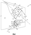
- the lower heat exchanger assembly 48 is configured in a similar manner to the upper heat exchanger assembly 46.
- a forward portion 56 is spaced forward of a first aft portion 58 and a second aft portion 60.
- a spacing 65 is disposed between the aft portions 58, 60.
- a duct 80 is provided in the axial space between the forward portion 56 and each of the aft portions 58, 60.
- the forward portion 56 includes a height 70 that is greater than the spacing 65 such that the forward portion 56 overlaps the aft portions 58, 60 when viewed along the axis 76.
- the combined forward portion front facing cross-sectional area 110 and front facing cross-sectional area 112 of each of the aft portions 58, 60 is larger than the cross-sectional area 104 ( Figure 8 ) of the lower inlet duct 38.
- the front facing cross-sectional area 112 is based on a height of 72 and a width 64 of each of the aft portions 58, 60.
- the front facing area 110 is based on the height 70 and width 64 of the forward portion 56.
- the front facing cross-sectional area provided by the lower heat exchanger assembly 48 is between 15% and 23% larger than the cross-sectional area 104.
- the combined forward facing cross-sectional area of the lower heat exchanger assembly 48 is between 15% and 18% larger than the cross-sectional area 104 of the lower duct 38. In another disclosed embodiment, the heat exchange cross-sectional area is around 15% larger than the area 104 of the lower duct 38 at the location corresponding with the maximum height 84.
- both the upper and lower heat exchanger assemblies 46, 48 provide a larger cross-sectional area than the combined duct cross-sectional areas by the same percentages as for each individual heat exchanger assembly 46, 48.
- the increased front facing cross-sectional areas provide desired thermal transfer efficiencies while maintaining duct sizing that provide desired aerodynamic properties that improve propulsive efficiencies.
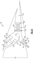
- the example propulsion system 92 includes an upper heat exchanger assembly 94 disposed in the upper inlet duct 36.
- a lower heat exchanger assembly 96 is disposed in the lower inlet duct 38.
- the upper and lower heat exchanger assemblies 94, 96 are configured in a similar offset manner to the heat exchanger assemblies 46, 48.
- the upper and lower heat exchanger assemblies 94, 96 include an additional duct feature to provide desired airflow properties to the forward heat exchanger portions 50, 56.
- the upper heat exchanger assembly 94 includes the duct 98 that directs airflow to the forward portion 50.
- the example duct 98 is converging diverging duct that increases in cross-sectional area in a direction toward the forward face of the forward portion 50.
- the lower heat exchanger assembly 96 includes duct 100 that directs airflow to the forward portion 56.
- the duct 100 is also a converging diverging duct with a cross-sectional area that increases in a direction toward the forward face of the forward portion 56.
- the converging/diverging ducts 98, 100 provide for modification of airflows that can improve thermal transfer without significantly changing airflows to the propulsor assembly 24. Moreover, the different duct geometries for the propulsor assembly 24 and the heat exchanger assemblies provide for individual tailoring of airflows to improve overall efficiencies.
- the disclosed example heat exchanger assembles provide for increased thermal efficiencies with the constraints of inlet ducts of limited size. Moreover, the disclosed heat exchanger assemblies provide for increased overall engine efficiency by providing for ingestion of boundary layer flow and also provides a tailorable propulsor configuration that is adaptable to different aircraft structures.
Landscapes
- Engineering & Computer Science (AREA)
- Chemical & Material Sciences (AREA)
- Combustion & Propulsion (AREA)
- Mechanical Engineering (AREA)
- General Engineering & Computer Science (AREA)
- Aviation & Aerospace Engineering (AREA)
- Heat-Exchange Devices With Radiators And Conduit Assemblies (AREA)
Claims (11)
- Système d'échangeur de chaleur pour conduit d'admission de système de propulsion, le système d'échangeur de chaleur comprenant :un ensemble conduit d'admission (34) comprenant un conduit d'admission (36, 40), le conduit d'admission (36, 40) comportant une section transversale (102) définie dans un plan transversal à une longueur longitudinale du conduit d'admission (36, 40) ; etun ensemble échangeur de chaleur disposé dans l'ensemble conduit d'admission (34), l'ensemble échangeur de chaleur ayant une section transversale orientée vers l'avant (110, 112) qui est plus grande que la section transversale (102) du conduit d'admission (34),caractérisé en ce que :le conduit d'admission est un conduit d'admission supérieur (36) et l'ensemble conduit d'admission (34) comporte en outre un conduit d'admission inférieur (38), le conduit d'admission inférieur (40) comportant une section transversale (104) définie dans un plan transversal à une longueur longitudinale du conduit d'admission inférieur (40) ;l'ensemble échangeur de chaleur comporte un ensemble échangeur de chaleur supérieur (46) dans le conduit d'admission supérieur (36) et un ensemble échangeur de chaleur inférieur (48) dans le conduit d'admission inférieur (38) ; etune section transversale orientée vers l'avant (110, 112) combinée de l'ensemble échangeur de chaleur supérieur (46) et de l'ensemble échangeur de chaleur inférieur (48) est plus grande que les sections transversales (110, 112) combinées du conduit d'admission supérieur (36) et du conduit d'admission inférieur (38).
- Système d'échangeur de chaleur selon la revendication 1, dans lequel le conduit d'admission supérieur (36) et le conduit d'admission inférieur (38) sont de tailles différentes.
- Échangeur de chaleur selon la revendication 2, dans lequel le conduit d'admission supérieur (36) est plus grand que le conduit d'admission inférieur (38).
- Système d'échangeur de chaleur selon une quelconque revendication précédente, dans lequel le conduit d'admission supérieur (36) et le conduit d'admission inférieur (38) sont configurés pour être en communication avec un flux de couche limite d'air le long de surfaces extérieures d'une structure d'aéronef.
- Système de propulsion d'aéronef comprenant :un fuselage d'aéronef (22) ;un ensemble propulseur (24) disposé dans le fuselage d'aéronef (22), l'ensemble propulseur (24) comportant un ventilateur de propulsion (25) rotatif autour d'un axe de ventilateur ; etle système d'échangeur de chaleur selon une quelconque revendication précédente, dans lequel le conduit d'admission (36, 40) est disposé dans le fuselage d'aéronef (22) en avant du ventilateur de propulsion (25).
- Système d'échangeur de chaleur ou système de propulsion d'aéronef selon une quelconque revendication précédente, dans lequel l'ensemble échangeur de chaleur supérieur ou inférieur comporte une partie avant (50) qui est espacée axialement en avant d'une première partie arrière (52) et d'une seconde partie arrière (54).
- Système d'échangeur de chaleur ou système de propulsion d'aéronef selon la revendication 6, dans lequel la section transversale orientée vers l'avant (110, 112) de l'ensemble échangeur de chaleur comprend une section transversale orientée vers l'avant (110, 112) combinée de la partie avant (50), de la première partie arrière (52) et de la seconde partie arrière (54).
- Système d'échangeur de chaleur ou système de propulsion d'aéronef selon la revendication 6 ou 7, dans lequel la partie avant (50) est centrée dans le conduit d'admission supérieur ou inférieur (36, 40) respectif dans une direction transversale à la longueur longitudinale, la première partie arrière (52) est disposée le long d'un premier côté dudit conduit d'admission supérieur ou inférieur (36, 40) et la seconde partie arrière (54) est disposée le long d'un second côté dudit conduit d'admission supérieur ou inférieur (36, 40).
- Système d'échangeur de chaleur ou système de propulsion d'aéronef selon l'une quelconque des revendications 6 à 8, dans lequel chacune de la partie avant (50), de la première partie arrière (52) et de la seconde partie arrière (54) est de la même taille.
- Système d'échangeur de chaleur ou système de propulsion d'aéronef selon une quelconque revendication précédente, dans lequel la section transversale orientée vers l'avant (110, 112) de l'ensemble échangeur de chaleur supérieur est entre 10 et 40 % plus grande que la section transversale (102) du conduit d'admission supérieur.
- Procédé d'assemblage du conduit d'admission (36) dans le système de propulsion d'aéronef (20) selon l'une quelconque des revendications 5 à 10, le procédé comprenant :l'assemblage du conduit d'admission supérieur (36) pour communiquer le flux d'air au ventilateur de propulsion (25) ; etle montage de l'ensemble échangeur de chaleur supérieur dans le conduit d'admission supérieur (36) en avant du ventilateur de propulsion (25), l'ensemble échangeur de chaleur supérieur étant monté de façon à inclure la section transversale orientée vers l'avant (106, 108) qui est plus grande que la section transversale (102) du conduit d'admission supérieur (36).
Applications Claiming Priority (1)
| Application Number | Priority Date | Filing Date | Title |
|---|---|---|---|
| US17/588,541 US11702984B1 (en) | 2022-01-31 | 2022-01-31 | Off-set duct heat exchanger |
Publications (2)
| Publication Number | Publication Date |
|---|---|
| EP4219316A1 EP4219316A1 (fr) | 2023-08-02 |
| EP4219316B1 true EP4219316B1 (fr) | 2025-07-02 |
Family
ID=85150170
Family Applications (1)
| Application Number | Title | Priority Date | Filing Date |
|---|---|---|---|
| EP23154067.5A Active EP4219316B1 (fr) | 2022-01-31 | 2023-01-30 | Échangeur de chaleur à conduit décalé |
Country Status (2)
| Country | Link |
|---|---|
| US (1) | US11702984B1 (fr) |
| EP (1) | EP4219316B1 (fr) |
Family Cites Families (14)
| Publication number | Priority date | Publication date | Assignee | Title |
|---|---|---|---|---|
| FR747754A (fr) * | 1932-03-12 | 1933-06-23 | Perfectionnements apportés aux échangeurs de température | |
| GB2238080B (en) * | 1987-05-26 | 1991-10-09 | Rolls Royce Plc | Improved propulsion system for an aerospace vehicle |
| JP3234898B2 (ja) * | 1999-04-16 | 2001-12-04 | 宇宙科学研究所長 | エアーブリージングエンジン用プリクーラの着霜量低減方法 |
| DE10335482B4 (de) * | 2003-08-02 | 2008-04-03 | Airbus Deutschland Gmbh | Staulufteinlass eines Flugzeuges |
| WO2008017567A1 (fr) * | 2006-08-11 | 2008-02-14 | Team Smartfish Gmbh | Admission d'air d'un moteur à réaction |
| WO2012012912A1 (fr) * | 2010-07-29 | 2012-02-02 | General Electric Company | Système de transfert thermique transformable pour entrée de turbine à gaz |
| US11506121B2 (en) * | 2016-05-26 | 2022-11-22 | Hamilton Sundstrand Corporation | Multiple nozzle configurations for a turbine of an environmental control system |
| US10676205B2 (en) | 2016-08-19 | 2020-06-09 | General Electric Company | Propulsion engine for an aircraft |
| US11105340B2 (en) | 2016-08-19 | 2021-08-31 | General Electric Company | Thermal management system for an electric propulsion engine |
| US10800539B2 (en) | 2016-08-19 | 2020-10-13 | General Electric Company | Propulsion engine for an aircraft |
| US10989071B2 (en) * | 2018-08-03 | 2021-04-27 | Meggitt (Uk) Limited | High efficiency ducted heat exchanger systems |
| US20200180771A1 (en) | 2018-12-06 | 2020-06-11 | General Electric Company | Thermal Management System for an Aircraft Including an Electric Propulsion Engine |
| GB2584331B (en) * | 2019-05-30 | 2021-10-27 | Reaction Engines Ltd | Engine |
| GB2610568A (en) * | 2021-09-08 | 2023-03-15 | Rolls Royce Plc | An improved gas turbine engine |
-
2022
- 2022-01-31 US US17/588,541 patent/US11702984B1/en active Active
-
2023
- 2023-01-30 EP EP23154067.5A patent/EP4219316B1/fr active Active
Also Published As
| Publication number | Publication date |
|---|---|
| US20230243303A1 (en) | 2023-08-03 |
| US11702984B1 (en) | 2023-07-18 |
| EP4219316A1 (fr) | 2023-08-02 |
Similar Documents
| Publication | Publication Date | Title |
|---|---|---|
| EP2604837B1 (fr) | Système permettant de diriger le flux d'air vers plusieurs caissons de ventilation | |
| EP1243782B2 (fr) | Double l'entrée d'air d'un réacteur | |
| US6216982B1 (en) | Suction device for boundary layer control in an aircraft | |
| US4892269A (en) | Spinner ducted exhaust for pusher turboprop engines | |
| US20220242583A1 (en) | Aircraft with an offset nacelle aligned with the wake of the wing | |
| EP2129579B1 (fr) | Prise d'air avec un systeme anti-givrage thermique | |
| US8690098B2 (en) | Air ejector nozzle tube for an oil heat exchanger of an aircraft engine | |
| JP6193537B2 (ja) | 流動混合通気システム | |
| EP3323730B1 (fr) | Avion comportant un turbopropulseur à montage incliné | |
| EP2071155A2 (fr) | Ensemble formant nacelle ayant des turbulateurs | |
| CN103256122B (zh) | 用于涡轮风扇发动机的密封组件和发动机舱 | |
| US5216879A (en) | Propulsion system assembly | |
| EP3816400B1 (fr) | Agencement d'aube directrice de turbine et procédé associé d'assemblage un agencement d'aube directrice de turbine | |
| US3246469A (en) | Cooling of aerofoil members | |
| US11174816B2 (en) | Bypass duct conformal heat exchanger array | |
| EP3418507B1 (fr) | Ensemble d'échappement comportant un générateur de tourbillon | |
| EP2857666B1 (fr) | Raccord de liaison de traînée et combinaison d'évent | |
| GB2165315A (en) | Improvements in or relating to hollow fluid cooled turbine blades | |
| EP3931099B1 (fr) | Configurations de système de refroidissement pour un aéronef ayant un système de propulsion hybride-électrique | |
| US8601788B2 (en) | Dual flow turboshaft engine and improved hot flow nozzle | |
| EP4219314B1 (fr) | Système de propulsion à ventilateur à couche limite canalisée | |
| EP1726811B1 (fr) | Refroidissement des volets d'une tuyère de poussée | |
| US20080203218A1 (en) | Systems And Methods For Reducing Pressure Loss Of Air Flowing From A First Area To A Second Area | |
| EP4219316B1 (fr) | Échangeur de chaleur à conduit décalé | |
| US9435210B2 (en) | Cooled turbine blade for gas turbine engine |
Legal Events
| Date | Code | Title | Description |
|---|---|---|---|
| PUAI | Public reference made under article 153(3) epc to a published international application that has entered the european phase |
Free format text: ORIGINAL CODE: 0009012 |
|
| STAA | Information on the status of an ep patent application or granted ep patent |
Free format text: STATUS: THE APPLICATION HAS BEEN PUBLISHED |
|
| AK | Designated contracting states |
Kind code of ref document: A1 Designated state(s): AL AT BE BG CH CY CZ DE DK EE ES FI FR GB GR HR HU IE IS IT LI LT LU LV MC ME MK MT NL NO PL PT RO RS SE SI SK SM TR |
|
| RAP3 | Party data changed (applicant data changed or rights of an application transferred) |
Owner name: RTX CORPORATION |
|
| STAA | Information on the status of an ep patent application or granted ep patent |
Free format text: STATUS: REQUEST FOR EXAMINATION WAS MADE |
|
| 17P | Request for examination filed |
Effective date: 20240202 |
|
| RBV | Designated contracting states (corrected) |
Designated state(s): AL AT BE BG CH CY CZ DE DK EE ES FI FR GB GR HR HU IE IS IT LI LT LU LV MC ME MK MT NL NO PL PT RO RS SE SI SK SM TR |
|
| GRAP | Despatch of communication of intention to grant a patent |
Free format text: ORIGINAL CODE: EPIDOSNIGR1 |
|
| STAA | Information on the status of an ep patent application or granted ep patent |
Free format text: STATUS: GRANT OF PATENT IS INTENDED |
|
| RIC1 | Information provided on ipc code assigned before grant |
Ipc: B64C 3/32 20060101ALN20250110BHEP Ipc: B64C 1/16 20060101ALN20250110BHEP Ipc: B64D 33/04 20060101ALN20250110BHEP Ipc: B64D 33/02 20060101ALN20250110BHEP Ipc: F04D 29/52 20060101ALI20250110BHEP Ipc: F02C 7/12 20060101ALI20250110BHEP Ipc: F02C 7/04 20060101ALI20250110BHEP Ipc: F01D 25/12 20060101ALI20250110BHEP Ipc: B64C 11/00 20060101ALI20250110BHEP Ipc: B64D 33/10 20060101AFI20250110BHEP |
|
| INTG | Intention to grant announced |
Effective date: 20250128 |
|
| GRAS | Grant fee paid |
Free format text: ORIGINAL CODE: EPIDOSNIGR3 |
|
| GRAA | (expected) grant |
Free format text: ORIGINAL CODE: 0009210 |
|
| STAA | Information on the status of an ep patent application or granted ep patent |
Free format text: STATUS: THE PATENT HAS BEEN GRANTED |
|
| AK | Designated contracting states |
Kind code of ref document: B1 Designated state(s): AL AT BE BG CH CY CZ DE DK EE ES FI FR GB GR HR HU IE IS IT LI LT LU LV MC ME MK MT NL NO PL PT RO RS SE SI SK SM TR |
|
| REG | Reference to a national code |
Ref country code: GB Ref legal event code: FG4D |
|
| REG | Reference to a national code |
Ref country code: CH Ref legal event code: EP |
|
| REG | Reference to a national code |
Ref country code: DE Ref legal event code: R096 Ref document number: 602023004373 Country of ref document: DE |
|
| REG | Reference to a national code |
Ref country code: IE Ref legal event code: FG4D |
|
| REG | Reference to a national code |
Ref country code: NL Ref legal event code: MP Effective date: 20250702 |
|
| PG25 | Lapsed in a contracting state [announced via postgrant information from national office to epo] |
Ref country code: PT Free format text: LAPSE BECAUSE OF FAILURE TO SUBMIT A TRANSLATION OF THE DESCRIPTION OR TO PAY THE FEE WITHIN THE PRESCRIBED TIME-LIMIT Effective date: 20251103 |
|
| PG25 | Lapsed in a contracting state [announced via postgrant information from national office to epo] |
Ref country code: NL Free format text: LAPSE BECAUSE OF FAILURE TO SUBMIT A TRANSLATION OF THE DESCRIPTION OR TO PAY THE FEE WITHIN THE PRESCRIBED TIME-LIMIT Effective date: 20250702 |
|
| REG | Reference to a national code |
Ref country code: AT Ref legal event code: MK05 Ref document number: 1808999 Country of ref document: AT Kind code of ref document: T Effective date: 20250702 |
|
| PG25 | Lapsed in a contracting state [announced via postgrant information from national office to epo] |
Ref country code: IS Free format text: LAPSE BECAUSE OF FAILURE TO SUBMIT A TRANSLATION OF THE DESCRIPTION OR TO PAY THE FEE WITHIN THE PRESCRIBED TIME-LIMIT Effective date: 20251102 |
|
| PG25 | Lapsed in a contracting state [announced via postgrant information from national office to epo] |
Ref country code: NO Free format text: LAPSE BECAUSE OF FAILURE TO SUBMIT A TRANSLATION OF THE DESCRIPTION OR TO PAY THE FEE WITHIN THE PRESCRIBED TIME-LIMIT Effective date: 20251002 |
|
| REG | Reference to a national code |
Ref country code: LT Ref legal event code: MG9D |
|
| PG25 | Lapsed in a contracting state [announced via postgrant information from national office to epo] |
Ref country code: AT Free format text: LAPSE BECAUSE OF FAILURE TO SUBMIT A TRANSLATION OF THE DESCRIPTION OR TO PAY THE FEE WITHIN THE PRESCRIBED TIME-LIMIT Effective date: 20250702 |
|
| PG25 | Lapsed in a contracting state [announced via postgrant information from national office to epo] |
Ref country code: FI Free format text: LAPSE BECAUSE OF FAILURE TO SUBMIT A TRANSLATION OF THE DESCRIPTION OR TO PAY THE FEE WITHIN THE PRESCRIBED TIME-LIMIT Effective date: 20250702 |
|
| PG25 | Lapsed in a contracting state [announced via postgrant information from national office to epo] |
Ref country code: HR Free format text: LAPSE BECAUSE OF FAILURE TO SUBMIT A TRANSLATION OF THE DESCRIPTION OR TO PAY THE FEE WITHIN THE PRESCRIBED TIME-LIMIT Effective date: 20250702 |
|
| PGFP | Annual fee paid to national office [announced via postgrant information from national office to epo] |
Ref country code: FR Payment date: 20251217 Year of fee payment: 4 |
|
| PG25 | Lapsed in a contracting state [announced via postgrant information from national office to epo] |
Ref country code: GR Free format text: LAPSE BECAUSE OF FAILURE TO SUBMIT A TRANSLATION OF THE DESCRIPTION OR TO PAY THE FEE WITHIN THE PRESCRIBED TIME-LIMIT Effective date: 20251003 |
|
| PG25 | Lapsed in a contracting state [announced via postgrant information from national office to epo] |
Ref country code: SE Free format text: LAPSE BECAUSE OF FAILURE TO SUBMIT A TRANSLATION OF THE DESCRIPTION OR TO PAY THE FEE WITHIN THE PRESCRIBED TIME-LIMIT Effective date: 20250702 Ref country code: CZ Free format text: LAPSE BECAUSE OF FAILURE TO SUBMIT A TRANSLATION OF THE DESCRIPTION OR TO PAY THE FEE WITHIN THE PRESCRIBED TIME-LIMIT Effective date: 20250702 |
|
| PG25 | Lapsed in a contracting state [announced via postgrant information from national office to epo] |
Ref country code: LV Free format text: LAPSE BECAUSE OF FAILURE TO SUBMIT A TRANSLATION OF THE DESCRIPTION OR TO PAY THE FEE WITHIN THE PRESCRIBED TIME-LIMIT Effective date: 20250702 |
|
| PG25 | Lapsed in a contracting state [announced via postgrant information from national office to epo] |
Ref country code: BG Free format text: LAPSE BECAUSE OF FAILURE TO SUBMIT A TRANSLATION OF THE DESCRIPTION OR TO PAY THE FEE WITHIN THE PRESCRIBED TIME-LIMIT Effective date: 20250702 Ref country code: PL Free format text: LAPSE BECAUSE OF FAILURE TO SUBMIT A TRANSLATION OF THE DESCRIPTION OR TO PAY THE FEE WITHIN THE PRESCRIBED TIME-LIMIT Effective date: 20250702 |
|
| PG25 | Lapsed in a contracting state [announced via postgrant information from national office to epo] |
Ref country code: RS Free format text: LAPSE BECAUSE OF FAILURE TO SUBMIT A TRANSLATION OF THE DESCRIPTION OR TO PAY THE FEE WITHIN THE PRESCRIBED TIME-LIMIT Effective date: 20251002 |
|
| PG25 | Lapsed in a contracting state [announced via postgrant information from national office to epo] |
Ref country code: ES Free format text: LAPSE BECAUSE OF FAILURE TO SUBMIT A TRANSLATION OF THE DESCRIPTION OR TO PAY THE FEE WITHIN THE PRESCRIBED TIME-LIMIT Effective date: 20250702 |
|
| PG25 | Lapsed in a contracting state [announced via postgrant information from national office to epo] |
Ref country code: SM Free format text: LAPSE BECAUSE OF FAILURE TO SUBMIT A TRANSLATION OF THE DESCRIPTION OR TO PAY THE FEE WITHIN THE PRESCRIBED TIME-LIMIT Effective date: 20250702 |
|
| PG25 | Lapsed in a contracting state [announced via postgrant information from national office to epo] |
Ref country code: DK Free format text: LAPSE BECAUSE OF FAILURE TO SUBMIT A TRANSLATION OF THE DESCRIPTION OR TO PAY THE FEE WITHIN THE PRESCRIBED TIME-LIMIT Effective date: 20250702 |
|
| PGFP | Annual fee paid to national office [announced via postgrant information from national office to epo] |
Ref country code: DE Payment date: 20251217 Year of fee payment: 4 |
|
| PG25 | Lapsed in a contracting state [announced via postgrant information from national office to epo] |
Ref country code: IT Free format text: LAPSE BECAUSE OF FAILURE TO SUBMIT A TRANSLATION OF THE DESCRIPTION OR TO PAY THE FEE WITHIN THE PRESCRIBED TIME-LIMIT Effective date: 20250702 |