EP4219323A1 - Siegelstation zum versiegeln von verpackungen - Google Patents
Siegelstation zum versiegeln von verpackungen Download PDFInfo
- Publication number
- EP4219323A1 EP4219323A1 EP22202078.6A EP22202078A EP4219323A1 EP 4219323 A1 EP4219323 A1 EP 4219323A1 EP 22202078 A EP22202078 A EP 22202078A EP 4219323 A1 EP4219323 A1 EP 4219323A1
- Authority
- EP
- European Patent Office
- Prior art keywords
- sealing
- distance
- lifting
- receptacle
- center
- Prior art date
- Legal status (The legal status is an assumption and is not a legal conclusion. Google has not performed a legal analysis and makes no representation as to the accuracy of the status listed.)
- Granted
Links
Images


Classifications
-
- B—PERFORMING OPERATIONS; TRANSPORTING
- B65—CONVEYING; PACKING; STORING; HANDLING THIN OR FILAMENTARY MATERIAL
- B65B—MACHINES, APPARATUS OR DEVICES FOR, OR METHODS OF, PACKAGING ARTICLES OR MATERIALS; UNPACKING
- B65B31/00—Packaging articles or materials under special atmospheric or gaseous conditions; Adding propellants to aerosol containers
- B65B31/04—Evacuating, pressurising or gasifying filled containers or wrappers by means of nozzles through which air or other gas, e.g. an inert gas, is withdrawn or supplied
- B65B31/046—Evacuating, pressurising or gasifying filled containers or wrappers by means of nozzles through which air or other gas, e.g. an inert gas, is withdrawn or supplied the nozzles co-operating, or being combined, with a device for opening or closing the container or wrapper
-
- B—PERFORMING OPERATIONS; TRANSPORTING
- B65—CONVEYING; PACKING; STORING; HANDLING THIN OR FILAMENTARY MATERIAL
- B65B—MACHINES, APPARATUS OR DEVICES FOR, OR METHODS OF, PACKAGING ARTICLES OR MATERIALS; UNPACKING
- B65B31/00—Packaging articles or materials under special atmospheric or gaseous conditions; Adding propellants to aerosol containers
- B65B31/02—Filling, closing, or filling and closing, containers or wrappers in chambers maintained under vacuum or superatmospheric pressure or containing a special atmosphere, e.g. of inert gas
- B65B31/025—Filling, closing, or filling and closing, containers or wrappers in chambers maintained under vacuum or superatmospheric pressure or containing a special atmosphere, e.g. of inert gas specially adapted for rigid or semi-rigid containers
-
- B—PERFORMING OPERATIONS; TRANSPORTING
- B65—CONVEYING; PACKING; STORING; HANDLING THIN OR FILAMENTARY MATERIAL
- B65B—MACHINES, APPARATUS OR DEVICES FOR, OR METHODS OF, PACKAGING ARTICLES OR MATERIALS; UNPACKING
- B65B31/00—Packaging articles or materials under special atmospheric or gaseous conditions; Adding propellants to aerosol containers
- B65B31/02—Filling, closing, or filling and closing, containers or wrappers in chambers maintained under vacuum or superatmospheric pressure or containing a special atmosphere, e.g. of inert gas
-
- B—PERFORMING OPERATIONS; TRANSPORTING
- B65—CONVEYING; PACKING; STORING; HANDLING THIN OR FILAMENTARY MATERIAL
- B65B—MACHINES, APPARATUS OR DEVICES FOR, OR METHODS OF, PACKAGING ARTICLES OR MATERIALS; UNPACKING
- B65B11/00—Wrapping, e.g. partially or wholly enclosing, articles or quantities of material, in strips, sheets or blanks, of flexible material
- B65B11/50—Enclosing articles, or quantities of material, by disposing contents between two sheets, e.g. pocketed sheets, and securing their opposed free margins
- B65B11/52—Enclosing articles, or quantities of material, by disposing contents between two sheets, e.g. pocketed sheets, and securing their opposed free margins one sheet being rendered plastic, e.g. by heating, and forced by fluid pressure, e.g. vacuum, into engagement with the other sheet and contents, e.g. skin-, blister-, or bubble- packaging
-
- B—PERFORMING OPERATIONS; TRANSPORTING
- B65—CONVEYING; PACKING; STORING; HANDLING THIN OR FILAMENTARY MATERIAL
- B65B—MACHINES, APPARATUS OR DEVICES FOR, OR METHODS OF, PACKAGING ARTICLES OR MATERIALS; UNPACKING
- B65B51/00—Devices for, or methods of, sealing or securing package folds or closures; Devices for gathering or twisting wrappers, or necks of bags
- B65B51/10—Applying or generating heat or pressure or combinations thereof
- B65B51/14—Applying or generating heat or pressure or combinations thereof by reciprocating or oscillating members
-
- B—PERFORMING OPERATIONS; TRANSPORTING
- B65—CONVEYING; PACKING; STORING; HANDLING THIN OR FILAMENTARY MATERIAL
- B65B—MACHINES, APPARATUS OR DEVICES FOR, OR METHODS OF, PACKAGING ARTICLES OR MATERIALS; UNPACKING
- B65B7/00—Closing containers or receptacles after filling
- B65B7/16—Closing semi-rigid or rigid containers or receptacles not deformed by, or not taking-up shape of, contents, e.g. boxes or cartons
- B65B7/28—Closing semi-rigid or rigid containers or receptacles not deformed by, or not taking-up shape of, contents, e.g. boxes or cartons by applying separate preformed closures, e.g. lids, covers
- B65B7/2842—Securing closures on containers
- B65B7/2878—Securing closures on containers by heat-sealing
Definitions
- the present invention relates to a sealing station for sealing packages according to independent claim 1 and a method for sealing a package with a sealing station according to independent claim 8.
- Sealing stations are known in principle from the prior art. These are commonly used to seal plastic packaging with product inside, such as sausage or cheese.
- the sealing stations include a lower tool in which one or more receptacles are formed, in which a lower part (or packaging tray) of a package can be accommodated.
- a plastic film is then usually placed on the lower part of the packaging as a packaging lid or film lid and the packaging is sealed by moving an upper tool of the sealing station and the lower tool towards one another and by introducing heat in the area of the film lid, in that the lower Part of the packaging and the foil lid are fused together.
- air can be evacuated from the space inside the package or the air inside the package can be replaced with a gas as sterile as possible, such as nitrogen.
- the lower tool of the sealing station usually includes an edge suction device, which can include suction openings in an area between two sealing elements, which allow air to be suctioned off in the area of the packaging.
- the film cover is pulled in the direction of the suction openings. If it rests on the suction openings, this can result in a partial blocking of the suction openings. This reduces the suction power. Ultimately, this can result in the air being sucked out of the interior of the packaging less effectively and/or result in a reduction in the throughput of the sealing station.
- the technical problem to be solved is therefore the reliability when vacuuming the interior of a package before sealing the To increase packaging and at the same time to achieve the highest possible throughput.
- this object is achieved by the sealing station according to independent claim 1 and the method for sealing a package with a sealing station according to independent claim 8 .
- Advantageous developments of the invention are included in the dependent claims.
- the sealing station according to the invention for sealing packages comprises a lower tool with at least one receptacle for a package and an upper tool, the lower tool and the upper tool being arranged so as to be movable relative to one another, the sealing station having an edge suction device with at least one suction opening for impinging on the interior of the packaging with a Vacuum and / or a gas and wherein the lower tool further comprises a lifting element for lifting a foil lid of the package
- the lower tool includes a sealing element at a distance from the center of the recording and the upper tool includes a counter-pressure element with can be brought into contact with the sealing element in order to seal a package interior from the exterior, and wherein the suction opening is arranged at a distance from the center of the receptacle that is smaller than the distance of the sealing element from the center, and wherein the lifting element is at a distance from the center the recording is arranged, which is smaller than the distance of the sealing element to the center.
- the sealing element can preferably interact with the upper tool by means of the counter-pressure element in such a way that, in particular during the sealing process, no surrounding air can penetrate into the area between the upper tool and the lower tool, so that after the evacuation and/or the ingress of gas has been completed, there is no renewed contamination until the packaging is closed.
- the arrangement of the suction opening and the lifting element within the area thus enclosed by the sealing element and the upper tool ensures reliable sterilization of the interior of the packaging.
- the lifting element does not coincide with the suction opening.
- the lifting element is intended to be physically separate from the suction opening itself and also from a structure forming the suction opening, for example arranged next to the suction opening and at a distance therefrom. With this embodiment, the suction opening can be reliably kept open in a structurally simple manner.
- the edge suction can comprise a plurality of suction openings which are arranged at a distance from the center of the receptacle which is smaller than the distance between the sealing element and the center of the receptacle, and the lifting element being arranged between two adjacent suction openings.
- the lower tool comprises an inner sealing element, which is arranged at a distance from the center of the receptacle that is smaller than the distance between the suction opening and the distance between the lifting element and the center of the receptacle.
- the inner sealing element can serve as a support surface for the actual sealing mechanism of the sealing station in order to close the packaging.
- the arrangement of the lifting element and the suction opening between this inner sealing element and the outer sealing element ensures, on the one hand, reliable suction or evacuation or admission of gas to the interior of the packaging and, on the other hand, any negative impact on the sealing process by the lifting element and/or the suction opening avoided. Together this can improve the sealing result.
- the lifting element is in the form of a pin which comprises a closed contact surface which can come into contact with a foil cover resting on it.
- This embodiment is particularly preferred for packaging with a comparatively dimensionally stable film lid, since material for the lifting elements can be saved and reliable lifting is nevertheless ensured.
- the lifting element has an elongate contact surface that can come into contact with a film cover, and wherein the contact surface has a first extent in a first direction that is greater than a second extent of the contact surface in a second direction.
- the elongate contact surface can be, for example, a rectangular contact surface or a contact surface in the shape of a segment of a circular arc. By increasing the contact area, accidental damage to the film lid can be avoided.
- the contact surface does not necessarily have to be flat, but can also represent a curved two-dimensional surface whose outer contour has a first extension in a first direction, which is greater than a second extension in a second direction. This alignment is measured in Euclidean metrics and particularly in the case of a curved contact surface, not along the contact surface and the metric defined thereby, but rather as the actual distance from opposite edges of the contact surface.
- the method according to the invention for sealing a package is carried out with a sealing station for sealing packages, the sealing station comprising a lower tool with at least one receptacle for packaging and an upper tool, wherein the lower tool and the upper tool are arranged to be movable relative to one another, wherein the sealing station comprises an edge suction device with at least one suction opening for applying a vacuum and/or a gas to the interior of the packaging and wherein the
- the lower tool further comprises a lifting element for lifting a foil lid of the packaging, the method comprising lifting the foil lid of the packaging in the receptacle by the lifting element at least partially while the interior of the packaging is subjected to a vacuum and/or a gas through the edge suction.
- This method ensures that the interior of the packaging is reliably evacuated or the air inside the packaging is replaced with a gas that is as sterile as possible.
- the lifting element at least partially causes the film lid of the packaging to be lifted in the receptacle while the interior of the packaging is subjected to a vacuum and/or a gas is to be understood in such a way that this lifting does not have to be permanent, depending on the design of the lifting element, but also can be done selectively, so that the lifting element, insofar as it is designed as an actuatable lifting element, causes the film lid to be lifted at least during a period of time over which the interior of the packaging is subjected to a vacuum and/or a gas. This does not have to be the entire time span, but can also only take place over part of this time span.
- the method includes lifting the film cover through an opening in a lower film of the packaging using the lifting element.
- the opening in the lower film can be formed, for example, by detaching part of the material of the lower film. With suitable positioning, the lifting element can then pass through the resulting free space in the lower film in order to lift the film cover.
- the opening is formed by a partial perforation of the lower film, with material of the lower film remaining in the area of the opening and being connected to the rest of the lower film. The material remaining in the area of the opening is preferably connected to the lower film on only one side, so that it can be folded by the lifting element on the one side opposite the lower film. The lifting element can then pass through the lower film in the area of the opening in order to lift the film cover.
- the upper tool and the lower tool are moved towards one another and the packaging arranged in the receptacle is sealed.
- the lower tool comprises a sealing element at a distance from the center of the receptacle and the upper tool comprises a counter-pressure element which is brought into contact with the sealing element before the edge suction is actuated in order to seal the interior of the packaging from the exterior.
- the suction opening is arranged at a distance from the center of the receptacle that is less than the distance of the sealing element from the center
- the lifting element is arranged at a distance from the center of the receptacle that is less than the distance from the sealing element to the center and the lifting element optionally not coinciding with the suction opening.
- the edge suction comprises a large number of suction openings which are arranged at a distance from the center of the receptacle which is less than the distance between the sealing element and the center of the receptacle, and wherein the lifting element is arranged between two adjacent suction openings and optionally a lifting element is arranged between each two adjacent suction openings.
- This arrangement of the one or more lifting elements makes it possible to ensure, in particular when there are a large number of suction openings, that as far as possible every suction opening is kept open. The reliability and/or the throughput when sealing the containers can thus be increased.
- the lower tool can comprise an inner sealing element, which is arranged at a distance from the center point of the receptacle that is smaller than the distance between the suction opening and the distance between the lifting element and the center point of the receptacle.
- the lifting element can be in the form of a pin which comprises a closed contact surface which comes into contact with a film cover resting on it.
- This embodiment uses as little material as possible, which reduces the costs for sealing packages.
- the lifting element has an elongate contact surface that comes into contact with a film cover, and wherein the contact surface has a first extent in a first direction that is greater than a second extent of the contact surface in a second direction.
- This embodiment also ensures that the suction openings are reliably kept open when the film cover material is flexible.
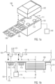
- the sealing station 100 usually comprises a lower tool 101 and an upper tool 102.
- the lower tool 101 and the upper tool 102 are usually movable relative to one another, so that, for example, the upper tool 102 moves in the direction of the lower tool 101 and away from it can be, as shown schematically by the double arrow.
- Corresponding sealing stations 100 are usually used to seal plastic packaging in which, for example, foodstuffs such as sausage products or cheese products are packaged.
- the transport device 103 can be designed as a transport belt, for example. Other embodiments are also conceivable here and the invention is not limited in this respect.
- the packaging trays with the product arranged therein are brought into contact with a cover film 112, so that the cover film is placed on these packages.
- the cover film serves at least partially as a film cover and is fused to the packaging tray by the action of heat.
- the sealing station 100 can be assigned a control unit 150, for example a computer, which controls the functions of the sealing station.
- the Fig. 1b shows a sectional view of a receptacle 111 of the lower tool 101 with 130 arranged therein and an upper tool 102 positioned relative thereto.
- the section here is in a plane perpendicular to the direction of transport of the packaging in the transport device 103 and through the center point M of the receptacle.
- the receptacle has a regular shape, for example the shape of a cylindrical depression in the lower tool. This configuration is not mandatory and other shapes, possibly even irregular ones, are also conceivable. Nevertheless, each of these shapes can be assigned a center point.
- the packaging 130 is formed from a packaging tray 131 or lower film 131 and an upper film 112 or film cover 112 positioned thereto.
- the die may include an outer sealing element 116 and an inner sealing element 113 at specific distances R 1 and R 3 .
- the outer sealing element 116 can be brought into contact with a counter-pressure element 123 of an outer part 121 of the upper tool 102, so that the space enclosed between the outer part 121 of the upper tool and the lower tool is separated from the environment as far as possible, so that there is no gas exchange between the enclosed space and the environment can take place.
- the packaging is then located in the enclosed space and is thus separated from the environment. It can be provided that (as indicated by the dashed widening of the foil cover and the lower foil) the foil cover 112 and the lower foil 131 extend beyond the outer sealing element 116 into the outside area, viewed from the center point M of the receptacle 111 .
- the outer sealing element 113 and the counter-pressure element 123 then compress the film cover 112 and the lower film 131 as completely as possible and seal the interior as gas-tight as possible, so that no undesirable contamination occurs through the entry of contaminated outside air.
- the inner sealing element 113 can preferably be brought into contact with a sealing element 124 of a sealing part 122 of the upper tool 102, between these two elements a part of the lower film 131 and a part of the film lid 112 can be accommodated, so that the sealing element 124 causes the part of the lower film 131 and the part of the film lid 112 to fuse when heat is applied.
- an edge suction device 170 with a suction opening 114 can be arranged in the lower tool at a distance R 2 from the center point of the receptacle 111, which, for example, via a vacuum pump 115 or through a gas supply 115 of the edge suction device 170, enables the exchange or suction of the enclosed space Can make gas volume in order to remove in particular the gas volume within the package or replace it with the most sterile gas possible.
- the suction opening 114 is preferably located between the sealing elements 113 and 116.
- suction opening 114 can be closed or covered by parts of the film cover material 112 when sucking off or also when gas is supplied, which can adversely affect the suction performance.
- the lower tool 101 comprises at least one lifting element in connection with the Figures 2a and 2b is described.
- the Figure 2a shows a plan view of the area of the lower tool 101 in which an edge suction device 170 with one or more suction openings 114 is arranged.
- the film cover 112 and the edge of the lower film 131 are also shown here.
- the bottom film 131 and the film cover 112 extend approximately the same distance from the center point M of the receptacle 111 .
- an opening 242 can be provided in the lower film 131 in the area of the suction openings 114 .
- This opening can be made either by partially loosening material (see Figure 2c ) of the sub-foil from the rest of the sub-foil 131 or by completely removing material of the sub-foil 131 from the area of the opening 242.
- the lower film can also only extend far enough, seen from the center M of the receptacle 111, that the lower film 131 does not rest on or in the area of the suction openings 114 or does not extend into this area.
- the lower tool 101 comprises a lifting element 240 which preferably does not coincide with the suction opening 114 of the edge suction 170. This means that neither the suction opening itself nor parts of the lower tool that form or enclose the suction opening form the lifting element 240 .
- the lifting member 240 is spaced a distance R 4 from the center point M of the receptacle 111 and is located between the sealing members 113 and 116.
- the lifting element preferably protrudes by a height h beyond the contact surface of the lower film 131 on part of the lower tool 101 in the direction of the upper tool and is arranged in such a way that part of the film cover 112 can rest on a contact surface of the lifting element 240. In this case (depending on the design of the lower film) the lifting element can pass through the opening 242 in the lower film 131 in order to be brought into contact with the film lid 112 .
- the lifting element 240 is preferably firmly connected to the lower tool 101 as a pin or spigot, so it always remains in the same position.
- the lifting element 240 is an actuatable lifting element that can be moved along the direction of the double arrow shown (i.e. towards and away from the upper tool) using a suitable drive device 241 (e.g. a motor or a control cam).
- a motor 241 it can be equipped with the in 1 control unit 150 already described, and the control unit can control the motor in such a way that the lifting element is raised, at least during a period of time during which suction opening 114 is causing gas to be suctioned from within the packaging, in such a way that film cover 112 is not on suction opening 114 rests, in particular the lifting element in the in Figure 2b shown position is positioned at a distance h from the bearing surface of the lower film 131 on the lower tool. Provision can be made for the lifting element 240 to be lowered via the drive element 241, in particular when the upper tool is moved in the direction of the lower tool in order to carry out the sealing process. It can thereby be ensured that the film cover 112 reliably comes to rest on the material of the lower film 131, even if the film cover material is rigid and can be connected to it. At the same time, the opening 242 can be closed in this way.
- the drive element 241 is designed, for example, as a control cam or generally passive drive device, a movement coupling with the movement of the upper tool (or with the relative movement of the upper tool and lower tool to one another) and here with the sealing element 124, as is described with reference to Fig. 1b was described, be provided, so that a movement of the sealing element 124 or generally of the upper tool 102 relative to the lower tool 101 is translated into a corresponding movement of the lifting element 240.
- the lifting element 240 can be made of a material that is as resistant as possible, in particular stainless steel, or can at least have an outer surface made of stainless steel.
- the contact surface of the lifting element 240 can consist of stainless steel or can comprise stainless steel.
- the lifting element can be detachably fastened in the lower tool, for example via screw or plug connections (not shown), so that the lifting element can be removed without destroying both parts of the lower tool and the lifting element itself.
- This offers the advantage that, for example, lifting elements that are shaped differently or have different lengths can also be used if this is necessary.
- Several interchangeable lifting elements 240 can be available, with individual lifting elements differing in the height h at which the bearing surface or contact surface of the lifting element is located relative to the bearing surface of the lower film 131 on the lower tool. In this way, for example, a different flexibility or rigidity of the film cover can be taken into account.
- FIG. 2c An embodiment is shown in cavalier's perspective, in which the lifting element passes through an opening 242 in the lower film 131 in the direction of the film lid 112 in order to lift it.
- the opening 242 is delimited by the material 243 of the lower film 131 .
- the material 244 can then be moved away (kinked or bent over) against the remainder of the bottom film by a lifting element 240 passing through, so that the lifting element can pass through the opening towards the film lid 112 .
- the film cover 112 is reliably lifted from the suction opening(s) 114 and cannot close them.
- a lifting element 240 is arranged between adjacent suction openings 114 .
- At least one lifting element is preferably provided for at least each receptacle in lower tool 101, so that at least one suction opening assigned to this receptacle can be protected from being unintentionally covered by the film cover by lifting element 240, which is assigned to this receptacle.
- at least one lifting element 240 is arranged between each two adjacent suction openings 114, as is shown in Figure 2a is shown. It can be provided in particular that the lifting element 240 is arranged exactly in the middle between adjacent suction openings 114 .
- FIGS. 3a to 3d show different configurations of the lifting element and in particular of the part of the lifting element that protrudes beyond the bearing surface of the lower film 131 on the lower tool 101.
- the lifting element 240 has a substantially cylindrical shape, with a body 342 of the lifting element terminating in a contact surface 341, which is preferably a closed contact surface (i.e. without a hole or other openings).
- this contact surface 341 is a flat surface, in particular a circle or an ellipse depending on the shape of the body 342. If this has an elliptical cross section, the contact surface 341 is also elliptical. If the body is cylindrical with a circular cross section, the contact surface 341 is also circular.
- FIG. 3b A similar embodiment is shown wherein the body 342 of the lifting member 240 is again configured cylindrical or elliptical in cross-section.
- the contact surface 341 is not formed as a flat surface, but as a spherical segment or ellipsoidal segment and thus has a curved surface.
- the transition to the body 342 be edge-free. This configuration offers the advantage that even in the case of strong suction power and thus a suction effect on the film cover resting on the contact surface, unintentional damage to the film cover due to sharp edges of the lifting element 240 can be avoided.
- FIG. 12 shows a further embodiment in which the lifting element is essentially shaped as a cuboid, which comprises a cuboid body 342 and a correspondingly rectangular-shaped bearing surface or contact surface 341 .
- the lifting element has a first dimension L 1 and a second dimension L 2 measured in a direction perpendicular thereto and a height h which extends beyond the bearing surface of the lower tool.
- the lifting element can have a greater extent in direction L 2 than in direction L 1 .
- the alignment of the lifting element relative to other components of the sealing station, in particular to adjacent suction openings, is not restricted. However, it can be provided that the lifting element is arranged in such a way that the extension L 2 coincides with the connecting line between two adjacent suction openings or runs parallel to it, so that in this direction a larger contact surface is available for the material of the film cover.
- the contact surface 341 is flat.
- the 3d shows an alternative embodiment, wherein the contact surface 341 is shaped as a cylinder segment with a radius of curvature R 2 .
- the lifting element and in particular the contact surface have extensions L 1 and L 2 in directions perpendicular to one another.
- the extents L 1 and L 2 are measured in Euclidean coordinates and in particular not along the metric specified by the contact surface 341 itself.
- the dimensions L 1 and L 2 can therefore to those of 3c be identical, although measured along the contact surface 341 itself, the extension of the contact surface 341 along the direction L 1 is greater compared to that 3c .
- the shape of the contact surface 341 can be chosen so that there are no edges at the transition to the body 342 of the lifting element 240 in order to avoid damage to the foil material.
Landscapes
- Engineering & Computer Science (AREA)
- Mechanical Engineering (AREA)
- Chemical & Material Sciences (AREA)
- Dispersion Chemistry (AREA)
- Physics & Mathematics (AREA)
- Fluid Mechanics (AREA)
- Vacuum Packaging (AREA)
- Closing Of Containers (AREA)
Abstract
Description
- Die vorliegende Erfindung betrifft eine Siegelstation zum Versiegeln von Verpackungen gemäß unabhängigem Anspruch 1 sowie ein Verfahren zum Versiegeln einer Verpackung mit einer Siegelstation gemäß unabhängigem Anspruch 8.
- Siegelstationen sind aus dem Stand der Technik grundsätzlich bekannt. Diese werden üblicherweise verwendet, um Kunststoffverpackungen mit darin befindlichen Produkt, wie beispielsweise Wurst oder Käse, zu versiegeln.
- Dazu umfassen die Siegelstationen ein Unterwerkzeug, in dem eine oder mehrere Aufnahmen gebildet sind, in denen ein unterer Teil (oder auch Verpackungsmulde) einer Verpackung aufgenommen werden kann. Auf den unteren Teil der Verpackung wird dann üblicherweise eine Kunststofffolie als Verpackungsdeckel oder Foliendeckel aufgelegt und durch ein Bewegen eines Oberwerkzeugs der Siegelstation und des Unterwerkzeug in Richtung aufeinander zu und durch ein Einbringen von Wärme im Bereich des Foliendeckels ein Versiegeln der Verpackung bewirkt, indem der untere Teil der Verpackung und der Foliendeckel miteinander verschmolzen werden.
- Bevor des Versiegeln erfolgt, kann ein Absaugen von Luft aus dem Raum innerhalb der Verpackung oder ein Ersetzen der Luft innerhalb der Verpackung mit einem möglichst sterilen Gas, wie beispielsweise Stickstoff, erfolgen.
- Entsprechende Einrichtungen sind insbesondere aus der
WO 2011/124548 A1 und derEP 1 908 689 A2 bekannt. Demnach umfasst üblicherweise das Unterwerkzeug der Siegelstation eine Randabsaugung, die in einem Bereich zwischen zwei Dichtelementen Absaugöffnungen umfassen kann, die ein Absaugen von Luft im Bereich der Verpackung ermöglichen. - Durch das Anlegen eines Vakuums oder allgemein einer Gasströmung wird jedoch der Foliendeckel in Richtung der Absaugöffnungen gezogen. Liegt er auf den Absaugöffnungen auf, kann ein teilweises Verschließen der Absaugöffnungen die Folge sein. Dadurch wird die Absaugleistung reduziert. Dies kann letztlich in einer weniger guten Absaugung der Luft aus dem Innenraum der Verpackung führen und/oder eine Reduktion des Durchsatzes der Siegelstation zur Folge haben.
- Ausgehend vom bekannten Stand der Technik besteht die zu lösende technische Aufgabe somit darin, die Zuverlässigkeit beim Absaugen des Innenraums einer Verpackung vor dem Siegeln der Verpackung zu erhöhen und gleichzeitig einen möglichst hohen Durchsatz zu erreichen.
- Diese Aufgabe wird erfindungsgemäß durch die Siegelstation gemäß unabhängigem Anspruch 1 und das Verfahren zum Versiegeln einer Verpackung mit einer Siegelstation gemäß unabhängigem Anspruch 8 gelöst. Vorteilhafte Weiterbildungen der Erfindung sind in den Unteransprüchen erfasst.
- Die erfindungsgemäße Siegelstation zum Versiegeln von Verpackungen umfasst ein Unterwerkzeug mit wenigstens einer Aufnahme für eine Verpackung und ein Oberwerkzeug, wobei das Unterwerkzeug und das Oberwerkzeug relativ zueinander beweglich angeordnet sind, wobei die Siegelstation eine Randabsaugung mit wenigstens einer Absaugöffnung zum Beaufschlagen des Innenraums der Verpackung mit einem Vakuum und/oder einem Gas umfasst und wobei das Unterwerkzeug weiterhin ein Anhebeelement zum Anheben eines Foliendeckels der Verpackung umfasst
- Das Anhebeelement ist dabei bevorzugt so ausgestaltet, dass er ein Anheben des Foliendeckels der Verpackung weg von dem unteren Teil der Verpackung (auch Verpackungsmulde genannt) und damit in eine Richtung weg vom Unterwerkzeug bewirken kann. Es kann vorgesehen sein, dass das Anheben ein selektives Anheben des Foliendeckels umfasst. Das selektive Anheben ist insbesondere so zu verstehen, dass der Foliendeckel nicht permanent angehoben sein muss sondern zumindest während des Beaufschlagens des Innenraums der Verpackung mit dem Vakuum und/oder einem Gas angehoben werden kann, aber zumindest während des Absenkens des Oberwerkzeugs und des Siegelvorgangs zum Versiegeln der Verpackung abgesenkt werden kann, sodass der Foliendeckel auf der Verpackungsmulde aufliegt und ein Siegeln der gesamten Verpackung bewirkt werden kann.
- Durch das Anheben des Foliendeckels der Verpackung zumindest während des Beaufschlagens des Innenraums der Verpackung mit einem Vakuum und/oder einem Gas wird ein Offenhalten der wenigstens einen Absaugöffnung gewährleistet. Damit wird zuverlässig ein Absaugen der Luft aus der Verpackung gewährleistet. Gleichzeitig kann so erreicht werden, dass die Absaugleistung verglichen mit Vorrichtungen aus dem Stand der Technik noch erhöht werden kann, ohne dass es zu einem zumindest teilweisen Verschließen der Absaugöffnungen kommt.
- Es kann vorgesehen sein, dass das Unterwerkzeug ein Dichtelement in einem Abstand zum Mittelpunkt der Aufnahme umfasst und das Oberwerkzeug ein Gegendruckelement umfasst, das mit dem Dichtelement in Anlage gebracht werden kann, um einen Verpackungsinnenraum gegenüber dem Außenraum abzudichten, und wobei die Absaugöffnung in einem Abstand zum Mittelpunkt der Aufnahme angeordnet ist, der kleiner ist als der Abstand des Dichtelements zum Mittelpunkt, und wobei das Anhebeelement in einem Abstand zum Mittelpunkt der Aufnahme angeordnet ist, der kleiner ist als der Abstand des Dichtelements zum Mittelpunkt.
- Das Dichtelement kann bevorzugt mit dem Oberwerkzeug derart vermittels des Gegendruckelements zusammenwirken, dass insbesondere während des Siegelvorgangs keine umgebende Luft in den Bereich zwischen Oberwerkzeug und Unterwerkzeug eindringen kann, sodass nach Abschluss des Evakuierens und/oder des Eindringens von Gas keine erneute Kontamination erfolgt, bis die Verpackung verschlossen ist. Durch die Anordnung der Absaugöffnung und des Anhebeelements innerhalb des so von dem Dichtelement und dem Oberwerkzeug eingeschlossenen Bereichs wird ein zuverlässiges Sterilisieren des Verpackungsinnenraums gewährleistet.
- In einer Ausführungsform fällt Anhebeelement nicht mit der Absaugöffnung zusammen. Im Sinne dieser Ausführungsform ist das Anhebeelement als physisch separat von der Absaug-öffnung selbst und auch einer die Absaugöffnung bildenden Struktur vorgesehen, beispielsweise neben der Absaugöffnung und in einem Abstand dazu angeordnet. Mit dieser Ausführungsform kann auf konstruktiv einfache Weise ein zuverlässiges Offenhalten der Absaugöffnung realisiert werden.
- Ferner kann die Randabsaugung eine Vielzahl von Absaugöffnungen umfassen, die in einem Abstand zum Mittelpunkt der Aufnahme angeordnet sind, der kleiner ist als der Abstand des Dichtelements zum Mittelpunkt der Aufnahme, und wobei das Anhebeelement zwischen zwei benachbarten Absaugöffnungen angeordnet ist.
- Mit dieser Ausführungsform kann durch Verwendung eines einzelnen Anhebeelements ein Offenhalten von wenigstens zwei Absaugöffnungen gewährleistet werden, was die notwendige Anzahl der Anhebeelemente reduzieren kann und gleichzeitig ein zuverlässiges Offenhalten der Absaugöffnung bewirkt.
- In einer Weiterbildung dieser Ausführungsform ist zwischen jeweils zwei benachbarten Absaugöffnungen ein Anhebeelement angeordnet. In dieser Ausführungsform wechseln sich Anhebeelement und Absaugöffnung jeweils ab, sodass alternierend ein Anhebeelement und eine Absaugöffnung (beispielsweise gesehen entlang der Transportrichtung der Verpackungen) vorgesehen sind. Hierdurch kann jede der Absaugöffnungen offengehalten werden, sodass etwa auch beim Vorsehen mehrerer Aufnahmen und einer Vielzahl von Absaugöffnungen die Absaugleistung und damit auch der Durchsatz hoch sein kann.
- In einer Ausführungsform ist vorgesehen, dass das Unterwerkzeug ein inneres Dichtelement umfasst, das in einem Abstand zum Mittelpunkt der Aufnahme angeordnet ist, der kleiner ist als der Abstand der Absaugöffnung und der Abstand des Anhebeelements zum Mittelpunkt der Aufnahme.
- Das innere Dichtelement kann als Auflagefläche für den eigentlichen Siegelmechanismus der Siegelstation dienen, um die Verpackung zu verschließen. Durch die Anordnung des Anhebeelements und der Absaugöffnung zwischen diesem inneren Dichtelement und dem äußeren Dichtelement wird zum einen ein zuverlässiges Absaugen bzw. Evakuieren oder Beaufschlagen des Innenraums der Verpackung mit Gas gewährleistet und zum anderen eine etwaige negative Beeinträchtigung des Siegelvorgangs durch das Anhebeelement und/oder die Absaugöffnung vermieden. Zusammen kann dies das Siegelergebnis verbessern.
- In einer weiteren Ausführungsform ist das Anhebeelement als Stift ausgebildet, der eine geschlossene Kontaktfläche umfasst, die mit einem darauf aufliegenden Foliendeckel in Kontakt treten kann. Diese Ausführungsform ist insbesondere für Verpackungen mit einem vergleichsweise formstabilen Foliendeckel bevorzugt, da hiermit Material für die Anhebeelemente eingespart werden kann und dennoch ein zuverlässiges Anheben gewährleistet wird.
- Alternativ dazu kann vorgesehen sein, dass das Anhebeelement eine längliche Kontaktfläche aufweist, die mit einem Foliendeckel in Kontakt treten kann, und wobei die Kontaktfläche eine erste Ausdehnung in einer ersten Richtung aufweist, die größer ist als eine zweite Ausdehnung der Kontaktfläche in einer zweiten Richtung.
- Die längliche Kontaktfläche kann beispielsweise eine rechteckige Kontaktfläche oder eine kreisbogensegmentförmige Kontaktfläche sein. Durch Vergrößerung der Kontaktfläche können unbeabsichtigte Beschädigungen des Foliendeckels vermieden werden. Die Kontaktfläche muss im Sinne dieser Ausführungsform nicht notwendig eben sein, sondern kann auch eine gekrümmte zweidimensionale Oberfläche darstellen, deren äußere Kontur jedoch eine erste Ausdehnung in einer ersten Richtung aufweist, die größer ist als eine zweite Ausdehnung in einer zweiten Richtung. Gemessen wird diese Ausrichtung in euklidischer Metrik und insbesondere bei gekrümmter Kontaktfläche nicht entlang der Kontaktfläche und der dadurch definierten Metrik sondern als tatsächlicher Abstand von gegenüberliegenden Kanten der Kontaktfläche.
- Das erfindungsgemäße Verfahren zum Versiegeln einer Verpackung wird mit einer Siegelstation zum Versiegeln von Verpackungen durchgeführt, die Siegelstation umfassend ein Unterwerkzeug mit wenigstens einer Aufnahme für eine Verpackung und ein Oberwerkzeug, wobei das Unterwerkzeug und das Oberwerkzeug relativ zueinander beweglich angeordnet sind, wobei die Siegelstation eine Randabsaugung mit wenigstens einer Absaugöffnung zum Beaufschlagen des Innenraums der Verpackung mit einem Vakuum und/oder einem Gas umfasst und wobei das Unterwerkzeug weiterhin ein Anhebeelement zum Anheben eines Foliendeckels der Verpackung umfasst, wobei das Verfahren ein Anheben des Foliendeckels der Verpackung in der Aufnahme durch das Anhebeelement zumindest teilweise während des Beaufschlagens des Innenraums der Verpackung mit einem Vakuum und/oder einem Gas durch die Randabsaugung umfasst.
- Dieses Verfahren gewährleistet ein zuverlässiges Absaugen des Innenraums der Verpackung bzw. Ersetzen der Luft innerhalb der Verpackung durch ein möglich steriles Gas.
- Dass das Anhebeelement zumindest teilweise während des Beaufschlagens des Innenraums der Verpackung mit einem Vakuum und/oder einem Gas ein Anheben des Foliendeckels der Verpackung in der Aufnahme bewirkt ist so zu verstehen, dass dieses Anheben abhängig von der Ausgestaltung des Anhebeelements nicht permanent erfolgen muss sondern auch selektiv erfolgen kann, sodass das Anhebeelement, soweit es als betätigbares Anhebeelement ausgebildet ist, ein Anheben des Foliendeckels zumindest während einer Zeitspanne bewirkt, über die sich das Beaufschlagen des Innenraums der Verpackung mit einem Vakuum und/oder einem Gas erstreckt. Dies muss nicht die gesamte Zeitspanne sein, sondern kann auch nur über einen Teil dieser Zeitspanne erfolgen.
- Insbesondere kann vorgesehen sein, dass das Verfahren ein Anheben des Foliendeckels durch eine Öffnung in einer Unterfolie der Verpackung hindurch durch das Anhebeelement umfasst. In dieser Ausführungsform kann die Öffnung in der Unterfolie beispielsweise durch Herauslösen eines Teils des Materials der Unterfolie gebildet werden. Durch die so entstehende freie Stelle in der Unterfolie kann dann bei geeigneter Positionierung das Anhebeelement hindurchtreten, um den Foliendeckel anzuheben. Alternativ kann auch vorgesehen sein, dass die Öffnung durch eine teilweise Perforation der Unterfolie gebildet wird, wobei Material der Unterfolie im Bereich der Öffnung verbleibt und mit der übrigen Unterfolie verbunden ist. Bevorzugt ist das im Bereich der Öffnung verbleibende Material an nur einer Seite mit der Unterfolie verbunden, sodass es durch das Anhebeelement an der einen Seite gegenüber der Unterfolie geknickt werden kann. Das Anhebeelement kann dann im Bereich der Öffnung durch die Unterfolie hindurchtreten, um den Foliendeckel anzuheben.
- Mit dieser Ausführungsform kann ein zuverlässiges Absaugen auch bei deckungsgleichen Foliendeckeln und Unterfolien, die gemeinsam die Verpackung bilden, gewährleistet werden.
- Es kann vorgesehen sein, dass nach der Beaufschlagung des Innenraums der Verpackung mit einem Vakuum und/oder einem Gas das Oberwerkzeug und das Unterwerkzeug aufeinander zu bewegt werden und die in der Aufnahme angeordnete Verpackung versiegelt wird.
- In einer Ausführungsform ist weiterhin vorgesehen, dass das Unterwerkzeug ein Dichtelement in einem Abstand zum Mittelpunkt der Aufnahme umfasst und das Oberwerkzeug ein Gegendruckelement umfasst, das mit dem Dichtelement in Anlage gebracht wird, bevor die Randabsaugung betätigt wird, um einen Verpackungsinnenraum gegenüber dem Außenraum abzudichten, und wobei die Absaugöffnung in einem Abstand zum Mittelpunkt der Aufnahme angeordnet ist, der kleiner ist als der Abstand des Dichtelements zum Mittelpunkt, und wobei das Anhebeelement in einem Abstand zum Mittelpunkt der Aufnahme angeordnet ist, der kleiner ist als der Abstand des Dichtelements zum Mittelpunkt und wobei das Anhebeelement optional nicht mit der Absaugöffnung zusammenfällt. Durch diese relative Anordnung wird während des Absaugens sichergestellt, dass keine Außenluft in den Verpackungsinnenraum eindringen kann.
- In einer Weiterbildung dieser Ausführungsform umfasst die Randabsaugung eine Vielzahl von Absaugöffnungen, die in einem Abstand zum Mittelpunkt der Aufnahme angeordnet sind, der kleiner ist als der Abstand des Dichtelements zum Mittelpunkt der Aufnahme, und wobei das Anhebeelement zwischen zwei benachbarten Absaugöffnungen angeordnet ist und wobei optional zwischen jeweils zwei benachbarten Absaugöffnungen ein Anhebeelement angeordnet ist.
- Durch diese Anordnung des einen oder der mehreren Anhebeelemente kann insbesondere bei einer Vielzahl von Absaugöffnungen sichergestellt werden, dass möglichst jede Absaugöffnung offengehalten wird. Die Zuverlässigkeit und/oder der Durchsatz beim Versiegeln der Behälter können somit erhöht werden.
- Weiterhin kann das Unterwerkzeug ein inneres Dichtelement umfassen, das in einem Abstand zum Mittelpunkt der Aufnahme angeordnet ist, der kleiner ist als der Abstand der Absaugöffnung und der Abstand des Anhebeelements zum Mittelpunkt der Aufnahme. Durch diese Ausgestaltung wird ein zuverlässiges Versiegeln der Verpackungen ohne eventuell störenden Einfluss der Absaugöffnung und/oder des Anhebeelements bewirkt.
- Es kann auch vorgesehen sein, dass das Anhebeelement als Stift ausgebildet ist, der eine geschlossene Kontaktfläche umfasst, die mit einem darauf aufliegenden Foliendeckel in Kontakt tritt. Diese Ausführungsform hat möglichst geringen Materialaufwand, was die Kosten für das Versiegeln von Verpackungen verringert.
- Alternativ dazu kann vorgesehen sein, dass das Anhebeelement eine längliche Kontaktfläche aufweist, die mit einem Foliendeckel in Kontakt tritt, und wobei die Kontaktfläche eine erste Ausdehnung in einer ersten Richtung aufweist, die größer ist als eine zweite Ausdehnung der Kontaktfläche in einer zweiten Richtung. Mit dieser Ausführungsform wird auch ein zuverlässiges Offenhalten der Absaugöffnungen bei flexiblem Material der Foliendeckel gewährleistet.
-
- Fig.1a und b
- zeigen eine Siegelstation gemäß einer Ausführungsform;
- Fig. 2a bis c
- zeigen eine Draufsicht und eine Seitenansicht eines Teils einer Siegelstation gemäß einer Ausführungsform sowie ein Anheben des Foliendeckels einer Verpackung;
- Fig. 3a bis 3d
- zeigen unterschiedliche Ausführungsformen eines Anhebeelements.
-
Fig. 1 zeigt eine Siegelstation 100 gemäß einer Ausführungsform der vorliegenden Offenbarung. Die Siegelstation 100 umfasst, wie aus dem Stand der Technik bekannt, üblicherweise ein Unterwerkzeug 101 und ein Oberwerkzeug 102. Das Unterwerkzeug 101 und das Oberwerkzeug 102 sind üblicherweise relativ zueinander bewegbar, sodass beispielsweise das Oberwerkzeug 102 in Richtung des Unterwerkzeugs 101 und von diesem weg bewegt werden kann, wie dies durch den Doppelpfeil schematisch gezeigt ist. - Entsprechende Siegelstationen 100 werden üblicherweise verwendet, um Kunststoffverpackungen, in denen beispielsweise Lebensmittel, wie Wurstwaren oder Käsewaren verpackt werden, zu versiegeln.
- Dafür werden noch unverschlossene Unterseiten der Verpackungen 130, auch als Verpackungsmulden oder Unterfolie 131 (siehe
Fig. 1b ) bezeichnet, mit darin eingefülltem Produkt beispielsweise über die hier nur schematisch dargestellte Transporteinrichtung 103 wenigstens einer Aufnahme 111 in dem Unterwerkzeug 101 zugeführt. Die Transporteinrichtung 103 kann beispielsweise als Transportband ausgebildet sein. Auch andere Ausführungsformen sind hier denkbar und die Erfindung ist diesbezüglich nicht beschränkt. - Bekanntermaßen werden die Verpackungsmulden mit dem darin angeordneten Produkt mit einer Deckfolie 112 in Anlage gebracht, sodass die Deckfolie auf diese Verpackungen aufgelegt wird. Die Deckfolie dient zumindest teilweise als Foliendeckel und wird durch Wärmeeinwirkung mit der Verpackungsmulde verschmolzen. Der Siegelstation 100 kann eine Steuereinheit 150, beispielsweise ein Computer, zugeordnet sein, der die Funktionen der Siegelstation steuert.
- Die
Fig. 1b zeigt eine Schnittansicht einer Aufnahme 111 des Unterwerkzeugs 101 mit darin angeordneter 130 und ein relativ dazu positioniertes Oberwerkzeug 102. Der Schnitt erfolgt hier in einer Ebene senkrecht zur Transportrichtung der Verpackungen in der Transporteinrichtung 103 und durch den Mittelpunkt M der Aufnahme. In der hier dargestellten Ausführungsform hat die Aufnahme eine regelmäßige Form, beispielsweise die Form einer zylindrischen Vertiefung in dem Unterwergzeug. Diese Ausgestaltung ist so nicht zwingend und auch andere, ggf. auch unregelmäßige Formen sind denkbar. Dennoch kann jeder dieser Formen ein Mittelpunkt zugeordnet werden. - Wie dargestellt, wird die Verpackung 130 aus einer Verpackungsmulde 131 bzw. Unterfolie 131 und einer dazu positionierten Oberfolie 112 bzw. Foliendeckel 112 gebildet.
- Wie zu erkennen, kann das Unterwerkzeug in bestimmten Abständen R1 und R3 ein äußeres Dichtelement 116 und ein inneres Dichtelement 113 umfassen.
- Das äußere Dichtelement 116 kann dabei mit einem Gegendruckelement 123 eines äußeren Teils 121 des Oberwerkzeugs 102 in Anlage gebracht werden, sodass der zwischen dem äußeren Teil 121 des Oberwerkzeugs und dem Unterwerkzeug eingeschlossener Raum möglichst von der Umgebung abgetrennt ist, sodass kein Gasaustausch zwischen dem eingeschlossenen Raum und der Umgebung stattfinden kann. In dem eingeschlossenen Raum befindet sich dann die Verpackung und ist somit von der Umgebung abgetrennt. Es kann vorgesehen sein, dass sich (wie durch die gestrichelte Erweiterung des Foliendeckels und der Unterfolie angedeutet) der Foliendeckel 112 und die Unterfolie 131 vom Mittelpunkt M der Aufnahme 111 aus gesehen über das äußere Dichtelement 116 hinaus in den Außenbereich erstrecken. In diesem Fall werden durch das äußere Dichtelement 113 und das Gegendruckelement 123 dann der Foliendeckel 112 und die Unterfolie 131 möglichst vollständig zusammengedrückt und der Innenraum möglichst gasdicht verschlossen, sodass keine unerwünschte Kontamination durch Eintritt etwa kontaminierten Außenluft erfolgt.
- Das innere Dichtelement 113 kann bevorzugt mit einem Siegelelement 124 eines Siegelteils 122 des Oberwerkzeugs 102 in Anlage gebracht werden, wobei zwischen diesen beiden Elementen ein Teil der Unterfolie 131 und ein Teil des Foliendeckels 112 aufgenommen werden kann, sodass bei Wärmeeinwirkung durch das Siegelelement 124 ein Verschmelzen des Teils der Unterfolie 131 und des Teils des Foliendeckels 112 erfolgt.
- Bevor oder während das Siegeln der Verpackung durch Verbinden des Foliendeckels 112 und Unterfolie 131, wie eben beschrieben, erfolgt, ist es bekannt, den Innenraum der Verpackung 130 entweder zu evakuieren und/oder mit einem möglichst sterilen Gas, beispielsweise Stickstoff die darin befindliche Luft zu verdrängen. Dazu kann in dem Unterwerkzeug, in einem Abstand R2 vom Mittelpunkt der Aufnahme 111 eine Randabsaugung 170 mit einer Absaugöffnung 114 angeordnet sein, die beispielsweise über eine Vakuumpumpe 115 oder durch eine Gaszufuhr 115 der Randabsaugung 170 einen Austausch oder ein Absaugen des im eingeschlossenen Raum befindlichen Gasvolumens vornehmen kann, um so insbesondere das Gasvolumen innerhalb der Verpackung zu entfernen oder durch das möglichst sterile Gas auszutauschen. Bevorzugt befindet sich die Absaugöffnung 114 dabei zwischen den Dichtelementen 113 und 116.
- Dieses Vorgehen ist ganz grundsätzlich aus dem Stand der Technik bekannt. Es birgt jedoch den Nachteil, dass beim Absaugen oder auch beim Zuführen von Gas die Absaugöffnung 114 durch Teile des Foliendeckelmaterials 112 verschlossen bzw. bedeckt werden kann, was die Absaugleistung negativ beeinträchtigen kann.
- Erfindungsgemäß umfasst daher das Unterwerkzeug 101 wenigstens ein Anhebeelement, das im Zusammenhang mit den
Fig. 2a und 2b beschrieben wird. - Die
Fig. 2a zeigt eine Draufsicht auf den Bereich des Unterwerkzeugs 101, in dem eine Randabsaugung 170 mit einer oder mehreren Absaugöffnungen 114 angeordnet ist. Der Foliendeckel 112 sowie die Kante der Unterfolie 131 sind hier ebenfalls dargestellt. In der hier gezeigten Ansicht erstrecken sich Unterfolie 131 und Foliendeckel 112 in etwa gleich weit vom Mittelpunkt M der Aufnahme 111 weg. In diesem Fall (wie hier ebenfalls gestrichelt dargestellt) im Bereich der Absaugöffnungen 114 eine Öffnung 242 in der Unterfolie 131 vorgesehen sein. Diese Öffnung kann entweder durch teilweises Lösen von Material (sieheFig. 2c ) der Unterfolie von dem Rest der Unterfolie 131 oder durch vollständiges Entfernen von Material der Unterfolie 131 aus dem Bereich der Öffnung 242 gebildet werden. Alternativ zu der hier dargestellten Ausführungsform kann sich die Unterfolie auch gesehen vom Mittelpunkt M der Aufnahme 111 nur so weit erstrecken, dass die Unterfolie 131 nicht auf oder im Bereich der Absaugöffnungen 114 aufliegt bzw. sich nicht in diesen Bereich erstreckt. - Erfindungsgemäß umfasst das Unterwerkzeug 101 ein Anhebeelement 240, das bevorzugt nicht mit der Absaugöffnung 114 der Randabsaugung 170 zusammenfällt. Dies bedeutet, dass weder die Absaugöffnung selbst noch Teile des Unterwerkzeugs, die die Absaugöffnung bilden oder einschließen, das Anhebeelement 240 bildet.
- Wie in
Fig. 2b dargestellt, ist das Anhebeelement 240 in einem Abstand R4 vom Mittelpunkt M der Aufnahme 111 entfernt und zwischen den Dichtelementen 113 und 116 angeordnet. Das Anhebeelement ragt bevorzugt um eine Höhe h über die Auflagefläche der Unterfolie 131 auf einem Teil des Unterwerkzeugs 101 hinaus in Richtung des Oberwerkzeugs und ist so angeordnet, dass ein Teil des Foliendeckels 112 auf einer Kontaktfläche des Anhebeelements 240 aufliegen kann. Dabei kann (abhängig von der Ausgestaltung der Unterfolie) das Anhebeelement durch die Öffnung 242 in der Unterfolie 131 hindurchtreten, um mit dem Foliendeckel 112 in Anlage gebracht zu werden. - Hierdurch wird gewährleistet, dass der Foliendeckel 112 nicht auf der Absaugöffnung 114, wie sie insbesondere in
Fig. 2a gezeigt ist, aufliegen kann, sondern etwa in der Höhe h beabstandet von der Absaugöffnung 114 bleibt, auch wenn die Absaugöffnung ein Absaugen des Gasvolumens innerhalb der Verpackung bewirkt. - In der hier dargestellten Ausführungsform ist das Anhebeelement 240 bevorzugt als Stift oder Zapfen fest mit dem Unterwerkzeug 101 verbunden, verbleibt also stets in derselben Position. Es kann jedoch auch vorgesehen sein, dass das Anhebeelement 240 ein betätigbares Anhebeelement ist, das etwa über eine geeignete Antriebseinrichtung 241 (beispielsweise ein Motor oder eine Steuerkurve) entlang der dargestellten Doppelpfeilrichtung (also auf das Oberwerkzeug zu und von diesem weg) bewegt werden kann. Ist ein Motor 241 vorgesehen, so kann dieser mit der in
Fig. 1 bereits beschriebenen Steuereinheit 150 verbunden sein und die Steuereinheit kann den Motor so ansteuern, dass das Anhebeelement zumindest während eines Zeitraums, während dem die Absaugöffnung 114 ein Absaugen von Gas innerhalb der Verpackung bewirkt, derart angehoben ist, dass der Foliendeckel 112 nicht auf der Absaugöffnung 114 aufliegt, insbesondere das Anhebeelement in der inFig. 2b dargestellten Position in einem Abstand h von der Auflagefläche der Unterfolie 131 auf dem Unterwerkzeug positioniert ist. Es kann vorgesehen sein, dass ein Absenken des Anhebeelements 240 über das Antriebselement 241 bewirkt wird, insbesondere wenn das Oberwerkzeug in Richtung des Unterwerkzeugs bewegt wird, um den Siegelvorgang durchzuführen. Dadurch kann sichergestellt werden, dass der Foliendeckel 112 etwa auch bei starrem Foliendeckelmaterial zuverlässig auf dem Material der Unterfolie 131 zum Liegen kommt und mit diesem verbunden werden kann. Gleichzeitig kann so die Öffnung 242 verschlossen werden. - Ist das Antriebselement 241 beispielsweise als Steuerkurve oder allgemein passive Antriebseinrichtung ausgebildet, kann insbesondere eine Bewegungskopplung mit der Bewegung des Oberwerkzeugs (oder mit der relativen Bewegung von Oberwerkzeug und Unterwerkzeug zueinander) und hier mit dem Siegelelement 124, wie es mit Bezug auf
Fig. 1b beschrieben wurde, vorgesehen sein, sodass eine Bewegung des Siegelelements 124 oder allgemein des Oberwerkzeugs 102 relativ zum Unterwerkzeug 101 in eine entsprechende Bewegung des Anhebeelements 240 übersetzt wird. - Unabhängig von seiner Ausgestaltung kann das Anhebeelement 240 aus einem möglichst widerstandsfähigen Material, insbesondere Edelstahl gefertigt sein oder zumindest eine äußere Oberfläche aus Edelstahl umfassen. Insbesondere kann die Kontaktfläche des Anhebeelements 240 aus Edelstahl bestehen oder Edelstahl umfassen.
- Das Anhebeelement kann in dem Unterwerkzeug lösbar befestigt sein, beispielsweise über Schraub- oder Steckverbindungen (nicht gezeigt), sodass ein Herausnehmen des Anhebeelements zerstörungsfrei sowohl mit Hinblick auf Teile des Unterwerkzeugs als auch das Anhebeelement selbst möglich ist. Dies bietet den Vorteil, dass beispielsweise auch unterschiedlich geformte oder unterschiedlich lange Anhebeelemente eingesetzt werden können, falls dies notwendig ist. So können mehrere austauschbare Anhebeelemente 240 zur Verfügung stehen, wobei einzelne Anhebeelemente sich durch die Höhe h, in der sich die Auflagefläche oder Kontaktfläche des Anhebeelements jeweils relativ zur Auflagefläche der Unterfolie 131 auf dem Unterwerkzeug befindet, unterscheiden. Hiermit kann beispielsweise eine unterschiedliche Flexibilität oder Steifigkeit des Foliendeckels berücksichtigt werden.
- In
Fig. 2c ist eine Ausführungsform in Kavaliersperspektive gezeigt, bei der das Anhebeelement durch eine Öffnung 242 in der Unterfolie 131 hindurch tritt in Richtung des Foliendeckels 112, um diesen anzuheben. Die Öffnung 242 ist dabei von Material 243 der Unterfolie 131 begrenzt. Es kann vorgesehen sein, dass die Öffnung 242 durch vollständiges Entfernen von Material der Unterfolie innerhalb der Öffnung gebildet wird. Dies kann beispielsweise durch Ausstanzen oder Ausschneiden des Materials in dem Bereich der Unterfolie 131, in dem die Öffnung 242 gebildet werden soll, erfolgen. Alternativ (wie hier dargestellt) kann auch vorgesehen sein, dass das Material 242, das sich im Bereich der Öffnung 242 befindet, an einigen Seiten der Öffnung 242 aufgetrennt wird, an wenigstens einer Seite jedoch nicht vom restlichen Material der Unterfolie gelöst wird. An dieser Seite kann dann das Material 244 gegen den Rest der Unterfolie durch ein hindurchtretendes Anhebeelement 240 wegbewegt (geknickt oder umgebogen) werden, sodass das Anhebeelement durch die Öffnung in Richtung des Foliendeckels 112 hindurchtreten kann. Hierdurch wird zum einen der Foliendeckel 112 zuverlässig von den Absaugöffnung(en) 114 angehoben und kann diese nicht verschließen. - Zum anderen wird sichergestellt, dass auch das Material 244 der Unterfolie nicht auf den Absaugöffnungen zum Liegen kommt, sodass ein Absaugen oder Evakuieren von Luft aus dem zwischen der Unterfolie 131 und dem Foliendeckel 112 gebildeten Bereich zuverlässig erreicht werden kann.
- In der
Fig. 2a ist in der Draufsicht zu erkennen, dass zwischen benachbarten Absaugöffnungen 114 jeweils ein Anhebeelement 240 angeordnet ist. Bevorzugt ist zumindest für jede Aufnahme in dem Unterwerkzeug 101 wenigstens ein Anhebeelement vorgesehen, sodass wenigstens eine Absaugöffnung, die dieser Aufnahme zugeordnet ist, durch das Anhebeelement 240, das dieser Aufnahme zugeordnet ist, vor einem unbeabsichtigten Abdecken durch den Foliendeckel geschützt werden kann. Es kann jedoch auch vorgesehen sein, dass zwischen jeweils zwei benachbarten Absaugöffnungen 114 wenigstens ein Anhebeelement 240 angeordnet ist, so wie dies inFig. 2a gezeigt ist. Dabei kann insbesondere vorgesehen sein, dass das Anhebeelement 240 genau in der Mitte zwischen benachbarten Absaugöffnungen 114 angeordnet ist. - Die
Fig. 3a bis 3d zeigen unterschiedliche Ausgestaltungen des Anhebeelements und insbesondere des Teils des Anhebeelements, der über die Auflagefläche der Unterfolie 131 auf dem Unterwerkzeug 101 hinausragt. - In der
Fig. 3a ist eine Ausführungsform gezeigt, in der das Anhebeelement 240 eine im Wesentlichen zylindrische Form aufweist, wobei ein Körper 342 des Anhebeelements in einer Kontaktfläche 341 endet, die bevorzugt eine geschlossene Kontaktfläche (also ohne Loch oder andere Öffnungen) ist. In der inFig. 3a dargestellten Ausführungsform ist diese Kontaktfläche 341 eine ebene Fläche, insbesondere ein Kreis oder eine Ellipse abhängig von der Form des Körpers 342. Besitzt dieser einen elliptischen Querschnitt, ist die Kontaktfläche 341 ebenfalls elliptisch. Ist der Körper zylindrisch mit kreisrundem Querschnitt, ist auch die Kontaktfläche 341 kreisförmig. - In der
Fig. 3b ist eine ähnliche Ausführungsform gezeigt, wobei der Körper 342 des Anhebeelements 240 erneut zylindrisch oder elliptisch im Querschnitt ausgestaltet ist. Die Kontaktfläche 341 ist hier jedoch nicht als ebene Fläche gebildet, sondern als Kugelsegment oder Ellipsoidensegment und besitzt damit eine gekrümmte Oberfläche. Insbesondere kann der Übergang zum Körper 342 kantenfrei sein. Diese Ausgestaltung bietet den Vorteil, dass auch bei starker Ansaugleistung und damit Sogwirkung auf den auf der Kontaktfläche aufliegende Foliendeckel unbeabsichtigte Beschädigungen des Foliendeckels aufgrund scharfer Kanten des Anhebeelements 240 vermieden werden können. - Die
Fig. 3c zeigt eine weitere Ausführungsform, bei der das Anhebeelement im Wesentlichen als Quader geformt ist, der einen quaderförmigen Körper 342 und eine entsprechend rechteckig geformte Auflagefläche bzw. Kontaktfläche 341 umfasst. In dieser Ausgestaltung besitzt das Anhebeelement eine erste Abmessung L1 und eine in eine Richtung senkrecht dazu gemessene zweite Abmessung L2 sowie eine Höhe h, die sich über die Auflagefläche des Unterwerkzeugs hinaus erstreckt. Das Anhebeelement kann insbesondere in der Richtung L2 eine größere Ausdehnung besitzen als in der Richtung L1. Die relative Ausrichtung des Anhebeelements zu anderen Komponenten der Siegelstation, insbesondere zu benachbarten Absaugöffnungen ist dabei nicht beschränkt. Es kann jedoch vorgesehen sein, dass das Anhebeelement so angeordnet ist, dass die Ausdehnung L2 mit der Verbindungslinie zwischen zwei benachbarten Absaugöffnungen zusammenfällt oder parallel dazu verläuft, sodass in dieser Richtung eine größere Auflagefläche für das Material des Foliendeckels zur Verfügung steht. - In der in
Fig. 3c gezeigten Ausführungsform ist die Kontaktfläche 341 eben. - Die
Fig. 3d zeigt eine dazu alternative Ausführungsform, wobei die Kontaktfläche 341 als Zylindersegment geformt ist mit einem Krümmungsradius R2. Auch hier weist das Anhebeelement und insbesondere die Kontaktfläche Ausdehnungen L1 und L2 in zueinander senkrechten Richtungen auf. Dabei werden die Ausdehnungen L1 und L2 in euklidischen Koordinaten gemessen und insbesondere nicht entlang der durch die Kontaktfläche 341 selbst vorgegebenen Metrik. Die Abmessungen L1 und L2 können also zu denen derFig. 3c identisch sein obwohl gemessen entlang der Kontaktfläche 341 selbst die Ausdehnung der Kontaktfläche 341 entlang der Richtung L1 größer ist verglichen mit derFig. 3c . - Analog zur
Fig. 3b kann die Form der Kontaktfläche 341 so gewählt werden, dass keine Kanten beim Übergang zum Körper 342 des Anhebeelements 240 vorhanden sind, um Beschädigungen des Folienmaterials zu vermeiden. - Während die Seitenflächen des Anhebeelements entsprechend der Ausführungsform in
Fig. 3d in der Ebene gebildet durch die Ausdehnung des Anhebeelements in die Richtung L1 und die Richtung h hier als gerade Flächen gezeigt sind, kann auch hier eine Abrundung erfolgen, sodass scharfe Kanten vermieden werden. - Hinsichtlich der Positionierung des Anhebeelements der
Fig. 3d gilt das bereits mit Bezug auf dieFig. 3c beschriebene. - Es sind auch Ausführungsformen denkbar, in denen verschiedene Anhebeelemente entsprechend den
Fig. 3a bis 3d gemeinsam verwendet werden. So können beispielsweise Kombinationen von Anhebeelementen entsprechend derFig. 3a und 3d oder derFig. 3b und 3d oder 3a und 3c vorliegen. Die Erfindung ist diesbezüglich nicht beschränkt.
Claims (15)
- Siegelstation (100) zum Versiegeln von Verpackungen (130), die Siegelstation umfassend ein Unterwerkzeug (101) mit wenigstens einer Aufnahme (111) für eine Verpackung und ein Oberwerkzeug (102), wobei das Unterwerkzeug und das Oberwerkzeug relativ zueinander beweglich angeordnet sind, wobei die Siegelstation eine Randabsaugung (170) mit wenigstens einer Absaugöffnung (114) zum Beaufschlagen des Innenraums der Verpackung (130) mit einem Vakuum und/oder einem Gas umfasst und wobei das Unterwerkzeug ein Anhebeelement (240) zum Anheben eines Foliendeckels (112) der Verpackung (130) umfasst.
- Siegelstation (100) nach Anspruch 1, wobei das Unterwerkzeug (101) ein Dichtelement (116) in einem Abstand zum Mittelpunkt (M) der Aufnahme (111) umfasst und das Oberwerkzeug (102) ein Gegendruckelement (123) umfasst, das mit dem Dichtelement (116) in Anlage gebracht werden kann, um einen Verpackungsinnenraum gegenüber dem Außenraum abzudichten, und wobei die Absaugöffnung (114) in einem Abstand zum Mittelpunkt der Aufnahme (111) angeordnet ist, der kleiner ist als der Abstand des Dichtelements (116) zum Mittelpunkt, und wobei das Anhebeelement (240) in einem Abstand zum Mittelpunkt der Aufnahme (111) angeordnet ist, der kleiner ist als der Abstand des Dichtelements (116) zum Mittelpunkt.
- Siegelstation (100) nach Anspruch 2, wobei das Anhebeelement (240) nicht mit der Absaugöffnung (114) zusammenfällt.
- Siegelstation nach Anspruch 2 oder 3, wobei die Randabsaugung (170) eine Vielzahl von Absaugöffnungen (114) umfasst, die in einem Abstand zum Mittelpunkt der Aufnahme (111) angeordnet sind, der kleiner ist als der Abstand des Dichtelements (116) zum Mittelpunkt der Aufnahme, und wobei das Anhebeelement (240) zwischen zwei benachbarten Absaugöffnungen angeordnet ist.
- Siegelstation (100) nach Anspruch 4, wobei zwischen jeweils zwei benachbarten Absaugöffnungen (114) ein Anhebeelement (240) angeordnet ist.
- Siegelstation (100) nach einem der Ansprüche 2 bis 5, wobei das Unterwerkzeug (101) ein inneres Dichtelement (113) umfasst, das in einem Abstand zum Mittelpunkt der Aufnahme (111) angeordnet ist, der kleiner ist als der Abstand der Absaugöffnung (114) und der Abstand des Anhebeelements (240) zum Mittelpunkt der Aufnahme.
- Siegelstation (100) nach einem der Ansprüche 1 bis 6, wobei das Anhebeelement (240) als Stift ausgebildet ist, der eine geschlossene Kontaktfläche (341) umfasst, die mit einem darauf aufliegenden Foliendeckel (112) in Kontakt treten kann;
wobei das Anhebeelement (240) eine längliche Kontaktfläche aufweist, die mit einem Foliendeckel (112) in Kontakt treten kann, und wobei die Kontaktfläche (341) eine erste Ausdehnung in einer ersten Richtung aufweist, die größer ist als eine zweite Ausdehnung der Kontaktfläche (341) in einer zweiten Richtung. - Verfahren zum Versiegeln einer Verpackung (130) mit einer Siegelstation (100) zum Versiegeln von Verpackungen, die Siegelstation umfassend ein Unterwerkzeug (101) mit wenigstens einer Aufnahme (111) für eine Verpackung und ein Oberwerkzeug (102), wobei das Unterwerkzeug und das Oberwerkzeug relativ zueinander beweglich angeordnet sind, wobei die Siegelstation eine Randabsaugung (170) mit wenigstens einer Absaugöffnung (114) zum Beaufschlagen des Innenraums der Verpackung mit einem Vakuum und/oder einem Gas umfasst und wobei das Unterwerkzeug (101) weiterhin ein Anhebeelement (240) zum Anheben eines Foliendeckels (112) der Verpackung umfasst, wobei das Verfahren ein Anheben des Foliendeckels der Verpackung in der Aufnahme durch das Anhebeelement zumindest teilweise während des Beaufschlagens des Innenraums der Verpackung mit einem Vakuum und/oder einem Gas durch die Randabsaugung (170) umfasst.
- Verfahren nach Anspruch 8, wobei das Verfahren weiterhin ein Anheben des Foliendeckels (112) durch eine Öffnung (243) in einer Unterfolie (131) der Verpackung (130) hindurch durch das Anhebeelement (240) umfasst.
- Verfahren nach Anspruch 8 oder 9, wobei nach der Beaufschlagung des Innenraums der Verpackung mit einem Vakuum und/oder einem Gas das Oberwerkzeug (102) und das Unterwerkzeug (101) aufeinander zu bewegt werden und die in der Aufnahme (111) angeordnete Verpackung versiegelt wird.
- Verfahren nach einem der Ansprüche 8 bis 10, wobei das Unterwerkzeug (101) ein Dichtelement (116) in einem Abstand zum Mittelpunkt der Aufnahme (111) umfasst und das Oberwerkzeug (102) ein Gegendruckelement (123) umfasst, das mit dem Dichtelement in Anlage gebracht wird, bevor die Randabsaugung (170) betätigt wird, um einen Verpackungsinnenraum gegenüber dem Außenraum abzudichten, und wobei die Absaugöffnung (114) in einem Abstand zum Mittelpunkt der Aufnahme (111) angeordnet ist, der kleiner ist als der Abstand des Dichtelements zum Mittelpunkt, und wobei das Anhebeelement (240) in einem Abstand zum Mittelpunkt der Aufnahme (111) angeordnet ist, der kleiner ist als der Abstand des Dichtelements (116) zum Mittelpunkt und wobei das Anhebeelement (240) optional nicht mit der Absaugöffnung (114) zusammenfällt.
- Verfahren nach Anspruch 11, wobei die Randabsaugung (170) eine Vielzahl von Absaugöffnungen (114) umfasst, die in einem Abstand zum Mittelpunkt der Aufnahme (111) angeordnet sind, der kleiner ist als der Abstand des Dichtelements (116) zum Mittelpunkt der Aufnahme, und wobei das Anhebeelement (240) zwischen zwei benachbarten Absaugöffnungen (114) angeordnet ist und wobei optional zwischen jeweils zwei benachbarten Absaugöffnungen ein Anhebeelement (240) angeordnet ist.
- Verfahren nach Anspruch 11 oder 12, wobei das Unterwerkzeug (101) ein inneres Dichtelement (113) umfasst, das in einem Abstand zum Mittelpunkt der Aufnahme (111) angeordnet ist, der kleiner ist als der Abstand der Absaugöffnung (114) und der Abstand des Anhebeelements (240) zum Mittelpunkt der Aufnahme.
- Verfahren nach einem der Ansprüche 8 bis 13, wobei das Anhebeelement (240) als Stift ausgebildet ist, der eine geschlossene Kontaktfläche (341) umfasst, die mit einem darauf aufliegenden Foliendeckel (112) in Kontakt tritt.
- Verfahren nach einem der Ansprüche 8 bis 13, wobei das Anhebeelement (240) eine längliche Kontaktfläche (341) aufweist, die mit einem Foliendeckel (112) in Kontakt tritt, und wobei die Kontaktfläche eine erste Ausdehnung in einer ersten Richtung aufweist, die größer ist als eine zweite Ausdehnung der Kontaktfläche in einer zweiten Richtung.
Applications Claiming Priority (1)
| Application Number | Priority Date | Filing Date | Title |
|---|---|---|---|
| DE102021134192.2A DE102021134192A1 (de) | 2021-12-22 | 2021-12-22 | Siegelstation zum Versiegeln von Verpackungen |
Publications (2)
| Publication Number | Publication Date |
|---|---|
| EP4219323A1 true EP4219323A1 (de) | 2023-08-02 |
| EP4219323B1 EP4219323B1 (de) | 2024-12-04 |
Family
ID=83898384
Family Applications (1)
| Application Number | Title | Priority Date | Filing Date |
|---|---|---|---|
| EP22202078.6A Active EP4219323B1 (de) | 2021-12-22 | 2022-10-18 | Siegelstation zum versiegeln von verpackungen |
Country Status (5)
| Country | Link |
|---|---|
| US (1) | US11866210B2 (de) |
| EP (1) | EP4219323B1 (de) |
| CN (1) | CN116331578A (de) |
| DE (1) | DE102021134192A1 (de) |
| ES (1) | ES2998834T3 (de) |
Citations (7)
| Publication number | Priority date | Publication date | Assignee | Title |
|---|---|---|---|---|
| US3061984A (en) * | 1959-09-25 | 1962-11-06 | Reid A Mahaffy | Packaging machine and method |
| DE1289772B (de) * | 1965-02-01 | 1969-02-20 | Mahaffy & Harder Eng Co | Verpackungsmaschine |
| DE3873990T2 (de) * | 1987-06-05 | 1993-03-25 | Mahaffy & Harder Eng Co | Apparat und verfahren zur herstellung von verschiedenartig konditionierten verpackungspaaren. |
| EP1908689A2 (de) | 2006-10-06 | 2008-04-09 | Multivac Sepp Haggenmüller GmbH & Co. KG | Abdichtleiste für kontrollierte Gaszufuhr in die Verpackungen |
| WO2011124548A1 (en) | 2010-04-08 | 2011-10-13 | Gruppo Fabbri Vignola S.P.A. | Apparatus with opposing housings for modified atmosphere packaging of products placed in trays |
| US20120267036A1 (en) * | 2009-11-04 | 2012-10-25 | Sarong Societa' Per Azioni | Apparatus and method for welding |
| WO2014056806A1 (en) * | 2012-10-09 | 2014-04-17 | Gruppo Fabbri Vignola S.P.A. | Apparatus with facing bell members, for modified atmosphere packaging of products placed in trays |
Family Cites Families (9)
| Publication number | Priority date | Publication date | Assignee | Title |
|---|---|---|---|---|
| US3343332A (en) * | 1964-05-20 | 1967-09-26 | Mahaffy & Harder Eng Co | Packaging apparatus and method of packaging |
| GB1161022A (en) | 1965-09-01 | 1969-08-13 | American Can Co | Improvements in vacuum packaging |
| DE2335021A1 (de) | 1973-07-10 | 1975-01-30 | Kraemer Und Grebe Kg Maschinen | Verfahren und vorrichtung fuer die verpackung von ware |
| US4201030A (en) * | 1977-08-05 | 1980-05-06 | Mahaffy & Harder Engineering Co. | Packaging apparatus and techniques for forming closure tops |
| GB8702206D0 (en) | 1987-01-31 | 1987-03-04 | Fgl Products Ltd | Valved container |
| DE102011015561A1 (de) | 2011-03-30 | 2012-10-04 | Multivac Sepp Haggenmüller Gmbh & Co. Kg | Siegelwerkzeug mit Vakuumsiegelplatte |
| ES2646768T3 (es) | 2013-02-22 | 2017-12-15 | Multivac Sepp Haggenmüller Se & Co. Kg | Máquina de envasado por embutición profunda con estación de sellado y procedimiento |
| AU2017228016B2 (en) * | 2016-03-04 | 2021-05-27 | Cryovac, Llc | Apparatus and process for vacuum skin packaging of a product and a vacuum skin package |
| DE102018132897A1 (de) | 2018-12-19 | 2020-06-25 | Multivac Sepp Haggenmüller Se & Co. Kg | Abkühl und Verpackungsvorrichtung für Backwaren |
-
2021
- 2021-12-22 DE DE102021134192.2A patent/DE102021134192A1/de active Pending
-
2022
- 2022-10-18 ES ES22202078T patent/ES2998834T3/es active Active
- 2022-10-18 EP EP22202078.6A patent/EP4219323B1/de active Active
- 2022-12-21 US US18/086,527 patent/US11866210B2/en active Active
- 2022-12-21 CN CN202211660305.6A patent/CN116331578A/zh active Pending
Patent Citations (7)
| Publication number | Priority date | Publication date | Assignee | Title |
|---|---|---|---|---|
| US3061984A (en) * | 1959-09-25 | 1962-11-06 | Reid A Mahaffy | Packaging machine and method |
| DE1289772B (de) * | 1965-02-01 | 1969-02-20 | Mahaffy & Harder Eng Co | Verpackungsmaschine |
| DE3873990T2 (de) * | 1987-06-05 | 1993-03-25 | Mahaffy & Harder Eng Co | Apparat und verfahren zur herstellung von verschiedenartig konditionierten verpackungspaaren. |
| EP1908689A2 (de) | 2006-10-06 | 2008-04-09 | Multivac Sepp Haggenmüller GmbH & Co. KG | Abdichtleiste für kontrollierte Gaszufuhr in die Verpackungen |
| US20120267036A1 (en) * | 2009-11-04 | 2012-10-25 | Sarong Societa' Per Azioni | Apparatus and method for welding |
| WO2011124548A1 (en) | 2010-04-08 | 2011-10-13 | Gruppo Fabbri Vignola S.P.A. | Apparatus with opposing housings for modified atmosphere packaging of products placed in trays |
| WO2014056806A1 (en) * | 2012-10-09 | 2014-04-17 | Gruppo Fabbri Vignola S.P.A. | Apparatus with facing bell members, for modified atmosphere packaging of products placed in trays |
Also Published As
| Publication number | Publication date |
|---|---|
| US11866210B2 (en) | 2024-01-09 |
| US20230192336A1 (en) | 2023-06-22 |
| CN116331578A (zh) | 2023-06-27 |
| EP4219323B1 (de) | 2024-12-04 |
| DE102021134192A1 (de) | 2023-06-22 |
| ES2998834T3 (en) | 2025-02-21 |
Similar Documents
| Publication | Publication Date | Title |
|---|---|---|
| EP2110320B1 (de) | Verfahren und Vorrichtung zum Verpacken eines Schüttguts in Beuteln | |
| DE2430497A1 (de) | Vorrichtung fuer die verpackung von ware | |
| EP3666673B1 (de) | System und verfahren zum öffnen und entpacken | |
| EP2769923A1 (de) | Tiefziehverpackungsmaschine mit Siegelstation und Verfahren | |
| EP0453712B1 (de) | Vorrichtung zum Evakuieren und Verschliessen von Beutelpackungen | |
| WO2005006407A1 (de) | Vorrichtung zum lagern und/oder transportieren von plattenförmigen substraten in der fertigung von elektronischen bauteilen | |
| EP0895934A1 (de) | Hubeinrichtung für eine Arbeitsstation einer Verpackungsmaschine | |
| DE10031356A1 (de) | Vorrichtung zum Verschließen eines Gegenstandes mittels einer heißsiegelbaren Verpackungsbahn | |
| DE2102890A1 (de) | Verfahren und Vorrichtung zum Vakuum verpacken | |
| EP3927272A1 (de) | Stapeleinrichtung für sterilisiersiebschalen | |
| DE10015763A1 (de) | Vorrichtung zum Öffnen von Kunststofflaschen durch Abschneiden des Domes | |
| EP4219323A1 (de) | Siegelstation zum versiegeln von verpackungen | |
| DE3631891C2 (de) | Vorrichtung zum Überführen von ungefüllten Verpackungstuben | |
| DE102020119387A1 (de) | Verpackung für eine Komponente eines chirurgischen Handgeräts und Verfahren zur Herstellung einer Verpackung | |
| EP2103520A1 (de) | Behandlungseinrichtung und Verfahren zum Behandeln eines mit einem Schüttgut gefüllten offenen Sacks | |
| DE2620049C3 (de) | Vorrichtung zum Ergreifen und öffnen flachliegend gestapelter Beutel | |
| DE2823511A1 (de) | Behaelter-verschlussmaschine | |
| DE102013105755B4 (de) | Öffnungsvorrichtung für das Öffnen eines Sackabschnitts einer Folienbahn in einer Sackfüllanlage | |
| CH698690A2 (de) | Vorrichtung und Verfahren zum Verpacken von Produkten in Beuteln. | |
| EP4338769A1 (de) | Vorrichtung, set und verfahren zum entnehmen eines sterilen gegenstandes aus einem folienbeutel | |
| DE60314914T2 (de) | Verfahren und einrichtung zur extraktion elektronischer komponenten aus röhren | |
| DE3587384T2 (de) | Form mit angepasster auskleidung zum verpacken und behandeln eines fleischprodukts. | |
| DE102023121207A1 (de) | Verfahren zum Schutzbegasen einer Verpackung sowie Begasungsstation | |
| DE202014101589U1 (de) | Verpackungsmaschine | |
| DE102016107010B4 (de) | Verschlusseinrichtung und Abfüllmaschine |
Legal Events
| Date | Code | Title | Description |
|---|---|---|---|
| PUAI | Public reference made under article 153(3) epc to a published international application that has entered the european phase |
Free format text: ORIGINAL CODE: 0009012 |
|
| STAA | Information on the status of an ep patent application or granted ep patent |
Free format text: STATUS: THE APPLICATION HAS BEEN PUBLISHED |
|
| AK | Designated contracting states |
Kind code of ref document: A1 Designated state(s): AL AT BE BG CH CY CZ DE DK EE ES FI FR GB GR HR HU IE IS IT LI LT LU LV MC ME MK MT NL NO PL PT RO RS SE SI SK SM TR |
|
| STAA | Information on the status of an ep patent application or granted ep patent |
Free format text: STATUS: REQUEST FOR EXAMINATION WAS MADE |
|
| 17P | Request for examination filed |
Effective date: 20240130 |
|
| P01 | Opt-out of the competence of the unified patent court (upc) registered |
Effective date: 20240131 |
|
| RBV | Designated contracting states (corrected) |
Designated state(s): AL AT BE BG CH CY CZ DE DK EE ES FI FR GB GR HR HU IE IS IT LI LT LU LV MC ME MK MT NL NO PL PT RO RS SE SI SK SM TR |
|
| GRAP | Despatch of communication of intention to grant a patent |
Free format text: ORIGINAL CODE: EPIDOSNIGR1 |
|
| STAA | Information on the status of an ep patent application or granted ep patent |
Free format text: STATUS: GRANT OF PATENT IS INTENDED |
|
| RIC1 | Information provided on ipc code assigned before grant |
Ipc: B65B 51/14 20060101ALI20240507BHEP Ipc: B65B 7/28 20060101ALI20240507BHEP Ipc: B65B 31/02 20060101AFI20240507BHEP |
|
| INTG | Intention to grant announced |
Effective date: 20240604 |
|
| GRAS | Grant fee paid |
Free format text: ORIGINAL CODE: EPIDOSNIGR3 |
|
| GRAA | (expected) grant |
Free format text: ORIGINAL CODE: 0009210 |
|
| STAA | Information on the status of an ep patent application or granted ep patent |
Free format text: STATUS: THE PATENT HAS BEEN GRANTED |
|
| AK | Designated contracting states |
Kind code of ref document: B1 Designated state(s): AL AT BE BG CH CY CZ DE DK EE ES FI FR GB GR HR HU IE IS IT LI LT LU LV MC ME MK MT NL NO PL PT RO RS SE SI SK SM TR |
|
| REG | Reference to a national code |
Ref country code: CH Ref legal event code: EP |
|
| REG | Reference to a national code |
Ref country code: DE Ref legal event code: R096 Ref document number: 502022002301 Country of ref document: DE |
|
| REG | Reference to a national code |
Ref country code: IE Ref legal event code: FG4D Free format text: LANGUAGE OF EP DOCUMENT: GERMAN |
|
| REG | Reference to a national code |
Ref country code: NL Ref legal event code: FP |
|
| REG | Reference to a national code |
Ref country code: ES Ref legal event code: FG2A Ref document number: 2998834 Country of ref document: ES Kind code of ref document: T3 Effective date: 20250221 |
|
| REG | Reference to a national code |
Ref country code: LT Ref legal event code: MG9D |
|
| PG25 | Lapsed in a contracting state [announced via postgrant information from national office to epo] |
Ref country code: HR Free format text: LAPSE BECAUSE OF FAILURE TO SUBMIT A TRANSLATION OF THE DESCRIPTION OR TO PAY THE FEE WITHIN THE PRESCRIBED TIME-LIMIT Effective date: 20241204 |
|
| PG25 | Lapsed in a contracting state [announced via postgrant information from national office to epo] |
Ref country code: FI Free format text: LAPSE BECAUSE OF FAILURE TO SUBMIT A TRANSLATION OF THE DESCRIPTION OR TO PAY THE FEE WITHIN THE PRESCRIBED TIME-LIMIT Effective date: 20241204 |
|
| PG25 | Lapsed in a contracting state [announced via postgrant information from national office to epo] |
Ref country code: BG Free format text: LAPSE BECAUSE OF FAILURE TO SUBMIT A TRANSLATION OF THE DESCRIPTION OR TO PAY THE FEE WITHIN THE PRESCRIBED TIME-LIMIT Effective date: 20241204 |
|
| PG25 | Lapsed in a contracting state [announced via postgrant information from national office to epo] |
Ref country code: NO Free format text: LAPSE BECAUSE OF FAILURE TO SUBMIT A TRANSLATION OF THE DESCRIPTION OR TO PAY THE FEE WITHIN THE PRESCRIBED TIME-LIMIT Effective date: 20250304 |
|
| PG25 | Lapsed in a contracting state [announced via postgrant information from national office to epo] |
Ref country code: LV Free format text: LAPSE BECAUSE OF FAILURE TO SUBMIT A TRANSLATION OF THE DESCRIPTION OR TO PAY THE FEE WITHIN THE PRESCRIBED TIME-LIMIT Effective date: 20241204 Ref country code: GR Free format text: LAPSE BECAUSE OF FAILURE TO SUBMIT A TRANSLATION OF THE DESCRIPTION OR TO PAY THE FEE WITHIN THE PRESCRIBED TIME-LIMIT Effective date: 20250305 |
|
| PG25 | Lapsed in a contracting state [announced via postgrant information from national office to epo] |
Ref country code: RS Free format text: LAPSE BECAUSE OF FAILURE TO SUBMIT A TRANSLATION OF THE DESCRIPTION OR TO PAY THE FEE WITHIN THE PRESCRIBED TIME-LIMIT Effective date: 20250304 |
|
| PG25 | Lapsed in a contracting state [announced via postgrant information from national office to epo] |
Ref country code: SM Free format text: LAPSE BECAUSE OF FAILURE TO SUBMIT A TRANSLATION OF THE DESCRIPTION OR TO PAY THE FEE WITHIN THE PRESCRIBED TIME-LIMIT Effective date: 20241204 |
|
| PG25 | Lapsed in a contracting state [announced via postgrant information from national office to epo] |
Ref country code: PL Free format text: LAPSE BECAUSE OF FAILURE TO SUBMIT A TRANSLATION OF THE DESCRIPTION OR TO PAY THE FEE WITHIN THE PRESCRIBED TIME-LIMIT Effective date: 20241204 |
|
| PG25 | Lapsed in a contracting state [announced via postgrant information from national office to epo] |
Ref country code: IS Free format text: LAPSE BECAUSE OF FAILURE TO SUBMIT A TRANSLATION OF THE DESCRIPTION OR TO PAY THE FEE WITHIN THE PRESCRIBED TIME-LIMIT Effective date: 20250404 |
|
| PG25 | Lapsed in a contracting state [announced via postgrant information from national office to epo] |
Ref country code: PT Free format text: LAPSE BECAUSE OF FAILURE TO SUBMIT A TRANSLATION OF THE DESCRIPTION OR TO PAY THE FEE WITHIN THE PRESCRIBED TIME-LIMIT Effective date: 20250404 |
|
| PG25 | Lapsed in a contracting state [announced via postgrant information from national office to epo] |
Ref country code: EE Free format text: LAPSE BECAUSE OF FAILURE TO SUBMIT A TRANSLATION OF THE DESCRIPTION OR TO PAY THE FEE WITHIN THE PRESCRIBED TIME-LIMIT Effective date: 20241204 |
|
| PG25 | Lapsed in a contracting state [announced via postgrant information from national office to epo] |
Ref country code: RO Free format text: LAPSE BECAUSE OF FAILURE TO SUBMIT A TRANSLATION OF THE DESCRIPTION OR TO PAY THE FEE WITHIN THE PRESCRIBED TIME-LIMIT Effective date: 20241204 |
|
| PG25 | Lapsed in a contracting state [announced via postgrant information from national office to epo] |
Ref country code: SK Free format text: LAPSE BECAUSE OF FAILURE TO SUBMIT A TRANSLATION OF THE DESCRIPTION OR TO PAY THE FEE WITHIN THE PRESCRIBED TIME-LIMIT Effective date: 20241204 |
|
| PG25 | Lapsed in a contracting state [announced via postgrant information from national office to epo] |
Ref country code: CZ Free format text: LAPSE BECAUSE OF FAILURE TO SUBMIT A TRANSLATION OF THE DESCRIPTION OR TO PAY THE FEE WITHIN THE PRESCRIBED TIME-LIMIT Effective date: 20241204 |
|
| REG | Reference to a national code |
Ref country code: DE Ref legal event code: R026 Ref document number: 502022002301 Country of ref document: DE |
|
| PG25 | Lapsed in a contracting state [announced via postgrant information from national office to epo] |
Ref country code: SE Free format text: LAPSE BECAUSE OF FAILURE TO SUBMIT A TRANSLATION OF THE DESCRIPTION OR TO PAY THE FEE WITHIN THE PRESCRIBED TIME-LIMIT Effective date: 20241204 |
|
| PLBI | Opposition filed |
Free format text: ORIGINAL CODE: 0009260 |
|
| PLAX | Notice of opposition and request to file observation + time limit sent |
Free format text: ORIGINAL CODE: EPIDOSNOBS2 |
|
| PG25 | Lapsed in a contracting state [announced via postgrant information from national office to epo] |
Ref country code: DK Free format text: LAPSE BECAUSE OF FAILURE TO SUBMIT A TRANSLATION OF THE DESCRIPTION OR TO PAY THE FEE WITHIN THE PRESCRIBED TIME-LIMIT Effective date: 20241204 |
|
| 26 | Opposition filed |
Opponent name: GEA FOOD SOLUTIONS GERMANY GMBH Effective date: 20250904 |
|
| REG | Reference to a national code |
Ref country code: CH Ref legal event code: U11 Free format text: ST27 STATUS EVENT CODE: U-0-0-U10-U11 (AS PROVIDED BY THE NATIONAL OFFICE) Effective date: 20251101 |
|
| PGFP | Annual fee paid to national office [announced via postgrant information from national office to epo] |
Ref country code: NL Payment date: 20251023 Year of fee payment: 4 |
|
| PLBB | Reply of patent proprietor to notice(s) of opposition received |
Free format text: ORIGINAL CODE: EPIDOSNOBS3 |
|
| PGFP | Annual fee paid to national office [announced via postgrant information from national office to epo] |
Ref country code: DE Payment date: 20251020 Year of fee payment: 4 |
|
| PGFP | Annual fee paid to national office [announced via postgrant information from national office to epo] |
Ref country code: AT Payment date: 20260113 Year of fee payment: 4 |
|
| PGFP | Annual fee paid to national office [announced via postgrant information from national office to epo] |
Ref country code: IT Payment date: 20251031 Year of fee payment: 4 |
|
| PGFP | Annual fee paid to national office [announced via postgrant information from national office to epo] |
Ref country code: FR Payment date: 20251027 Year of fee payment: 4 |
|
| PGFP | Annual fee paid to national office [announced via postgrant information from national office to epo] |
Ref country code: CH Payment date: 20251101 Year of fee payment: 4 |
|
| PGFP | Annual fee paid to national office [announced via postgrant information from national office to epo] |
Ref country code: ES Payment date: 20251114 Year of fee payment: 4 |