EP4219909B1 - Doppelkasten-verbunddichtungsanordnung mit einsatz für gasturbinenmotor - Google Patents
Doppelkasten-verbunddichtungsanordnung mit einsatz für gasturbinenmotor Download PDFInfo
- Publication number
- EP4219909B1 EP4219909B1 EP23165729.7A EP23165729A EP4219909B1 EP 4219909 B1 EP4219909 B1 EP 4219909B1 EP 23165729 A EP23165729 A EP 23165729A EP 4219909 B1 EP4219909 B1 EP 4219909B1
- Authority
- EP
- European Patent Office
- Prior art keywords
- overwrap
- plies
- core
- seal
- recited
- Prior art date
- Legal status (The legal status is an assumption and is not a legal conclusion. Google has not performed a legal analysis and makes no representation as to the accuracy of the status listed.)
- Active
Links
Images


Classifications
-
- F—MECHANICAL ENGINEERING; LIGHTING; HEATING; WEAPONS; BLASTING
- F01—MACHINES OR ENGINES IN GENERAL; ENGINE PLANTS IN GENERAL; STEAM ENGINES
- F01D—NON-POSITIVE DISPLACEMENT MACHINES OR ENGINES, e.g. STEAM TURBINES
- F01D11/00—Preventing or minimising internal leakage of working-fluid, e.g. between stages
- F01D11/08—Preventing or minimising internal leakage of working-fluid, e.g. between stages for sealing space between rotor blade tips and stator
-
- F—MECHANICAL ENGINEERING; LIGHTING; HEATING; WEAPONS; BLASTING
- F01—MACHINES OR ENGINES IN GENERAL; ENGINE PLANTS IN GENERAL; STEAM ENGINES
- F01D—NON-POSITIVE DISPLACEMENT MACHINES OR ENGINES, e.g. STEAM TURBINES
- F01D11/00—Preventing or minimising internal leakage of working-fluid, e.g. between stages
- F01D11/005—Sealing means between non relatively rotating elements
-
- C—CHEMISTRY; METALLURGY
- C04—CEMENTS; CONCRETE; ARTIFICIAL STONE; CERAMICS; REFRACTORIES
- C04B—LIME, MAGNESIA; SLAG; CEMENTS; COMPOSITIONS THEREOF, e.g. MORTARS, CONCRETE OR LIKE BUILDING MATERIALS; ARTIFICIAL STONE; CERAMICS; REFRACTORIES; TREATMENT OF NATURAL STONE
- C04B35/00—Shaped ceramic products characterised by their composition; Ceramics compositions; Processing powders of inorganic compounds preparatory to the manufacturing of ceramic products
- C04B35/515—Shaped ceramic products characterised by their composition; Ceramics compositions; Processing powders of inorganic compounds preparatory to the manufacturing of ceramic products based on non-oxide ceramics
- C04B35/52—Shaped ceramic products characterised by their composition; Ceramics compositions; Processing powders of inorganic compounds preparatory to the manufacturing of ceramic products based on non-oxide ceramics based on carbon, e.g. graphite
-
- C—CHEMISTRY; METALLURGY
- C04—CEMENTS; CONCRETE; ARTIFICIAL STONE; CERAMICS; REFRACTORIES
- C04B—LIME, MAGNESIA; SLAG; CEMENTS; COMPOSITIONS THEREOF, e.g. MORTARS, CONCRETE OR LIKE BUILDING MATERIALS; ARTIFICIAL STONE; CERAMICS; REFRACTORIES; TREATMENT OF NATURAL STONE
- C04B35/00—Shaped ceramic products characterised by their composition; Ceramics compositions; Processing powders of inorganic compounds preparatory to the manufacturing of ceramic products
- C04B35/515—Shaped ceramic products characterised by their composition; Ceramics compositions; Processing powders of inorganic compounds preparatory to the manufacturing of ceramic products based on non-oxide ceramics
- C04B35/56—Shaped ceramic products characterised by their composition; Ceramics compositions; Processing powders of inorganic compounds preparatory to the manufacturing of ceramic products based on non-oxide ceramics based on carbides or oxycarbides
- C04B35/565—Shaped ceramic products characterised by their composition; Ceramics compositions; Processing powders of inorganic compounds preparatory to the manufacturing of ceramic products based on non-oxide ceramics based on carbides or oxycarbides based on silicon carbide
- C04B35/573—Shaped ceramic products characterised by their composition; Ceramics compositions; Processing powders of inorganic compounds preparatory to the manufacturing of ceramic products based on non-oxide ceramics based on carbides or oxycarbides based on silicon carbide obtained by reaction sintering or recrystallisation
-
- C—CHEMISTRY; METALLURGY
- C04—CEMENTS; CONCRETE; ARTIFICIAL STONE; CERAMICS; REFRACTORIES
- C04B—LIME, MAGNESIA; SLAG; CEMENTS; COMPOSITIONS THEREOF, e.g. MORTARS, CONCRETE OR LIKE BUILDING MATERIALS; ARTIFICIAL STONE; CERAMICS; REFRACTORIES; TREATMENT OF NATURAL STONE
- C04B35/00—Shaped ceramic products characterised by their composition; Ceramics compositions; Processing powders of inorganic compounds preparatory to the manufacturing of ceramic products
- C04B35/71—Ceramic products containing macroscopic reinforcing agents
- C04B35/78—Ceramic products containing macroscopic reinforcing agents containing non-metallic materials
- C04B35/80—Fibres, filaments, whiskers, platelets, or the like
- C04B35/83—Carbon fibres in a carbon matrix
-
- F—MECHANICAL ENGINEERING; LIGHTING; HEATING; WEAPONS; BLASTING
- F01—MACHINES OR ENGINES IN GENERAL; ENGINE PLANTS IN GENERAL; STEAM ENGINES
- F01D—NON-POSITIVE DISPLACEMENT MACHINES OR ENGINES, e.g. STEAM TURBINES
- F01D11/00—Preventing or minimising internal leakage of working-fluid, e.g. between stages
- F01D11/08—Preventing or minimising internal leakage of working-fluid, e.g. between stages for sealing space between rotor blade tips and stator
- F01D11/14—Adjusting or regulating tip-clearance, i.e. distance between rotor-blade tips and stator casing
- F01D11/16—Adjusting or regulating tip-clearance, i.e. distance between rotor-blade tips and stator casing by self-adjusting means
-
- C—CHEMISTRY; METALLURGY
- C04—CEMENTS; CONCRETE; ARTIFICIAL STONE; CERAMICS; REFRACTORIES
- C04B—LIME, MAGNESIA; SLAG; CEMENTS; COMPOSITIONS THEREOF, e.g. MORTARS, CONCRETE OR LIKE BUILDING MATERIALS; ARTIFICIAL STONE; CERAMICS; REFRACTORIES; TREATMENT OF NATURAL STONE
- C04B2235/00—Aspects relating to ceramic starting mixtures or sintered ceramic products
- C04B2235/02—Composition of constituents of the starting material or of secondary phases of the final product
- C04B2235/50—Constituents or additives of the starting mixture chosen for their shape or used because of their shape or their physical appearance
- C04B2235/52—Constituents or additives characterised by their shapes
- C04B2235/5208—Fibers
- C04B2235/5216—Inorganic
- C04B2235/524—Non-oxidic, e.g. borides, carbides, silicides or nitrides
- C04B2235/5244—Silicon carbide
-
- C—CHEMISTRY; METALLURGY
- C04—CEMENTS; CONCRETE; ARTIFICIAL STONE; CERAMICS; REFRACTORIES
- C04B—LIME, MAGNESIA; SLAG; CEMENTS; COMPOSITIONS THEREOF, e.g. MORTARS, CONCRETE OR LIKE BUILDING MATERIALS; ARTIFICIAL STONE; CERAMICS; REFRACTORIES; TREATMENT OF NATURAL STONE
- C04B2235/00—Aspects relating to ceramic starting mixtures or sintered ceramic products
- C04B2235/02—Composition of constituents of the starting material or of secondary phases of the final product
- C04B2235/50—Constituents or additives of the starting mixture chosen for their shape or used because of their shape or their physical appearance
- C04B2235/52—Constituents or additives characterised by their shapes
- C04B2235/5208—Fibers
- C04B2235/5252—Fibers having a specific pre-form
- C04B2235/5256—Two-dimensional, e.g. woven structures
-
- C—CHEMISTRY; METALLURGY
- C04—CEMENTS; CONCRETE; ARTIFICIAL STONE; CERAMICS; REFRACTORIES
- C04B—LIME, MAGNESIA; SLAG; CEMENTS; COMPOSITIONS THEREOF, e.g. MORTARS, CONCRETE OR LIKE BUILDING MATERIALS; ARTIFICIAL STONE; CERAMICS; REFRACTORIES; TREATMENT OF NATURAL STONE
- C04B2235/00—Aspects relating to ceramic starting mixtures or sintered ceramic products
- C04B2235/60—Aspects relating to the preparation, properties or mechanical treatment of green bodies or pre-forms
- C04B2235/614—Gas infiltration of green bodies or pre-forms
-
- C—CHEMISTRY; METALLURGY
- C04—CEMENTS; CONCRETE; ARTIFICIAL STONE; CERAMICS; REFRACTORIES
- C04B—LIME, MAGNESIA; SLAG; CEMENTS; COMPOSITIONS THEREOF, e.g. MORTARS, CONCRETE OR LIKE BUILDING MATERIALS; ARTIFICIAL STONE; CERAMICS; REFRACTORIES; TREATMENT OF NATURAL STONE
- C04B2235/00—Aspects relating to ceramic starting mixtures or sintered ceramic products
- C04B2235/60—Aspects relating to the preparation, properties or mechanical treatment of green bodies or pre-forms
- C04B2235/616—Liquid infiltration of green bodies or pre-forms
-
- F—MECHANICAL ENGINEERING; LIGHTING; HEATING; WEAPONS; BLASTING
- F02—COMBUSTION ENGINES; HOT-GAS OR COMBUSTION-PRODUCT ENGINE PLANTS
- F02C—GAS-TURBINE PLANTS; AIR INTAKES FOR JET-PROPULSION PLANTS; CONTROLLING FUEL SUPPLY IN AIR-BREATHING JET-PROPULSION PLANTS
- F02C7/00—Features, components parts, details or accessories, not provided for in, or of interest apart form groups F02C1/00 - F02C6/00; Air intakes for jet-propulsion plants
- F02C7/28—Arrangement of seals
-
- F—MECHANICAL ENGINEERING; LIGHTING; HEATING; WEAPONS; BLASTING
- F05—INDEXING SCHEMES RELATING TO ENGINES OR PUMPS IN VARIOUS SUBCLASSES OF CLASSES F01-F04
- F05D—INDEXING SCHEME FOR ASPECTS RELATING TO NON-POSITIVE-DISPLACEMENT MACHINES OR ENGINES, GAS-TURBINES OR JET-PROPULSION PLANTS
- F05D2230/00—Manufacture
- F05D2230/60—Assembly methods
-
- F—MECHANICAL ENGINEERING; LIGHTING; HEATING; WEAPONS; BLASTING
- F05—INDEXING SCHEMES RELATING TO ENGINES OR PUMPS IN VARIOUS SUBCLASSES OF CLASSES F01-F04
- F05D—INDEXING SCHEME FOR ASPECTS RELATING TO NON-POSITIVE-DISPLACEMENT MACHINES OR ENGINES, GAS-TURBINES OR JET-PROPULSION PLANTS
- F05D2240/00—Components
- F05D2240/10—Stators
- F05D2240/11—Shroud seal segments
-
- F—MECHANICAL ENGINEERING; LIGHTING; HEATING; WEAPONS; BLASTING
- F05—INDEXING SCHEMES RELATING TO ENGINES OR PUMPS IN VARIOUS SUBCLASSES OF CLASSES F01-F04
- F05D—INDEXING SCHEME FOR ASPECTS RELATING TO NON-POSITIVE-DISPLACEMENT MACHINES OR ENGINES, GAS-TURBINES OR JET-PROPULSION PLANTS
- F05D2240/00—Components
- F05D2240/55—Seals
-
- F—MECHANICAL ENGINEERING; LIGHTING; HEATING; WEAPONS; BLASTING
- F05—INDEXING SCHEMES RELATING TO ENGINES OR PUMPS IN VARIOUS SUBCLASSES OF CLASSES F01-F04
- F05D—INDEXING SCHEME FOR ASPECTS RELATING TO NON-POSITIVE-DISPLACEMENT MACHINES OR ENGINES, GAS-TURBINES OR JET-PROPULSION PLANTS
- F05D2300/00—Materials; Properties thereof
- F05D2300/20—Oxide or non-oxide ceramics
- F05D2300/22—Non-oxide ceramics
- F05D2300/226—Carbides
- F05D2300/2261—Carbides of silicon
-
- F—MECHANICAL ENGINEERING; LIGHTING; HEATING; WEAPONS; BLASTING
- F05—INDEXING SCHEMES RELATING TO ENGINES OR PUMPS IN VARIOUS SUBCLASSES OF CLASSES F01-F04
- F05D—INDEXING SCHEME FOR ASPECTS RELATING TO NON-POSITIVE-DISPLACEMENT MACHINES OR ENGINES, GAS-TURBINES OR JET-PROPULSION PLANTS
- F05D2300/00—Materials; Properties thereof
- F05D2300/60—Properties or characteristics given to material by treatment or manufacturing
- F05D2300/603—Composites; e.g. fibre-reinforced
- F05D2300/6033—Ceramic matrix composites [CMC]
-
- F—MECHANICAL ENGINEERING; LIGHTING; HEATING; WEAPONS; BLASTING
- F05—INDEXING SCHEMES RELATING TO ENGINES OR PUMPS IN VARIOUS SUBCLASSES OF CLASSES F01-F04
- F05D—INDEXING SCHEME FOR ASPECTS RELATING TO NON-POSITIVE-DISPLACEMENT MACHINES OR ENGINES, GAS-TURBINES OR JET-PROPULSION PLANTS
- F05D2300/00—Materials; Properties thereof
- F05D2300/60—Properties or characteristics given to material by treatment or manufacturing
- F05D2300/603—Composites; e.g. fibre-reinforced
- F05D2300/6034—Orientation of fibres, weaving, ply angle
-
- Y—GENERAL TAGGING OF NEW TECHNOLOGICAL DEVELOPMENTS; GENERAL TAGGING OF CROSS-SECTIONAL TECHNOLOGIES SPANNING OVER SEVERAL SECTIONS OF THE IPC; TECHNICAL SUBJECTS COVERED BY FORMER USPC CROSS-REFERENCE ART COLLECTIONS [XRACs] AND DIGESTS
- Y02—TECHNOLOGIES OR APPLICATIONS FOR MITIGATION OR ADAPTATION AGAINST CLIMATE CHANGE
- Y02T—CLIMATE CHANGE MITIGATION TECHNOLOGIES RELATED TO TRANSPORTATION
- Y02T50/00—Aeronautics or air transport
- Y02T50/60—Efficient propulsion technologies, e.g. for aircraft
Definitions
- This disclosure relates to sealing for adjacent components of a gas turbine engine.
- a gas turbine engine typically includes at least a compressor section, a combustor section and a turbine section.
- the compressor section pressurizes air into the combustion section where the air is mixed with fuel and ignited to generate an exhaust gas flow.
- the exhaust gas flow expands through the turbine section to drive the compressor section and, if the engine is designed for propulsion, a fan section.
- the turbine section may include multiple stages of rotatable blades and static vanes.
- An annular shroud or blade outer air seal may be provided around the blades in close radial proximity to the tips of the blades to reduce the amount of gas flow that escapes around the blades.
- the shroud typically includes a plurality of arc segments that are circumferentially arranged in an array. The arc segments are exposed to relatively hot gases in the gas flow path and may be configured to receive cooling airflow to cool portions of the shrouds.
- EP 3 543 484 A1 discloses a seal assembly for a gas turbine engine that has a sealing portion that extends circumferentially between first and second mate faces and an engagement portion along the first mate face.
- EP 3 575 558 A1 which was published on 04 December 2019 and so cannot be taken into account when considering the inventive step of the claims of the present application, describes a seal assembly for a gas turbine engine that includes a support mountable to an engine static structure.
- a seal has a sealing portion that extends from an engagement portion.
- the sealing portion has a sealing face that extends circumferentially between first and second mate faces.
- An overwrap has one or more plies that follow a perimeter of the engagement portion to define an interface between the retention hooks and the engagement portion.
- JP H10 103014 A discloses a cylindrical shroud constituted of a plurality of circular arc plate-shaped segments divided in the circumferential direction. Both edges in the main gas direction of each segment are supported with a supporting member fixed to the inner circumference side of a gas turbine casing. Each segment is constituted of ceramic.
- EP 3 044 415 B1 discloses an airfoil including a main body extending between a leading edge and a trailing edge separated in a chordwise direction and extending between a tip and a root in a spanwise direction.
- the main body defines a suction side and a pressure side separated in a thickness direction and a plurality of channels extending inwardly from at least one of said suction and pressure sides.
- a composite cover is attached to the main body.
- US 7 771 159 B2 discloses a high temperature seal that may include an interior region comprising a material that swells when exposed to a high temperature environment and at least one projection that is able to be inserted into a slot, and a coating that substantially prevents swelling to coated areas of the interior region.
- a seal assembly for a gas turbine engine as set out by claim 1 is provided.
- the internal cavity spans circumferentially between the mate faces.
- the platform insert is dimensioned to extend within the sealing portion between opposed portions of the overwrap.
- the platform insert comprises a metal material and/or a ceramic material.
- the at least one intermediate ply comprises a fabric.
- the fabric is woven.
- the one or more core plies are triaxially braided.
- the one or more overwrap plies are biaxially braided.
- a further embodiment of any of the foregoing embodiments includes at least one mounting block including an interface portion extending from a mounting portion.
- the engagement portion includes a pair of openings along respective ones of the mate faces, and the interface portion is dimensioned to be inserted into one of the openings to limit relative movement between the at least one mounting block and the seal.
- the platform insert is dimensioned to extend between opposed portions of the overwrap that establish leading and trailing edge segments of the sealing portion.
- the leading and trailing edge segments extend circumferentially between the mate faces.
- the one or more core and overwrap plies include silicon carbide fibers embedded in a ceramic matrix.
- the one or more core plies comprise a plurality of core plies that are triaxially braided and include axial tows interlaced with bias tows, and a bias angle of each of the bias tows is between approximately 60 degrees and approximately 70 degrees, absolute.
- the one or more overwrap plies comprise a plurality of overwrap plies that are biaxially braided and include a first set of bias tows interlaced with a second set of bias tows, and a bias angle of each of the first and second sets of bias tows is between approximately 30 degrees and approximately 40 degrees, absolute.
- the fabric is a 5 or 8 harness satin weave including warp tows interlaced with weft tows, and the warp tows or the weft tows are dimensioned to substantially span between the mate faces.
- the seal is a blade outer air seal (BOAS).
- BOAS blade outer air seal
- the mounting blocks are mechanically attached to the engine case.
- the mounting blocks span across the intersegment gap established by the mate faces of the respective adjacent pair of seals.
- Each of the mounting blocks includes an interface portion having a dovetail geometry that extends through an opening along a respective one of the mate faces to mate with ramped surfaces of the internal cavity and limit movement of the respective seal relative to the engine case.
- the platform insert includes at least one intermediate ply having a third fiber construction of substantially discontinuous fibers.
- the at least one intermediate ply comprises a woven fabric
- the core plies are triaxially braided
- the overwrap plies are biaxially braided.
- the core and overwrap plies include silicon carbide fibers embedded in a ceramic matrix.
- FIG. 1 schematically illustrates a gas turbine engine 20.
- the gas turbine engine 20 is disclosed herein as a two-spool turbofan that generally incorporates a fan section 22, a compressor section 24, a combustor section 26 and a turbine section 28.
- the fan section 22 drives air along a bypass flow path B in a bypass duct defined within a nacelle 15, while the compressor section 24 drives air along a core flow path C for compression and communication into the combustor section 26 then expansion through the turbine section 28.
- the exemplary engine 20 generally includes a low speed spool 30 and a high speed spool 32 mounted for rotation about an engine central longitudinal axis A relative to an engine static structure 36 via several bearing systems 38. It should be understood that various bearing systems 38 at various locations may alternatively or additionally be provided, and the location of bearing systems 38 may be varied as appropriate to the application.
- the low speed spool 30 generally includes an inner shaft 40 that interconnects a fan 42, a first (or low) pressure compressor 44 and a first (or low) pressure turbine 46.
- the inner shaft 40 is connected to the fan 42 through a speed change mechanism, which in exemplary gas turbine engine 20 is illustrated as a geared architecture 48 to drive the fan 42 at a lower speed than the low speed spool 30.
- the high speed spool 32 includes an outer shaft 50 that interconnects a second (or high) pressure compressor 52 and a second (or high) pressure turbine 54.
- a combustor 56 is arranged in exemplary gas turbine 20 between the high pressure compressor 52 and the high pressure turbine 54.
- a mid-turbine frame 57 of the engine static structure 36 is arranged generally between the high pressure turbine 54 and the low pressure turbine 46.
- the mid-turbine frame 57 further supports bearing systems 38 in the turbine section 28.
- the inner shaft 40 and the outer shaft 50 are concentric and rotate via bearing systems 38 about the engine central longitudinal axis A which is collinear with their longitudinal axes.
- the core airflow is compressed by the low pressure compressor 44 then the high pressure compressor 52, mixed and burned with fuel in the combustor 56, then expanded over the high pressure turbine 54 and low pressure turbine 46.
- the mid-turbine frame 57 includes airfoils 59 which are in the core airflow path C.
- the turbines 46, 54 rotationally drive the respective low speed spool 30 and high speed spool 32 in response to the expansion.
- gear system 48 may be located aft of combustor section 26 or even aft of turbine section 28, and fan section 22 may be positioned forward or aft of the location of gear system 48.
- the engine 20 in one example is a high-bypass geared aircraft engine.
- the engine 20 bypass ratio is greater than about six (6), with an example embodiment being greater than about ten (10)
- the geared architecture 48 is an epicyclic gear train, such as a planetary gear system or other gear system, with a gear reduction ratio of greater than about 2.3
- the low pressure turbine 46 has a pressure ratio that is greater than about five.
- the engine 20 bypass ratio is greater than about ten (10:1)
- the fan diameter is significantly larger than that of the low pressure compressor 44
- the low pressure turbine 46 has a pressure ratio that is greater than about five 5:1.
- Low pressure turbine 46 pressure ratio is pressure measured prior to inlet of low pressure turbine 46 as related to the pressure at the outlet of the low pressure turbine 46 prior to an exhaust nozzle.
- the geared architecture 48 may be an epicycle gear train, such as a planetary gear system or other gear system, with a gear reduction ratio of greater than about 2.3:1. It should be understood, however, that the above parameters are only exemplary of one embodiment of a geared architecture engine and that the present invention is applicable to other gas turbine engines including direct drive turbofans.
- the fan section 22 of the engine 20 is designed for a particular flight condition -- typically cruise at about 0.8 Mach and about 35,000 feet (10668 meters).
- “Low fan pressure ratio” is the pressure ratio across the fan blade alone, without a Fan Exit Guide Vane (“FEGV”) system.
- the low fan pressure ratio as disclosed herein according to one non-limiting embodiment is less than about 1.45.
- Low corrected fan tip speed is the actual fan tip speed in ft/sec divided by an industry standard temperature correction of [(Tram °R) / (518.7 °R)] ⁇ 0.5 .
- the "Low corrected fan tip speed” as disclosed herein according to one non-limiting embodiment is less than about 1150 ft / second (350.52 meters / second).
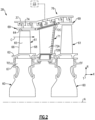
- FIG. 2 shows selected portions of the turbine section 28 including a rotor 60 carrying one or more blades or airfoils 61 that are rotatable about the engine axis A.
- like reference numerals designate like elements where appropriate and reference numerals with the addition of one-hundred or multiples thereof designate modified elements that are understood to incorporate the same features and benefits of the corresponding original elements.
- Each airfoil 61 includes a platform 62 and an airfoil section 65 extending in a radial direction R from the platform 62 to a tip 64.
- the airfoil section 65 generally extends in a chordwise or axial direction X between a leading edge 66 and a trailing edge 68.
- a root section 67 of the airfoil 61 is mounted to, or integrally formed with, the rotor 60.
- a blade outer air seal (BOAS) 69 is spaced radially outward from the tip 64 of the airfoil section 65.
- the BOAS 69 can include a plurality of seal arc segments (one exemplary BOAS shown in Figure 5 at 169) that are circumferentially arranged in an annulus around the engine axis A.
- An array of the BOAS 69 are circumferentially distributed about an array of the airfoils 61 to bound a gas path such as the core flow path C.
- a vane 71 is positioned along the engine axis A and adjacent to the airfoil 61.
- the vane 71 includes an airfoil section 72A extending between an inner platform 72B and an outer platform 72C to define a portion of the core flow path C.
- the turbine section 28 includes an array of airfoils 61, vanes 70, and BOAS 69 arranged circumferentially about the engine axis A.
- One or more cooling sources CS are configured to provide cooling air to one or more cooling cavities or plenums 74 defined by an engine static structure such as the engine case 37 or another portion of the engine static structure 36 ( Figure 1 ).
- the plenums 74 are defined between an engine case 37 and the outer platform 72C and/or BOAS 69.
- the engine case 37 provides a portion of the engine static structure 36 ( Figure 1 ) and extends along the engine axis A.
- the plenums 74 are configured to receive pressurized cooling flow from the cooling source(s) CS to cool portions of the airfoil 61, BOAS 69 and/or vane 70.
- Cooling sources CS can include bleed air from an upstream stage of the compressor section 24 ( Figure 1 ), bypass air, or a secondary cooling system aboard the aircraft, for example.
- Each of the plenums 74 can extend in a circumferential or thickness direction T between adjacent airfoils 61, BOAS 69 and/or vanes 70.
- the tips 64 of each of the airfoil sections 65 and adjacent BOAS 69 are in close radial proximity to reduce the amount of gas flow that escapes around the tips 64 through a corresponding clearance gap.
- Figures 3-9 illustrate an exemplary seal assembly 176 including a seal 169 for a gas turbine engine, which can be incorporated into the engine 20 of Figure 1 or the turbine section 28 of Figure 2 , for example.
- the seal 169 is a blade outer air seal (BOAS).
- Figure 3 is sectional view of the seal assembly 176 in an installed position.
- Figure 4 is a sectional view of an adjacent pair of seal assemblies 176 (indicated as 176A, 176B).
- the teachings herein can also be utilized for other components of the engine 20, such as one of the platforms 62, 72B, 72C, an upstream stage of the compressor section 24, or combustor panels or liners defining portions of a combustion chamber located in the combustor section 26, and exhaust nozzles.
- each seal assembly 176 includes a seal 169 and at least one support or mounting block 180.
- Each seal 169 is arranged in close proximity to an airfoil tip 164 during operation of the engine.
- An array of the seals 169 are distributed about an array of blades or airfoils 161 to bound a gas path GP.
- One pair of seals 169A, 169B is shown in Figure 4 for illustrative purposes.
- the gas path GP can be a portion of the core flow path C of Figures 1-2 , for example.
- the seal 169 includes a main body 170 that extends circumferentially between opposed (or first and second) mate faces 178.
- the main body 170 can have a generally elongated and arcuate profile, as illustrated by Figures 4-5 .
- the seal 169 includes a sealing portion 177 that extends circumferentially between the mate faces 178.
- the sealing portion 177 includes a seal face 173 that extends circumferentially between the mate faces 178, with exposed surfaces of the seal face 173 bounding the gas path GP.
- the main body 170 includes an engagement portion 179 extending radially outwardly from the sealing portion 177.
- the engagement portion 179 extends radially outwardly from the sealing portion 177 along at least one of the mate faces 178. In the illustrative example of Figure 5 , the engagement portion 179 extends circumferentially between the mate faces 178.
- the engagement portion 179 includes a backside face 175 ( Figures 4-5 ) opposite the seal face 173 relative to the radial direction R.
- the seal 169 includes an internal cavity 184 established by the main body 170.
- the internal cavity 184 extends inwardly from a pair of openings 185 along each of the respective mate faces 178.
- the engagement portion 179 defines a portion of the internal cavity 184, as illustrated by Figures 3-4 .
- the internal cavity 184 can be substantially enclosed along the main body 170 between the openings 185, as illustrated by Figure 4 .
- the internal cavity 184 can be dimensioned to span or extend circumferentially between the mate faces 178.
- the internal cavity 184 can be configured to receive cooling flow in operation, such as from the cooling source CS ( Figure 2 ), to cool adjacent portions of the seal 169.
- seal 169' includes at least one opening such as an elongated slot 191' extending radially between internal cavity 184' and a backside face 175' of the seal 169'.
- the slot 191' can be dimensioned to extend along a length of the internal cavity 184', as illustrated by Figure 10 .
- the slot 191' extends a first width W1 ( Figure 10 )
- the retention feature 187 extends a second width W2 ( Figure 6 ).
- the first width W1 is less than the second width W2.
- the engagement portion 179 extends a third width W3 ( Figure 10 ) in the thickness direction T.
- the slot 191' can be dimensioned such that the first width W1 is no more than approximately 5 or 10 percent of the third width W3 for each position, or at least a majority of positions, along the slot 191'.
- the slot 191' can be utilized to compensate for differential thermal growth and reduce thermal stresses in the component.
- each mounting block 180 secures one or more of the seals 169 to a housing such as engine case 137, or to another portion of the engine static structure 36 ( Figure 1 ).
- the mounting block 180 includes at least one interface portion 181 extending outwardly from a main body or mounting portion 182.
- the mounting block 180 includes a pair of opposed interface portions 181 that extend outwardly from the mounting portion 182.
- Each interface portion 181 is dimensioned to abut the engagement portion 179 of the respective seal 169 to limit relative movement between the mounting block 180 and the seal 169 in the radial and/or circumferential directions, for example.
- a cross-section of the mounting block 180 can have a generally trapezoidal geometry, as illustrated by Figures 4 and 6 . Ends of the interface portions 181 can be contoured to guide the interface portions 181 during insertion into the respective internal cavities 184 in an installed position.
- each of the interface portions 181 has a dovetail geometry. Surfaces of each interface portion 181 slope outwardly between a top 182A and bottom 182B of the mounting portion 182. The dovetail geometry and contouring of the interface portions 181 can reduce mechanical stress on the seal 169, including seals made of a composite material which can be strong but relative brittle.
- the dovetail geometry of the interfaces portion 181 circumferentially overlaps with the engagement portions 179 when in the installed position to secure adjacent pairs of the seal assemblies 176 to the engine case 137, as illustrated by the seal assemblies 176A, 176B of Figure 4 .
- Each interface portion 181 can include an outwardly extending retention feature 187.
- the retention feature 187 is dimensioned to abut against surfaces of the engagement portion 179 to seat the seal 169 during assembly and limit circumferential and/or radial movement, as illustrated by the retention features 187 of Figure 4 .
- the mounting block 180 can be mechanically attached or otherwise secured to the engine case 137 using one or more fasteners 190 (one shown in Figures 3-4 for illustrative purposes).
- Each mounting portion 182 defines an aperture 188 that receives a respective fastener 190 to mechanically attach the mounting portion 182 to the engine case 137 and limit relative movement of one or more seals 169.
- the fastener 190 is a bolt, and the aperture 188 threadably receives a length of the bolt.
- Other fasteners such as pins, rivets and clips, and other techniques such as welding can be utilized to secure the mounting block 180 to the engine static structure 136.
- the seal assemblies 176A, 176B are arranged in close proximity such that the respective mate faces 178A, 178B establish an intersegment gap G that extends a distance in the circumferential direction T, as illustrated in Figure 4 .
- the mounting block 180 is dimensioned to span across the intersegment gap G.
- a portion of the fastener 190 can be circumferentially aligned with one or more of the adjacent mate faces 178A, 178B and/or the intersegment gap G.
- the mounting block 180 is arranged between the engagement portions 179A, 179B to circumferentially space apart the seals 169A, 169B.
- Each mounting block 180 secures an adjacent pair of the engagement portions 179A, 179B to the engine case 137 when in the installed position.
- Each engagement portion 179A, 179B includes ramped surfaces 186A, 186B extending along the internal cavity 184A, 184B.
- the ramped surfaces 186A, 186B extend transversely from internal surfaces bounding the internal cavity 184A, 184B.
- Each interface portion 181 of the mounting block 180 is dimensioned to be inserted into or otherwise extend through a respective one of the openings 185A, 185B to abut against and mate with the ramped surfaces 186A, 186B to support the adjacent seals 169A, 169B and to limit or bound circumferential, radial and/or axial movement of the seals 169A, 169B relative to the engine case 137 and engine axis A.
- the seal 169 can include slots 183 along the respective mate faces 178, as illustrated by Figures 8-9 . Each slot 183 can be dimensioned to extend along surfaces of the platform insert 197, as illustrated by Figures 8-9 . Each slot 183 can be dimensioned to receive a seal member SM (shown in dashed lines in Figure 4 for illustrative purposes).
- the seal member SM can be a feather seal, for example, and can be dimensioned to span between the mate faces 178 of adjacent seals 169 to reduce a likelihood of ingestion of hot combustion gases from the gas path GP being communicated into and through the intersegment gap G, as illustrated by the arrangement of the mate faces 178A, 178B and seal member SM of Figure 4 .
- the slots 183 can be formed by an ultrasonic machining technique, for example.
- the slot 183 can be dimensioned to substantially align with a direction of adjacent core and/or overwrap layers CL, OL, which can reduce a likelihood of strength degradation of the adjacent layers CL, OL.
- the seal 169 is made of a first material
- the mounting block 180 is made of a second material, which can be the same or can differ from the first material.
- the first material can include a ceramic or ceramic matrix composite (CMC) material such as silicon carbide (SiC) fibers in a silicon carbide (SiC) matrix.
- CMC ceramic or ceramic matrix composite
- the seal 169 can be formed from one or more layers L ( Figure 7-8 ) of a composite layup.
- the seal 169 is made of another material, such as a high temperature metal, alloy, or composite material.
- the mounting block 180 can be made of a high temperature composite, metal, or alloy, such as a nickel-based superalloy, for example.
- the seal 169 can have a unitary construction.
- the sealing portion 177 and engagement portion 179 are separate and distinct components that are mechanically attached to one another with one or more fasteners.
- the seal 169 is formed from a plurality of plies or layers L (see also L' of Figure 11 ).
- the main body 170 of the seal 169 includes at least a core 192 and an overwrap 194.
- the main body 170 can include a platform insert 197 dimensioned to extend between portions of the core 192 and the overwrap 194 to establish at least the sealing portion 177, as illustrated by Figures 7-9 .
- the platform insert 197 can have a substantially planar geometry and can be dimensioned to extend within the sealing portion 177 between opposed portions of the overwrap 194, including portions of the overwrap 194 that establish leading and trailing edge segments 177LE, 177TE of the sealing portion 177, as illustrated by Figures 7-9 .
- the leading and trailing edge segments 177LE, 177TE extend circumferentially between the mate faces 178.
- the platform insert 197 has a third construction, which can be the same or can differ from the first and/or second fiber constructions.
- the platform insert 197 can be a monolithic component constructed from a metal material, a glass material and/or a ceramic material, which can be the same or different ceramic material as the core 192 and/or overwrap 194.
- the platform insert 197 is made of a homogenous monolithic ceramic or glass-ceramic.
- Example metal materials can include high temperature metals or alloys, including any of those disclosed herein.
- the platform insert 197 includes at least one or more interstitial or intermediate (or platform) plies or layers 193.
- the main body 170 can include one or more fillers 195.
- the intermediate layer(s) 193 and/or fillers 195 can be situated between portions of the core 192 and/or overwrap 194 to establish the sealing portion 177, as illustrated in Figures 7-9 .
- Various materials can be utilized to form the intermediate layer(s) 193 and filler(s) 195, including any of the materials disclosed herein.
- the intermediate layer(s) can serve to increase rigidity of the sealing portion 177 adjacent to regions established by the fillers 195 and can improve thermal performance along the gas path wall established by the sealing portion 177.
- the core 192 includes one or more core plies or layers CL.
- the overwrap 194 includes one or more overwrap plies or layers OL.
- the layers L of the seal 169 comprise the core and overwrap layers CL, OL and the intermediate layer(s) 193.
- the seal 169 includes six separate and distinct core plies CL, three separate and distinct overwrap plies OL, and two separate and distinct intermediate layers 193. It should be understood that fewer or more than six core plies CL, three overwrap pies OL and two intermediate layers 193 can be utilized in accordance with the teachings disclosed herein.
- the core and overwrap plies CL, OL and intermediate layers 193 are arranged in stacked relation to establish the main body 170 of the seal 169.
- the core plies CL are arranged to establish an inner, generally tubular shaped box.
- the overwrap plies OL are arranged to establish an outer, generally tubular shaped box that substantially encloses the inner box to establish a double box architecture.
- the inner box established by the core plies CL can serve to provide structural support, and the outer box established by the overwrap plies OL can serve to provide additional structural support and enclose other features such as the intermediate layer(s) 193 and filler(s) 195 to establish a cross-sectional profile of the seal 169.
- the core and/or overwrap plies CL, OL and/or intermediate layer(s) 193 can be dimensioned to extend from, and span circumferentially between, the mate faces 178.
- the continuous inner and outer box arrangement can reduce a likelihood of delamination of the plies CL, OL.
- the core plies CL are arranged to establish the internal cavity 184.
- the overwrap plies OL of the overwrap 194 are arranged to follow a perimeter P of the core 192 comprising the core plies CL to establish the sealing portion 177 and engagement portion 179.
- the overwrap 194 can be dimensioned to surround the perimeter P of the core plies CL at circumferential positions along the internal cavity 184, as illustrated by Figure 7 .
- the core plies CL follow an inner periphery or passageway OP of the overwrap 194, as illustrated by Figure 7 .
- the core plies CL establish the ramped surfaces 186 and can be arranged to space apart the overwrap plies OL of the overwrap 194 from the internal cavity 184, as illustrated by Figure 8 .
- the ramped surfaces 186 can be utilized to improve non-binding thermal growth of the mounting block 180.
- the internal cavity 184 can serve to provide an area where a cross section of the seal 169 is allowed to change to accommodate thermal distortions of the engine case 137.
- the plies CL, OL and/or intermediate layer(s) 193 can be constructed from fibers made of the same material or different materials.
- the core plies CL, overwrap plies OL and/or intermediate layer(s) 193 include silicon-based fibers in a silicon-based ceramic matrix such as silicon carbide fibers (SiC) in a silicon carbide (SiC) matrix to establish a ceramic matrix composite (CMC) component.
- Other materials can be utilized to construct the core plies CL, overwrap plies OL and/or intermediate layer(s) 193, and corresponding matrix materials, such as oxide-based chemistries.
- the core plies CL have a first fiber construction.
- the overwrap plies OL have a second fiber construction, which can be the same or can differ from the first fiber construction.
- Each intermediate layer 193 of the platform insert 197 has a third fiber construction, which can be the same or can differ from the first and/or second fiber constructions.
- the first, second and third fiber constructions can include any of the fiber constructions or patterns disclosed herein.
- Example fiber constructions include unidirectional fibers and fabrics including woven fibers.
- the first and second fiber constructions of the core and overwrap plies CL, OL comprise substantially continuous fibers
- the third fiber construction of each intermediate layer 193 comprises substantially discontinuous fibers.
- continuous means a construction in which fibers in the respective ply or layer wrap or extend more than one full rotation about an axis of the component.
- discontinuous means a construction in which fibers in the respective ply or layer do not wrap or extend more than one full rotation about an axis of the component.
- the term “substantially” with respect to “continuous” means a construction in which at least 97% of the bias and other non-axial fibers in the respective ply or layer wrap or extend more than one full rotation about an axis of the component.
- the term “substantially” with respect to “discontinuous” means a construction in which no more than 3% of the fibers or tows of fibers in the respective ply or layer wrap or extend more than one full rotation about an axis of the component.
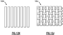
- Figures 12A-12K illustrate example fiber constructions 189 (indicated at 189A-189K).
- the core and/or overwrap plies CL, OL are constructed from braided plies including a plurality of braided yarns forming a weave, and the intermediate layer(s) 193 are constructed from a woven fabric.
- the overwrap plies OL can include a plurality of biaxially braids 189A (shown in Figure 12A ), and core plies CL can include a plurality of triaxially braids 189B (shown in Figure 12B ), or vice versa.
- the layup of the core and/or overwrap plies CL, OL include alternating layers of biaxially braided and triaxially braided plies.
- the biaxially braid 189A includes a first set of bias tows 189A-1 interlaced with a second set of bias tows 189A-2.
- the bias tows 189A-1, 189A-2 are illustrated as being arranged in a 2x2 pattern. However, other patterns such as a 1 ⁇ 1 pattern can be utilized.
- the bias tows 189A-1, 189A-2 are arranged to establish respective positive and negative bias angles ⁇ with respect to a longitudinal axis LA generally extending in a braid direction BD.
- the tows can be arranged such that the 0° angle used herein has a major component extending in the circumferential direction X ( Figures 3-4 ) of the seal 169.
- the bias angle ⁇ of each of the bias tows 189A-1, 189A-2 can be less than or equal to approximately 45 degrees, absolute. In examples, the bias angle ⁇ of each of the bias tows 189A-1, 189A-2 approaches 0 degrees, absolute, such as between approximately 30 degrees and approximately 40 degrees, absolute. For purposes of this disclosure the terms “substantially” and “approximately” mean ⁇ 3% of the stated value unless otherwise disclosed.
- the second fiber construction of each overwrap ply OL is a +/- 38° biaxial braid. The relatively shallow bias angles ⁇ of the bias tows 189A-1, 189A-2 can compensate for a lack of axial fibers in the respective ply.
- the triaxially braid 189B includes first and second sets of bias tows 189B-1, 189B-2 and a set of axial tows 189B-3 interlaced with the bias tows 189B-1, 189B-2.
- Each axial tow 189B-3 is arranged along a longitudinal axis LA generally extending in a braid direction BD.
- the bias tows 189B-1, 189B-2 are arranged to establish respective positive and negative bias angles ⁇ with respect to the longitudinal axis LA.
- the bias angle ⁇ of each of the bias tows 189B-1, 189B-2 is greater than or equal to approximately 45 degrees, absolute.
- the bias angle ⁇ of each of the bias tows 189B-1, 189B-2 approaches 90 degrees, absolute, such as between approximately 60 degrees and approximately 70 degrees, absolute.
- the 90° position is normal to the axial or braid direction BD.
- the first fiber construction of each core ply CL is a 0°, +/- 65° triaxial braid.
- the axial tows can provide thermal resistance to thermal uncurling.
- the relatively steep bias angles ⁇ of the bias tows 189B-1, 189B-2 can improve strength in the hoop direction (e.g., thickness and/or radial directions R, T).
- the biaxial braid 189A and triaxial braid 189B can include different fiber types in the braid axial and braid bias directions to tailor the strength and stiffness of the core and/or overwrap plies CL, OL. For example, higher modulus fibers may be used in conjunction with lower modulus fibers. Other fiber constructions can be utilized to form the core and/or overwrap plies CL, OL, including any of the fiber constructions disclosed herein.
- Example fabrics include a three-dimensional woven fabric 189C ( Figure 12C ), a non-crimp fabric 189D ( Figure 12D ), and/or a two-dimensional woven fabric 189E ( Figure 12E ) can be utilized to form any of the layers CL, OL and/or intermediate layers 193 disclosed herein.
- Other example fabrics that can be utilized include satin weaves.
- Example satin weaves include four-to-eight harness satin weaves such as a four-harness satin weave 189F ( Figure 12F ), a five-harness satin weave 189G ( Figure 12G ) and an eight-harness satin weave 189H ( Figure 12H ) having warp tows 189F-1/189G-1/189H-1 interlaced with weft tows 189F-2/189G-2/189H-2.
- Other example configurations include a plain weave ( Figure 12K ), and a twill weave 189I including warp tows 189I-1 interlaced with weft tows 189I-2 (disclosed as a 2x2 pattern in Figure 12I ).
- the warp tows or the weft tows can be dimensioned to substantially span between the mate faces 178.
- Other example constructions include a one-dimensional unidirectional pattern 189J ( Figure 12J ).
- the intermediate layer 193 is constructed from a section of a biaxial or triaxial braided weave in which the continuous fibers are severed and the section is flattened or otherwise formed with respect to a predefined geometry of the platform insert 197.
- Figure 13 illustrates a process of constructing or forming a component in a flow chart 296.
- the process 296 can be utilized to form a gas turbine engine component, including the seals 69, 169, or another component such as static vanes and struts, for example.
- Step 296A includes laying up or forming one or more core plies CL along at least one mandrel M.
- the core plies CL can include any of the materials and fiber constructions disclosed herein.
- a total of six core plies CL are triaxially braided about or over the mandrel M.
- the mandrel M includes a pair of mandrels M-1, M2 arranged in an opposed relationship.
- the mandrels M-1, M2 are constructed according to a predefined geometry of an internal cavity of the main body 270 (see, e.g., cavity 184 of Figures 4 and 7-8 ).
- the mandrels M-1, M-2 can be held in tooling T (shown in dashed lines for illustrative purposes).
- the tooling T can be operable to change an orientation or position of the mandrels M-1, M-2 during fabrication.
- a platform insert 297 is situated or positioned along the core plies CL of the core 292 at step 296B.
- the platform insert 297 can include at least one or more intermediate (or platform) plies or layers 293 situated or laid up along the core plies CL of the core 292.
- One or more fillers 295 can be situated or positioned along the core plies CL at step 296C.
- the platform insert 297 including the intermediate layer(s) 293 and the fillers 295 can include any of the materials and fiber constructions disclosed herein.
- the filler 295 is made of chopped fibers in a matrix.
- an overwrap 294 is formed at step 296D.
- Step 296D includes laying up or forming one or more overwrap plies OL over an overwrap mandrel OM (shown in dashed lines for illustrative purposes.
- the overwrap mandrel OM can have a generally cylindrical geometry, for example.
- the overwrap plies OL can include any of the materials and fiber constructions disclosed herein.
- a total of three overwrap plies OL are biaxially braided about or over the overwrap mandrel OM.
- the overwrap plies OL are formed such that a passageway OP is established (see also Figure 7 ).
- the overwrap 294 and platform insert 297 are positioned or situated relative to the core plies CL ( Figures 13-14 ) of the core 292 and mandrels M-1, M-2 at step 296E.
- Step 296E can include inserting the core plies CL ( Figures 13-14 ) and platform insert 297 ( Figure 15 ) at least partially into the passageway OP such that the core 292, overwrap 294 and platform insert 297 cooperate to establish a sealing portion 277 and such that at least the core 292 and overwrap 294 cooperate to establish an engagement portion 279.
- Step 296E can include moving the overwrap 294 in a direction D1 along a length of the mandrels M-1, M-2.
- the sealing and engagement portions 277, 279 can be arranged as disclosed by the sealing and engagement portions 177, 179 of the seal 169 to establish the seal assembly 176 including mounting block 180, for example.
- Steps 296A-296E occur such that an integral preform is established.
- the overwrap 294 of Figure 16 including the passageway OP can be shaped to a predefined contour of the component, which can correspond to an outer periphery of the mandrels M-1, M-2 and core 292, as illustrated in Figure 17 .
- Steps 296A, 296B and 296E can occur such that the core and overwrap plies CL, OL and/or platform insert 297 including the intermediate layer(s) 293 span between the mate faces 278, as illustrated by Figures 14-15 and 17 .
- Step 296F can include embedding the fibers of the seal 269 in a matrix material, such as carbon-based fibers in a carbon-based ceramic matrix, including silicon carbide (SiC) fibers in a silicon carbide (SiC) matrix.
- Step 296F includes removing the mandrels M-1, M-2 from the main body 270 to establish an internal cavity spanning circumferentially between openings along the mate faces 278 (see, e.g., the cavity 184 of Figures 7-8 and openings 185 of Figures 5-6 and 8 ).
- Various techniques can be utilized to establish the matrix, including chemical vapor infiltration (CVI) or a melt infiltration (MI) technique. Thereafter, the component is cured in a mold to establish an integral component.
- CVI chemical vapor infiltration
- MI melt infiltration
- Step 296G can include machining one or more surfaces of the component.
- Step 296G can include forming one or more features in the component such as an elongated opening or slot (see, e.g., slot 191' of Figures 10-11 ).
Landscapes
- Engineering & Computer Science (AREA)
- Chemical & Material Sciences (AREA)
- Ceramic Engineering (AREA)
- Mechanical Engineering (AREA)
- General Engineering & Computer Science (AREA)
- Manufacturing & Machinery (AREA)
- Materials Engineering (AREA)
- Structural Engineering (AREA)
- Organic Chemistry (AREA)
- Chemical Kinetics & Catalysis (AREA)
- Composite Materials (AREA)
- Turbine Rotor Nozzle Sealing (AREA)
Claims (15)
- Dichtungsanordnung (176) für einen Gasturbinenmotor (20), umfassend:eine Dichtung (69; 169; 269), die einen Hauptkörper (170; 270) beinhaltet, der sich in Umfangsrichtung zwischen gegenüberliegenden Passflächen (178; 278) erstreckt, wobei der Hauptkörper einen Dichtungsabschnitt (177; 277) und einen Eingriffsabschnitt (179; 279), der sich von dem Dichtungsabschnitt entlang mindestens einer der Passflächen nach außen erstreckt, beinhaltet; undwobei der Hauptkörper Folgendes beinhaltet:einen Kern (192; 292), der eine oder mehrere Kernlagen beinhaltet, die einen im Wesentlichen Endlosfasern umfassenden ersten Faseraufbau aufweisen und so angeordnet sind, dass sie einen inneren Hohlraum (184) bilden;eine Umhüllung (194; 294), die eine oder mehrere Umhüllungslagen beinhaltet, die einen im Wesentlichen Endlosfasern umfassenden zweite Faseraufbau aufweisen und so angeordnet sind, dass sie einem Umfang der einen oder mehreren Kernlagen folgen, um den Eingriffsabschnitt und den Dichtungsabschnitt zu bilden, und wobei sich der zweite Faseraufbau von dem ersten Faseraufbau unterscheidet; undeinen Plattformeinsatz (197; 297), der sich zwischen Abschnitten des Kerns und der Umhüllung erstreckt, um den Dichtungsabschnitt zu bilden, und wobei der Plattformeinsatz einen Aufbau aufweist, der sich von dem ersten und dem zweiten Faseraufbau unterscheidet, dadurch gekennzeichnet, dass der Plattformeinsatz mindestens eine Zwischenlage beinhaltet, die sich zwischen Abschnitten des Kerns und der Umhüllung befindet, um den Dichtungsabschnitt zu bilden, und die mindestens eine Zwischenlage einen dritten Faseraufbau aus im Wesentlichen Nicht-Endlosfasern aufweist.
- Dichtungsanordnung (176) nach Anspruch 1, wobei der innere Hohlraum (184) in Umfangsrichtung zwischen den Passflächen (178; 278) verläuft.
- Dichtungsanordnung (176) nach Anspruch 1 oder Anspruch 2, wobei der Plattformeinsatz (197; 297) bemessen ist, um sich innerhalb des Dichtungsabschnitts (177; 277) zwischen gegenüberliegenden Abschnitten der Umhüllung (194; 294) zu erstrecken.
- Dichtungsanordnung (176) nach einem der vorhergehenden Ansprüche, wobei der Plattformeinsatz (197; 297) ein Metallmaterial und/oder ein Keramikmaterial umfasst.
- Dichtungsanordnung (176) nach einem der vorhergehenden Ansprüche, wobei die mindestens eine Zwischenlage einen Stoff umfasst.
- Dichtungsanordnung (176) nach Anspruch 5, wobei der Stoff gewebt ist.
- Dichtungsanordnung (176) nach einem der vorhergehenden Ansprüche, wobei die eine oder die mehreren Kernlagen triaxial geflochten sind.
- Dichtungsanordnung (176) nach Anspruch 7, wobei die eine oder die mehreren Umhüllungslagen biaxial geflochten sind.
- Dichtungsanordnung (176) nach einem der vorhergehenden Ansprüche, ferner umfassend:mindestens einen Montageblock (180), der einen Schnittstellenabschnitt (181) beinhaltet, der sich von einem Montageabschnitt (182) erstreckt; undwobei der Eingriffsabschnitt (179; 279) ein Paar Öffnungen (185A, 185B) entlang jeweiliger der Passflächen (178; 278) beinhaltet und der Schnittstellenabschnitt bemessen ist, um in eine der Öffnungen eingesetzt zu werden, um eine relative Bewegung zwischen dem mindestens einen Montageblock und der Dichtung (69; 169; 269) zu begrenzen.
- Dichtungsanordnung (176) nach Anspruch 5, wobei:der Plattformeinsatz (197; 297) bemessen ist, um sich zwischen gegenüberliegenden Abschnitten der Umhüllung (194; 294) zu erstrecken, die ein Vorder- und ein Hinterkantensegment des Dichtungsabschnitts (177; 277) bilden, wobei sich das Vorder- und das Hinterkantensegment (177LE, 177TE) in Umfangsrichtung zwischen den Passflächen (178; 278) erstrecken;die eine oder die mehreren Kern- und Umhüllungslagen Siliziumkarbidfasern beinhalten, die in einer Keramikmatrix eingebettet sind;die eine oder die mehreren Kernlagen eine Vielzahl von Kernlagen umfassen, die triaxial geflochten sind und axiale Stränge (189B-3) beinhalten, die mit Schrägsträngen (189B-1, 189B-2) verflochten sind, und ein Schrägwinkel (α) von jedem der Schrägstränge zwischen ungefähr 60 Grad und ungefähr 70 Grad absolut beträgt;die eine oder die mehreren Umhüllungslagen eine Vielzahl von Umhüllungslagen umfassen, die biaxial geflochten sind und einen ersten Satz von Schrägsträngen (189A-1) beinhalten, der mit einem zweiten Satz von Schrägsträngen (189A-2) verflochten ist, und ein Schrägwinkel von jedem des ersten und des zweiten Satzes von Schrägsträngen zwischen ungefähr 30 Grad und ungefähr 40 Grad absolut beträgt; undder Stoff ein 5- oder 8-bindiges Atlas-Gewebe (189G, 189H) ist, das Kettenstränge (189G-1/189H-1) beinhaltet, die mit Schusssträngen (189G-2/189H-2) verflochten sind, und die Kettenstränge oder die Schussstränge bemessen sind, um im Wesentlichen zwischen den Passflächen zu verlaufen.
- Dichtungsanordnung (176) nach einem der vorhergehenden Ansprüche, wobei die Dichtung (69; 169; 269) eine äußere Schaufelluftdichtung (BOAS) ist.
- Gasturbinenmotor (20), umfassend:eine Dichtungsanordnung (176) nach Anspruch 1, wobei die Dichtung eine äußere Schaufelluftdichtung ist;ein Motorgehäuse (37; 237), das sich entlang einer Motorachse (A) erstreckt;ein Array von Schaufeln, die um die Motorachse drehbar sind; undein Array von Dichtungen (69; 169; 269), das um das Array von Schaufeln verteilt ist, um einen Gaspfad (GP) zu begrenzen, wobei die Passflächen dazu angeordnet sind, mit den Passflächen benachbarter Dichtungen einen Spalt (G) zwischen den Segmenten zu definieren; undein Array von in Umfangsrichtung beabstandeten Montageblöcken (180), die jeweils zwischen dem Eingriffsabschnitt (179; 279) benachbarter Paare der Dichtungen angeordnet sind, um die Dichtungen an dem Motorgehäuse zu sichern.
- Gasturbinenmotor (20) nach Anspruch 12, wobei:die Montageblöcke (180) mechanisch an dem Motorgehäuse (37; 237) befestigt sind;die Montageblöcke über den Spalt zwischen den Segmenten verlaufen, der durch die Passflächen (178; 278) des jeweiligen benachbarten Paars von Dichtungen (69; 169; 269) gebildet wird; undjeder der Montageblöcke einen eine Schwalbenschwanzgeometrie aufweisenden Schnittstellenabschnitt (181) beinhaltet, der sich durch eine Öffnung entlang einer jeweiligen der Passflächen erstreckt, um mit geneigten Oberflächen (186A, 186B) des inneren Hohlraums (184) zusammenzupassen und die Bewegung der jeweiligen Dichtung relativ zu dem Motorgehäuse zu begrenzen.
- Gasturbinenmotor (20) nach Anspruch 12 oder 13, wobei die mindestens eine Zwischenlage einen gewebten Stoff umfasst, die Kernlagen triaxial geflochten sind und die Umhüllungslagen biaxial geflochten sind.
- Gasturbinenmotor (20) nach einem der Ansprüche 12, 13 oder 14, wobei die Kern- und die Umhüllungslage Siliziumkarbidfasern beinhalten, die in einer Keramikmatrix eingebettet sind.
Applications Claiming Priority (2)
| Application Number | Priority Date | Filing Date | Title |
|---|---|---|---|
| US16/583,618 US11220924B2 (en) | 2019-09-26 | 2019-09-26 | Double box composite seal assembly with insert for gas turbine engine |
| EP20198240.2A EP3798422B1 (de) | 2019-09-26 | 2020-09-24 | Doppelkastenverbunddichtungsanordnung mit einsatz für gasturbinenmotor, gasturbinenmotor und verfahren |
Related Parent Applications (2)
| Application Number | Title | Priority Date | Filing Date |
|---|---|---|---|
| EP20198240.2A Division EP3798422B1 (de) | 2019-09-26 | 2020-09-24 | Doppelkastenverbunddichtungsanordnung mit einsatz für gasturbinenmotor, gasturbinenmotor und verfahren |
| EP20198240.2A Division-Into EP3798422B1 (de) | 2019-09-26 | 2020-09-24 | Doppelkastenverbunddichtungsanordnung mit einsatz für gasturbinenmotor, gasturbinenmotor und verfahren |
Publications (2)
| Publication Number | Publication Date |
|---|---|
| EP4219909A1 EP4219909A1 (de) | 2023-08-02 |
| EP4219909B1 true EP4219909B1 (de) | 2025-02-19 |
Family
ID=72659076
Family Applications (2)
| Application Number | Title | Priority Date | Filing Date |
|---|---|---|---|
| EP20198240.2A Active EP3798422B1 (de) | 2019-09-26 | 2020-09-24 | Doppelkastenverbunddichtungsanordnung mit einsatz für gasturbinenmotor, gasturbinenmotor und verfahren |
| EP23165729.7A Active EP4219909B1 (de) | 2019-09-26 | 2020-09-24 | Doppelkasten-verbunddichtungsanordnung mit einsatz für gasturbinenmotor |
Family Applications Before (1)
| Application Number | Title | Priority Date | Filing Date |
|---|---|---|---|
| EP20198240.2A Active EP3798422B1 (de) | 2019-09-26 | 2020-09-24 | Doppelkastenverbunddichtungsanordnung mit einsatz für gasturbinenmotor, gasturbinenmotor und verfahren |
Country Status (2)
| Country | Link |
|---|---|
| US (2) | US11220924B2 (de) |
| EP (2) | EP3798422B1 (de) |
Families Citing this family (6)
| Publication number | Priority date | Publication date | Assignee | Title |
|---|---|---|---|---|
| US11242764B2 (en) * | 2018-05-17 | 2022-02-08 | Raytheon Technologies Corporation | Seal assembly with baffle for gas turbine engine |
| US11560800B1 (en) * | 2021-11-12 | 2023-01-24 | Raytheon Technologies Corporation | Airfoil with fiber plies having interdigitated fingers in trailing end |
| US12371389B2 (en) | 2022-02-04 | 2025-07-29 | Rtx Corporation | Adaptive surface texturing for ceramic matrix composites |
| US11867067B2 (en) | 2022-06-03 | 2024-01-09 | Rtx Corporation | Engine article with ceramic insert and method therefor |
| US11873735B1 (en) * | 2022-11-10 | 2024-01-16 | General Electric Company | Composite component for a gas turbine engine |
| US12281588B1 (en) * | 2023-12-14 | 2025-04-22 | Rtx Corporation | Split case having castable pocket |
Family Cites Families (50)
| Publication number | Priority date | Publication date | Assignee | Title |
|---|---|---|---|---|
| US4087199A (en) | 1976-11-22 | 1978-05-02 | General Electric Company | Ceramic turbine shroud assembly |
| US4738902A (en) * | 1983-01-18 | 1988-04-19 | United Technologies Corporation | Gas turbine engine and composite parts |
| US4712979A (en) | 1985-11-13 | 1987-12-15 | The United States Of America As Represented By The Secretary Of The Air Force | Self-retained platform cooling plate for turbine vane |
| US4847063A (en) * | 1987-12-02 | 1989-07-11 | Fiber Materials, Inc. | Hollow composite body having an axis of symmetry |
| US5413458A (en) | 1994-03-29 | 1995-05-09 | United Technologies Corporation | Turbine vane with a platform cavity having a double feed for cooling fluid |
| JPH10103014A (ja) * | 1996-09-30 | 1998-04-21 | Toshiba Corp | ガスタービンシュラウド構造 |
| US6508620B2 (en) | 2001-05-17 | 2003-01-21 | Pratt & Whitney Canada Corp. | Inner platform impingement cooling by supply air from outside |
| US6733235B2 (en) | 2002-03-28 | 2004-05-11 | General Electric Company | Shroud segment and assembly for a turbine engine |
| US6951444B2 (en) | 2002-10-22 | 2005-10-04 | Siemens Aktiengesselschaft | Turbine and a turbine vane for a turbine |
| US6942203B2 (en) | 2003-11-04 | 2005-09-13 | General Electric Company | Spring mass damper system for turbine shrouds |
| US6997673B2 (en) | 2003-12-11 | 2006-02-14 | Honeywell International, Inc. | Gas turbine high temperature turbine blade outer air seal assembly |
| US7604456B2 (en) | 2006-04-11 | 2009-10-20 | Siemens Energy, Inc. | Vane shroud through-flow platform cover |
| US7625172B2 (en) | 2006-04-26 | 2009-12-01 | United Technologies Corporation | Vane platform cooling |
| US7771159B2 (en) * | 2006-10-16 | 2010-08-10 | General Electric Company | High temperature seals and high temperature sealing systems |
| US9039358B2 (en) | 2007-01-03 | 2015-05-26 | United Technologies Corporation | Replaceable blade outer air seal design |
| US7862291B2 (en) | 2007-02-08 | 2011-01-04 | United Technologies Corporation | Gas turbine engine component cooling scheme |
| GB0703827D0 (en) | 2007-02-28 | 2007-04-11 | Rolls Royce Plc | Rotor seal segment |
| US8016546B2 (en) | 2007-07-24 | 2011-09-13 | United Technologies Corp. | Systems and methods for providing vane platform cooling |
| US8292580B2 (en) | 2008-09-18 | 2012-10-23 | Siemens Energy, Inc. | CMC vane assembly apparatus and method |
| US8740552B2 (en) | 2010-05-28 | 2014-06-03 | General Electric Company | Low-ductility turbine shroud and mounting apparatus |
| US8636470B2 (en) | 2010-10-13 | 2014-01-28 | Honeywell International Inc. | Turbine blades and turbine rotor assemblies |
| US8714909B2 (en) | 2010-12-22 | 2014-05-06 | United Technologies Corporation | Platform with cooling circuit |
| US8834105B2 (en) | 2010-12-30 | 2014-09-16 | General Electric Company | Structural low-ductility turbine shroud apparatus |
| US8790067B2 (en) | 2011-04-27 | 2014-07-29 | United Technologies Corporation | Blade clearance control using high-CTE and low-CTE ring members |
| US9080458B2 (en) | 2011-08-23 | 2015-07-14 | United Technologies Corporation | Blade outer air seal with multi impingement plate assembly |
| US8784037B2 (en) | 2011-08-31 | 2014-07-22 | Pratt & Whitney Canada Corp. | Turbine shroud segment with integrated impingement plate |
| US8443706B2 (en) * | 2011-09-07 | 2013-05-21 | E I Du Pont De Nemours And Company | Triaxial braid fabric architectures for improved soft body armor ballistic impact performance |
| US9726043B2 (en) | 2011-12-15 | 2017-08-08 | General Electric Company | Mounting apparatus for low-ductility turbine shroud |
| GB201213039D0 (en) | 2012-07-23 | 2012-09-05 | Rolls Royce Plc | Fastener |
| EP2959113B1 (de) | 2013-02-23 | 2018-10-31 | Rolls-Royce Corporation | Profildichtung für einen gasturbinen-keramikmatrixverbundwerkstoff |
| CN105074138B (zh) | 2013-02-25 | 2017-03-29 | 通用电气公司 | 整体分段式cmc护罩悬挂器和保持器系统 |
| CA2912428C (en) | 2013-05-17 | 2018-03-13 | General Electric Company | Cmc shroud support system of a gas turbine |
| WO2015031764A1 (en) * | 2013-08-29 | 2015-03-05 | United Technologies Corporation | Blade outer air seal made of ceramic matrix composite |
| WO2015034630A1 (en) * | 2013-09-09 | 2015-03-12 | United Technologies Corporation | Airfoil with an integrally stiffened composite cover |
| JP6180007B2 (ja) | 2014-01-17 | 2017-08-16 | ゼネラル・エレクトリック・カンパニイ | Cmcシュラウド用cmcハンガースリーブ |
| US10309257B2 (en) | 2015-03-02 | 2019-06-04 | Rolls-Royce North American Technologies Inc. | Turbine assembly with load pads |
| US10370998B2 (en) | 2015-05-26 | 2019-08-06 | Rolls-Royce Corporation | Flexibly mounted ceramic matrix composite seal segments |
| US10184352B2 (en) | 2015-06-29 | 2019-01-22 | Rolls-Royce North American Technologies Inc. | Turbine shroud segment with integrated cooling air distribution system |
| GB201513236D0 (en) | 2015-07-28 | 2015-09-09 | Rolls Royce Plc | A nozzle guide vane passage |
| US10240476B2 (en) | 2016-01-19 | 2019-03-26 | Rolls-Royce North American Technologies Inc. | Full hoop blade track with interstage cooling air |
| US10221712B2 (en) | 2016-05-16 | 2019-03-05 | General Electric Company | Seal for hardware segments |
| US10415415B2 (en) | 2016-07-22 | 2019-09-17 | Rolls-Royce North American Technologies Inc. | Turbine shroud with forward case and full hoop blade track |
| US10196918B2 (en) * | 2016-06-07 | 2019-02-05 | United Technologies Corporation | Blade outer air seal made of ceramic matrix composite |
| US10480108B2 (en) * | 2017-03-01 | 2019-11-19 | Rolls-Royce Corporation | Ceramic matrix composite components reinforced for managing multi-axial stresses and methods for fabricating the same |
| US10480337B2 (en) | 2017-04-18 | 2019-11-19 | Rolls-Royce North American Technologies Inc. | Turbine shroud assembly with multi-piece seals |
| US10954809B2 (en) | 2017-06-26 | 2021-03-23 | Rolls-Royce High Temperature Composites Inc. | Ceramic matrix full hoop blade track |
| US10801349B2 (en) | 2017-08-25 | 2020-10-13 | Raytheon Technologies Corporation | Ceramic matrix composite blade outer air seal |
| US10329201B2 (en) | 2017-09-21 | 2019-06-25 | General Electric Company | Ceramic matrix composite articles formation method |
| US11021986B2 (en) * | 2018-03-20 | 2021-06-01 | Raytheon Technologies Corporation | Seal assembly for gas turbine engine |
| US11035243B2 (en) * | 2018-06-01 | 2021-06-15 | Raytheon Technologies Corporation | Seal assembly for gas turbine engines |
-
2019
- 2019-09-26 US US16/583,618 patent/US11220924B2/en active Active
-
2020
- 2020-09-24 EP EP20198240.2A patent/EP3798422B1/de active Active
- 2020-09-24 EP EP23165729.7A patent/EP4219909B1/de active Active
-
2021
- 2021-12-07 US US17/543,799 patent/US11732597B2/en active Active
Also Published As
| Publication number | Publication date |
|---|---|
| US11220924B2 (en) | 2022-01-11 |
| US20220090509A1 (en) | 2022-03-24 |
| EP4219909A1 (de) | 2023-08-02 |
| EP3798422B1 (de) | 2023-05-10 |
| US20210095571A1 (en) | 2021-04-01 |
| EP3798422A1 (de) | 2021-03-31 |
| US11732597B2 (en) | 2023-08-22 |
Similar Documents
| Publication | Publication Date | Title |
|---|---|---|
| EP4219909B1 (de) | Doppelkasten-verbunddichtungsanordnung mit einsatz für gasturbinenmotor | |
| EP3447252B1 (de) | Keramikmatrixverbundschaufelaussendichtung | |
| EP3819477B1 (de) | Federdichtungsschlitzanordnung für einen äusseren laufschaufel-luftdichtungsring aus cmc werkstoff | |
| EP3667029B1 (de) | Dichtungsanordnung eines gasturbinenmotors mit duktiler verschleissauskleidung | |
| EP3792453B1 (de) | Cmc-boas-anordnung | |
| EP3734021B1 (de) | Äussere schaufelluftdichtungsanordnung | |
| EP4219908B1 (de) | Doppelkastenverbunddichtungsanordnung mit faserdichteanordnung für gasturbinenmotor | |
| EP3798420B1 (de) | Doppelkastenverbunddichtungsanordnung für gasturbinenmotor, gasturbinenmotor und verfahren | |
| US11946391B2 (en) | Turbine engine with composite airfoil having a non-metallic leading edge protective wrap | |
| EP3739168B1 (de) | Gasturbinendeckband anordnung und verfahren | |
| EP4293201B1 (de) | Dichtungssystem für ein gasturbinentriebwerk, gasturbinentriebwerk und verfahren zur herstellung, zur reparatur oder zum austausch eines dichtungssystems | |
| EP4209660B1 (de) | Verbundbauteil mit dämpfer für gasturbinentriebwerk | |
| EP3712382B1 (de) | Äussere schaufelluftdichtungs-anordnung mit verschleissauskleidung | |
| EP3712384B1 (de) | Äussere schaufelluftdichtung mit dichtungsträger | |
| EP3736410B1 (de) | Verschachtelung von komponenten | |
| EP3819476B1 (de) | Boas-anordnung für eine gas turbine | |
| US12078083B2 (en) | Contour weaves for interwoven vanes |
Legal Events
| Date | Code | Title | Description |
|---|---|---|---|
| PUAI | Public reference made under article 153(3) epc to a published international application that has entered the european phase |
Free format text: ORIGINAL CODE: 0009012 |
|
| STAA | Information on the status of an ep patent application or granted ep patent |
Free format text: STATUS: THE APPLICATION HAS BEEN PUBLISHED |
|
| AC | Divisional application: reference to earlier application |
Ref document number: 3798422 Country of ref document: EP Kind code of ref document: P |
|
| AK | Designated contracting states |
Kind code of ref document: A1 Designated state(s): AL AT BE BG CH CY CZ DE DK EE ES FI FR GB GR HR HU IE IS IT LI LT LU LV MC MK MT NL NO PL PT RO RS SE SI SK SM TR |
|
| RAP3 | Party data changed (applicant data changed or rights of an application transferred) |
Owner name: RTX CORPORATION |
|
| STAA | Information on the status of an ep patent application or granted ep patent |
Free format text: STATUS: REQUEST FOR EXAMINATION WAS MADE |
|
| 17P | Request for examination filed |
Effective date: 20240201 |
|
| RBV | Designated contracting states (corrected) |
Designated state(s): AL AT BE BG CH CY CZ DE DK EE ES FI FR GB GR HR HU IE IS IT LI LT LU LV MC MK MT NL NO PL PT RO RS SE SI SK SM TR |
|
| GRAP | Despatch of communication of intention to grant a patent |
Free format text: ORIGINAL CODE: EPIDOSNIGR1 |
|
| RIC1 | Information provided on ipc code assigned before grant |
Ipc: C04B 35/80 20060101ALI20240802BHEP Ipc: C04B 35/83 20060101ALI20240802BHEP Ipc: C04B 35/52 20060101ALI20240802BHEP Ipc: C04B 35/573 20060101ALI20240802BHEP Ipc: F01D 11/08 20060101AFI20240802BHEP |
|
| STAA | Information on the status of an ep patent application or granted ep patent |
Free format text: STATUS: GRANT OF PATENT IS INTENDED |
|
| INTG | Intention to grant announced |
Effective date: 20240912 |
|
| GRAS | Grant fee paid |
Free format text: ORIGINAL CODE: EPIDOSNIGR3 |
|
| GRAA | (expected) grant |
Free format text: ORIGINAL CODE: 0009210 |
|
| STAA | Information on the status of an ep patent application or granted ep patent |
Free format text: STATUS: THE PATENT HAS BEEN GRANTED |
|
| AC | Divisional application: reference to earlier application |
Ref document number: 3798422 Country of ref document: EP Kind code of ref document: P |
|
| AK | Designated contracting states |
Kind code of ref document: B1 Designated state(s): AL AT BE BG CH CY CZ DE DK EE ES FI FR GB GR HR HU IE IS IT LI LT LU LV MC MK MT NL NO PL PT RO RS SE SI SK SM TR |
|
| REG | Reference to a national code |
Ref country code: GB Ref legal event code: FG4D |
|
| REG | Reference to a national code |
Ref country code: CH Ref legal event code: EP |
|
| REG | Reference to a national code |
Ref country code: DE Ref legal event code: R096 Ref document number: 602020046614 Country of ref document: DE |
|
| REG | Reference to a national code |
Ref country code: IE Ref legal event code: FG4D |
|
| REG | Reference to a national code |
Ref country code: NL Ref legal event code: MP Effective date: 20250219 |
|
| PG25 | Lapsed in a contracting state [announced via postgrant information from national office to epo] |
Ref country code: RS Free format text: LAPSE BECAUSE OF FAILURE TO SUBMIT A TRANSLATION OF THE DESCRIPTION OR TO PAY THE FEE WITHIN THE PRESCRIBED TIME-LIMIT Effective date: 20250519 |
|
| PG25 | Lapsed in a contracting state [announced via postgrant information from national office to epo] |
Ref country code: FI Free format text: LAPSE BECAUSE OF FAILURE TO SUBMIT A TRANSLATION OF THE DESCRIPTION OR TO PAY THE FEE WITHIN THE PRESCRIBED TIME-LIMIT Effective date: 20250219 |
|
| PG25 | Lapsed in a contracting state [announced via postgrant information from national office to epo] |
Ref country code: PL Free format text: LAPSE BECAUSE OF FAILURE TO SUBMIT A TRANSLATION OF THE DESCRIPTION OR TO PAY THE FEE WITHIN THE PRESCRIBED TIME-LIMIT Effective date: 20250219 |
|
| PG25 | Lapsed in a contracting state [announced via postgrant information from national office to epo] |
Ref country code: ES Free format text: LAPSE BECAUSE OF FAILURE TO SUBMIT A TRANSLATION OF THE DESCRIPTION OR TO PAY THE FEE WITHIN THE PRESCRIBED TIME-LIMIT Effective date: 20250219 |
|
| REG | Reference to a national code |
Ref country code: LT Ref legal event code: MG9D |
|
| PG25 | Lapsed in a contracting state [announced via postgrant information from national office to epo] |
Ref country code: IS Free format text: LAPSE BECAUSE OF FAILURE TO SUBMIT A TRANSLATION OF THE DESCRIPTION OR TO PAY THE FEE WITHIN THE PRESCRIBED TIME-LIMIT Effective date: 20250619 Ref country code: NO Free format text: LAPSE BECAUSE OF FAILURE TO SUBMIT A TRANSLATION OF THE DESCRIPTION OR TO PAY THE FEE WITHIN THE PRESCRIBED TIME-LIMIT Effective date: 20250519 |
|
| PG25 | Lapsed in a contracting state [announced via postgrant information from national office to epo] |
Ref country code: NL Free format text: LAPSE BECAUSE OF FAILURE TO SUBMIT A TRANSLATION OF THE DESCRIPTION OR TO PAY THE FEE WITHIN THE PRESCRIBED TIME-LIMIT Effective date: 20250219 |
|
| PG25 | Lapsed in a contracting state [announced via postgrant information from national office to epo] |
Ref country code: HR Free format text: LAPSE BECAUSE OF FAILURE TO SUBMIT A TRANSLATION OF THE DESCRIPTION OR TO PAY THE FEE WITHIN THE PRESCRIBED TIME-LIMIT Effective date: 20250219 |
|
| PG25 | Lapsed in a contracting state [announced via postgrant information from national office to epo] |
Ref country code: LV Free format text: LAPSE BECAUSE OF FAILURE TO SUBMIT A TRANSLATION OF THE DESCRIPTION OR TO PAY THE FEE WITHIN THE PRESCRIBED TIME-LIMIT Effective date: 20250219 Ref country code: PT Free format text: LAPSE BECAUSE OF FAILURE TO SUBMIT A TRANSLATION OF THE DESCRIPTION OR TO PAY THE FEE WITHIN THE PRESCRIBED TIME-LIMIT Effective date: 20250620 |
|
| PG25 | Lapsed in a contracting state [announced via postgrant information from national office to epo] |
Ref country code: GR Free format text: LAPSE BECAUSE OF FAILURE TO SUBMIT A TRANSLATION OF THE DESCRIPTION OR TO PAY THE FEE WITHIN THE PRESCRIBED TIME-LIMIT Effective date: 20250520 Ref country code: BG Free format text: LAPSE BECAUSE OF FAILURE TO SUBMIT A TRANSLATION OF THE DESCRIPTION OR TO PAY THE FEE WITHIN THE PRESCRIBED TIME-LIMIT Effective date: 20250219 |
|
| REG | Reference to a national code |
Ref country code: AT Ref legal event code: MK05 Ref document number: 1768448 Country of ref document: AT Kind code of ref document: T Effective date: 20250219 |
|
| PG25 | Lapsed in a contracting state [announced via postgrant information from national office to epo] |
Ref country code: SE Free format text: LAPSE BECAUSE OF FAILURE TO SUBMIT A TRANSLATION OF THE DESCRIPTION OR TO PAY THE FEE WITHIN THE PRESCRIBED TIME-LIMIT Effective date: 20250219 |
|
| PG25 | Lapsed in a contracting state [announced via postgrant information from national office to epo] |
Ref country code: SM Free format text: LAPSE BECAUSE OF FAILURE TO SUBMIT A TRANSLATION OF THE DESCRIPTION OR TO PAY THE FEE WITHIN THE PRESCRIBED TIME-LIMIT Effective date: 20250219 |
|
| PG25 | Lapsed in a contracting state [announced via postgrant information from national office to epo] |
Ref country code: DK Free format text: LAPSE BECAUSE OF FAILURE TO SUBMIT A TRANSLATION OF THE DESCRIPTION OR TO PAY THE FEE WITHIN THE PRESCRIBED TIME-LIMIT Effective date: 20250219 |
|
| PGFP | Annual fee paid to national office [announced via postgrant information from national office to epo] |
Ref country code: DE Payment date: 20250820 Year of fee payment: 6 |
|
| PG25 | Lapsed in a contracting state [announced via postgrant information from national office to epo] |
Ref country code: IT Free format text: LAPSE BECAUSE OF FAILURE TO SUBMIT A TRANSLATION OF THE DESCRIPTION OR TO PAY THE FEE WITHIN THE PRESCRIBED TIME-LIMIT Effective date: 20250219 |
|
| PGFP | Annual fee paid to national office [announced via postgrant information from national office to epo] |
Ref country code: GB Payment date: 20250820 Year of fee payment: 6 |
|
| PG25 | Lapsed in a contracting state [announced via postgrant information from national office to epo] |
Ref country code: AT Free format text: LAPSE BECAUSE OF FAILURE TO SUBMIT A TRANSLATION OF THE DESCRIPTION OR TO PAY THE FEE WITHIN THE PRESCRIBED TIME-LIMIT Effective date: 20250219 |
|
| PGFP | Annual fee paid to national office [announced via postgrant information from national office to epo] |
Ref country code: FR Payment date: 20250820 Year of fee payment: 6 |
|
| PG25 | Lapsed in a contracting state [announced via postgrant information from national office to epo] |
Ref country code: CZ Free format text: LAPSE BECAUSE OF FAILURE TO SUBMIT A TRANSLATION OF THE DESCRIPTION OR TO PAY THE FEE WITHIN THE PRESCRIBED TIME-LIMIT Effective date: 20250219 Ref country code: EE Free format text: LAPSE BECAUSE OF FAILURE TO SUBMIT A TRANSLATION OF THE DESCRIPTION OR TO PAY THE FEE WITHIN THE PRESCRIBED TIME-LIMIT Effective date: 20250219 |
|
| PG25 | Lapsed in a contracting state [announced via postgrant information from national office to epo] |
Ref country code: RO Free format text: LAPSE BECAUSE OF FAILURE TO SUBMIT A TRANSLATION OF THE DESCRIPTION OR TO PAY THE FEE WITHIN THE PRESCRIBED TIME-LIMIT Effective date: 20250219 |
|
| PG25 | Lapsed in a contracting state [announced via postgrant information from national office to epo] |
Ref country code: SK Free format text: LAPSE BECAUSE OF FAILURE TO SUBMIT A TRANSLATION OF THE DESCRIPTION OR TO PAY THE FEE WITHIN THE PRESCRIBED TIME-LIMIT Effective date: 20250219 |
|
| REG | Reference to a national code |
Ref country code: DE Ref legal event code: R097 Ref document number: 602020046614 Country of ref document: DE |
|
| PLBE | No opposition filed within time limit |
Free format text: ORIGINAL CODE: 0009261 |
|
| STAA | Information on the status of an ep patent application or granted ep patent |
Free format text: STATUS: NO OPPOSITION FILED WITHIN TIME LIMIT |
|
| 26N | No opposition filed |
Effective date: 20251120 |