EP4220096A1 - Durchflussmesser mit rotoranordnung - Google Patents
Durchflussmesser mit rotoranordnung Download PDFInfo
- Publication number
- EP4220096A1 EP4220096A1 EP23167094.4A EP23167094A EP4220096A1 EP 4220096 A1 EP4220096 A1 EP 4220096A1 EP 23167094 A EP23167094 A EP 23167094A EP 4220096 A1 EP4220096 A1 EP 4220096A1
- Authority
- EP
- European Patent Office
- Prior art keywords
- rotor
- flow
- metallic material
- flow meter
- shaft
- Prior art date
- Legal status (The legal status is an assumption and is not a legal conclusion. Google has not performed a legal analysis and makes no representation as to the accuracy of the status listed.)
- Pending
Links
Images

Classifications
-
- G—PHYSICS
- G01—MEASURING; TESTING
- G01F—MEASURING VOLUME, VOLUME FLOW, MASS FLOW OR LIQUID LEVEL; METERING BY VOLUME
- G01F1/00—Measuring the volume flow or mass flow of fluid or fluent solid material wherein the fluid passes through a meter in a continuous flow
- G01F1/05—Measuring the volume flow or mass flow of fluid or fluent solid material wherein the fluid passes through a meter in a continuous flow by using mechanical effects
- G01F1/10—Measuring the volume flow or mass flow of fluid or fluent solid material wherein the fluid passes through a meter in a continuous flow by using mechanical effects using rotating vanes with axial admission
- G01F1/115—Measuring the volume flow or mass flow of fluid or fluent solid material wherein the fluid passes through a meter in a continuous flow by using mechanical effects using rotating vanes with axial admission with magnetic or electromagnetic coupling to the indicating device
-
- G—PHYSICS
- G01—MEASURING; TESTING
- G01F—MEASURING VOLUME, VOLUME FLOW, MASS FLOW OR LIQUID LEVEL; METERING BY VOLUME
- G01F15/00—Details of, or accessories for, apparatus of groups G01F1/00 - G01F13/00 insofar as such details or appliances are not adapted to particular types of such apparatus
- G01F15/006—Details of, or accessories for, apparatus of groups G01F1/00 - G01F13/00 insofar as such details or appliances are not adapted to particular types of such apparatus characterised by the use of a particular material, e.g. anti-corrosive material
Definitions
- Flow meters measure the volumetric flow rate of a fluid within a pipeline.
- Some flow meters employ a rotor supported for rotation in the fluid's flow path.
- Typical rotors have paddlewheel, turbine, or Pelton-wheel designs.
- Flowing fluid through the flow path interacts with the rotor and causes the rotor to rotate.
- Measuring the rotor's resulting rotation indicates the fluid's flow rate, which can be processed to determine the volumetric flow rate of the fluid within the pipeline.
- This disclosure provides a method and apparatus for measuring a flow rate of a fluid. Specifically, this disclosure provides a rotor assembly for rotating in a flow bore in a flow meter housing, wherein the rotor assembly includes a thermally diffused metallic material.
- Fluids transported via pipeline can be laden with debris (e.g ., shale oil or gas having sand, rocks, or other debris).
- debris e.g ., shale oil or gas having sand, rocks, or other debris.
- flow meters with turbine rotors can use a tungsten carbide shaft machine pressed through the bore of a steel alloy turbine rotor.
- the tungsten carbide shaft is brittle and prone to breaking.
- the machine pressed rotor can weaken, slipping free of the shaft.
- a flow meter can include a steel alloy shaft hardened using a thermal chemical diffusion process.
- the rotor can be made integral to the shaft through additive manufacturing, eliminating a rotor that can slip free of the shaft.
- FIG. 1 shows an exploded view of flow meter 100, in accordance with one or more embodiments.
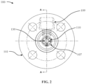
- FIG. 2 depicts a cross-section of the flow meter 100 of FIG. 1 looking down a flow bore 107, in accordance with one or more embodiments.
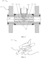
- FIG. 3 depicts a cross-section of the flow meter of FIG. 1 along the line A-A from FIG. 2 , according to one or more embodiments.
- Arrows 140 indicate the flow direction of fluid through the flow bore 107.
- the flow meter 100 includes a housing 101 that holds a rotor assembly 110 and a sensor unit 120 for measuring a condition of the rotor assembly 110, such as the rotational rate of the rotor assembly 110.
- the housing 101 includes an inlet end 103, an outlet end 105, and a flow bore 107 extending through the housing 101 between the inlet end 103 and the outlet end 105.
- the rotor assembly 110 is located at least partially in the flow bore 107 such that flow of a fluid through the flow bore 107 causes the rotor assembly 110 to rotate.
- a support assembly 130 is coupled to the housing 101 and supports the rotor assembly 110 for rotation in the flow bore 107.
- the rotor assembly 110 includes a rotor shaft 111 with a rotor 113 either coupled to or integral with the shaft 111.
- the shaft 111 is rotatably coupled to the support assembly 130, which includes support vanes 131, each having a bore 133 therethrough to receive the shaft 111.
- the bore 133 may include bearings to reduce the friction between the rotating shaft 111 and the support assembly 130.
- the housing 101 can include one or more grooves 108 to receive retainer rings 135 that fasten the support assembly 130 to the flow bore 107.
- the support assembly 130 can include any suitable device coupled to the housing 101 to the receive shaft 111 and position the rotor assembly 110 at least partially in the flow bore 107 such that flow of the fluid causes the rotor assembly 110 to rotate.
- FIG. 4 depicts the rotor assembly 110 of FIG. 1 , according to one or more embodiments.
- the rotor 113 includes one or more rotor blades 115, which are illustrated as turbine blades on a turbine rotor.
- the rotor blades 115 can include any suitable arrangement of blades, such as turbine blades, paddles on a paddlewheel, the blades on a Pelton wheel, etc.
- the rotor shaft 111 and the rotor 113 can form a single unified body constructed from the same block of material such that the rotor 113 is an extension of the shaft 111. That is, the rotor assembly 110 can include a rotor shaft 111 and rotor blades 115 integral with the rotor shaft 111.
- the rotor 113 can be fixedly coupled to the shaft 111, such as machine pressing the rotor 113 to the shaft 111.
- the rotor assembly 110 includes a thermally diffused metallic material comprising a metallic material and a diffusion substance.
- the surface of the metallic material is hardened by changing a molecular structure of the surface through thermal chemical diffusion using at least one diffusion substance.
- the diffusion substance can include at least one gas or chemical (e.g ., nitrogen, aluminum, magnesium, or silicon) that hardens or enhances the erosion resistance of the metallic material.
- the diffusion substance can include a nonmetallic material, such as a ceramic ( e.g ., aluminum oxide or silicon oxide).
- the thermally diffused metallic material can retain the ductility of the base metallic material (e.g ., steel alloy) without becoming brittle. Retaining its ductility, the hardened metallic material can resist cracking.
- the thermally diffused metallic material may include a steel alloy that retains the ductility of steel, but is hardened to enhance its resistance to erosion.
- the thermally diffused metallic material may be hardened when a hardness of the diffusion zone of the metallic material increases according to a hardness scale (e.g ., Rockwell hardness of 10, 20, 30, 40, or a higher hardness on the Rockwell C scale) relative to the hardness of the base metallic material (e.g ., steel alloy) before undergoing the thermal chemical diffusion process.
- the resulting hardness of the thermally diffused metallic material can depend on the diffusion temperature or the amount of time the metallic material is exposed to the thermal chemical diffusion process.
- the diffusion zone can be a pre-determined molecular layer of the metallic material that extends from the surface of the metallic material to a pre-determined molecular depth.
- the thermally diffused metallic material can include a steel alloy (e.g., SAE 4140 steel) or any other suitable ferrous material.
- the thermal chemical diffusion process can also enhance the corrosive resistance of the metallic material.
- the diffusion substance can also include at least one gas or chemical (e.g ., nitrogen, aluminum, magnesium, or silicon) that enhances the corrosive resistance of the metallic material.
- the thermally diffused metallic material can resist corrosion caused by salt water or seawater. Enhancing the corrosive resistance of the metallic material can allow it to resist corrosion from salt water for at least 60 days or longer of continuous exposure to salt water. Enhancing the corrosive resistance of the metallic material can include resisting a galvanic corrosion reaction in presence of seawater or other dielectric metallic materials for at least 60 days or longer.
- the rotor assembly 110 can include a thermally diffused metallic material configured to provide resistance to at least one of erosion, corrosion, and cracking.
- the shaft 111, the rotor 113, or both can include a thermally diffused metallic material.
- any suitable components included in the flow meter 100 may be molecularly altered using a thermal chemical diffusion process suitable to enhance their resistance to erosion, corrosion, or cracking.
- the housing 101, support assembly 130, or bearings in the flow meter 100 can be molecularly altered using a thermal chemical diffusion process suitable to enhance their resistance to erosion, corrosion, or cracking.
- the thermally diffused metallic material can be molecularly altered using a thermal chemical diffusion process referred to as NANOWEAR ® available from Woodworth, Inc., of Flint, Michigan.
- the rotor assembly 110 may be formed using additive manufacturing.
- An additive manufacturing process melts ultra-thin layers of a metallic material according to the desired shape of the rotor assembly 110 using a high-precision laser.
- An ultra-thin layer can include a layer that is less than or about 20 micrometers thick. This layer is formed using powder-based metallurgical techniques from known metallic materials which are suitable for multiple purposes, such as (a) corrosion resistance against most acidic and alkalinic chemical fluids, and (b) thermal chemical diffusion.
- a metallic material with suitable multiple purposes includes a steel alloy.
- Additive manufacturing can provide a reduction in cycle time ( i.e ., production lead time) due to its potential to manufacture multiple components simultaneously. Any of the components included in the flow meter 100 may be formed using additive manufacturing, subtractive manufacturing, or any other suitable manufacturing process to construct the components.
- the fluid e.g ., a hydrocarbon fluid
- the sensor unit 120 for measuring the rotational rate of the rotor 113, is located within the housing 101 through a conduit 109.
- the conduit 109 may be isolated from the flow bore 107 to prevent fluid from accessing the sensor unit 120.
- the sensor unit 120 includes a magnetic sensor 121 configured to detect the rotational rate of the rotor 113, which may include a magnetically detectable material such as a steel alloy.
- the sensor unit 120 generates a signal indicative of the rotational rate of the rotor 113, which, combined with the known dimensions of the rotor 113, blades 115, and flow bore 107, can be used to determine the flow rate of the fluid through the flow bore 107.
- a processor 150 may be in communication with the sensor unit 120 and configured to determine the flow rate of the fluid passing through the flow bore 107 using the signal generated by the sensor unit 120.
- axial and axially generally mean along or parallel to a central axis (e.g., central axis of a body or a port), while the terms “radial” and “radially” generally mean perpendicular to the central axis.
- a central axis e.g., central axis of a body or a port
- radial and radially generally mean perpendicular to the central axis.
Landscapes
- Physics & Mathematics (AREA)
- Electromagnetism (AREA)
- Fluid Mechanics (AREA)
- General Physics & Mathematics (AREA)
- Measuring Volume Flow (AREA)
- Engineering & Computer Science (AREA)
- Mechanical Engineering (AREA)
- General Engineering & Computer Science (AREA)
- Chemical & Material Sciences (AREA)
- Materials Engineering (AREA)
- Architecture (AREA)
Applications Claiming Priority (3)
| Application Number | Priority Date | Filing Date | Title |
|---|---|---|---|
| US15/277,901 US10203232B2 (en) | 2016-09-27 | 2016-09-27 | Flow meter with rotor assembly |
| PCT/US2017/053043 WO2018063941A1 (en) | 2016-09-27 | 2017-09-22 | Flow meter with rotor assembly |
| EP17857240.0A EP3519779A4 (de) | 2016-09-27 | 2017-09-22 | Durchflussmesser mit rotoranordnung |
Related Parent Applications (1)
| Application Number | Title | Priority Date | Filing Date |
|---|---|---|---|
| EP17857240.0A Division EP3519779A4 (de) | 2016-09-27 | 2017-09-22 | Durchflussmesser mit rotoranordnung |
Publications (1)
| Publication Number | Publication Date |
|---|---|
| EP4220096A1 true EP4220096A1 (de) | 2023-08-02 |
Family
ID=61685276
Family Applications (2)
| Application Number | Title | Priority Date | Filing Date |
|---|---|---|---|
| EP23167094.4A Pending EP4220096A1 (de) | 2016-09-27 | 2017-09-22 | Durchflussmesser mit rotoranordnung |
| EP17857240.0A Ceased EP3519779A4 (de) | 2016-09-27 | 2017-09-22 | Durchflussmesser mit rotoranordnung |
Family Applications After (1)
| Application Number | Title | Priority Date | Filing Date |
|---|---|---|---|
| EP17857240.0A Ceased EP3519779A4 (de) | 2016-09-27 | 2017-09-22 | Durchflussmesser mit rotoranordnung |
Country Status (5)
| Country | Link |
|---|---|
| US (1) | US10203232B2 (de) |
| EP (2) | EP4220096A1 (de) |
| JP (1) | JP6987130B2 (de) |
| CA (1) | CA3077376C (de) |
| WO (1) | WO2018063941A1 (de) |
Families Citing this family (9)
| Publication number | Priority date | Publication date | Assignee | Title |
|---|---|---|---|---|
| NL2019028B1 (en) * | 2017-05-31 | 2018-12-11 | Kinetron Bv | Turbine flow meter, assembly, and method for measuring at least one flow characteristic |
| JP6257833B1 (ja) * | 2017-11-02 | 2018-01-10 | 東フロコーポレーション株式会社 | 流量計 |
| US10852173B2 (en) * | 2018-12-18 | 2020-12-01 | Sensia Llc | Flowmeters and methods of manufacture |
| AU2020345904A1 (en) | 2019-09-11 | 2022-04-28 | Hayward Industries, Inc. | Swimming pool pressure and flow control pumping and water distribution systems and methods |
| US11874149B2 (en) | 2020-04-27 | 2024-01-16 | Rain Bird Corporation | Irrigation flow sensor systems and methods of detecting irrigation flow |
| US11204106B1 (en) * | 2021-02-25 | 2021-12-21 | Valve Technologies, LLC | Valve assembly |
| US11137780B1 (en) | 2021-02-25 | 2021-10-05 | Valve Technologies, LLC | Fluid distribution manifold |
| US11946565B2 (en) | 2021-02-25 | 2024-04-02 | Hayward Industries, Inc. | Valve assembly |
| US11579636B2 (en) | 2021-04-22 | 2023-02-14 | Hayward Industries, Inc. | Systems and methods for controlling operations of multi-manifold fluid distribution systems |
Citations (2)
| Publication number | Priority date | Publication date | Assignee | Title |
|---|---|---|---|---|
| US6079280A (en) * | 1998-04-28 | 2000-06-27 | Data Industrial Corporation | Insertion paddle wheel flow sensor for insertion into a fluid conduit |
| US20140326075A1 (en) * | 2013-05-02 | 2014-11-06 | Sur-Flo Meters & Controls Ltd. | Paddlewheel Flow Meter with Improved Servicability and Improved Reliability Under Harsh Operating Conditions |
Family Cites Families (20)
| Publication number | Priority date | Publication date | Assignee | Title |
|---|---|---|---|---|
| US4155249A (en) * | 1977-05-16 | 1979-05-22 | Scott Forrest G | Thermal-aerosol generators |
| US4282883A (en) | 1978-07-03 | 1981-08-11 | Scitec Corporation Ltd. | Spirometers |
| US4850717A (en) * | 1982-09-17 | 1989-07-25 | Clark Eugene V | Process sensor tube having erosion and corrosion resistance |
| JPH0643907B2 (ja) | 1988-12-15 | 1994-06-08 | 山武ハネウエル株式会社 | 流量計 |
| US5182952A (en) | 1991-01-17 | 1993-02-02 | Omega Engineering, Inc. | Paddlewheel flowmeter assembly |
| US5866824A (en) * | 1997-01-24 | 1999-02-02 | American Meter Company | Gas turbine meter |
| EP0905379B1 (de) | 1997-09-25 | 2003-05-14 | Levitronix LLC | Zentrifugalpumpe und Zentrifugalpumpenanordnung |
| US6250167B1 (en) | 1998-08-31 | 2001-06-26 | M & Fc Holding Company | Removable radio frequency sensor assembly for a turbine flow meter |
| US7402276B2 (en) | 2003-07-14 | 2008-07-22 | Cooper Paul V | Pump with rotating inlet |
| US6898987B1 (en) | 2004-04-22 | 2005-05-31 | Hoffer Flow Controls, Inc. | Flow meter |
| JP4173470B2 (ja) * | 2004-08-30 | 2008-10-29 | アンリツ産機システム株式会社 | 金属検出装置 |
| DE102004052482A1 (de) * | 2004-10-28 | 2006-05-11 | Thyssenkrupp Steel Ag | Verfahren zum Herstellen eines korrosionsgeschützten Stahlblechs |
| DE102005002706B4 (de) * | 2005-01-19 | 2009-03-05 | Benteler Automobiltechnik Gmbh | Beschichtungsverfahren |
| NO329714B1 (no) * | 2008-08-21 | 2010-12-06 | Agr Subsea As | Ytre rotor i eksenterskruepumpe med en indre og en ytre rotor |
| US8096193B2 (en) | 2009-06-01 | 2012-01-17 | Fmc Technologies, Inc. | Turbine flow meter having easily removable meter cartridge |
| US8181537B2 (en) | 2009-08-31 | 2012-05-22 | Delatorre Leroy C | Linearized torque flow sensor |
| SG178488A1 (en) * | 2009-09-14 | 2012-03-29 | Micro Motion Inc | Corrosion-resistant coating for a vibratory flowmeter and method for forming the coating |
| GB2517609B (en) | 2012-06-08 | 2017-05-31 | Cameron Int Corp | Artificial heart system |
| US9263926B2 (en) * | 2012-09-10 | 2016-02-16 | Remy Technologies, L.L.C. | Permanent magnet electric machine having magnets provided with a thermal enhancement bonding coating |
| US9778081B2 (en) * | 2015-11-16 | 2017-10-03 | Cameron International Corporation | Flow meter |
-
2016
- 2016-09-27 US US15/277,901 patent/US10203232B2/en active Active
-
2017
- 2017-09-22 CA CA3077376A patent/CA3077376C/en active Active
- 2017-09-22 JP JP2019516152A patent/JP6987130B2/ja active Active
- 2017-09-22 EP EP23167094.4A patent/EP4220096A1/de active Pending
- 2017-09-22 WO PCT/US2017/053043 patent/WO2018063941A1/en not_active Ceased
- 2017-09-22 EP EP17857240.0A patent/EP3519779A4/de not_active Ceased
Patent Citations (2)
| Publication number | Priority date | Publication date | Assignee | Title |
|---|---|---|---|---|
| US6079280A (en) * | 1998-04-28 | 2000-06-27 | Data Industrial Corporation | Insertion paddle wheel flow sensor for insertion into a fluid conduit |
| US20140326075A1 (en) * | 2013-05-02 | 2014-11-06 | Sur-Flo Meters & Controls Ltd. | Paddlewheel Flow Meter with Improved Servicability and Improved Reliability Under Harsh Operating Conditions |
Non-Patent Citations (3)
| Title |
|---|
| GRENNKOTE: "Thermal Diffusion Coating | Patented anti-corrosion technology", 22 June 2016 (2016-06-22), pages 1 - 3, XP093055627, Retrieved from the Internet <URL:https://web.archive.org/web/20160622041547/http://greenkote.com:80/patented-technology> [retrieved on 20230619] * |
| WOODWORTH INC: "Nanowear resist erosion and abrasion in pipelines, oil and gas industry", 15 March 2015 (2015-03-15), XP055679345, Retrieved from the Internet <URL:https://web.archive.org/web/20150315140838/http://www.woodworthheattreating.com/nanowear.html> [retrieved on 20200324] * |
| WOODWORTH INC: "Ultrawear Woodworth Inc", 10 May 2016 (2016-05-10), pages 1 - 2, XP093055622, Retrieved from the Internet <URL:https://web.archive.org/web/20160510021046/http://www.woodworthheattreating.com/ultrawear.html> [retrieved on 20230619] * |
Also Published As
| Publication number | Publication date |
|---|---|
| CA3077376A1 (en) | 2018-04-05 |
| US20180087938A1 (en) | 2018-03-29 |
| JP2019530867A (ja) | 2019-10-24 |
| JP6987130B2 (ja) | 2021-12-22 |
| EP3519779A1 (de) | 2019-08-07 |
| US10203232B2 (en) | 2019-02-12 |
| WO2018063941A1 (en) | 2018-04-05 |
| EP3519779A4 (de) | 2020-05-06 |
| CA3077376C (en) | 2023-08-29 |
Similar Documents
| Publication | Publication Date | Title |
|---|---|---|
| US10203232B2 (en) | Flow meter with rotor assembly | |
| US9778081B2 (en) | Flow meter | |
| JP2019530867A5 (de) | ||
| Thapa | Sand erosion in hydraulic machinery. | |
| US4648281A (en) | Turbine flowmeter | |
| Silverman | The rotating cylinder electrode for examining velocity-sensitive corrosion—a review | |
| Chandel et al. | Experimental study of erosion wear in a centrifugal slurry pump using coriolis wear test rig | |
| US10012072B2 (en) | Multi-phase flow meter and methods for use thereof | |
| RU2738696C2 (ru) | Компоненты насоса для нефтегазовой скважины и способ покрытия таких компонентов | |
| EP3203209A1 (de) | Bohrlochflüssigkeitseigenschaftenmessung | |
| Tian et al. | Determination of wear coefficients for erosive wear prediction through Coriolis wear testing | |
| US6079280A (en) | Insertion paddle wheel flow sensor for insertion into a fluid conduit | |
| CN105387893B (zh) | 一种涡轮流量计的叶轮结构及其涡轮流量计 | |
| CN105393093A (zh) | 流量计 | |
| Gillies et al. | Deposition velocity correlation for water slurries | |
| Prozhega et al. | Experimental study of erosion-corrosion wear of materials: A review | |
| Dumont et al. | Electrodiffusional wall shear rate analysis in scraped surface heat exchanger | |
| US20070039380A1 (en) | Device for measuring hydralic roughness of the internal surface of a pipeline | |
| CN205483089U (zh) | 一种涡轮流量计的叶轮结构及其涡轮流量计 | |
| US771826A (en) | Device for measuring the speed of flowing liquids. | |
| Liu et al. | Study on corrosion law of coiled tubing in high CO2 gas field | |
| CN114440959B (zh) | 一种基于旋流整型的油水两相测量装置和方法 | |
| Wu et al. | Visualizing Test on the Distribution Rule of Coarse Particles in a Double Blade Pump | |
| KR200299671Y1 (ko) | 터빈 타입 유량계의 회전체 구조 | |
| Mann | Particle erosion—a new concept of flow visualization and boundary layer investigations of rotating machines at high Reynolds numbers |
Legal Events
| Date | Code | Title | Description |
|---|---|---|---|
| PUAI | Public reference made under article 153(3) epc to a published international application that has entered the european phase |
Free format text: ORIGINAL CODE: 0009012 |
|
| STAA | Information on the status of an ep patent application or granted ep patent |
Free format text: STATUS: THE APPLICATION HAS BEEN PUBLISHED |
|
| AC | Divisional application: reference to earlier application |
Ref document number: 3519779 Country of ref document: EP Kind code of ref document: P |
|
| AK | Designated contracting states |
Kind code of ref document: A1 Designated state(s): AL AT BE BG CH CY CZ DE DK EE ES FI FR GB GR HR HU IE IS IT LI LT LU LV MC MK MT NL NO PL PT RO RS SE SI SK SM TR |
|
| STAA | Information on the status of an ep patent application or granted ep patent |
Free format text: STATUS: REQUEST FOR EXAMINATION WAS MADE |
|
| 17P | Request for examination filed |
Effective date: 20240202 |
|
| RBV | Designated contracting states (corrected) |
Designated state(s): AL AT BE BG CH CY CZ DE DK EE ES FI FR GB GR HR HU IE IS IT LI LT LU LV MC MK MT NL NO PL PT RO RS SE SI SK SM TR |
|
| GRAP | Despatch of communication of intention to grant a patent |
Free format text: ORIGINAL CODE: EPIDOSNIGR1 |
|
| STAA | Information on the status of an ep patent application or granted ep patent |
Free format text: STATUS: GRANT OF PATENT IS INTENDED |