EP4220139B1 - Systèmes et procédés d'évaluation d'échantillons biologiques - Google Patents
Systèmes et procédés d'évaluation d'échantillons biologiques Download PDFInfo
- Publication number
- EP4220139B1 EP4220139B1 EP23155042.7A EP23155042A EP4220139B1 EP 4220139 B1 EP4220139 B1 EP 4220139B1 EP 23155042 A EP23155042 A EP 23155042A EP 4220139 B1 EP4220139 B1 EP 4220139B1
- Authority
- EP
- European Patent Office
- Prior art keywords
- excitation
- emission
- source
- instrument according
- optical
- Prior art date
- Legal status (The legal status is an assumption and is not a legal conclusion. Google has not performed a legal analysis and makes no representation as to the accuracy of the status listed.)
- Active
Links
Images


Classifications
-
- B—PERFORMING OPERATIONS; TRANSPORTING
- B01—PHYSICAL OR CHEMICAL PROCESSES OR APPARATUS IN GENERAL
- B01L—CHEMICAL OR PHYSICAL LABORATORY APPARATUS FOR GENERAL USE
- B01L7/00—Heating or cooling apparatus; Heat insulating devices
- B01L7/52—Heating or cooling apparatus; Heat insulating devices with provision for submitting samples to a predetermined sequence of different temperatures, e.g. for treating nucleic acid samples
-
- C—CHEMISTRY; METALLURGY
- C12—BIOCHEMISTRY; BEER; SPIRITS; WINE; VINEGAR; MICROBIOLOGY; ENZYMOLOGY; MUTATION OR GENETIC ENGINEERING
- C12Q—MEASURING OR TESTING PROCESSES INVOLVING ENZYMES, NUCLEIC ACIDS OR MICROORGANISMS; COMPOSITIONS OR TEST PAPERS THEREFOR; PROCESSES OF PREPARING SUCH COMPOSITIONS; CONDITION-RESPONSIVE CONTROL IN MICROBIOLOGICAL OR ENZYMOLOGICAL PROCESSES
- C12Q1/00—Measuring or testing processes involving enzymes, nucleic acids or microorganisms; Compositions therefor; Processes of preparing such compositions
- C12Q1/68—Measuring or testing processes involving enzymes, nucleic acids or microorganisms; Compositions therefor; Processes of preparing such compositions involving nucleic acids
- C12Q1/6844—Nucleic acid amplification reactions
- C12Q1/686—Polymerase chain reaction [PCR]
-
- G—PHYSICS
- G01—MEASURING; TESTING
- G01N—INVESTIGATING OR ANALYSING MATERIALS BY DETERMINING THEIR CHEMICAL OR PHYSICAL PROPERTIES
- G01N21/00—Investigating or analysing materials by the use of optical means, i.e. using sub-millimetre waves, infrared, visible or ultraviolet light
- G01N21/01—Arrangements or apparatus for facilitating the optical investigation
- G01N21/03—Cuvette constructions
- G01N21/0332—Cuvette constructions with temperature control
-
- G—PHYSICS
- G01—MEASURING; TESTING
- G01N—INVESTIGATING OR ANALYSING MATERIALS BY DETERMINING THEIR CHEMICAL OR PHYSICAL PROPERTIES
- G01N21/00—Investigating or analysing materials by the use of optical means, i.e. using sub-millimetre waves, infrared, visible or ultraviolet light
- G01N21/62—Systems in which the material investigated is excited whereby it emits light or causes a change in wavelength of the incident light
- G01N21/63—Systems in which the material investigated is excited whereby it emits light or causes a change in wavelength of the incident light optically excited
- G01N21/64—Fluorescence; Phosphorescence
- G01N21/6402—Atomic fluorescence; Laser induced fluorescence
-
- G—PHYSICS
- G01—MEASURING; TESTING
- G01N—INVESTIGATING OR ANALYSING MATERIALS BY DETERMINING THEIR CHEMICAL OR PHYSICAL PROPERTIES
- G01N21/00—Investigating or analysing materials by the use of optical means, i.e. using sub-millimetre waves, infrared, visible or ultraviolet light
- G01N21/62—Systems in which the material investigated is excited whereby it emits light or causes a change in wavelength of the incident light
- G01N21/63—Systems in which the material investigated is excited whereby it emits light or causes a change in wavelength of the incident light optically excited
- G01N21/64—Fluorescence; Phosphorescence
- G01N21/6428—Measuring fluorescence of fluorescent products of reactions or of fluorochrome labelled reactive substances, e.g. measuring quenching effects, using measuring "optrodes"
-
- G—PHYSICS
- G01—MEASURING; TESTING
- G01N—INVESTIGATING OR ANALYSING MATERIALS BY DETERMINING THEIR CHEMICAL OR PHYSICAL PROPERTIES
- G01N21/00—Investigating or analysing materials by the use of optical means, i.e. using sub-millimetre waves, infrared, visible or ultraviolet light
- G01N21/62—Systems in which the material investigated is excited whereby it emits light or causes a change in wavelength of the incident light
- G01N21/63—Systems in which the material investigated is excited whereby it emits light or causes a change in wavelength of the incident light optically excited
- G01N21/64—Fluorescence; Phosphorescence
- G01N21/645—Specially adapted constructive features of fluorimeters
- G01N21/6452—Individual samples arranged in a regular 2D-array, e.g. multiwell plates
-
- G—PHYSICS
- G01—MEASURING; TESTING
- G01N—INVESTIGATING OR ANALYSING MATERIALS BY DETERMINING THEIR CHEMICAL OR PHYSICAL PROPERTIES
- G01N21/00—Investigating or analysing materials by the use of optical means, i.e. using sub-millimetre waves, infrared, visible or ultraviolet light
- G01N21/62—Systems in which the material investigated is excited whereby it emits light or causes a change in wavelength of the incident light
- G01N21/63—Systems in which the material investigated is excited whereby it emits light or causes a change in wavelength of the incident light optically excited
- G01N21/64—Fluorescence; Phosphorescence
- G01N21/645—Specially adapted constructive features of fluorimeters
- G01N21/6456—Spatial resolved fluorescence measurements; Imaging
- G01N21/6458—Fluorescence microscopy
-
- G—PHYSICS
- G02—OPTICS
- G02B—OPTICAL ELEMENTS, SYSTEMS OR APPARATUS
- G02B21/00—Microscopes
- G02B21/24—Base structure
- G02B21/241—Devices for focusing
- G02B21/244—Devices for focusing using image analysis techniques
-
- B—PERFORMING OPERATIONS; TRANSPORTING
- B01—PHYSICAL OR CHEMICAL PROCESSES OR APPARATUS IN GENERAL
- B01L—CHEMICAL OR PHYSICAL LABORATORY APPARATUS FOR GENERAL USE
- B01L2200/00—Solutions for specific problems relating to chemical or physical laboratory apparatus
- B01L2200/10—Integrating sample preparation and analysis in single entity, e.g. lab-on-a-chip concept
-
- B—PERFORMING OPERATIONS; TRANSPORTING
- B01—PHYSICAL OR CHEMICAL PROCESSES OR APPARATUS IN GENERAL
- B01L—CHEMICAL OR PHYSICAL LABORATORY APPARATUS FOR GENERAL USE
- B01L2300/00—Additional constructional details
- B01L2300/06—Auxiliary integrated devices, integrated components
- B01L2300/0627—Sensor or part of a sensor is integrated
- B01L2300/0654—Lenses; Optical fibres
-
- B—PERFORMING OPERATIONS; TRANSPORTING
- B01—PHYSICAL OR CHEMICAL PROCESSES OR APPARATUS IN GENERAL
- B01L—CHEMICAL OR PHYSICAL LABORATORY APPARATUS FOR GENERAL USE
- B01L2300/00—Additional constructional details
- B01L2300/08—Geometry, shape and general structure
- B01L2300/0809—Geometry, shape and general structure rectangular shaped
- B01L2300/0829—Multi-well plates; Microtitration plates
-
- B—PERFORMING OPERATIONS; TRANSPORTING
- B01—PHYSICAL OR CHEMICAL PROCESSES OR APPARATUS IN GENERAL
- B01L—CHEMICAL OR PHYSICAL LABORATORY APPARATUS FOR GENERAL USE
- B01L2300/00—Additional constructional details
- B01L2300/16—Surface properties and coatings
- B01L2300/168—Specific optical properties, e.g. reflective coatings
-
- B—PERFORMING OPERATIONS; TRANSPORTING
- B01—PHYSICAL OR CHEMICAL PROCESSES OR APPARATUS IN GENERAL
- B01L—CHEMICAL OR PHYSICAL LABORATORY APPARATUS FOR GENERAL USE
- B01L2300/00—Additional constructional details
- B01L2300/18—Means for temperature control
-
- G—PHYSICS
- G01—MEASURING; TESTING
- G01N—INVESTIGATING OR ANALYSING MATERIALS BY DETERMINING THEIR CHEMICAL OR PHYSICAL PROPERTIES
- G01N21/00—Investigating or analysing materials by the use of optical means, i.e. using sub-millimetre waves, infrared, visible or ultraviolet light
- G01N21/62—Systems in which the material investigated is excited whereby it emits light or causes a change in wavelength of the incident light
- G01N21/63—Systems in which the material investigated is excited whereby it emits light or causes a change in wavelength of the incident light optically excited
- G01N21/64—Fluorescence; Phosphorescence
- G01N21/645—Specially adapted constructive features of fluorimeters
- G01N2021/6463—Optics
Definitions
- the present invention relates generally to an instrument for biological analysis.
- US 2008/258041 A1 discloses an instrument for biological analysis comprising an excitation source, an optical sensor, an excitation optical system, an emission optical system, a plurality of emission filters which are moveable into and out of the emission optical path, a rotatable filter wheel to which the plurality of emission filters are mounted, and a position source and corresponding position sensor configured to produce a position signal indicative of a position of an emission filter of the rotatable filter wheel.
- radiation means radiant energy released by certain electromagnetic processes that may include one or more of visible light (e.g., radiant energy characterized by one or more wavelengths between 400 nanometers and 700 nanometers or between 380 nanometers and 800 nanometers) or invisible electromagnetic radiations (e.g., infrared, near infrared, ultraviolet (UV), X-ray, or gamma ray radiation).
- visible light e.g., radiant energy characterized by one or more wavelengths between 400 nanometers and 700 nanometers or between 380 nanometers and 800 nanometers
- invisible electromagnetic radiations e.g., infrared, near infrared, ultraviolet (UV), X-ray, or gamma ray radiation.
- the excitation source may comprise electromagnetic radiation within at least a portion of the infrared (near infrared, mid infrared, and/or far infrared) or ultraviolet (near ultraviolet and/or extreme ultraviolet) portions of the electromagnetic spectrum. Additionally or alternatively, the excitation source may comprise electromagnetic radiation in other wavelength bands of the electromagnetic spectrum, for example, in the X-ray and/or radio wave portions of the electromagnetic spectrum.
- the excitation source may comprise a single source of light, for example, an incandescent lamp, a gas discharge lamp (e.g., Halogen lamp, Xenon lamp, Argon lamp, Krypton lamp, etc.), a light emitting diode (LED), an organic LED (OLED), a laser, or the like.
- emission light refers to an emission comprising an electromagnetic spectrum having a peak or maximum output (e.g., power, energy, or intensity) that is within the visible band of the electromagnetic spectrum (e.g., electromagnetic radiation within a wavelength in the range of 420 nanometers to 700 nanometers).
- a peak or maximum output e.g., power, energy, or intensity
- a lens means an optical element configured to direct or focus incident electromagnetic radiation so as to converge or diverge such radiation, for example, to provide a real or virtual image, either at a finite distance or at an optical infinity.
- the lens may comprise a single optical element having an optical power provided by refraction, reflection, and/or diffraction of the incident electromagnetic radiation.
- the lens may comprise a compound system including a plurality of optical element, for example, including, but not limited to, an acromatic lens, doublet lens, triplet lens, or camera lens.
- the lens may be at least partially housed in or at least partially enclosed by a lens case or a lens mount.
- optical power means the ability of a lens or optic to converge or diverge light to provide a focus (real or virtual) when disposed within air.
- focal length means the reciprocal of the optical power.
- diffractive power or “diffractive optical power” means the power of a lens or optic, or portion thereof, attributable to diffraction of incident light into one or more diffraction orders. Except where noted otherwise, the optical power of a lens, optic, or optical element is from a reference plane associated with the lens or optic (e.g., a principal plane of an optic).
- biological sample means a sample or solution containing any type of biological chemical or component and/or any target molecule of interest to a user, manufacturer, or distributor of the various embodiments of the present invention described or implied herein, as well as any sample or solution containing related chemicals or compounds used for the purpose of conducting a biological assay, experiment, or test.
- biological chemicals, components, or target molecules may include, but are not limited to, DNA sequences (including cell-free DNA), RNA sequences, genes, oligonucleotides, molecules, proteins, biomarkers, cells (e.g., circulating tumor cells), or any other suitable target biomolecule.
- a biological sample may comprise one or more of at least one target nucleic acid sequence, at least one primer, at least one buffer, at least one nucleotide, at least one enzyme, at least one detergent, at least one blocking agent, or at least one dye, marker, and/or probe suitable for detecting a target or reference nucleic acid sequence.
- biological components may be used in conjunction with one or more PCR methods and systems in applications such as fetal diagnostics, multiplex dPCR, viral detection, and quantification standards, genotyping, sequencing assays, experiments, or protocols, sequencing validation, mutation detection, detection of genetically modified organisms, rare allele detection, and/or copy number variation.
- one or more samples or solutions containing at least one biological targets of interest may be contained in, distributed between, or divided between a plurality of a small sample volumes or reaction regions (e.g., volumes or regions of less than or equal to 10 nanoliters, less than or equal to 1 nanoliter, or less than or equal to 100 picoliters).
- a small sample volumes or reaction regions e.g., volumes or regions of less than or equal to 10 nanoliters, less than or equal to 1 nanoliter, or less than or equal to 100 picoliters.
- reaction regions disclosed herein are generally illustrated as being contained in wells located in a substrate material; however, other forms of reaction regions according to embodiments of the present invention may include reaction regions located within through-holes or indentations formed in a substrate, spots of solution distributed on the surface a substrate, samples or solutions located within test sites or volumes of a capillary or microfluidic system, or within or on a plurality of microbeads or microspheres.
- While devices, instruments, systems, and methods according to embodiments are generally directed to dPCR and qPCR, embodiments of the present invention may be applicable to any PCR processes, experiment, assays, or protocols where a large number of reaction regions are processed, observed, and/or measured.
- a dilute solution containing at least one target polynucleotide or nucleotide sequence is subdivided into a plurality of reaction regions , such that at least some of these reaction regions contain either one molecule of the target nucleotide sequence or none of the target nucleotide sequence.
- the reaction regions containing the one or more molecules of the target nucleotide sequence are greatly amplified and produce a positive, detectable detection signal, while those containing none of the target(s) nucleotide sequence are not amplified and do not produce a detection signal, or a produce a signal that is below a predetermined threshold or noise level.
- the number of target nucleotide sequences in an original solution distributed between the reaction regions may be correlated to the number of reaction regions producing a positive detection signal.
- the detected signal may be used to determine a number, or number range, of target molecules contained in the original solution.
- a detection system may be configured to distinguish between reaction regions containing one target molecule and reaction regions containing two or at least two target molecules. Additionally or alternatively, the detection system may be configured to distinguish between reaction regions containing a number of target molecules that is at or below a predetermined amount and reaction regions containing more than the predetermined amount. In certain embodiments, both qPCR and dPCR processes, assays, or protocols are conducted using a single the same devices, instruments, or systems, and methods.
- a system, apparatus, or instrument 100 for biological analysis comprises one or more of an electronic processor, computer, or controller 200, a base, mount, or sample block assembly 300 configured to receive and/or processes a biological or biochemical sample, and/or an optical system, apparatus, or instrument 400.
- system 100 may comprise a sequencing instrument, a polymerase chain reaction (PCR) instrument (e.g., a real-time PCR (qPCR) instrument and/or digital PCR (dPCR) instrument), capillary electrophoresis instrument, an instrument for providing genotyping information, or the like.
- PCR polymerase chain reaction
- qPCR real-time PCR
- dPCR digital PCR
- Electronic processor 200 is configured to control, monitor, and/or receive data from optical system 400 and/or base 300.
- Electronic processor 200 may be physically integrated into optical system 400 and/or base 300. Additionally or alternatively, electronic processor 200 may be separate from optical system 400 and base 300, for example, an external desktop computer, laptop computer, notepad computer, tablet computer, or the like. Communication between electronic processor 200 and optical system 400 and/or base 300 may be accomplished directly via a physical connection, such as a USB cable or the like, and/or indirectly via a wireless or network connection (e.g., via Wi-Fi connection, a local area network, internet connection, cloud connection, or the like).
- Electronic processor 200 may include electronic memory storage containing instructions, routines, algorithms, test and/or configuration parameter, test and/or experimental data, or the like.
- Electronic processor 200 may be configured, for example, to operate various components of optical system 400 or to obtain and/or process data provided by base 300. For example, electronic processor 200 may be used to obtain and/or process optical data provided by one or more photodetectors
- electronic processor 200 may integrated into optical system 400 and/or base 300.
- Electronic processor 200 may communicate with external computer and/or transmit data to an external computer for further processing, for example, using a hardwire connection, a local area network, an internet connection, cloud computing system, or the like.
- the external computer may be physical computer, such as a desktop computer, laptop computer, notepad computer, tablet computer, or the like, that is located in or near system 100.
- either or both the external computer and electronic processor 200 may comprise a virtual device or system, such as a cloud computing or storage system. Data may be transferred between the two via a wireless connection, a cloud storage or computing system, or the like.
- data from electronic processor 200 e.g., from optical system 400 and/or base 300
- may be transferred to an external memory storage device for example, an external hard drive, a USB memory module, a cloud storage system, or the like.
- base 300 is configured to receive a sample holder or sample carrier 305.
- Sample holder 305 may comprise a plurality or array of spatially separated reaction regions, sites, or locations 308 for containing a corresponding plurality or array of biological or biochemical samples 310.
- Reaction regions 308 may comprise any plurality of volumes or locations isolating, or configured to isolate, the plurality of biological or biochemical samples 310.
- reaction regions 308 may comprise a plurality of through-hole or well in a substrate or assembly (e.g., sample wells in a standard microtiter plate), a plurality of sample beads, microbeads, or microspheres in a channel, capillary, or chamber, a plurality of distinct locations in a flow cell, a plurality of sample spots on a substrate surface, or a plurality of wells or openings configured to receive a sample holder (e.g., the cavities in a sample block assembly configured to receive a microtiter plate).
- a substrate or assembly e.g., sample wells in a standard microtiter plate
- sample beads, microbeads, or microspheres in a channel, capillary, or chamber a plurality of distinct locations in a flow cell
- a plurality of sample spots on a substrate surface e.g., the cavities in a sample block assembly configured to receive a microtiter plate.
- Base 300 may comprise a sample block assembly configured to control the temperature of sample holder 305 and/or biological samples 310.
- Sample block assembly 300 may comprise one or more of a sample block, a Peltier device or other apparatus for controlling or cycling temperature, and/or a heat sink (e.g., for aiding in stabilizing a temperature).
- Base 300 may comprise a thermal controller or thermal cycler, for example, to provide or perform a PCR assay.
- excitation source 402 further comprises two or more excitation filters 430 moveable into and out of excitation optical path 412, for instance, used in combination with a broadband excitation source 402.
- different excitation filters 430 may be used to select different wavelength ranges or excitation channels suitable for inducing fluorescence from a respective dye or marker within biological samples 310.
- One or more of excitation filters 430 may have a wavelength bandwidth that is at least ⁇ 10 nanometers or at least ⁇ 15 nanometers.
- excitation source 402 may comprise a plurality of individual excitation sources that may be combined using one more beamsplitters or beam combiners, such that radiation from each individual excitation source is transmitted along a common optical path, for example, along excitation optical path 412 shown in FIG. 1 .
- at least some of the individual excitation sources may be arranged to provided excitation beams that propagate along different, non-overlapping optical paths, for example, to illuminate different reaction regions of the plurality of reaction regions 308.
- Each of the individual excitation sources may be addressed, activated, or selected to illuminate reaction regions 308, for example, either individually or in groups or all simultaneously.
- the individual excitation sources may be arrange in a one-dimensional or two-dimensional array, where one or more of the individual excitation sources is characterized by a maximum or central wavelength that is different than that of at least one of the other individual excitation sources in the array.
- excitation beams 405 may be produced sequentially, for example, by sequentially turning on and off different-colored individual radiation source 425 that are characterized by different wavelengths or by sequentially placing different color filters in front of a single radiation source 425.
- excitation beams 405a, 405b may be produced simultaneously, for example, by using a multi-wavelength band filter, beamsplitter, or mirror, or by coupling together different individual radiation source 425, such as two different-colored light emitting diodes (LEDs).
- excitation source 402 produces more than two excitation beams 405, wherein excitation optical system 410 directs each of the excitation beams to one or more biological samples 310.
- One or more of individual radiant sources 425a, 425b, 425c, 425d, 425e may be characterized by a central wavelength and/or wavelength range that is differ from that of the other individual radiant sources 425a, 425b, 425c, 425d, 425e.
- FIG. 3 shows the relative energy over the wavelength spectrum for three different radiation sources.
- the dashed line plot is the spectrum of a Halogen lamp (herein referred to as "Source 1”) characterized by relatively low energy levels in the blue wavelength range of the visible spectrum and increasing energy until a peak at about 670 nanometers.
- the dash-dot spectrum plot is that of a commercially available LED light source (herein referred to as “Source 2”), which has peak energy at around 450 nanometers and a lower peak from about 530 nanometers to about 580 nanometers, then steadily decreasing energy into the red wavelength range of the visible spectrum.
- Sensor lens 438 may be configured to from an image from the emissions from one or more of the plurality of biological samples 310.
- optical sensor 408 comprises two or more array sensors 408, for example, where two or more images are formed from the emissions from one or more of the plurality of biological samples 310.
- emissions from one or more of the plurality of biological samples 310 may be split to provide two signals of the one or more of the plurality of biological samples 310.
- the optical sensor comprises at least two array sensors.
- Beamsplitter 420 is disposed along both excitation and emission optical paths 412, 417 and is configured to receive both first and second excitation beams 405a, 405b during operation. In the illustrated embodiment shown in FIG. 1 , beamsplitter 420 is configured to transmit the excitation beams 405 and to reflect emissions from the biological samples 310. Alternatively, beamsplitter 420 may be configured to reflect the excitation beams and to transmit emissions from the biological samples 310.
- beamsplitter 420 comprises a broadband beamsplitter having the same, or approximately the same, reflectance for all or most of the excitation beams 405 provided by excitation source 402 and directed to the reaction regions 308 (e.g., excitation beams 405a, 405b in the illustrated embodiment).
- beamsplitter 420 may be a broadband beamsplitter characterized by a reflectance that is constant, or about constant, over a wavelength band of at least 100 nanometers, over a wavelength band of at least 200 nanometers, or over the visible wavelength band of the electromagnetic spectrum, over the visible and near IR wavelength bands of the electromagnetic spectrum, or over a wavelength band from 450 nanometers to 680 nanometers.
- beamsplitter 420 is a neutral density filter, for example, a filter having a reflectance of, or about, 20%, 50%, or 80% over visible wavelength band of the electromagnetic spectrum.
- beamsplitter 420 is a dichroic beamsplitter that is transmissive or reflective over one or more selected wavelength ranges, for example, a multi-wavelength band beamsplitter that is transmissive and/or reflective over more than one band of wavelengths centers at or near a peak wavelength of excitation beams 405.
- beamsplitter 420 is a single beamsplitter configure to receive some or all of the plurality of excitation beams 405 (e.g., excitation beams 405a, 405b), either alone or in combination with a single beam dump 422.
- Each excitation beam may be referred to as an excitation channel, which may be used alone or in combination to excite different fluorescent dyes or probe molecule in one or more of the biological samples 310.
- many prior art systems and instruments provide a plurality of excitation beams by using a separate beamsplitter and/or beam dump for each excitation channel and/or each emission channel of the system or instrument.
- chromatically selective dichroic filters are typically used in at least some of the excitation channels to increase the amount of radiation received at the samples.
- Disadvantages of systems and instruments using different beamsplitters and/or beam dumps for each channel include an increase in size, cost, complexity, and response time (e.g., dues to increased mass that must be moved or rotated when changing between excitation and/or emission channels).
- inventions of the present invention may be used to provide systems and instruments that have reduced size, cost, complexity, and response time as compared to prior art systems and instruments.
- system 100 comprises an instrument housing 105 and sample holder drawer 110 comprising base 300 and configured during use to receive, hold, or contain sample holder 305 and to position sample holder 305 to provide optical coupling thereof with optical system 400.
- housing 105 With drawer 110 closed ( FIG. 6 ), housing 105 may be configured to contain or enclose sample processing system 300 and optical system 400. In certain embodiments, housing 105 may contain or enclose all or portions of electronic processor 200.
- optical system 400 may further comprise a lens 440 and/or a lens array 442, which may comprise a plurality of lenses corresponding to each of the reaction regions 308 of sample holder 305.
- Lens 440 may comprises a field lens, which may be configured to provide a telecentric optical system for a least one of sample holder 305, reaction regions 308, lens array 442, or optical sensor 408. As shown in illustrated embodiment in FIGS. 7 and 9 , lens 440 may comprise a Fresnel lens.
- base 300 comprises a sample block assembly 300 comprising a sample block 302, temperature controller 303, such as a Peltier device 303, and a heat sink 304.
- Sample block assembly 300 may be configured to provide a thermal controller or thermal cycling (e.g., provide a PCR assay or temperature profile), maintain a temperature of sample holder 305 or biological sample(s) 310, and/or otherwise maintain, control, adjust, or cycle heat flow or temperature of sample holder 305 or biological sample(s) 310.
- optical system 400 includes an imaging unit 445 comprising an optical sensor circuit board 448, sensor lens 438 (which may be a compound lens, as illustrated in FIG. 10 ), an inner lens mount 449, an outer lens mount 450, a threaded housing 452, and a focusing gear 455.
- Optical sensor circuit board 448, threaded housing 452, and sensor lens 438 together may form a cavity 458 that encloses or contains optical sensor 408 and may be configured to block any external light from impinging optical sensor 408 that does not enter through sensor lens 438.
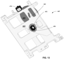
- Outer lens mount 450 comprises an outer surface containing gear teeth 460 that may be moveably or slideably engaged with the teeth of focusing gear 455 via a resilient element (not shown), such as a spring. In certain embodiments, focusing gear 455 moves or slide along a slot 462 of a plate 465, as illustrated in FIG. 14 .
- Inner lens mount 449 comprises a threaded portion 468 that engages or mates with a threaded portion of threaded housing 452.
- Inner lens mount 449 may be fixedly mounted to outer lens mount 450, while threaded housing 452 is fixedly mounted relative to optical sensor circuit board 448. Inner lens mount 449 is moveably or rotatably mounted to threaded housing 452. Thus, focusing gear 455 and outer lens mount 450 may be engaged such that a rotation of focusing gear 455 also rotates outer lens mount 450. This, in turn, causes inner lens mount 449 and sensor lens 438 to move along an optical axis of sensor lens 438 via the threads in inner lens mount 449 and threaded housing 452. In this manner, the focus of sensor lens 438 may be adjusted without directly engaging sensor lens 438 or its associated mounts 449, 450, which are buried within a very compact optical system 400. Engagement with focusing gear 455 may be either by hand or automated, for example using a motor (not shown), such as a stepper motor or DC motor.
- imaging unit 445 further comprises a locking device or mechanism 470.
- Locking device 470 comprises an edge or tooth 472 that may be slideably engaged between two teeth of focusing gear 455 (see FIGS. 15-17 ). As illustrated in FIGS. 15 and 16 , locking device 470 may have a first position ( FIG. 15 ) in which focusing gear 455 is free to rotate and adjust the focus of sensor lens 438 and a second position ( FIG. 14 ) is which focusing gear 455 is locked in position and impeded or prevented from rotating.
- locking mechanism 470 further comprises a resilient element such as a spring (not shown), wherein rotation of focusing gear 455 may be accomplished by overcoming a threshold force produced by the resilient element.
- optical system 400 may also include an optics housing 477.
- optical system 400 includes a radiation shield 475 comprising a sensor aperture 478 disposed along emission optical path 417 and at least one blocking structure 480 disposed to cooperate with sensor aperture 478 such that the only radiation from excitation beams 405, and reflected off an illuminated surface or area 482, to pass through sensor aperture 478 is radiation that has also reflected off at least one other surface of, or within, the optics housing 477.
- radiation shield 475 is configured such that radiation from excitation beams 405 reflected illuminated area 482 are blocked from directly passing through aperture 478 and, therefore, from passing into sensor lens 438 and onto optical detector 408.
- illuminated area 482 comprises the area defined by all the apertures 483 of heated cover 102 corresponding to the plurality of reaction regions 308.
- blocking structure 480 comprises a shelf 480.
- Dashed lines or rays 484a and 484b may be used to illustrate the effectiveness of blocking structure 480 in preventing light directly reflected from illuminated area 482 from passing through sensor aperture 478 and onto senor lens 438 and/or optical sensor 408.
- Ray 484a originates from an edge of illuminated area 482 an just passes shelf 480, but does not pass through sensor aperture 478.
- Ray 484b is another ray originating from the same edge of illuminated area 482 that is blocked by shelf 480. As can be seen, this ray would have entered through sensor aperture 478 were it not for the presences of shelf 480.
- optical system 400 may further comprise an energy or power detection unit comprising a power or energy sensors 490 optically coupled to one end of a light pipe 492.
- An opposite end 493 of light pipe 492 is configured to be illuminated by excitation beams 405.
- Light pipe end 493 may be illuminated either directly by radiation contained in excitation beams 405 or indirectly, for example, by radiation scattered by a diffuse surface.
- sensor 490 is located outside of the excitation optical path 412 from excitation source 402. Additionally or alternatively, sensor 490 is located outside optics housing 477 and/or is located at a remote location outside instrument housing 105. In the illustrated embodiment shown in FIG.
- light pipe end 493 is disposed near or adjacent mirror 432 and may be oriented so that the face of the light pipe is perpendicular, or nearly perpendicular, to the surface of mirror 432 that reflects excitation beams 405.
- the inventors have discovered that the low amount of energy or power intercepted by light pipe 492 when oriented in this way is sufficient for the purpose of monitoring the energy or power of excitation beams 405.
- a more compact optical system 400 may be provided.
- light pipe 492 comprises a single fiber or a fiber bundle. Additionally or alternatively, light 492 may comprise a rod made of a transparent or transmissive material such as glass, Plexiglas, polymer based material such as acrylic, or the like.
- instrument 100 comprises a position source 500 configured to emit radiation 502 and a corresponding position sensor 505 configured to receive radiation 502 from position source 500.
- Position source 500 and position sensor 505 may be configured to produce a position signal indicative of a position of an optical element 435 disposed along an optical paths.
- Instrument 100 comprises radiation shields 510 configured to block at least some radiation 502 from position source 505.
Landscapes
- Health & Medical Sciences (AREA)
- Chemical & Material Sciences (AREA)
- Physics & Mathematics (AREA)
- Life Sciences & Earth Sciences (AREA)
- Immunology (AREA)
- Analytical Chemistry (AREA)
- Biochemistry (AREA)
- General Health & Medical Sciences (AREA)
- General Physics & Mathematics (AREA)
- Pathology (AREA)
- Nuclear Medicine, Radiotherapy & Molecular Imaging (AREA)
- Chemical Kinetics & Catalysis (AREA)
- Organic Chemistry (AREA)
- Engineering & Computer Science (AREA)
- Optics & Photonics (AREA)
- Proteomics, Peptides & Aminoacids (AREA)
- Wood Science & Technology (AREA)
- Zoology (AREA)
- Molecular Biology (AREA)
- Genetics & Genomics (AREA)
- Biotechnology (AREA)
- Microbiology (AREA)
- Biophysics (AREA)
- Bioinformatics & Cheminformatics (AREA)
- General Engineering & Computer Science (AREA)
- Computer Vision & Pattern Recognition (AREA)
- Clinical Laboratory Science (AREA)
- Investigating, Analyzing Materials By Fluorescence Or Luminescence (AREA)
- Apparatus Associated With Microorganisms And Enzymes (AREA)
- Measuring Or Testing Involving Enzymes Or Micro-Organisms (AREA)
- Investigating Or Analysing Materials By The Use Of Chemical Reactions (AREA)
- Investigating Or Analysing Materials By Optical Means (AREA)
- Measuring Pulse, Heart Rate, Blood Pressure Or Blood Flow (AREA)
- Measurement Of The Respiration, Hearing Ability, Form, And Blood Characteristics Of Living Organisms (AREA)
Claims (13)
- Instrument (100) destiné à l'analyse biologique, comprenant :une source d'excitation (402) ;un capteur optique (408) configuré pour recevoir les émissions des échantillons biologiques en réponse à la source d'excitation ;un système optique d'excitation (410) disposé le long d'un chemin optique d'excitation ;un système optique d'émission (415) disposé le long d'un chemin optique d'émission ;une série de filtres d'émission (435) mobiles à l'intérieur et hors du chemin optique d'émission ;une roue filtre rotative (436) sur laquelle la totalité des filtres d'émission est montée, et configurée pour déplacer chacun des filtres à l'intérieur et hors du chemin du faisceau d'émission par rotation de la roue filtre rotative ;une source de position (500) configurée pour émettre un rayonnement (502) et un capteur de position correspondant (505) configuré pour recevoir le rayonnement de la source de position ;la source de position et le capteur de position ensemble disposés à une position radiale par rapport à la roue filtre au delà de la roue filtre rotative et configurés pour produire un signal de position indiquant une position d'un filtre d'émission de la roue filtre rotative ;un boîtier comportant une partie périphérique de la roue filtre, partie sur laquelle les filtres d'émission sont montés, la source de position et le capteur de position étant fournis sur le boîtier,;et les boucliers de rayonnement (510) s'étendant du boîtier de la roue filtre rotative à la roue filtre rotative à des positions espacées entre la source de position et le chemin du faisceau d'émission afin d'empêcher au moins une partie du rayonnement provenant de la source de position d'atteindre le chemin du faisceau d'émission.
- Instrument selon la revendication 1, comprenant en outre un séparateur de faisceau (420) disposé le long du chemin optique d'excitation et le long du chemin optique d'émission.
- Instrument selon la revendication 1 ou 2, comprenant en outre une base (300) configurée pour recevoir un porte-échantillon comprenant une pluralité de régions de réaction spatialement séparées pour le traitement d'un ou plusieurs échantillons biologiques.
- Instrument selon la revendication 3,dans lequel le système optique d'excitation est disposé le long d'un chemin optique d'excitation entre la source d'excitation et la base,dans lequel le système optique d'émission est disposé le long d'un chemin optique d'émission entre la base et le capteur optique, etdans lequel le système optique d'émission est configuré pour orienter les émissions provenant des échantillons biologiques vers le capteur optique.
- Instrument selon l'une quelconque des revendications 1 à 4,
dans lequel la source d'excitation est configurée pour produire un premier faisceau d'excitation caractérisé par une première longueur d'onde et un deuxième faisceau d'excitation caractérisé par une deuxième longueur d'onde, qui est différente de la première longueur d'onde. - Instrument selon l'une quelconque des revendications précédentes dépendant directement ou indirectement des revendications 2 et 3, comprenant en outre un couvercle à température contrôlée (102) disposé le long du chemin optique d'excitation entre la base et le séparateur de faisceau.
- Instrument selon l'une quelconque des revendications précédentes dépendant directement ou indirectement des revendications 2 et 3, comprenant en outre un miroir (432) disposé le long du chemin optique d'excitation entre la base et le séparateur de faisceau.
- Instrument selon l'une quelconque des revendications précédentes dépendant directement ou indirectement de la revendication 3, dans lequel le système optique d'excitation comprend une lentille d'échantillon configurée pour orienter les faisceaux d'excitation vers la base.
- Instrument selon l'une quelconque des revendications précédentes dépendant directement ou indirectement de la revendication 3, dans lequel la lentille d'échantillon comprend une lentille de champ (440) configurée pour s'étendre sur la pluralité de régions de réaction spatialement séparées.
- Instrument selon l'une quelconque des revendications précédentes dépendant directement ou indirectement de la revendication 3, comprenant en outre une pluralité de lentilles, chacune de la pluralité de lentilles disposée sur l'une respective de la pluralité des régions de réaction spatialement séparées.
- Instrument selon l'une quelconque des revendications précédentes, dans lequel la source d'excitation comprend une pluralité de filtres d'excitation (430) mobiles à l'intérieur et hors du chemin optique d'excitation, les filtres d'excitation étant éventuellement montés sur une roue filtre rotative (431) configurée pour déplacer chacun des filtres à l'intérieur et hors du chemin des faisceaux d'excitation.
- Instrument selon l'une quelconque des revendications précédentes, dans lequel la source d'excitation comprend une pluralité de sources d'excitation individuelles (425a, 425b, 425c, 425d, 425e), la multiplication de sources d'excitation individuelles constituant éventuellement une matrice bidimensionnelle de sources d'excitation individuelles.
- Instrument selon l'une quelconque des revendications précédentes, dans lequel le capteur optique comprend un capteur matriciel.
Priority Applications (1)
| Application Number | Priority Date | Filing Date | Title |
|---|---|---|---|
| EP25163500.9A EP4545946A3 (fr) | 2015-02-06 | 2016-02-05 | Systèmes et procédés d'évaluation d'échantillons biologiques |
Applications Claiming Priority (4)
| Application Number | Priority Date | Filing Date | Title |
|---|---|---|---|
| US201562112910P | 2015-02-06 | 2015-02-06 | |
| PCT/US2016/016886 WO2016127128A1 (fr) | 2015-02-06 | 2016-02-05 | Systèmes et procédés d'évaluation d'échantillons biologiques |
| EP16705683.7A EP3254085B1 (fr) | 2015-02-06 | 2016-02-05 | Instrument d'analyse biologique |
| EP20171301.3A EP3719481B1 (fr) | 2015-02-06 | 2016-02-05 | Un instrument optique pour l'analyse biologique |
Related Parent Applications (3)
| Application Number | Title | Priority Date | Filing Date |
|---|---|---|---|
| EP20171301.3A Division EP3719481B1 (fr) | 2015-02-06 | 2016-02-05 | Un instrument optique pour l'analyse biologique |
| EP20171301.3A Division-Into EP3719481B1 (fr) | 2015-02-06 | 2016-02-05 | Un instrument optique pour l'analyse biologique |
| EP16705683.7A Division EP3254085B1 (fr) | 2015-02-06 | 2016-02-05 | Instrument d'analyse biologique |
Related Child Applications (2)
| Application Number | Title | Priority Date | Filing Date |
|---|---|---|---|
| EP25163500.9A Division EP4545946A3 (fr) | 2015-02-06 | 2016-02-05 | Systèmes et procédés d'évaluation d'échantillons biologiques |
| EP25163500.9A Division-Into EP4545946A3 (fr) | 2015-02-06 | 2016-02-05 | Systèmes et procédés d'évaluation d'échantillons biologiques |
Publications (3)
| Publication Number | Publication Date |
|---|---|
| EP4220139A2 EP4220139A2 (fr) | 2023-08-02 |
| EP4220139A3 EP4220139A3 (fr) | 2023-08-09 |
| EP4220139B1 true EP4220139B1 (fr) | 2025-05-28 |
Family
ID=55404853
Family Applications (4)
| Application Number | Title | Priority Date | Filing Date |
|---|---|---|---|
| EP23155042.7A Active EP4220139B1 (fr) | 2015-02-06 | 2016-02-05 | Systèmes et procédés d'évaluation d'échantillons biologiques |
| EP16705683.7A Active EP3254085B1 (fr) | 2015-02-06 | 2016-02-05 | Instrument d'analyse biologique |
| EP25163500.9A Pending EP4545946A3 (fr) | 2015-02-06 | 2016-02-05 | Systèmes et procédés d'évaluation d'échantillons biologiques |
| EP20171301.3A Revoked EP3719481B1 (fr) | 2015-02-06 | 2016-02-05 | Un instrument optique pour l'analyse biologique |
Family Applications After (3)
| Application Number | Title | Priority Date | Filing Date |
|---|---|---|---|
| EP16705683.7A Active EP3254085B1 (fr) | 2015-02-06 | 2016-02-05 | Instrument d'analyse biologique |
| EP25163500.9A Pending EP4545946A3 (fr) | 2015-02-06 | 2016-02-05 | Systèmes et procédés d'évaluation d'échantillons biologiques |
| EP20171301.3A Revoked EP3719481B1 (fr) | 2015-02-06 | 2016-02-05 | Un instrument optique pour l'analyse biologique |
Country Status (10)
| Country | Link |
|---|---|
| US (4) | US20160230210A1 (fr) |
| EP (4) | EP4220139B1 (fr) |
| JP (3) | JP6985144B2 (fr) |
| KR (3) | KR102836389B1 (fr) |
| CN (2) | CN113049553B (fr) |
| BR (1) | BR112017016937B1 (fr) |
| ES (1) | ES2943159T3 (fr) |
| RU (1) | RU2708542C2 (fr) |
| SG (3) | SG10202103903UA (fr) |
| WO (1) | WO2016127128A1 (fr) |
Families Citing this family (42)
| Publication number | Priority date | Publication date | Assignee | Title |
|---|---|---|---|---|
| WO2014113785A1 (fr) | 2013-01-18 | 2014-07-24 | Biomeme Incorporated | Dispositif analytique |
| EP4220139B1 (fr) | 2015-02-06 | 2025-05-28 | Life Technologies Corporation | Systèmes et procédés d'évaluation d'échantillons biologiques |
| US10324041B2 (en) | 2016-12-21 | 2019-06-18 | Abbott Japan Co., Ltd. | Optical imaging system using lateral illumination for digital assays |
| CN206348514U (zh) * | 2016-12-23 | 2017-07-21 | 卡尔蔡司医疗技术股份公司 | 手术显微镜及使其在多种工作模式之间切换的装置 |
| US11047854B2 (en) | 2017-02-06 | 2021-06-29 | Abbott Japan Llc | Methods for reducing noise in signal-generating digital assays |
| CN111356768A (zh) | 2017-09-15 | 2020-06-30 | 生米公司 | 用于自动化样品处理的方法和系统 |
| CN112326652B (zh) * | 2017-09-20 | 2021-09-03 | 深圳市真迈生物科技有限公司 | 成像方法、控制序列测定反应的方法、装置及系统 |
| EP3724352A4 (fr) * | 2017-12-15 | 2021-09-01 | Biomeme, Inc. | Dispositifs et procédés portables pour analyser des échantillons |
| NL2020636B1 (en) | 2017-12-28 | 2019-07-08 | Illumina Inc | Light energy fluorescence excitation |
| KR102133633B1 (ko) * | 2018-04-17 | 2020-07-13 | (주)로고스바이오시스템스 | 핵산증폭반응산물을 실시간으로 검출하는 장치 |
| KR102113217B1 (ko) * | 2018-07-23 | 2020-05-21 | 광주과학기술원 | 레이저 유도 엑스선을 이용한 표적 단백질 추적 장치 |
| CN109324024A (zh) * | 2018-09-17 | 2019-02-12 | 中国人民解放军陆军军医大学第三附属医院(野战外科研究所) | 小型集成化免疫荧光分析装置 |
| US10883925B2 (en) * | 2018-09-24 | 2021-01-05 | Hf Scientific, Inc. | Spectrophotometer for use in explosive atmospheres |
| USD921222S1 (en) | 2019-01-04 | 2021-06-01 | Meso Scale Technologies, Llc. | Instrument |
| USD1016325S1 (en) | 2019-01-04 | 2024-02-27 | Meso Scale Technologies, Llc. | Instrument |
| US12298244B2 (en) | 2019-02-04 | 2025-05-13 | Life Technologies Holdings Pte Ltd | Method of analyzing samples, analyzing device and computer program |
| JP7483745B2 (ja) | 2019-03-21 | 2024-05-15 | バイオミーム インコーポレイテッド | 多機能性分析デバイス |
| CN110057808A (zh) | 2019-05-27 | 2019-07-26 | 中国人民解放军军事科学院军事医学研究院 | 样本旋转架及拉曼光谱检测仪 |
| KR102220353B1 (ko) * | 2019-06-10 | 2021-02-25 | 한국전자기술연구원 | 이미지센서를 이용한 시간제어측정 형광 리더기 시스템 |
| KR102400907B1 (ko) * | 2019-06-30 | 2022-05-24 | 주식회사 진시스템 | 휴대용 멀티플렉스 pcr 장치 |
| CN110672550B (zh) * | 2019-09-10 | 2021-11-19 | 中国科学院上海技术物理研究所 | 一种微区重要生物资源像谱分析仪 |
| CN112904013B (zh) * | 2019-12-04 | 2023-06-20 | 中国科学院大连化学物理研究所 | 一种用于生物样本的高能量紫外交联仪 |
| WO2021246745A1 (fr) * | 2020-06-03 | 2021-12-09 | Seegene, Inc. | Dispositif de détection de signal optique pour détecter de multiples signaux optiques pour de multiples analytes cibles à partir d'un échantillon |
| CA3186952A1 (fr) | 2020-07-23 | 2022-01-27 | Jacob Freudenthal | Systemes et methodes d'analyse biologique |
| WO2022020731A2 (fr) | 2020-07-23 | 2022-01-27 | Life Technologies Corporation | Compositions, systèmes et méthodes d'analyse biologique impliquant des conjugués de colorants à transfert d'énergie et analytes comprenant ceux-ci |
| CN112824521A (zh) * | 2020-07-24 | 2021-05-21 | 北京金诺美生物技术有限公司 | 一种荧光激发系统、光学系统及实时荧光定量pcr仪 |
| WO2022035853A1 (fr) * | 2020-08-12 | 2022-02-17 | University Of Washington | Systèmes et procédés d'imagerie pour tests d'amplification d'acide nucléique en temps réel (naats) |
| LU102014B1 (en) * | 2020-08-25 | 2022-02-25 | Toby Overmaat | Micro-Thermocycler |
| KR102559634B1 (ko) * | 2020-08-26 | 2023-07-26 | 한국전자통신연구원 | 다파장 광원에 기반한 pcr 진단을 위한 장치 및 방법 |
| US12054770B2 (en) | 2020-08-26 | 2024-08-06 | Electronics And Telecommunications Research Institute | Apparatus and method for PCR diagnosis based on multi-wavelength light source |
| JP2023545631A (ja) * | 2020-09-18 | 2023-10-31 | バイオミーム,インコーポレイテッド | 試料を分析するための運搬可能デバイスおよび方法 |
| KR102380565B1 (ko) * | 2020-09-18 | 2022-03-30 | (주)얼라인드제네틱스 | 시료의 형광을 검출하기 위한 시료 검사 장치 |
| TWI859369B (zh) * | 2020-11-27 | 2024-10-21 | 緯創資通股份有限公司 | 檢測裝置與檢測方法 |
| CN113092424B (zh) * | 2021-03-18 | 2023-02-10 | 上海医本医疗器械有限公司 | 一种高通量生物芯片分析仪 |
| CN113122614B (zh) * | 2021-04-15 | 2021-11-16 | 珠海市尚维高科生物技术有限公司 | 一种荧光定量pcr处理方法和系统 |
| WO2023055340A1 (fr) * | 2021-09-28 | 2023-04-06 | Hewlett-Packard Development Company, L.P. | Appareils à agents de capture immobilisés dans une région de réaction d'une chambre |
| CN113777768A (zh) * | 2021-10-13 | 2021-12-10 | 大连理工大学 | 基于3d打印制造的显微成像及光学传感物联网系统 |
| EP4419893A4 (fr) * | 2021-10-20 | 2025-08-06 | Bio Rad Laboratories Inc | Système de détection de fluorescence |
| KR102821812B1 (ko) * | 2021-11-08 | 2025-06-17 | 한국전자통신연구원 | 다파장 광원 및 직교하는 코드 신호들에 기반한 pcr 진단을 위한 장치 및 방법 |
| US12320747B2 (en) | 2021-11-08 | 2025-06-03 | Electronics And Telecommunications Research Institute | Apparatus and method for PCR diagnosis based on multi-wavelength light source and orthogonal code signals |
| KR102506675B1 (ko) * | 2022-03-14 | 2023-03-08 | 서강대학교산학협력단 | IoT 기반 휴대용 dPCR 시스템 |
| DE102023116945B3 (de) * | 2023-06-27 | 2024-07-11 | Jenoptik Optical Systems Gmbh | Multispektrale Lichtquelle und Verfahren |
Family Cites Families (73)
| Publication number | Priority date | Publication date | Assignee | Title |
|---|---|---|---|---|
| JPH02293651A (ja) * | 1989-05-08 | 1990-12-04 | Hitachi Ltd | 放射性液体の分光分析方法 |
| US5169601A (en) * | 1990-04-27 | 1992-12-08 | Suzuki Motor Corporation | Immunological agglutination detecting apparatus with separately controlled supplementary light sources |
| JPH05149789A (ja) * | 1991-11-26 | 1993-06-15 | Sumitomo Metal Ind Ltd | ラマン分光測定方法及びその装置 |
| CA2129787A1 (fr) * | 1993-08-27 | 1995-02-28 | Russell G. Higuchi | Surveillance de plusieurs reactions d'amplification simultanement et analyse de ces reactions simultanement |
| JPH07318427A (ja) * | 1994-05-30 | 1995-12-08 | Shimadzu Corp | 蛍光分析計 |
| US5932872A (en) * | 1994-07-01 | 1999-08-03 | Jeffrey H. Price | Autofocus system for scanning microscopy having a volume image formation |
| US5672881A (en) * | 1994-09-14 | 1997-09-30 | Glyko, Inc. | Charge-coupled device imaging apparatus |
| DE19616151A1 (de) * | 1996-04-23 | 1997-10-30 | Boehringer Mannheim Gmbh | Videosystem zur Auswertung analytischer Testelemente |
| US5989835A (en) * | 1997-02-27 | 1999-11-23 | Cellomics, Inc. | System for cell-based screening |
| US5754291A (en) * | 1996-09-19 | 1998-05-19 | Molecular Dynamics, Inc. | Micro-imaging system |
| JPH10170239A (ja) * | 1996-10-08 | 1998-06-26 | Matsushita Electric Ind Co Ltd | 3次元形状計測装置 |
| WO1998048262A1 (fr) * | 1997-04-23 | 1998-10-29 | Packard Instrument Company, Inc. | Mesure de la fluorescence |
| JPH11119309A (ja) | 1997-10-09 | 1999-04-30 | Minolta Co Ltd | カメラ |
| ATE403856T1 (de) | 1998-05-16 | 2008-08-15 | Applera Corp | Gerät zur überwachung der polymerase-ketten reaktion von dna |
| US6236456B1 (en) * | 1998-08-18 | 2001-05-22 | Molecular Devices Corporation | Optical system for a scanning fluorometer |
| JP3761054B2 (ja) * | 1998-10-09 | 2006-03-29 | 富士写真フイルム株式会社 | 画像情報読取装置 |
| JP3585753B2 (ja) * | 1998-12-15 | 2004-11-04 | 富士写真フイルム株式会社 | 撮影システム |
| DE19919092A1 (de) * | 1999-04-27 | 2000-11-02 | Zeiss Carl Jena Gmbh | Anordnung zur optischen Auswertung eines Gegenstandsarrays |
| US20050279949A1 (en) | 1999-05-17 | 2005-12-22 | Applera Corporation | Temperature control for light-emitting diode stabilization |
| US7387891B2 (en) * | 1999-05-17 | 2008-06-17 | Applera Corporation | Optical instrument including excitation source |
| US7423750B2 (en) * | 2001-11-29 | 2008-09-09 | Applera Corporation | Configurations, systems, and methods for optical scanning with at least one first relative angular motion and at least one second angular motion or at least one linear motion |
| EP1228357B1 (fr) * | 1999-11-12 | 2008-05-28 | E. I. du Pont de Nemours and Company | Fluorimetre pourvu d'une source lumineuse a faible degagement de chaleur |
| US6775567B2 (en) * | 2000-02-25 | 2004-08-10 | Xenogen Corporation | Imaging apparatus |
| US7027932B2 (en) * | 2001-03-21 | 2006-04-11 | Olympus Optical Co., Ltd. | Biochemical examination method |
| US7635588B2 (en) | 2001-11-29 | 2009-12-22 | Applied Biosystems, Llc | Apparatus and method for differentiating multiple fluorescence signals by excitation wavelength |
| JP3723145B2 (ja) * | 2002-03-28 | 2005-12-07 | 富士写真フイルム株式会社 | 撮像装置、画像処理装置ならびに撮像システム |
| US9157860B2 (en) * | 2002-05-16 | 2015-10-13 | Applied Biosystems, Llc | Achromatic lens array |
| EP2775291B1 (fr) * | 2002-05-17 | 2016-01-13 | Life Technologies Corporation | Dispositif permettant de différencier des signaux de fluorescence multiples par longueur d'onde d'excitation |
| AU2003243281A1 (en) * | 2002-05-17 | 2003-12-02 | Applera Corporation | Optical instrument includung excitation source |
| US6970240B2 (en) * | 2003-03-10 | 2005-11-29 | Applera Corporation | Combination reader |
| US7148043B2 (en) * | 2003-05-08 | 2006-12-12 | Bio-Rad Laboratories, Inc. | Systems and methods for fluorescence detection with a movable detection module |
| EP1630586B1 (fr) * | 2003-06-02 | 2015-01-07 | Nikon Corporation | Microscope |
| JP4474663B2 (ja) * | 2003-08-27 | 2010-06-09 | 努 升島 | ビデオ顕微鏡装置 |
| CN103884698B (zh) * | 2004-06-07 | 2017-04-12 | 先锋生物科技股份有限公司 | 用于微流体器件的光学透镜系统和方法 |
| CA2588122A1 (fr) * | 2004-11-16 | 2006-05-26 | Helicos Biosciences Corporation | Train optique et procede de detection et d'analyse tirf de molecule unique |
| US7417803B2 (en) * | 2004-11-18 | 2008-08-26 | Cognex Technology And Investment Corporation | Focusing mechanism for a vision detector |
| US7324202B2 (en) * | 2004-12-07 | 2008-01-29 | Novx Systems Inc. | Optical system |
| US7491502B2 (en) | 2004-12-17 | 2009-02-17 | The General Hospital Corporation | In vivo flow cytometry system and method |
| US7264794B2 (en) * | 2004-12-17 | 2007-09-04 | The General Hospital | Methods of in vivo cytometry |
| EP1681556B1 (fr) * | 2005-01-18 | 2007-04-11 | Roche Diagnostics GmbH | Imagerie de signaux fluorescents en utilisant la télécentricité |
| ATE539344T1 (de) * | 2005-03-03 | 2012-01-15 | Qiagen Lake Constance Gmbh | Fluoreszenzmessgerät |
| JP4800655B2 (ja) * | 2005-04-01 | 2011-10-26 | オリンパス株式会社 | 光測定装置 |
| JP2007046904A (ja) * | 2005-08-05 | 2007-02-22 | Sanyo Electric Co Ltd | 反応検出装置 |
| US20070037135A1 (en) * | 2005-08-08 | 2007-02-15 | Barnes Russell H | System and method for the identification and quantification of a biological sample suspended in a liquid |
| DE102005054184B4 (de) * | 2005-11-14 | 2020-10-29 | Carl Zeiss Microscopy Gmbh | Multispektrale Beleuchtungsvorrichtung und Messverfahren |
| EP1962084A1 (fr) * | 2007-02-21 | 2008-08-27 | Roche Diagnostics GmbH | Appareil d'émission et de détection de faisceaux lumineux |
| DE102007020610A1 (de) | 2007-04-30 | 2008-11-20 | Thomas Dr. Ruckstuhl | Behälter und Verfahren zum Nachweis von Fluoreszenz |
| EP2225600A2 (fr) * | 2007-09-05 | 2010-09-08 | Chroma Technology Corporation | Source de lumière |
| CN101393313B (zh) * | 2007-09-21 | 2010-06-02 | 鸿富锦精密工业(深圳)有限公司 | 色轮 |
| CN101419156B (zh) * | 2007-10-23 | 2012-12-05 | 深圳迈瑞生物医疗电子股份有限公司 | 分光光度检测方法与装置以及检测系统 |
| KR100924034B1 (ko) * | 2007-11-05 | 2009-10-27 | 최신규 | 휴대용 디지털 현미경 |
| US8791427B2 (en) * | 2007-12-26 | 2014-07-29 | Olympus Corporation | Biological-specimen observation apparatus |
| JP2009254256A (ja) * | 2008-04-15 | 2009-11-05 | Konica Minolta Medical & Graphic Inc | 検査装置 |
| EP2148187A1 (fr) * | 2008-07-25 | 2010-01-27 | Roche Diagnostics GmbH | Optique d'excitation et de représentation pour la détection de fluorescence |
| JP2010142570A (ja) * | 2008-12-22 | 2010-07-01 | Hoya Corp | 内視鏡光学系 |
| EP2391883B1 (fr) * | 2009-01-30 | 2018-03-07 | Micronics, Inc. | Système portable de détection de fluorescence à gain élevé |
| EP2419743B1 (fr) | 2009-04-15 | 2020-08-05 | Biocartis NV | Système de détection optique pour une réaction d'amplification en chaîne par polymérase (acp) en temps réel |
| DE202010010523U1 (de) * | 2009-09-09 | 2010-11-18 | Helixis, Inc., Carlsbad | Optisches System für Mehrfachreaktionen |
| CN201622245U (zh) * | 2009-12-02 | 2010-11-03 | 西安工业大学 | 薄膜及光学元件激光损伤阈值组合测试装置 |
| JP2011158419A (ja) * | 2010-02-03 | 2011-08-18 | Sony Corp | 光学検出装置 |
| US8436321B2 (en) * | 2010-05-21 | 2013-05-07 | Li-Cor, Inc. | Optical background suppression systems and methods for fluorescence imaging |
| JP2012022206A (ja) * | 2010-07-15 | 2012-02-02 | Olympus Corp | 顕微鏡観察システム |
| CN102243107A (zh) * | 2011-04-20 | 2011-11-16 | 张强 | 高灵敏度上转换单光子探测系统 |
| CN104114280B (zh) | 2011-09-30 | 2017-05-17 | 生命科技公司 | 用于生物分析的系统和方法 |
| KR102130856B1 (ko) * | 2011-09-30 | 2020-07-08 | 라이프 테크놀로지스 코포레이션 | 생물학적 분석을 위한 광학 시스템 및 방법 |
| EP2825865B1 (fr) | 2012-03-09 | 2020-07-22 | Ubiquitome Limited | Dispositif portatif de détection de molécule(s) |
| KR20150010939A (ko) * | 2012-03-16 | 2015-01-29 | 라이프 테크놀로지스 코포레이션 | 생물학적 샘플을 평가하기 위한 시스템 및 방법 |
| CN104302400B (zh) | 2012-03-16 | 2017-03-01 | 生命技术公司 | 用于容纳生物样品的系统和方法 |
| GB201205607D0 (en) | 2012-03-29 | 2012-05-16 | Ltd Technopath Distrib | A fluorescence microtitre plate reader |
| EP2821779A4 (fr) * | 2012-03-29 | 2015-08-19 | Panasonic Ip Man Co Ltd | Support de maintien d'échantillon, et système de détection de fluorescence et dispositif de détection de fluorescence l'utilisant |
| CN104143156A (zh) | 2013-05-06 | 2014-11-12 | 上海科斗电子科技有限公司 | 智能化实体交易系统 |
| JP6269239B2 (ja) * | 2013-05-28 | 2018-01-31 | 株式会社ニコン | 構造化照明装置及び構造化照明顕微鏡装置 |
| EP4220139B1 (fr) | 2015-02-06 | 2025-05-28 | Life Technologies Corporation | Systèmes et procédés d'évaluation d'échantillons biologiques |
-
2016
- 2016-02-05 EP EP23155042.7A patent/EP4220139B1/fr active Active
- 2016-02-05 WO PCT/US2016/016886 patent/WO2016127128A1/fr not_active Ceased
- 2016-02-05 SG SG10202103903UA patent/SG10202103903UA/en unknown
- 2016-02-05 CN CN202110248514.9A patent/CN113049553B/zh active Active
- 2016-02-05 US US15/017,488 patent/US20160230210A1/en not_active Abandoned
- 2016-02-05 KR KR1020237003253A patent/KR102836389B1/ko active Active
- 2016-02-05 EP EP16705683.7A patent/EP3254085B1/fr active Active
- 2016-02-05 EP EP25163500.9A patent/EP4545946A3/fr active Pending
- 2016-02-05 BR BR112017016937-1A patent/BR112017016937B1/pt active IP Right Grant
- 2016-02-05 EP EP20171301.3A patent/EP3719481B1/fr not_active Revoked
- 2016-02-05 CN CN201680009022.1A patent/CN107548453B/zh active Active
- 2016-02-05 RU RU2017131221A patent/RU2708542C2/ru active
- 2016-02-05 JP JP2017541370A patent/JP6985144B2/ja not_active Expired - Fee Related
- 2016-02-05 SG SG11201706367WA patent/SG11201706367WA/en unknown
- 2016-02-05 ES ES20171301T patent/ES2943159T3/es active Active
- 2016-02-05 KR KR1020177024924A patent/KR102494654B1/ko active Active
- 2016-02-05 KR KR1020257023677A patent/KR20250112310A/ko active Pending
- 2016-02-05 SG SG10201811725SA patent/SG10201811725SA/en unknown
-
2021
- 2021-01-18 US US17/151,657 patent/US11920191B2/en active Active
- 2021-11-25 JP JP2021190959A patent/JP7389095B2/ja active Active
-
2023
- 2023-05-02 JP JP2023076087A patent/JP7641319B2/ja active Active
-
2024
- 2024-02-21 US US18/583,747 patent/US20240309441A1/en active Pending
-
2025
- 2025-06-11 US US19/235,155 patent/US20250305041A1/en active Pending
Also Published As
Similar Documents
| Publication | Publication Date | Title |
|---|---|---|
| US20250305041A1 (en) | Systems and methods for assessing biological samples | |
| US7295316B2 (en) | Fluorescent detector with automatic changing filters | |
| EP1228357B1 (fr) | Fluorimetre pourvu d'une source lumineuse a faible degagement de chaleur | |
| US7109495B2 (en) | Fluorometer with low heat-generating light source | |
| JP2009526997A (ja) | 複数のソースからの光学信号をリアルタイムで同時に監視する方法及びシステム | |
| WO2007011549A1 (fr) | Systeme d'imagerie spectrale bidimensionnelle | |
| EP1921440A2 (fr) | Fluoromètre avec source lumineuse à faible génération de chaleur | |
| CN212989140U (zh) | 一种定量荧光pcr仪的光学装置 |
Legal Events
| Date | Code | Title | Description |
|---|---|---|---|
| PUAI | Public reference made under article 153(3) epc to a published international application that has entered the european phase |
Free format text: ORIGINAL CODE: 0009012 |
|
| STAA | Information on the status of an ep patent application or granted ep patent |
Free format text: STATUS: THE APPLICATION HAS BEEN PUBLISHED |
|
| PUAL | Search report despatched |
Free format text: ORIGINAL CODE: 0009013 |
|
| AC | Divisional application: reference to earlier application |
Ref document number: 3254085 Country of ref document: EP Kind code of ref document: P Ref document number: 3719481 Country of ref document: EP Kind code of ref document: P |
|
| AK | Designated contracting states |
Kind code of ref document: A2 Designated state(s): AL AT BE BG CH CY CZ DE DK EE ES FI FR GB GR HR HU IE IS IT LI LT LU LV MC MK MT NL NO PL PT RO RS SE SI SK SM TR |
|
| AK | Designated contracting states |
Kind code of ref document: A3 Designated state(s): AL AT BE BG CH CY CZ DE DK EE ES FI FR GB GR HR HU IE IS IT LI LT LU LV MC MK MT NL NO PL PT RO RS SE SI SK SM TR |
|
| RIC1 | Information provided on ipc code assigned before grant |
Ipc: G01N 21/03 20060101ALI20230705BHEP Ipc: G02B 21/24 20060101ALI20230705BHEP Ipc: G01N 21/64 20060101AFI20230705BHEP |
|
| STAA | Information on the status of an ep patent application or granted ep patent |
Free format text: STATUS: REQUEST FOR EXAMINATION WAS MADE |
|
| 17P | Request for examination filed |
Effective date: 20240129 |
|
| RBV | Designated contracting states (corrected) |
Designated state(s): AL AT BE BG CH CY CZ DE DK EE ES FI FR GB GR HR HU IE IS IT LI LT LU LV MC MK MT NL NO PL PT RO RS SE SI SK SM TR |
|
| GRAP | Despatch of communication of intention to grant a patent |
Free format text: ORIGINAL CODE: EPIDOSNIGR1 |
|
| STAA | Information on the status of an ep patent application or granted ep patent |
Free format text: STATUS: GRANT OF PATENT IS INTENDED |
|
| INTG | Intention to grant announced |
Effective date: 20241115 |
|
| GRAJ | Information related to disapproval of communication of intention to grant by the applicant or resumption of examination proceedings by the epo deleted |
Free format text: ORIGINAL CODE: EPIDOSDIGR1 |
|
| STAA | Information on the status of an ep patent application or granted ep patent |
Free format text: STATUS: REQUEST FOR EXAMINATION WAS MADE |
|
| GRAP | Despatch of communication of intention to grant a patent |
Free format text: ORIGINAL CODE: EPIDOSNIGR1 |
|
| STAA | Information on the status of an ep patent application or granted ep patent |
Free format text: STATUS: GRANT OF PATENT IS INTENDED |
|
| INTC | Intention to grant announced (deleted) | ||
| INTG | Intention to grant announced |
Effective date: 20250210 |
|
| GRAS | Grant fee paid |
Free format text: ORIGINAL CODE: EPIDOSNIGR3 |
|
| GRAA | (expected) grant |
Free format text: ORIGINAL CODE: 0009210 |
|
| STAA | Information on the status of an ep patent application or granted ep patent |
Free format text: STATUS: THE PATENT HAS BEEN GRANTED |
|
| AC | Divisional application: reference to earlier application |
Ref document number: 3254085 Country of ref document: EP Kind code of ref document: P Ref document number: 3719481 Country of ref document: EP Kind code of ref document: P |
|
| AK | Designated contracting states |
Kind code of ref document: B1 Designated state(s): AL AT BE BG CH CY CZ DE DK EE ES FI FR GB GR HR HU IE IS IT LI LT LU LV MC MK MT NL NO PL PT RO RS SE SI SK SM TR |
|
| REG | Reference to a national code |
Ref country code: GB Ref legal event code: FG4D |
|
| REG | Reference to a national code |
Ref country code: CH Ref legal event code: EP |
|
| REG | Reference to a national code |
Ref country code: DE Ref legal event code: R096 Ref document number: 602016092425 Country of ref document: DE |
|
| REG | Reference to a national code |
Ref country code: IE Ref legal event code: FG4D |
|
| P01 | Opt-out of the competence of the unified patent court (upc) registered |
Free format text: CASE NUMBER: APP_30917/2025 Effective date: 20250626 |
|
| REG | Reference to a national code |
Ref country code: NL Ref legal event code: MP Effective date: 20250528 |
|
| PG25 | Lapsed in a contracting state [announced via postgrant information from national office to epo] |
Ref country code: FI Free format text: LAPSE BECAUSE OF FAILURE TO SUBMIT A TRANSLATION OF THE DESCRIPTION OR TO PAY THE FEE WITHIN THE PRESCRIBED TIME-LIMIT Effective date: 20250528 Ref country code: ES Free format text: LAPSE BECAUSE OF FAILURE TO SUBMIT A TRANSLATION OF THE DESCRIPTION OR TO PAY THE FEE WITHIN THE PRESCRIBED TIME-LIMIT Effective date: 20250528 |
|
| REG | Reference to a national code |
Ref country code: LT Ref legal event code: MG9D |
|
| PG25 | Lapsed in a contracting state [announced via postgrant information from national office to epo] |
Ref country code: GR Free format text: LAPSE BECAUSE OF FAILURE TO SUBMIT A TRANSLATION OF THE DESCRIPTION OR TO PAY THE FEE WITHIN THE PRESCRIBED TIME-LIMIT Effective date: 20250829 Ref country code: NO Free format text: LAPSE BECAUSE OF FAILURE TO SUBMIT A TRANSLATION OF THE DESCRIPTION OR TO PAY THE FEE WITHIN THE PRESCRIBED TIME-LIMIT Effective date: 20250828 |
|
| PG25 | Lapsed in a contracting state [announced via postgrant information from national office to epo] |
Ref country code: NL Free format text: LAPSE BECAUSE OF FAILURE TO SUBMIT A TRANSLATION OF THE DESCRIPTION OR TO PAY THE FEE WITHIN THE PRESCRIBED TIME-LIMIT Effective date: 20250528 Ref country code: PL Free format text: LAPSE BECAUSE OF FAILURE TO SUBMIT A TRANSLATION OF THE DESCRIPTION OR TO PAY THE FEE WITHIN THE PRESCRIBED TIME-LIMIT Effective date: 20250528 |
|
| PG25 | Lapsed in a contracting state [announced via postgrant information from national office to epo] |
Ref country code: BG Free format text: LAPSE BECAUSE OF FAILURE TO SUBMIT A TRANSLATION OF THE DESCRIPTION OR TO PAY THE FEE WITHIN THE PRESCRIBED TIME-LIMIT Effective date: 20250528 |
|
| PG25 | Lapsed in a contracting state [announced via postgrant information from national office to epo] |
Ref country code: HR Free format text: LAPSE BECAUSE OF FAILURE TO SUBMIT A TRANSLATION OF THE DESCRIPTION OR TO PAY THE FEE WITHIN THE PRESCRIBED TIME-LIMIT Effective date: 20250528 |
|
| PG25 | Lapsed in a contracting state [announced via postgrant information from national office to epo] |
Ref country code: RS Free format text: LAPSE BECAUSE OF FAILURE TO SUBMIT A TRANSLATION OF THE DESCRIPTION OR TO PAY THE FEE WITHIN THE PRESCRIBED TIME-LIMIT Effective date: 20250828 |
|
| PG25 | Lapsed in a contracting state [announced via postgrant information from national office to epo] |
Ref country code: IS Free format text: LAPSE BECAUSE OF FAILURE TO SUBMIT A TRANSLATION OF THE DESCRIPTION OR TO PAY THE FEE WITHIN THE PRESCRIBED TIME-LIMIT Effective date: 20250928 |
|
| PG25 | Lapsed in a contracting state [announced via postgrant information from national office to epo] |
Ref country code: LV Free format text: LAPSE BECAUSE OF FAILURE TO SUBMIT A TRANSLATION OF THE DESCRIPTION OR TO PAY THE FEE WITHIN THE PRESCRIBED TIME-LIMIT Effective date: 20250528 |
|
| REG | Reference to a national code |
Ref country code: AT Ref legal event code: MK05 Ref document number: 1798847 Country of ref document: AT Kind code of ref document: T Effective date: 20250528 |
|
| PG25 | Lapsed in a contracting state [announced via postgrant information from national office to epo] |
Ref country code: SM Free format text: LAPSE BECAUSE OF FAILURE TO SUBMIT A TRANSLATION OF THE DESCRIPTION OR TO PAY THE FEE WITHIN THE PRESCRIBED TIME-LIMIT Effective date: 20250528 Ref country code: AT Free format text: LAPSE BECAUSE OF FAILURE TO SUBMIT A TRANSLATION OF THE DESCRIPTION OR TO PAY THE FEE WITHIN THE PRESCRIBED TIME-LIMIT Effective date: 20250528 Ref country code: DK Free format text: LAPSE BECAUSE OF FAILURE TO SUBMIT A TRANSLATION OF THE DESCRIPTION OR TO PAY THE FEE WITHIN THE PRESCRIBED TIME-LIMIT Effective date: 20250528 |
|
| PG25 | Lapsed in a contracting state [announced via postgrant information from national office to epo] |
Ref country code: CZ Free format text: LAPSE BECAUSE OF FAILURE TO SUBMIT A TRANSLATION OF THE DESCRIPTION OR TO PAY THE FEE WITHIN THE PRESCRIBED TIME-LIMIT Effective date: 20250528 |
|
| PG25 | Lapsed in a contracting state [announced via postgrant information from national office to epo] |
Ref country code: EE Free format text: LAPSE BECAUSE OF FAILURE TO SUBMIT A TRANSLATION OF THE DESCRIPTION OR TO PAY THE FEE WITHIN THE PRESCRIBED TIME-LIMIT Effective date: 20250528 |
|
| PG25 | Lapsed in a contracting state [announced via postgrant information from national office to epo] |
Ref country code: SK Free format text: LAPSE BECAUSE OF FAILURE TO SUBMIT A TRANSLATION OF THE DESCRIPTION OR TO PAY THE FEE WITHIN THE PRESCRIBED TIME-LIMIT Effective date: 20250528 |
|
| PG25 | Lapsed in a contracting state [announced via postgrant information from national office to epo] |
Ref country code: IT Free format text: LAPSE BECAUSE OF FAILURE TO SUBMIT A TRANSLATION OF THE DESCRIPTION OR TO PAY THE FEE WITHIN THE PRESCRIBED TIME-LIMIT Effective date: 20250528 |
|
| REG | Reference to a national code |
Ref country code: CH Ref legal event code: U11 Free format text: ST27 STATUS EVENT CODE: U-0-0-U10-U11 (AS PROVIDED BY THE NATIONAL OFFICE) Effective date: 20260301 |
|
| REG | Reference to a national code |
Ref country code: DE Ref legal event code: R097 Ref document number: 602016092425 Country of ref document: DE |
|
| PLBE | No opposition filed within time limit |
Free format text: ORIGINAL CODE: 0009261 |
|
| STAA | Information on the status of an ep patent application or granted ep patent |
Free format text: STATUS: NO OPPOSITION FILED WITHIN TIME LIMIT |
|
| PGFP | Annual fee paid to national office [announced via postgrant information from national office to epo] |
Ref country code: GB Payment date: 20260210 Year of fee payment: 11 |
|
| REG | Reference to a national code |
Ref country code: CH Ref legal event code: L10 Free format text: ST27 STATUS EVENT CODE: U-0-0-L10-L00 (AS PROVIDED BY THE NATIONAL OFFICE) Effective date: 20260409 |
|
| PGFP | Annual fee paid to national office [announced via postgrant information from national office to epo] |
Ref country code: DE Payment date: 20260113 Year of fee payment: 11 |
|
| PGFP | Annual fee paid to national office [announced via postgrant information from national office to epo] |
Ref country code: FR Payment date: 20260209 Year of fee payment: 11 |
|
| PGFP | Annual fee paid to national office [announced via postgrant information from national office to epo] |
Ref country code: CH Payment date: 20260301 Year of fee payment: 11 |