EP4220239B1 - Optischer sensor - Google Patents
Optischer sensor Download PDFInfo
- Publication number
- EP4220239B1 EP4220239B1 EP22185903.6A EP22185903A EP4220239B1 EP 4220239 B1 EP4220239 B1 EP 4220239B1 EP 22185903 A EP22185903 A EP 22185903A EP 4220239 B1 EP4220239 B1 EP 4220239B1
- Authority
- EP
- European Patent Office
- Prior art keywords
- tube
- optical sensor
- sensor according
- optical
- receiver
- Prior art date
- Legal status (The legal status is an assumption and is not a legal conclusion. Google has not performed a legal analysis and makes no representation as to the accuracy of the status listed.)
- Active
Links
Images


Classifications
-
- G—PHYSICS
- G01—MEASURING; TESTING
- G01V—GEOPHYSICS; GRAVITATIONAL MEASUREMENTS; DETECTING MASSES OR OBJECTS; TAGS
- G01V8/00—Prospecting or detecting by optical means
- G01V8/10—Detecting, e.g. by using light barriers
- G01V8/12—Detecting, e.g. by using light barriers using one transmitter and one receiver
-
- G—PHYSICS
- G01—MEASURING; TESTING
- G01S—RADIO DIRECTION-FINDING; RADIO NAVIGATION; DETERMINING DISTANCE OR VELOCITY BY USE OF RADIO WAVES; LOCATING OR PRESENCE-DETECTING BY USE OF THE REFLECTION OR RERADIATION OF RADIO WAVES; ANALOGOUS ARRANGEMENTS USING OTHER WAVES
- G01S17/00—Systems using the reflection or reradiation of electromagnetic waves other than radio waves, e.g. lidar systems
- G01S17/02—Systems using the reflection of electromagnetic waves other than radio waves
- G01S17/06—Systems determining position data of a target
- G01S17/08—Systems determining position data of a target for measuring distance only
-
- G—PHYSICS
- G01—MEASURING; TESTING
- G01V—GEOPHYSICS; GRAVITATIONAL MEASUREMENTS; DETECTING MASSES OR OBJECTS; TAGS
- G01V8/00—Prospecting or detecting by optical means
- G01V8/10—Detecting, e.g. by using light barriers
- G01V8/20—Detecting, e.g. by using light barriers using multiple transmitters or receivers
Definitions
- the invention relates to an optical sensor.
- Such optical sensors are generally used to detect objects in a surveillance area.
- the optical sensor has only a transmitter that emits light beams and a receiver that receives light beams.
- the optical sensor can be designed as a light sensor, distance sensor or reflection light barrier and the like, with the transmitter and receiver being integrated in a common housing in these embodiments.
- the optical sensor can also be designed as a light barrier. In this case, the transmitter and receiver are housed in separate housings.
- the optical sensor can also have several transmitters and/or receivers.
- An example of such an optical sensor is a light curtain.
- the light curtain typically comprises a series arrangement of light beam emitting transmitters in a first housing at one edge of the monitoring area and a series arrangement of light beam receiving receivers in a second housing at the opposite edge of the monitoring area.
- the optical sensor has an evaluation unit in which an object detection signal is generated depending on the received signals from the receiver(s). is generated.
- This object detection signal can be designed in particular as a binary switching signal, the switching states of which indicate whether an object is in the monitoring area or not.
- the object detection signal can alternatively be an analog signal, for example a distance value.
- each transmitter and receiver is assigned an optical unit, which in particular has optical elements such as lenses. These optical units are used to shape the light beams on the transmitter side and to focus the light beams on the respective receiver on the receiver side.
- optical sensors Despite the use of such optical units, a common problem with such optical sensors is that the light beams are not emitted exactly along the optical axis of the transmitter, but that additional side lobes are present in the beam profile. Furthermore, side lobes are created by parasitic reflections of parts of the light beams within the respective housing of the optical sensor. This can lead to impairments in object detection, i.e. the reliability of object detection is reduced.
- a further disadvantage is that known optical sensors are more complex to construct.
- the DE 20 2007 010 493 U1 relates to a housing for an optoelectronic sensor arrangement with at least one light transmitter and/or one light receiver, which is designed as a substantially cylindrical hollow profile with a front side, a base side, a first side wall and a second side wall and is composed of exactly one first element and one second element.
- the first element comprises at least the first side wall.
- the second element comprises at least the second side wall.
- the DE 20 2020 100 208 U1 relates to an optoelectronic sensor with at least one transmitting element and at least one receiving element and at least one tube in front of the transmitting element, wherein the tube has a light-absorbing surface.
- the light-absorbing surface is formed by a dark thermoplastic elastomer with a matt surface.
- optical sensor In the US 6 175 106 B1 an optical sensor is described.
- This optical sensor is designed in the form of a light grid.
- the light grid comprises an optical arrangement with a plurality of light-emitting transmitting elements or receiving elements, a plurality of diffractive/refractive optical elements and a transparent front cover, in particular a front pane.
- the diffractive/refractive optical elements are arranged on a uniform, one-piece carrier element.
- the carrier element is formed by the front cover, with the diffractive/refractive optical elements being formed directly in the front cover, in particular being embossed or cast into it.
- the transmitting and receiving elements are arranged on a uniform, one-piece printed circuit board.
- the DE 20 2007 011 016 U1 relates to an optical sensor for detecting objects in a surveillance area, with at least one transmitter emitting transmitted light beams and at least one receiver receiving received light beams.
- the transmitter and/or receiver is each mounted in a one-piece aperture tube, with first parts of the aperture tube forming a light trap and further parts being provided for mounting an optical system and/or for forming an aperture.
- the US 2021/0215804 A1 relates to a sensor with an optical module that is rotatably mounted on a housing.
- the optical module comprises a transmitter and receiver that are mounted in a tube.
- the invention is based on the object of providing an optical sensor of the type mentioned at the beginning, in which the detection reliability is increased with low manufacturing effort.
- the invention relates to an optical sensor for detecting objects in a surveillance area, with at least one transmitter emitting light beams having an optical axis, and with at least one receiver having an optical axis which is designed to receive light beams.
- the transmitter and the receiver are each assigned a tube whose longitudinal axis runs in the direction of the optical axis of the transmitter or receiver.
- the tube consists of several tube elements which can be joined to the tube transversely to the optical axis.
- the tube forms at least one element plane in which an optical element is present.
- the tube has one or more element planes in the form of aperture planes, in each of which there is an aperture, each aperture being a component of the tube elements.
- the tube elements of the tube are connected via one or more flexible joints.
- the optical sensor according to the invention can generally have only one transmitter and only one receiver, in which case the optical sensor is designed as a light barrier, reflection light barrier, light sensor, distance sensor or the like.
- the optical sensor can also have a multiple arrangement of transmitters and/or receivers.
- the optical sensor can be designed as a light curtain.
- the optical sensor generally functions in such a way that the optical sensor has an evaluation unit in which, depending on the received signals from the receiver(s), an object detection signal is generated which indicates whether an object is present in the monitoring area.
- the optical sensor can generally be designed as a safety sensor.
- a safety sensor For use in the field of safety technology, it has a fail-safe structure, which is achieved, for example, by a two-channel evaluation unit.
- each transmitter and each receiver is assigned a tube which consists of several tube elements.
- the transmitter-side and the The receiving tubes can be identical, but this is not mandatory.
- An essential aspect of the invention is that the tube elements are joined transversely to the optical unit for assembling the tube, i.e. they are put together and connected to one another.
- This assembly is not only easy to carry out. Rather, it enables easy integration of optical elements in the tube.
- the optical elements are integrated in the tube in various element levels, with the element levels advantageously oriented perpendicular to the optical axis.
- the individual tube elements have receiving segments for the optical elements, which can be designed in the form of cavities with undercut structures. The optical elements can be inserted into these receiving segments, and after the tube elements have been joined together to form the tube, the receiving segments complement each other to form a receptacle that runs around the circumference of the tube and in which the respective optical element is mounted.
- Another significant advantage is that the number and design of the optical elements in the tube can be specified flexibly, which means that the optical properties of the optical unit formed in this way can be optimized.
- Complex optical sensors can also be implemented without any problems. In particular, it is possible to eliminate or at least reduce optical interference caused by side lobes of the light rays.
- the tube elements of the tube are designed in the form of plastic injection-molded parts.
- the casting of the plastic injection molded parts forming the tube elements is therefore easy to carry out, since the tube elements only have to be Partial angle range of the tube mentioned and thus do not form closed hollow bodies, but rather open structures on which in particular the receiving segments are exposed in the form of undercut structures delimiting hollow spaces.
- the tube elements formed in this way can be efficiently manufactured as plastic injection molded parts.
- fixing means are advantageously provided by means of which tube elements can be connected.
- the fixing means formed by clip connections are particularly useful.
- the fixing means are advantageously part of the tube element(s) forming the tube, so that they can be manufactured as a plastic injection-molded part with the tube elements without any additional effort.
- the or each tube has fastening means for attachment to a base.
- the base is formed by a circuit board on which the transmitter and/or receiver are arranged.
- the fastening means are designed as locking or clip means.
- the tube can be attached to the base without the need for tools.
- the fastening elements can be integrated into the plastic injection-molded part(s) that form the tube, so that no additional manufacturing effort is required to produce the fastening elements.
- the tube has one or more element planes in the form of aperture planes, in each of which an aperture is present.
- the or each aperture is part of the tube.
- the functionality of the tube according to the invention can advantageously be further enhanced by the inner wall of the tube having microstructures that form light traps.
- the optical sensor is designed as a light curtain.
- the light curtain has a series arrangement of transmitters, with each transmitter being assigned a tube. These tubes form a transmitter-side tube arrangement.
- the light curtain has a series arrangement of receivers, with each receiver being assigned a tube. These tubes form a receiving-side tube arrangement.
- a lens arrangement is present in each of the tubes of the transmitting and/or receiving-side tube arrangement.
- the lenses of the lens arrangement and neighboring lens arrangements for the transmitting or receiving-side tube arrangement are connected via flexible webs.
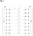
- Figure 1 shows schematically the structure of an embodiment of the optical sensor according to the invention in the form of a light curtain 1 for detecting objects within a monitoring area.
- the light curtain 1 has a transmitter unit with a housing 2a with a series arrangement of transmitters 4 emitting light beams 3 and optical units 5 assigned to them.
- the optical units 5 serve to stretch the light beams 3 emitted by the transmitters 4.
- the optical units 5 are designed identically.
- the light curtain 1 has a receiver unit with a second housing 2b with a series arrangement of receivers 6 receiving light beams 3, each of which is preceded by an optical unit 7.
- the optical units 7 are identical and serve to shape the beams and focus the light beams 3 guided to the receivers 6.
- the housings 2a, 2b are arranged on opposite edges of the monitoring area in such a way that a receiver 6 is arranged opposite a transmitter 4 and forms a transmitter-receiver pair with the latter, with the light beams 3 of the transmitter 4 forming a beam axis.
- a receiver 6 is arranged opposite a transmitter 4 and forms a transmitter-receiver pair with the latter, with the light beams 3 of the transmitter 4 forming a beam axis.
- eight beam axes are provided.
- the light curtain 1 can also have a different number of beam axes.
- the light curtain 1 can also be designed as a reflection light curtain.
- all transmitters 4 and receivers 6 are arranged in a housing which is located at one edge of the monitoring area. At the other end there is a reflector. When the monitoring area is clear, the light beams 3 from the transmitters 4 are guided back to the respective assigned receiver 6 via the reflector.
- the transmitters 4 are controlled by a transmitter control 8.
- An evaluation unit 9 is assigned to the receivers 6.
- the beam axes are activated cyclically one after the other.
- the evaluation unit 9 controls the receivers 6 and evaluates their received signals to generate an object detection signal in the form of a binary switching signal, the switching states of which indicate whether an object is in the monitoring area or not.
- the light beams 3 of the beam axes reach the receiver 6 of the respective beam axis unhindered. If an object is interfered with, at least one beam axis is interrupted.
- the evaluation unit 9 can have a multi-channel structure if the light curtain 1 forms a safety sensor.
- FIG. 2 shows in a highly schematic form an embodiment of the receiving-side optical unit 7.
- the transmitter-side optical units 5 have a corresponding, ie identical, structure.
- the optical unit 7 has a conical, opaque tube 10 whose longitudinal axis runs along the optical axis A of the receiver 6.
- All receivers 6 of the light curtain 1 are arranged on a circuit board 11. All tubes 10 are attached to the circuit board (11) with fastening means (not shown). The fastening means are formed by locking or clip means which are formed in one piece with the tube 10.
- the tube 10 consists of two tube elements 12a, 12b, which can be joined together along a forming direction B running transversely to the optical unit 7.
- the tube elements 12a, 12b each consist of a plastic injection-molded part.
- the tube elements 12a, 12b each extend in the circumferential direction over an angular range of slightly more than 180° and are joined together in an overlapping manner in the forming direction B so that their edge areas overlap.
- the tube elements 12a, 12b are fastened to one another using fixing means (not shown).
- the fixing means are components of the tube elements 12a, 12b and in the present case are formed in the form of clip connections.
- a diaphragm 13 In a first element plane, which forms a lens plane and runs along the upper edge of the tube 10, a diaphragm 13 is provided, the circular diaphragm opening 13a of which is arranged symmetrically to the optical axis.
- This diaphragm 13 is part of the first tube element 12a, and is formed in one piece with the tube element 12a.
- the diaphragm 13 can also be an insert that can be placed in the tube 10, in which case corresponding receiving segments are provided on the tube elements 12a, 12b.
- intermediate diaphragms 14, 15 are provided, each with a diaphragm opening 14a, 15a.
- the intermediate diaphragm 14 is part of the tube element 12b
- the intermediate diaphragm 15 is part of the tube element 12a.
- a field stop 16 with a diaphragm opening 16a is provided on the lower edge of the tube 10 facing the receiver 6.
- the field stop 16 is arranged on the tube element 12b.
- the diameters of the apertures 13a, 14a, 15a, 16a of the individual apertures 13, 14, 15, 16 become larger from the lower edge to the upper edge, as can be seen from Figure 2 visible.
- the optical unit 7 comprises three lenses 17a-c as additional optical elements. These lenses 17a-c are mounted in element planes in the tube 10 that form lens planes. The lenses 17 ac form inserts that are inserted into the tube 10. To fix the position of the lenses 17a-c, receiving segments are provided on the inner wall of the tube 10.
- the lenses 17a-c consist of a plastic injection-molded part.
- the lenses 17a-c are connected via flexible webs 18a, 18b, which form the plastic injection-molded part with the lenses 17a-c.
- the flexible webs 18a, 18b are advantageously formed in the form of film joints.
- the flexibility of the webs 18a, 18b can be maintained by material constrictions that are predetermined in the plastic injection molded parts.
- Figure 3 shows a further development of the lens arrangement according to Figure 2.
- Figure 3 shows a multiple arrangement of lenses 17a-c for tubes 10 of a transmitting or receiving side series arrangement.
- a lens arrangement with three lenses 17a-c is provided according to the embodiment according to Figure 2 are provided, these being connected by the webs 18a, 18b.
- the lens arrangements for adjacent tubes 10 are connected to further flexible webs 19, which are designed in accordance with the webs 18a, 18b.
- the lens arrangements for all tubes 10 can be formed from a plastic injection-molded part.
- Figure 3 shows a lens arrangement for four tubes 10, whereby the number of lens arrangements can of course also be adapted to a different number of tubes 10.
- FIGS. 4a, 4b show another example of an optical unit 7. This again has a tube 10 consisting of two tube elements 12a, 12b, which can be joined together in the forming direction B.
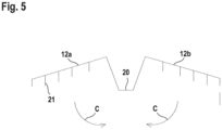
- the embodiment according to the Figures 4a, 4b differs from the embodiment of the Figure 2 in that the tube elements 12a, 12b are connected by film joints 20 ( Figure 5 ).
- the tube elements 12a, 12b with the film joints 20 are formed from only one plastic injection-molded part.
- the film joints 20 are flexible, ie bendable, which is achieved by suitable perforations or material constrictions.
- the tube elements 12a, 12b can be folded in the directions C.
- the tube elements 12a, 12b are folded in accordance with the embodiment according to Figure 2 connected to tube 10.
- the diaphragm 13 with the diaphragm opening 13a is again located in the area of the upper edge of the tube 10, in which the film joints 20 are arranged.
- the field stop 16 with the aperture 16a is again located at the lower edge of the tube 10.
- the optical unit 7 according to the Figures 4a, 4b has as an optical element a lens 17 in a lens plane.
- Microstructures 21 are provided on the light traps, which prevent obliquely incident light from reaching the receiver 6.
Landscapes
- Physics & Mathematics (AREA)
- General Physics & Mathematics (AREA)
- Life Sciences & Earth Sciences (AREA)
- General Life Sciences & Earth Sciences (AREA)
- Geophysics (AREA)
- Electromagnetism (AREA)
- Engineering & Computer Science (AREA)
- Computer Networks & Wireless Communication (AREA)
- Radar, Positioning & Navigation (AREA)
- Remote Sensing (AREA)
- Geophysics And Detection Of Objects (AREA)
Description
- Die Erfindung betrifft einen optischen Sensor.
- Derartige optische Sensoren werden generell zur Erfassung von Objekten in einem Überwachungsbereich eingesetzt.
- In der einfachsten Ausführungsform weist der optische Sensor nur einen Lichtstrahlen emittierenden Sender und einen Lichtstrahlen empfangenden Empfänger auf. Der optische Sensor kann dabei als Lichttaster, Distanzsensor oder Reflexionslichtschranke und dergleichen ausgebildet sein, wobei bei diesen Ausführungsformen der Sender und der Empfänger in einem gemeinsamen Gehäuse integriert sind. Weiterhin kann der optische Sensor auch als Lichtschranke ausgebildet sein. In diesem Fall sind der Sender und Empfänger in separaten Gehäusen untergebracht.
- Generell kann der optische Sensor auch mehrere Sender und/oder Empfänger aufweisen. Ein Beispiel für einen derartigen optischen Sensor ist ein Lichtvorhang.
- Der Lichtvorhang umfasst typischerweise in einem ersten Gehäuse an einem Rand des Überwachungsbereichs eine Reihenanordnung von Lichtstrahlen emittierenden Sendern und in einem zweiten Gehäuse an dem gegenüberliegenden Rand des Überwachungsbereichs eine Reihenanordnung von Lichtstrahlen empfangenden Empfängern.
- Der optische Sensor weist eine Auswerteeinheit auf, in welcher in Abhängigkeit von Empfangssignalen des oder der Empfänger ein Objektfeststellungssignal generiert wird. Dieses Objektfeststellungssignal kann insbesondere als binäres Schaltsignal ausgebildet sein, dessen Schaltzustände angeben, ob sich ein Objekt im Überwachungsbereich befindet oder nicht. Das Objektfeststellungssignal kann alternativ ein analoges Signal, beispielsweise ein Distanzwert sein.
- Um eine sichere Objektdetektion zu gewährleisten, ist jedem Sender sowie jedem Empfänger eine Optikeinheit zugeordnet, die insbesondere Optikelemente, wie z. B. Linsen, aufweist. Mit diesen Optikeinheiten erfolgt eine sendeseitige Strahlformung der Lichtstrahlen und empfangsseitig eine Fokussierung der Lichtstrahlen auf den jeweiligen Empfänger.
- Trotz des Einsatzes derartiger Optikeinheiten besteht ein häufiges Problem bei derartigen optischen Sensoren darin, dass die Lichtstrahlen nicht genau entlang der optischen Achse des Senders emittiert werden, sondern dass zusätzlich Nebenkeulen im Strahlprofil vorhanden sind. Weiterhin entstehen Nebenkeulen durch parasitäre Reflexionen von Teilen der Lichtstrahlen innerhalb des j eweiligen Gehäuses des optischen Sensors. Dies kann zu Beeinträchtigungen der Objektdetektionen führen, d. h. die Nachweissicherheit bei den Objektdetektionen ist reduziert.
- Ein weiterer Nachteil besteht darin, dass bekannte optische Sensoren konstruktiv aufwändiger sind.
- Die
DE 20 2007 010 493 U1 betrifft ein Gehäuse für eine optoelektronische Sensoranordnung mit wenigstens einem Lichtsender und/oder einem Lichtempfänger, welches als im wesentlichen zylindrisches Hohlprofil mit einer Frontseite, einer Bodenseite, einer ersten Seitenwand und einer zweiten Seitenwand ausgebildet und aus genau einem ersten Element und einem zweiten Element zusammengesetzt ist. Das erste Element umfasst wenigstens die erste Seitenwand. Das zweite Element umfasst wenigstens die zweite Seitenwand. - Die
DE 20 2020 100 208 U1 betrifft einen optoelektronischen Sensor mit mindestens einem Sendeelement und mindestens einem Empfangselement und mindestens einem Tubus vor dem Sendeelement, wobei der Tubus eine lichtabsorbierende Oberfläche aufweist. Die lichtabsorbierende Oberfläche ist durch ein dunkles thermoplastisches Elastomer mit einer matten Oberfläche gebildet. - In der
US 6 175 106 B1 ist ein optischer Sensor beschrieben. Dieser optische Sensor ist in Form eines Lichtgitters ausgebildet. Das Lichtgitter umfasst eine optische Anordnung mit einer Vielzahl von Licht aussendenden Sendeelementen bzw. Empfangselementen, einer Vielzahl von diffraktiven/refraktiven optischen Elementen und einer transparenten Frontabdeckung, insbesondere einer Frontscheibe. Die diffraktiven/refraktiven optischen Elemente sind auf einem einheitlichen, einstückig ausgebildeten Trägerelement angeordnet. Das Trägerelement wird durch die Frontabdeckung gebildet, wobei die diffraktiven/refraktiven optischen Elemente unmittelbar in der Frontabdeckung ausgebildet, insbesondere in diese eingeprägt oder eingegossen sind. Die Sende- bzw. Empfangselemente sind auf einer einheitlichen, einstückig ausgebildeten Leiterplatte angeordnet. - Die
DE 20 2007 011 016 U1 betrifft einen optischen Sensor zur Erfassung von Objekten in einem Überwachungsbereich, mit wenigstens einem Sendelichtstrahlen emittierenden Sender und wenigstens einem Empfangslichtstrahlen empfangenden Empfänger. Der Sender und/oder Empfänger ist jeweils in einem einstückig ausgebildeten Blendentubus gelagert ist, wobei erste Teile des Blendentubus eine Lichtfalle bilden und weitere Teile zur Lagerung einer Optik und/oder zur Ausbildung einer Blende vorgesehen sind. - Die
US 2021/0215804 A1 betrifft einen Sensor mit einem Optikmodul, das an einem Gehäuse drehbar gelagert ist. Das Optikmodul umfasst einen Sender und Empfänger, die in einem Tubus gelagert sind. - Der Erfindung liegt die Aufgabe zugrunde, einen optischen Sensor der eingangs genannten Art bereitzustellen, bei welchem mit geringem Herstellungsaufwand die Nachweissicherheit erhöht ist.
- Zur Lösung dieser Aufgabe sind die Merkmale des Anspruchs 1 vorgesehen. Vorteilhafte Ausführungsformen und zweckmäßige Weiterbildungen der Erfindung sind in den abhängigen Ansprüchen beschrieben.
- Die Erfindung betrifft einen optischen Sensor zur Erfassung von Objekten in einem Überwachungsbereich mit wenigstens einem eine optische Achse aufweisenden Lichtstrahlen emittierenden Sender und mit wenigstens einem eine optische Achse aufweisenden Empfänger, welcher zum Empfang von Lichtstrahlen ausgebildet ist. Dem Sender und dem Empfänger ist jeweils ein Tubus zugeordnet, dessen Längsachse in Richtung der optischen Achse des Senders oder Empfängers verläuft. Der Tubus besteht aus mehreren Tubuselementen, die quer zur optischen Achse zum Tubus gefügt werden können. Der Tubus bildet wenigstens eine Elementebene, in der ein Optikelement vorhanden ist, aus. Der Tubus weist eine oder mehrere Elementebenen in Form von Blendenebenen auf, in welchen jeweils eine Blende vorhanden ist, wobei jede Blende Bestandteil der Tubuselemente ist. Die Tubuselemente des Tubus sind über ein oder mehrere flexible Gelenke verbunden.
- Der erfindungsgemäße optische Sensor kann generell nur einen Sender und nur einen Empfänger aufweisen, wobei dann der optische Sensor als Lichtschranke, Reflexionslichtschranke, Lichttaster, Distanzsensor oder dergleichen ausgebildet ist. Der optische Sensor kann auch eine Mehrfachanordnung von Sendern und/oder Empfängern aufweisen. Insbesondere kann der optische Sensor als Lichtvorhang ausgebildet sein.
- Die Funktionsweise des optischen Sensors ist generell derart, dass der optische Sensor eine Auswerteeinheit aufweist, in der abhängig von Empfangssignalen des oder der Empfänger ein Objektfeststellungssignal generiert, welches angibt, ob ein Objekt im Überwachungsbereich vorhanden ist.
- Der optische Sensor kann generell als Sicherheitssensor ausgebildet sein. Für den Einsatz im Bereich der Sicherheitstechnik weist dieser einen fehlersicheren Aufbau auf, was beispielsweise durch eine zweikanalige Auswerteeinheit realisiert wird.
- Erfindungsgemäß ist jedem Sender und jedem Empfänger ein Tubus zugeordnet, welcher aus mehreren Tubuselementen besteht. Der sendeseitige und der empfangsseitige Tubus können identisch ausgebildet sein, was jedoch nicht zwingend ist.
- Ein wesentlicher Aspekt der Erfindung besteht darin, dass die Tubuselemente zur Montage des Tubus quer zur Optikeinheit gefügt, d. h. zusammengesetzt und miteinander verbunden werden. Diese Montage ist nicht nur einfach durchführbar. Vielmehr ermöglicht dies eine einfache Integration von Optikelementen in dem Tubus. Die Optikelemente sind in verschiedenen Elementebenen im Tubus integriert, wobei die Elementebenen vorteilhaft senkrecht zur optischen Achse orientiert. Die einzelnen Tubuselemente weisen Aufnahmesegmente für die Optikelemente, die in Form von Hohlräumen mit Hinterschnittstrukturen ausgebildet sein können. Die Optikelemente können in diese Aufnahmesegmente eingelegt werden, wobei nach Zusammenfügen der Tubuselemente zum Tubus sich die Aufnahmesegmente zu einer in Umfangsrichtung des Tubus umlaufenden Aufnahme ergänzen, in der das jeweilige Optikelement gelagert ist.
- Ein wesentlicher Vorteil besteht weiter darin, dass damit die Anzahl und die Ausbildungen der Optikelemente im Tubus flexibel vorgegeben werden, wodurch die optischen Eigenschaften der so gebildeten Optikeinheit optimiert werden können. Dabei können ohne weiteres auch komplexe optische Sensoren realisiert werden. Insbesondere ist es damit möglich, optische Störungen infolge von Nebenkeulen der Lichtstrahlen zu eliminieren oder zumindest zu reduzieren.
- Dadurch wird mit geringem konstruktivem Aufwand eine hohe Nachweissicherheit bei den mit dem optischen Sensor durchgeführten Objektdetektionen erhalten.
- Gemäß einer vorteilhaften Ausführungsform sind die Tubuselemente des Tubus in Form von Kunststoff-Spritzgussteilen ausgebildet.
- Das Gießen der die Tubuselemente bildenden Kunststoff-Spritzgussteile ist deshalb einfach durchführbar, da sich die Turbuselemente nur über einen Teilwinkelbereich des genannten Tubus erstrecken und dadurch keine geschlossenen Hohlkörper bilden, sondern offene Strukturen, an welchen insbesondere die Aufnahmesegmente in Form von Hohlräumen begrenzenden Hinterschnittstrukturen freiliegen. Die so ausgebildeten Tubuselemente können rationell als Kunststoff-Spritzgussteile hergestellt werden.
- Besonders vorteilhaft sind die Tubuselemente überlappend zum Tubus zusammengeführt.
- Dies gewährleistet eine durchgehend lichtdichte Wand des Tubus, was z. B. bei einer Stoss-an-Stoss-Verbindung der einzelnen Tubuselemente nicht sicher gewährleistet ist, da dort aufgrund von Bauteiltoleranzen schmale Schlitze zwischen den Tubuselementen verbleiben können, durch die Licht durchbrechen kann.
- Um den Tubus aus dem Tubuselement zu bilden, sind vorteilhaft Fixiermittel vorgesehen, mittels derer Tubuselemente verbindbar sind.
- Besonders zweckmäßig sind die Fixiermittel von Clips-Verbindungen gebildet.
- Damit wird eine einfache, werkzeuglose Montage des Tubus ermöglicht. Die Fixiermittel sind vorteilhaft Bestandteil des oder der den Tubus bildenden Tubuselemente, so dass diese ohne Zusatzaufwand mit den Tubuselementen als Kunststoff-Spritzgussteil gefertigt werden können.
- Weiterhin vorteilhaft weist der oder jeder Tubus Befestigungsmittel zur Befestigung an einer Unterlage auf.
- Insbesondere ist die Unterlage von einer Leiterplatte gebildet, auf der Sender und/oder Empfänger angeordnet sind.
- Vorteilhaft sind die Befestigungsmittel als Rast- oder Clips-Mittel ausgebildet.
- Damit kann der Tubus werkzeuglos an der Unterlage befestigt werden. Zudem können die Befestigungsmittel in das oder die den Tubus bildenden Kunststoff-Spritzgussteil integriert sein, so dass kein zusätzlicher Fertigungsaufwand zur Herstellung der Befestigungsmittel entsteht.
- Erfindungsgemäß weist der Tubus eine oder mehrere Elementebenen in Form von Blendenebenen auf, in welchen jeweils eine Blende vorhanden ist.
- Erfindungsgemäß ist die oder jede Blende Bestandteil des Tubus.
- Besteht der Tubus aus einem oder mehreren Kunststoff-Spritzgussteilen kann die Blende Bestandteil dieser Kunststoff-Spritzgussteile sein, wodurch die Blende rationell hergestellt werden kann.
- Die Funktionalität des erfindungsgemäßen Tubus kann vorteilhaft dadurch noch erweitert sein, dass die Innenwand des Tubus Lichtfallen bildende Mikrostrukturen aufweist.
- Dadurch werden unkontrollierte Lichtreflexionen an der Innenwand des Tubus noch besser unterbunden.
- Gemäß einer besonders vorteilhaften Ausführungsform ist der optische Sensor als Lichtvorhang ausgebildet.
- In diesem Fall weist der Lichtvorhang eine Reihenordnung von Sendern auf, wobei jedem Sender ein Tubus zugeordnet ist. Diese Tuben bilden eine senderseitige Tubenanordnung. Der Lichtvorhang weist eine Reihenanordnung von Empfängern auf, wobei jedem Empfänger ein Tubus zugeordnet ist. Diese Tuben bilden eine empfangsseitige Tubenanordnung.
- Besonders vorteilhaft ist, dass in den Tuben der sende- und/oder empfangsseitigen Tubenanordnung jeweils eine Linsenanordnung vorhanden ist. Die Linsen der Linsenanordnung und benachbarte Linsenanordnungen für die sende- oder empfangsseitige Tubenanordnung sind über flexible Stege verbunden.
- Damit kann in nur einem Fertigungsschritt die gesamte Linsenanordnung für die Tuben aller Sender bzw. Empfänger hergestellt werden.
- Die Erfindung wird im Folgenden anhand der Zeichnungen erläutert. Es zeigen:
- Figur 1:
- Ausführungsbeispiel des erfindungsgemäßen optischen Sensors in Form eines Lichtvorhangs.
- Figur 2:
- Ausführungsbeispiel einer Optikeinheit für einen Empfänger des Lichtvorhangs gemäß
Figur 1 . - Figur 3:
- Ausführungsbeispiel einer Linsenanordnung für eine Reihenanordnung von Optikeinheiten gemäß
Figur 2 . - Figur 4:
- Weiteres Ausführungsbeispiel einer Optikeinheit für den Lichtvorhang gemäß
Figur 1 .- a) Schnittdarstellung
- b) Draufsicht von oben
- Figur 5:
- Einzeldarstellung des Tubus der Optikeinheit gemäß den
Figuren 4a, 4b . -
Figur 1 zeigt schematisch den Aufbau eines Ausführungsbeispiels des erfindungsgemäßen optischen Sensors in Form eines Lichtvorhangs 1 zur Erfassung von Objekten innerhalb eines Überwachungsbereichs. - Der Lichtvorhang 1 weist eine Sendereinheit mit einem Gehäuse 2a mit einer Reihenanordnung von Lichtstrahlen 3 emittierenden Sendern 4 und diesen zugeordneten Optikeinheiten 5 auf. Die Optikeinheiten 5 dienen zur Streckformung der von den Sendern 4 emittierten Lichtstrahlen 3. Die Optikeinheiten 5 sind identisch ausgebildet.
- Weiterhin weist der Lichtvorhang 1 eine Empfängereinheit mit einem zweiten Gehäuse 2b mit einer Reihenanordnung von Lichtstrahlen 3 empfangenden Empfängern 6 auf, welchen jeweils eine Optikeinheit 7 vorgeordnet ist. Die Optikeinheiten 7 sind identisch ausgebildet und dienen zur Strahlformung und Fokussierung der auf die Empfänger 6 geführten Lichtstrahlen 3.
- Die Gehäuse 2a, 2b sind an gegenüberliegenden Rändern des Überwachungsbereichs so angeordnet, dass jeweils ein Empfänger 6 einem Sender 4 gegenüberliegend angeordnet ist und mit diesem ein Sender-Empfänger-Paar bildet, wobei die Lichtstrahlen 3 des Senders 4 eine Strahlachse bilden. Im vorliegenden Fall sind acht Strahlachsen vorgesehen. Natürlich kann der Lichtvorhang 1 auch eine andere Zahl von Strahlachsen aufweisen.
- Alternativ kann der Lichtvorhang 1 auch als Reflexions-Lichtvorhang ausgebildet sein. Dann sind alle Sender 4 und Empfänger 6 in einem Gehäuse angeordnet, welcher an einem Rand des Überwachungsbereichs angeordnet ist. Am anderen Ende befindet sich ein Reflektor. Bei freiem Überwachungsbereich werden die Lichtstrahlen 3 der Sender 4 über den Reflektor zurück zum jeweils zugeordneten Empfänger 6 geführt.
- Die Sender 4 werden von einer Sendersteuerung 8 gesteuert. Den Empfängern 6 ist eine Auswerteeinheit 9 zugeordnet. Dabei werden die Strahlachsen zyklisch einzeln nacheinander aktiviert. Die Auswerteeinheit 9 steuert die Empfänger 6 an und wertet deren Empfangssignale zur Generierung eines Objektfeststellungssignals in Form eines binären Schaltsignals aus, dessen Schaltzustände angeben, ob sich ein Objekt im Überwachungsbereich befindet oder nicht. Bei freiem Überwachungsbereich gelangen die Lichtstrahlen 3 der Strahlachsen ungehindert zum Empfänger 6 der jeweiligen Strahlachse. Bei einem Objekteingriff wird wenigstens eine Strahlachse unterbrochen. Die Auswerteeinheit 9 kann einen mehrkanaligen Aufbau aufweisen, falls der Lichtvorhang 1 einen Sicherheitssensor bildet.
-
Figur 2 zeigt in stark schematisierter Form ein Ausführungsbeispiel der empfangsseitigen Optikeinheit 7. Die senderseitigen Optikeinheiten 5 weisen einen hierzu entsprechenden, d. h. identischen Aufbau auf. - Die Optikeinheit 7 weist einen konischen, lichtundurchlässigen Tubus 10 auf, dessen Längsachse entlang der optischen Achse A des Empfängers 6 verläuft.
- Alle Empfänger 6 des Lichtvorhangs 1 sind auf einer Leiterplatte 11 angeordnet. Alle Tuben 10 sind mit nicht dargestellten Befestigungsmitteln an der Leiterplatte (11) befestigt. Die Befestigungsmittel sind von Rast- oder Clips-Mitteln gebildet, die einstückig mit dem Tubus 10 ausgebildet sind.
- Der Tubus 10 besteht aus zwei Tubuselementen 12a, 12b, die entlang einer quer zur Optikeinheit 7 verlaufenden Formungsrichtung B aneinander fügbar sind. Die Tubuselemente 12a, 12b bestehen jeweils aus einem Kunststoff-Spritzgussteil.
- Die Tubuselemente 12a, 12b erstrecken sich in Umfangsrichtung jeweils über einen Winkelbereich von etwas mehr als 180° und werden überlappend in der Formungsrichtung B aneinandergefügt, so dass sich deren Randbereiche überlappen. Die Tubuselemente 12a, 12b werden mit nicht dargestellten Fixiermitteln aneinander befestigt. Die Fixiermittel sind Bestandteile der Tubuselemente 12a, 12b und sind im vorliegenden Fall in Form von Clips-Verbindungen gebildet.
- Bei dem Tubus 10 gemäß
Figur 2 sind mehrere senkrecht zur optischen Achse verlaufende Elementebenen vorgesehen, in welchen Optikelemente gelagert sind. - In einer ersten Elementebene, die eine Linsenebene bildet und die am oberen Rand des Tubus 10 verläuft ist eine Blende 13 vorgesehen, deren kreisförmige Blendenöffnung 13a symmetrisch zur optischen Achse angeordnet ist. Diese Blende 13 ist Bestandteil des ersten Tubuselements 12a, wobei diese einstückig mit dem Tubuselement 12a ausgebildet ist. Alternativ kann die Blende 13 auch ein Einlegeteil sein, das in den Tubus 10 eingelegt werden kann, wobei dann an den Tubuselementen 12a, 12b entsprechende Aufnahmesegmente vorgesehen sind.
- Weiterhin sind zwei Zwischenblenden 14, 15 mit jeweils einer Blendenöffnung 14a, 15a vorgesehen. Die Zwischenblende 14 ist Bestandteil des Tubuselements 12b, die Zwischenblende 15 ist Bestandteil des Tubuselements 12a.
- Schließlich ist am unteren, dem Empfänger 6 zugewandten, Rand des Tubus 10 eine Feldblende 16 mit einer Blendenöffnung 16a vorgesehen. Die Feldblende 16 ist am Tubuselement 12b angeordnet.
- Die Durchmesser der Blendenöffnungen 13a, 14a, 15a, 16a der einzelnen Blenden 13, 14, 15, 16 werden vom unteren Rand zum oberen Rand größer, wie aus
Figur 2 ersichtlich. - Die Optikeinheit 7 gemäß
Figur 2 umfasst als weitere Optikelemente drei Linsen 17a-c. Diese Linsen 17a-c sind in Linsenebenen bildenden Elementebenen im Tubus 10 gelagert. Dabei bilden die Linsen 17 a-c Einlegteile, die in den Tubus 10 eingelegt werden. Zur Lagefixierung der Linsen 17a-c sind an der Innenwand des Tubus 10 Aufnahmesegmente vorgesehen. - Die Linsen 17a-c bestehen im vorliegenden Fall aus einem Kunststoff-Spritzgussteil. Hierzu sind die Linsen 17a-c über flexible Stege 18a, 18b verbunden, die mit den Linsen 17a-c das Kunststoff-Spritzgussteil bilden.
- Die flexiblen Stege 18a, 18b sind vorteilhaft in Form von Filmgelenken gebildet. Die Flexibilität der Stege 18a, 18b kann durch Materialeinschnürungen, die im Kunststoff-Spritzgussteilen vorgegeben sind, erhalten werden.
-
Figur 3 zeigt eine Weiterbildung der Linsenanordnung gemäßFigur 2. Figur 3 zeigt eine Mehrfachanordnung von Linsen 17a-c für Tuben 10 einer sende- oder empfangsseitigen Reihenanordnung. Für jeden Tubus 10 ist eine Linsenanordnung mit drei Linsen 17a-c entsprechend der Ausführungsform gemäßFigur 2 vorgesehen, wobei diese jeweils durch die Stege 18a, 18b verbunden sind. Die Linsenanordnungen für benachbarte Tuben 10 sind mit weiteren flexiblen Stegen 19 verbunden, die entsprechend den Stegen 18a, 18b ausgebildet sind. Auf diese Weise können die Linsenanordnungen für alle Tuben 10 aus einem Kunststoff-Spritzgussteil gebildet sein.Figur 3 zeigt eine Linsenanordnung für vier Tuben 10, wobei die Anzahl der Linsenanordnung natürlich auch an eine andere Anzahl von Tuben 10 anpassbar ist. - Die
Figuren 4a, 4b zeigen ein weiteres Beispiel einer Optikeinheit 7. Die weist wieder einen Tubus 10 bestehend aus zwei Tubuselemente 12a, 12b auf, die in der Formungsrichtung B zusammengefügt werden können. - Die Ausführungsform gemäß den
Figuren 4a, 4b unterscheidet sich von der Ausführungsform derFigur 2 dadurch, dass die Tubuselemente 12a, 12b durch Filmgelenke 20 verbunden sind (Figur 5 ). Die Tubuselemente 12a, 12b mit den Filmgelenken 20 sind von nur einem Kunststoff-Spritzgussteil gebildet. Die Filmgelenke 20 sind im Gegensatz zu den Tubuselementen 12a, 12b flexibel, d. h. biegbar, was durch geeignete Perforationen oder Materialeinschnürungen erzielt wird. - Wie
Figur 5 zeigt, können die Tubuselemente 12a, 12b in den Richtungen C zusammengefaltet werden. Dazu werden die Tubuselemente 12a, 12b entsprechend der Ausführungsform gemäßFigur 2 zum Tubus 10 verbunden. - Im Bereich des oberen Randes des Tubus 10, in dem die Filmgelenke 20 angeordnet sind, befindet sich wieder die Blende 13 mit der Blendenöffnung 13a. In weiterer Übereinstimmung mit der Ausführungsform gemäß
Figur 2 befindet sich am unteren Rand des Tubus 10 wieder die Feldblende 16 mit der Blendenöffnung 16a. - Die Optikeinheit 7 gemäß den
Figuren 4a, 4b weist als Optikelement eine Linse 17 in einer Linsenebene auf. - In Erweiterung zur Ausführungsform gemäß
Figur 2 sind drei der Ausführungsformen derFiguren 4a, 4b an den Lichtfallen bildende Mikrostrukturen 21 vorgesehen, die verhindern, dass schräg einfallendes Licht zum Empfänger 6 gelangt. -
- (1)
- Lichtvorhang
- (2a,b)
- Gehäuse
- (3)
- Lichtstrahl
- (4)
- Sender
- (5)
- Optikeinheit
- (6)
- Empfänger
- (7)
- Optikeinheit
- (8)
- Sendersteuerung
- (9)
- Auswerteeinheit
- (10)
- Tubus
- (11)
- Leiterplatte
- (12a,b)
- Tubuselement
- (13)
- Blende
- (13a)
- Blendenöffnung
- (14)
- Zwischenblende
- (14a)
- Blendenöffnung
- (15)
- Zwischenblende
- (15a)
- Blendenöffnung
- (16)
- Feldblende
- (16a)
- Blendenöffnung
- (17)
- Linse
- (17a-c)
- Linse
- (18a,b)
- Steg
- (19)
- Steg
- (20)
- Filmgelenk
- (21)
- Mikrostruktur
- (A)
- Optische Achse
- (B)
- Formungsrichtung
Claims (14)
- Optischer Sensor zur Erfassung von Objekten in einem Überwachungsbereich mit wenigstens einem eine optische Achse (A) aufweisenden, Lichtstrahlen emittierenden Sender (4) und mit wenigstens einem eine optische Achse (A) aufweisenden Empfänger, (6) welcher zum Empfang von Lichtstrahlen (3) ausgebildet ist, wobei dem Sender (4) und dem Empfänger (6) jeweils ein Tubus (10) zugeordnet ist, dessen Längsachse in Richtung der optischen Achse des Senders (4) oder Empfängers (6) verläuft, wobei der Tubus (10) aus mehreren Tubuselementen (12a, 12b) besteht, die quer zur optischen Achse zum Tubus (10) gefügt werden können, und wobei der Tubus (10) wenigstens eine Elementebene, in der ein Optikelement vorhanden ist, ausbildet, wobei der Tubus (10) eine oder mehrere Elementebenen in Form von Blendenebenen (14, 15) aufweist, in welchen jeweils eine Blende (13) vorhanden ist und wobei die oder jede Blende (13) Bestandteil der Tubuselemente (12a, 12b) ist, dadurch gekennzeichnet, dass die Tubuselemente (12a, 12b) des Tubus 10 über ein oder mehrere flexible Gelenke verbunden sind.
- Optischer Sensor nach Anspruch 1, dadurch gekennzeichnet, dass die Tubuselemente (12a, 12b) des Tubus (10) in Form von Kunststoff-Spritzgussteilen ausgebildet sind.
- Optischer Sensor nach einem der Ansprüche 1 oder 2, dadurch gekennzeichnet, dass Fixiermittel vorgesehen sind, mittels derer die Tubuselemente (12a, 12b) verbindbar sind.
- Optischer Sensor nach einem der Ansprüche 1 bis 3, dadurch gekennzeichnet, dass der oder jeder Tubus (10) Befestigungsmittel zur Befestigung an einer Unterlage aufweist.
- Optischer Sensor nach Anspruch 4, dadurch gekennzeichnet, dass die Befestigungsmittel als Rast- oder Clips-Mittel ausgebildet sind.
- Optischer Sensor nach einem der Ansprüche 4 oder 5, dadurch gekennzeichnet, dass die Unterlage von einer Leiterplatte (11) gebildet ist, auf der Sender (4) und/oder Empfänger (6) angeordnet sind.
- Optischer Sensor nach einem der Ansprüche 1 bis 6, dadurch gekennzeichnet, dass jede Blende (13, 16) eine Blendenöffnung zumindest teilweise umschließt.
- Optischer Sensor nach einem der Ansprüche 1 bis 7, dadurch gekennzeichnet, dass Blenden (13, 16) in Form von Zwischenblenden (14, 15) vorhanden sind.
- Optischer Sensor nach Anspruch 8, dadurch gekennzeichnet, dass Blenden (13, 16) oder Zwischenblenden (14, 15) höhenversetzt sind.
- Optischer Sensor nach Anspruch 9, dadurch gekennzeichnet, dass höhenversetzte Blenden (13, 16) oder Zwischenblenden (14, 15) überlappen.
- Optischer Sensor nach einem der Ansprüche 1 bis 10, dadurch gekennzeichnet, dass die Innenwand des Tubus (10) Lichtfallen bildende Mikrostrukturen (21) aufweist.
- Optischer Sensor nach einem der Ansprüche 1 bis 11, dadurch gekennzeichnet, dass dieser ein Lichtvorhang (1) ist.
- Optischer Sensor nach Anspruch 12, dadurch gekennzeichnet, dass der Lichtvorhang (1) eine Reihenordnung von Sendern (4) aufweist, wobei jedem Sender (4) ein Tubus (10) zugeordnet ist, wobei diese Tuben (10) eine senderseitige Tubenanordnung bilden, und dass der Lichtvorhang (1) eine Reihenanordnung von Empfängern (6) aufweist, wobei jedem Empfänger (6) ein Tubus (10) zugeordnet ist, wobei diese Tuben (10) eine empfangsseitige Tubenanordnung bilden.
- Optischer Sensor nach einem der Ansprüche 1 bis 13, dadurch gekennzeichnet, dass dieser ein Sicherheitssensor ist.
Priority Applications (1)
| Application Number | Priority Date | Filing Date | Title |
|---|---|---|---|
| EP22185903.6A EP4220239B1 (de) | 2022-01-21 | 2022-01-21 | Optischer sensor |
Applications Claiming Priority (2)
| Application Number | Priority Date | Filing Date | Title |
|---|---|---|---|
| EP22185903.6A EP4220239B1 (de) | 2022-01-21 | 2022-01-21 | Optischer sensor |
| EP22152804.5A EP4215954B1 (de) | 2022-01-21 | 2022-01-21 | Optischer sensor |
Related Parent Applications (2)
| Application Number | Title | Priority Date | Filing Date |
|---|---|---|---|
| EP22152804.5A Division-Into EP4215954B1 (de) | 2022-01-21 | 2022-01-21 | Optischer sensor |
| EP22152804.5A Division EP4215954B1 (de) | 2022-01-21 | 2022-01-21 | Optischer sensor |
Publications (2)
| Publication Number | Publication Date |
|---|---|
| EP4220239A1 EP4220239A1 (de) | 2023-08-02 |
| EP4220239B1 true EP4220239B1 (de) | 2024-12-25 |
Family
ID=80122203
Family Applications (3)
| Application Number | Title | Priority Date | Filing Date |
|---|---|---|---|
| EP22185905.1A Active EP4220240B1 (de) | 2022-01-21 | 2022-01-21 | Optischer sensor |
| EP22185903.6A Active EP4220239B1 (de) | 2022-01-21 | 2022-01-21 | Optischer sensor |
| EP22152804.5A Active EP4215954B1 (de) | 2022-01-21 | 2022-01-21 | Optischer sensor |
Family Applications Before (1)
| Application Number | Title | Priority Date | Filing Date |
|---|---|---|---|
| EP22185905.1A Active EP4220240B1 (de) | 2022-01-21 | 2022-01-21 | Optischer sensor |
Family Applications After (1)
| Application Number | Title | Priority Date | Filing Date |
|---|---|---|---|
| EP22152804.5A Active EP4215954B1 (de) | 2022-01-21 | 2022-01-21 | Optischer sensor |
Country Status (1)
| Country | Link |
|---|---|
| EP (3) | EP4220240B1 (de) |
Families Citing this family (1)
| Publication number | Priority date | Publication date | Assignee | Title |
|---|---|---|---|---|
| DE102023121562B3 (de) | 2023-08-11 | 2024-08-01 | Sick Ag | Optoelektronischer Sensor und Verfahren zur Herstellung eines optoelektronischen Sensors |
Citations (2)
| Publication number | Priority date | Publication date | Assignee | Title |
|---|---|---|---|---|
| EP2019293A1 (de) * | 2007-07-27 | 2009-01-28 | Sick Ag | Gehäuse für eine optoelektronische Sensoranordnung |
| EP3796033A1 (de) * | 2019-09-18 | 2021-03-24 | Apple Inc. | Optisches modul mit streulichtblocker |
Family Cites Families (9)
| Publication number | Priority date | Publication date | Assignee | Title |
|---|---|---|---|---|
| DE19712828A1 (de) * | 1997-03-26 | 1998-10-15 | Sick Ag | Lichtgitter und Verfahren zu seiner Herstellung |
| DE102004012794A1 (de) * | 2004-03-16 | 2005-11-17 | Sick Ag | Lichtgitter |
| DE102005046359A1 (de) * | 2005-09-28 | 2007-03-29 | Sick Ag | Optoelektronische Anordnung |
| DE202007011016U1 (de) * | 2007-08-07 | 2007-10-31 | Leuze Electronic Gmbh & Co Kg | Optischer Sensor |
| DE102009021645B3 (de) * | 2009-05-16 | 2010-11-18 | Sick Ag | Optische Reihenanordnung für Lichtgitter |
| PT2966346T (pt) * | 2015-01-26 | 2017-06-29 | Schreder | Melhorias em arranjos matriciais de lentes ou relacionadas com arranjos matriciais de lentes |
| DE102018207294A1 (de) * | 2018-05-09 | 2019-11-14 | Ibeo Automotive Systems GmbH | LIDAR Messsystem und Verfahren zur Montage eines LIDAR Messsystems |
| CN110832345A (zh) * | 2019-04-15 | 2020-02-21 | 深圳市速腾聚创科技有限公司 | 一种激光雷达 |
| DE202020100208U1 (de) * | 2020-01-16 | 2021-04-19 | Sick Ag | Optoelektronischer Sensor |
-
2022
- 2022-01-21 EP EP22185905.1A patent/EP4220240B1/de active Active
- 2022-01-21 EP EP22185903.6A patent/EP4220239B1/de active Active
- 2022-01-21 EP EP22152804.5A patent/EP4215954B1/de active Active
Patent Citations (2)
| Publication number | Priority date | Publication date | Assignee | Title |
|---|---|---|---|---|
| EP2019293A1 (de) * | 2007-07-27 | 2009-01-28 | Sick Ag | Gehäuse für eine optoelektronische Sensoranordnung |
| EP3796033A1 (de) * | 2019-09-18 | 2021-03-24 | Apple Inc. | Optisches modul mit streulichtblocker |
Also Published As
| Publication number | Publication date |
|---|---|
| EP4220240B1 (de) | 2024-08-28 |
| EP4215954A1 (de) | 2023-07-26 |
| EP4220240A1 (de) | 2023-08-02 |
| EP4220239A1 (de) | 2023-08-02 |
| EP4215954B1 (de) | 2024-08-28 |
Similar Documents
| Publication | Publication Date | Title |
|---|---|---|
| DE102004046725B4 (de) | Gehäuse für ein Lichtgitter | |
| DE102008020171A1 (de) | Optische Sensorvorrichtung | |
| EP2023164B1 (de) | Optischer Sensor | |
| DE202020106752U1 (de) | Sensor | |
| EP4220240B1 (de) | Optischer sensor | |
| EP2019293A1 (de) | Gehäuse für eine optoelektronische Sensoranordnung | |
| EP1907891B1 (de) | Optischer sensor zur erfassung von objekten in einem überwachungsbereich | |
| EP2053428B1 (de) | Optoelektronischer Sensor | |
| EP0807842A2 (de) | Optische Anordnung mit diffraktivem optischen Element | |
| DE102007017909A1 (de) | Optoelektronischer Sensor mit verbundener Doppellinse und Herstellungsverfahren hierfür | |
| DE102019208841A1 (de) | Lötfähiges, insbesondere einstückiges optisches Lichtleitmodul zur Streulichtrauchdetektion sowie Rauchdetektionsblock, Rauchdetektionsmodul und Streulichtrauchmelder | |
| DE202006000742U1 (de) | Optische Sensorvorrichtung | |
| EP4215953A1 (de) | Optischer sensor | |
| DE102023132413A1 (de) | Näherungsschalter mit einer Anzeigevorrichtung | |
| EP1653200B1 (de) | Optischer Sensor | |
| CH709341A1 (de) | Vorrichtung und Verfahren zur Erfassung von Objekten in einem Überwachungsbereich. | |
| DE102007055497B4 (de) | Optischer Sensor für ein Kraftfahrzeug | |
| EP2535743A2 (de) | Optischer sensor | |
| DE102004030777B4 (de) | Gehäuse für einen optischen Sensor | |
| DE102016121913A1 (de) | Mehrstrahllichtschranke | |
| EP2578930B1 (de) | Lichtmodul für eine Außenleuchte | |
| DE20117499U1 (de) | Optischer Sensor | |
| EP1544037A2 (de) | Funktionsanzeigenbeleuchtungsvorrichtung | |
| DE10246945B4 (de) | Fahrzeugleuchte mit Rückstrahlerelement | |
| DE102017012252A1 (de) | Optoelektronisches Sensorsystem |
Legal Events
| Date | Code | Title | Description |
|---|---|---|---|
| PUAI | Public reference made under article 153(3) epc to a published international application that has entered the european phase |
Free format text: ORIGINAL CODE: 0009012 |
|
| STAA | Information on the status of an ep patent application or granted ep patent |
Free format text: STATUS: REQUEST FOR EXAMINATION WAS MADE |
|
| 17P | Request for examination filed |
Effective date: 20220720 |
|
| AC | Divisional application: reference to earlier application |
Ref document number: 4215954 Country of ref document: EP Kind code of ref document: P |
|
| AK | Designated contracting states |
Kind code of ref document: A1 Designated state(s): AL AT BE BG CH CY CZ DE DK EE ES FI FR GB GR HR HU IE IS IT LI LT LU LV MC MK MT NL NO PL PT RO RS SE SI SK SM TR |
|
| STAA | Information on the status of an ep patent application or granted ep patent |
Free format text: STATUS: EXAMINATION IS IN PROGRESS |
|
| 17Q | First examination report despatched |
Effective date: 20240131 |
|
| GRAP | Despatch of communication of intention to grant a patent |
Free format text: ORIGINAL CODE: EPIDOSNIGR1 |
|
| STAA | Information on the status of an ep patent application or granted ep patent |
Free format text: STATUS: GRANT OF PATENT IS INTENDED |
|
| INTG | Intention to grant announced |
Effective date: 20241014 |
|
| GRAS | Grant fee paid |
Free format text: ORIGINAL CODE: EPIDOSNIGR3 |
|
| GRAA | (expected) grant |
Free format text: ORIGINAL CODE: 0009210 |
|
| STAA | Information on the status of an ep patent application or granted ep patent |
Free format text: STATUS: THE PATENT HAS BEEN GRANTED |
|
| AC | Divisional application: reference to earlier application |
Ref document number: 4215954 Country of ref document: EP Kind code of ref document: P |
|
| AK | Designated contracting states |
Kind code of ref document: B1 Designated state(s): AL AT BE BG CH CY CZ DE DK EE ES FI FR GB GR HR HU IE IS IT LI LT LU LV MC MK MT NL NO PL PT RO RS SE SI SK SM TR |
|
| REG | Reference to a national code |
Ref country code: GB Ref legal event code: FG4D Free format text: NOT ENGLISH |
|
| REG | Reference to a national code |
Ref country code: CH Ref legal event code: EP |
|
| REG | Reference to a national code |
Ref country code: DE Ref legal event code: R096 Ref document number: 502022002487 Country of ref document: DE |
|
| REG | Reference to a national code |
Ref country code: IE Ref legal event code: FG4D Free format text: LANGUAGE OF EP DOCUMENT: GERMAN |
|
| REG | Reference to a national code |
Ref country code: LT Ref legal event code: MG9D |
|
| PG25 | Lapsed in a contracting state [announced via postgrant information from national office to epo] |
Ref country code: HR Free format text: LAPSE BECAUSE OF FAILURE TO SUBMIT A TRANSLATION OF THE DESCRIPTION OR TO PAY THE FEE WITHIN THE PRESCRIBED TIME-LIMIT Effective date: 20241225 |
|
| PG25 | Lapsed in a contracting state [announced via postgrant information from national office to epo] |
Ref country code: FI Free format text: LAPSE BECAUSE OF FAILURE TO SUBMIT A TRANSLATION OF THE DESCRIPTION OR TO PAY THE FEE WITHIN THE PRESCRIBED TIME-LIMIT Effective date: 20241225 |
|
| PG25 | Lapsed in a contracting state [announced via postgrant information from national office to epo] |
Ref country code: BG Free format text: LAPSE BECAUSE OF FAILURE TO SUBMIT A TRANSLATION OF THE DESCRIPTION OR TO PAY THE FEE WITHIN THE PRESCRIBED TIME-LIMIT Effective date: 20241225 |
|
| PG25 | Lapsed in a contracting state [announced via postgrant information from national office to epo] |
Ref country code: NO Free format text: LAPSE BECAUSE OF FAILURE TO SUBMIT A TRANSLATION OF THE DESCRIPTION OR TO PAY THE FEE WITHIN THE PRESCRIBED TIME-LIMIT Effective date: 20250325 |
|
| PG25 | Lapsed in a contracting state [announced via postgrant information from national office to epo] |
Ref country code: LV Free format text: LAPSE BECAUSE OF FAILURE TO SUBMIT A TRANSLATION OF THE DESCRIPTION OR TO PAY THE FEE WITHIN THE PRESCRIBED TIME-LIMIT Effective date: 20241225 Ref country code: GR Free format text: LAPSE BECAUSE OF FAILURE TO SUBMIT A TRANSLATION OF THE DESCRIPTION OR TO PAY THE FEE WITHIN THE PRESCRIBED TIME-LIMIT Effective date: 20250326 |
|
| PG25 | Lapsed in a contracting state [announced via postgrant information from national office to epo] |
Ref country code: RS Free format text: LAPSE BECAUSE OF FAILURE TO SUBMIT A TRANSLATION OF THE DESCRIPTION OR TO PAY THE FEE WITHIN THE PRESCRIBED TIME-LIMIT Effective date: 20250325 |
|
| REG | Reference to a national code |
Ref country code: NL Ref legal event code: MP Effective date: 20241225 |
|
| PG25 | Lapsed in a contracting state [announced via postgrant information from national office to epo] |
Ref country code: NL Free format text: LAPSE BECAUSE OF FAILURE TO SUBMIT A TRANSLATION OF THE DESCRIPTION OR TO PAY THE FEE WITHIN THE PRESCRIBED TIME-LIMIT Effective date: 20241225 |
|
| PG25 | Lapsed in a contracting state [announced via postgrant information from national office to epo] |
Ref country code: SM Free format text: LAPSE BECAUSE OF FAILURE TO SUBMIT A TRANSLATION OF THE DESCRIPTION OR TO PAY THE FEE WITHIN THE PRESCRIBED TIME-LIMIT Effective date: 20241225 |
|
| PG25 | Lapsed in a contracting state [announced via postgrant information from national office to epo] |
Ref country code: PL Free format text: LAPSE BECAUSE OF FAILURE TO SUBMIT A TRANSLATION OF THE DESCRIPTION OR TO PAY THE FEE WITHIN THE PRESCRIBED TIME-LIMIT Effective date: 20241225 |
|
| PG25 | Lapsed in a contracting state [announced via postgrant information from national office to epo] |
Ref country code: ES Free format text: LAPSE BECAUSE OF FAILURE TO SUBMIT A TRANSLATION OF THE DESCRIPTION OR TO PAY THE FEE WITHIN THE PRESCRIBED TIME-LIMIT Effective date: 20241225 |
|
| PG25 | Lapsed in a contracting state [announced via postgrant information from national office to epo] |
Ref country code: IS Free format text: LAPSE BECAUSE OF FAILURE TO SUBMIT A TRANSLATION OF THE DESCRIPTION OR TO PAY THE FEE WITHIN THE PRESCRIBED TIME-LIMIT Effective date: 20250425 |
|
| PG25 | Lapsed in a contracting state [announced via postgrant information from national office to epo] |
Ref country code: PT Free format text: LAPSE BECAUSE OF FAILURE TO SUBMIT A TRANSLATION OF THE DESCRIPTION OR TO PAY THE FEE WITHIN THE PRESCRIBED TIME-LIMIT Effective date: 20250428 |
|
| PG25 | Lapsed in a contracting state [announced via postgrant information from national office to epo] |
Ref country code: EE Free format text: LAPSE BECAUSE OF FAILURE TO SUBMIT A TRANSLATION OF THE DESCRIPTION OR TO PAY THE FEE WITHIN THE PRESCRIBED TIME-LIMIT Effective date: 20241225 |
|
| PG25 | Lapsed in a contracting state [announced via postgrant information from national office to epo] |
Ref country code: RO Free format text: LAPSE BECAUSE OF FAILURE TO SUBMIT A TRANSLATION OF THE DESCRIPTION OR TO PAY THE FEE WITHIN THE PRESCRIBED TIME-LIMIT Effective date: 20241225 |
|
| PG25 | Lapsed in a contracting state [announced via postgrant information from national office to epo] |
Ref country code: SK Free format text: LAPSE BECAUSE OF FAILURE TO SUBMIT A TRANSLATION OF THE DESCRIPTION OR TO PAY THE FEE WITHIN THE PRESCRIBED TIME-LIMIT Effective date: 20241225 |
|
| PG25 | Lapsed in a contracting state [announced via postgrant information from national office to epo] |
Ref country code: CZ Free format text: LAPSE BECAUSE OF FAILURE TO SUBMIT A TRANSLATION OF THE DESCRIPTION OR TO PAY THE FEE WITHIN THE PRESCRIBED TIME-LIMIT Effective date: 20241225 |
|
| PG25 | Lapsed in a contracting state [announced via postgrant information from national office to epo] |
Ref country code: IT Free format text: LAPSE BECAUSE OF FAILURE TO SUBMIT A TRANSLATION OF THE DESCRIPTION OR TO PAY THE FEE WITHIN THE PRESCRIBED TIME-LIMIT Effective date: 20241225 |
|
| REG | Reference to a national code |
Ref country code: CH Ref legal event code: PL |
|
| PG25 | Lapsed in a contracting state [announced via postgrant information from national office to epo] |
Ref country code: SE Free format text: LAPSE BECAUSE OF FAILURE TO SUBMIT A TRANSLATION OF THE DESCRIPTION OR TO PAY THE FEE WITHIN THE PRESCRIBED TIME-LIMIT Effective date: 20241225 |
|
| PG25 | Lapsed in a contracting state [announced via postgrant information from national office to epo] |
Ref country code: LU Free format text: LAPSE BECAUSE OF NON-PAYMENT OF DUE FEES Effective date: 20250121 Ref country code: MC Free format text: LAPSE BECAUSE OF FAILURE TO SUBMIT A TRANSLATION OF THE DESCRIPTION OR TO PAY THE FEE WITHIN THE PRESCRIBED TIME-LIMIT Effective date: 20241225 |
|
| P01 | Opt-out of the competence of the unified patent court (upc) registered |
Free format text: CASE NUMBER: UPC_APP_3751_4220239/2025 Effective date: 20250820 |
|
| REG | Reference to a national code |
Ref country code: DE Ref legal event code: R097 Ref document number: 502022002487 Country of ref document: DE |
|
| PG25 | Lapsed in a contracting state [announced via postgrant information from national office to epo] |
Ref country code: DK Free format text: LAPSE BECAUSE OF FAILURE TO SUBMIT A TRANSLATION OF THE DESCRIPTION OR TO PAY THE FEE WITHIN THE PRESCRIBED TIME-LIMIT Effective date: 20241225 |
|
| PG25 | Lapsed in a contracting state [announced via postgrant information from national office to epo] |
Ref country code: BE Free format text: LAPSE BECAUSE OF NON-PAYMENT OF DUE FEES Effective date: 20250131 |
|
| PG25 | Lapsed in a contracting state [announced via postgrant information from national office to epo] |
Ref country code: CH Free format text: LAPSE BECAUSE OF NON-PAYMENT OF DUE FEES Effective date: 20250131 |
|
| REG | Reference to a national code |
Ref country code: BE Ref legal event code: MM Effective date: 20250131 |
|
| PLBE | No opposition filed within time limit |
Free format text: ORIGINAL CODE: 0009261 |
|
| STAA | Information on the status of an ep patent application or granted ep patent |
Free format text: STATUS: NO OPPOSITION FILED WITHIN TIME LIMIT |
|
| 26N | No opposition filed |
Effective date: 20250926 |
|
| PG25 | Lapsed in a contracting state [announced via postgrant information from national office to epo] |
Ref country code: FR Free format text: LAPSE BECAUSE OF NON-PAYMENT OF DUE FEES Effective date: 20250225 |
|
| PG25 | Lapsed in a contracting state [announced via postgrant information from national office to epo] |
Ref country code: IE Free format text: LAPSE BECAUSE OF NON-PAYMENT OF DUE FEES Effective date: 20250121 |
|
| PGFP | Annual fee paid to national office [announced via postgrant information from national office to epo] |
Ref country code: DE Payment date: 20260121 Year of fee payment: 5 |
|
| PGFP | Annual fee paid to national office [announced via postgrant information from national office to epo] |
Ref country code: AT Payment date: 20260301 Year of fee payment: 5 |
|
| PG25 | Lapsed in a contracting state [announced via postgrant information from national office to epo] |
Ref country code: CY Free format text: LAPSE BECAUSE OF FAILURE TO SUBMIT A TRANSLATION OF THE DESCRIPTION OR TO PAY THE FEE WITHIN THE PRESCRIBED TIME-LIMIT Effective date: 20241225 |
|
| PG25 | Lapsed in a contracting state [announced via postgrant information from national office to epo] |
Ref country code: TR Free format text: LAPSE BECAUSE OF FAILURE TO SUBMIT A TRANSLATION OF THE DESCRIPTION OR TO PAY THE FEE WITHIN THE PRESCRIBED TIME-LIMIT Effective date: 20241225 |
|
| PG25 | Lapsed in a contracting state [announced via postgrant information from national office to epo] |
Ref country code: LT Free format text: LAPSE BECAUSE OF FAILURE TO SUBMIT A TRANSLATION OF THE DESCRIPTION OR TO PAY THE FEE WITHIN THE PRESCRIBED TIME-LIMIT Effective date: 20241225 |