EP4220251A1 - Élément optique à réalité augmentée, procédé de fabrication de celui-ci et dispositif d'affichage à réalité augmentée - Google Patents
Élément optique à réalité augmentée, procédé de fabrication de celui-ci et dispositif d'affichage à réalité augmentée Download PDFInfo
- Publication number
- EP4220251A1 EP4220251A1 EP21872315.3A EP21872315A EP4220251A1 EP 4220251 A1 EP4220251 A1 EP 4220251A1 EP 21872315 A EP21872315 A EP 21872315A EP 4220251 A1 EP4220251 A1 EP 4220251A1
- Authority
- EP
- European Patent Office
- Prior art keywords
- optical element
- refractive index
- normal
- light rays
- group
- Prior art date
- Legal status (The legal status is an assumption and is not a legal conclusion. Google has not performed a legal analysis and makes no representation as to the accuracy of the status listed.)
- Pending
Links
Images





Classifications
-
- G—PHYSICS
- G02—OPTICS
- G02B—OPTICAL ELEMENTS, SYSTEMS OR APPARATUS
- G02B5/00—Optical elements other than lenses
- G02B5/32—Holograms used as optical elements
-
- G—PHYSICS
- G02—OPTICS
- G02B—OPTICAL ELEMENTS, SYSTEMS OR APPARATUS
- G02B27/00—Optical systems or apparatus not provided for by any of the groups G02B1/00 - G02B26/00, G02B30/00
- G02B27/01—Head-up displays
- G02B27/017—Head mounted
- G02B27/0172—Head mounted characterised by optical features
-
- G—PHYSICS
- G02—OPTICS
- G02B—OPTICAL ELEMENTS, SYSTEMS OR APPARATUS
- G02B30/00—Optical systems or apparatus for producing three-dimensional [3D] effects, e.g. stereoscopic images
- G02B30/60—Optical systems or apparatus for producing three-dimensional [3D] effects, e.g. stereoscopic images involving reflecting prisms and mirrors only
-
- G—PHYSICS
- G03—PHOTOGRAPHY; CINEMATOGRAPHY; ANALOGOUS TECHNIQUES USING WAVES OTHER THAN OPTICAL WAVES; ELECTROGRAPHY; HOLOGRAPHY
- G03H—HOLOGRAPHIC PROCESSES OR APPARATUS
- G03H1/00—Holographic processes or apparatus using light, infrared or ultraviolet waves for obtaining holograms or for obtaining an image from them; Details peculiar thereto
- G03H1/04—Processes or apparatus for producing holograms
- G03H1/0476—Holographic printer
-
- G—PHYSICS
- G03—PHOTOGRAPHY; CINEMATOGRAPHY; ANALOGOUS TECHNIQUES USING WAVES OTHER THAN OPTICAL WAVES; ELECTROGRAPHY; HOLOGRAPHY
- G03H—HOLOGRAPHIC PROCESSES OR APPARATUS
- G03H1/00—Holographic processes or apparatus using light, infrared or ultraviolet waves for obtaining holograms or for obtaining an image from them; Details peculiar thereto
- G03H1/26—Processes or apparatus specially adapted to produce multiple sub- holograms or to obtain images from them, e.g. multicolour technique
- G03H1/2645—Multiplexing processes, e.g. aperture, shift, or wavefront multiplexing
- G03H1/265—Angle multiplexing; Multichannel holograms
-
- G—PHYSICS
- G02—OPTICS
- G02B—OPTICAL ELEMENTS, SYSTEMS OR APPARATUS
- G02B27/00—Optical systems or apparatus not provided for by any of the groups G02B1/00 - G02B26/00, G02B30/00
- G02B27/01—Head-up displays
- G02B27/0101—Head-up displays characterised by optical features
- G02B2027/0118—Head-up displays characterised by optical features comprising devices for improving the contrast of the display / brillance control visibility
-
- G—PHYSICS
- G02—OPTICS
- G02B—OPTICAL ELEMENTS, SYSTEMS OR APPARATUS
- G02B27/00—Optical systems or apparatus not provided for by any of the groups G02B1/00 - G02B26/00, G02B30/00
- G02B27/01—Head-up displays
- G02B27/017—Head mounted
- G02B27/0172—Head mounted characterised by optical features
- G02B2027/0174—Head mounted characterised by optical features holographic
-
- G—PHYSICS
- G03—PHOTOGRAPHY; CINEMATOGRAPHY; ANALOGOUS TECHNIQUES USING WAVES OTHER THAN OPTICAL WAVES; ELECTROGRAPHY; HOLOGRAPHY
- G03H—HOLOGRAPHIC PROCESSES OR APPARATUS
- G03H1/00—Holographic processes or apparatus using light, infrared or ultraviolet waves for obtaining holograms or for obtaining an image from them; Details peculiar thereto
- G03H1/04—Processes or apparatus for producing holograms
- G03H1/08—Synthesising holograms, i.e. holograms synthesized from objects or objects from holograms
- G03H1/0808—Methods of numerical synthesis, e.g. coherent ray tracing [CRT], diffraction specific
-
- G—PHYSICS
- G03—PHOTOGRAPHY; CINEMATOGRAPHY; ANALOGOUS TECHNIQUES USING WAVES OTHER THAN OPTICAL WAVES; ELECTROGRAPHY; HOLOGRAPHY
- G03H—HOLOGRAPHIC PROCESSES OR APPARATUS
- G03H1/00—Holographic processes or apparatus using light, infrared or ultraviolet waves for obtaining holograms or for obtaining an image from them; Details peculiar thereto
- G03H1/04—Processes or apparatus for producing holograms
- G03H1/0402—Recording geometries or arrangements
- G03H2001/0439—Recording geometries or arrangements for recording Holographic Optical Element [HOE]
Definitions
- This invention relates to an AR (Augmented Reality) optical element, a manufacturing method thereof, and an AR display device employing the AR optical element.
- AR is beginning to be utilized in various fields, and AR devices such as smart glasses, a head-up display, and a head-mounted display are becoming increasingly diversified.
- An AR device using a projection device and a diffusion screen has been conventionally proposed (hereinafter referred to as "first conventional technology"), which AR device presents images formed on a diffusion screen to a user by reflecting or transmitting the images while diffusing them.
- the diffusion screen achieves display and transmission of images by dispersing scatterers on a surface or inside of a transparent medium such as acrylic resin or organic material (see, for example, NPL 1).
- AR device displays stereoscopic or directional images to a user by combining multiple projection devices (hereafter sometimes referred to as the "second conventional technology").
- This AR device is equipped with multiple projection devices that project a group of light rays reproducing stereoscopic or directional images; optical components such as a concave mirror and a Fresnel lens or holographic optical elements (HOE) having equivalent functions to the Fresnel lens; and optical components such as a half mirror, a lens array, a lenticular lens, and a diffuser plate that controls a direction and an area of observation.
- optical components such as a concave mirror and a Fresnel lens or holographic optical elements (HOE) having equivalent functions to the Fresnel lens
- optical components such as a half mirror, a lens array, a lenticular lens, and a diffuser plate that controls a direction and an area of observation.
- the second conventional technology increases the number of components, resulting in a larger device, because this technology makes it necessary to use one or more optical elements such as a half mirror, a lens array, a lenticular lens, and a diffusion plate in order to secure a practical observation direction and observation area in addition to the optical components such as the concave mirror, Fresnel lens, and HOE; and the multiple projection devices. Further, the second conventional technology has problems of blurred images and crosstalk occurring between the projection devices which results in lower image quality and lower efficiency of light utilization.
- an object of the present invention to provide an AR optical element with high image quality, high efficiency of light utilization, and small size; and a manufacturing method thereof; as well as an AR display device.
- an AR optical element configured to reflect or transmit a group of light rays incident from a projection device and emits output light with a uniform intensity distribution over a predetermined angular width, wherein the AR optical element is configured to have periodic structures of refractive index multiplexed with a predetermined interval and multiplicity, the periodic structures each has an optical normal in a different direction from a physical normal orthogonal to a plane of a micro-region that reflects or transmits light.
- the AR optical element is able to reflect or transmit a group of light rays incident from a projection device in a desired direction and with a desired angular interval and number of rays; and to focus output light with an uniform intensity distribution on a desired observation area, and therefore is able to suppress uneven luminance and improve image quality and efficiency of light utilization. Furthermore, because a single AR optical element controls a direction of a group of light rays and an observation area, an entire device is able to be downsized.
- the normal ⁇ normal of the periodic structure of the refractive index is expressed by an equation (1) that includes an incident vector ⁇ IN indicating a direction of the group of light rays and an output vector ⁇ OUT indicating a direction of a center of output light;
- an interval V of the periodic structure of refractive index is expressed by an equation (2) that includes a recording and reproducing wavelength ⁇ of the AR optical element and an average refractive index no of the AR optical element;
- a multiplicity K of the periodic structure of refractive index in a horizontal directions is expressed by an equation (3) that includes a pre-configured angle width ⁇ X and an angular interval ⁇ by which the angle width ⁇ X is divided (note that a floor(x) is a function that returns a maximum integer value less than or equal to x);
- a multiplicity L of the periodic structure of refractive index in a vertical direction is expressed by an equation (4) that includes a predetermined angular width ⁇
- the AR optical element accurately reflects or transmits a group of light rays incident from a projection device to a desired observation area in a desired direction, angular interval, and number of rays, and therefore further improves image quality and light utilization efficiency.
- a method for manufacturing an AR optical element is a method for manufacturing an AR optical element that reflects or transmits a group of light rays incident from one or more projection devices using Equations (1) to (5), wherein the method includes steps of calculating a normal ⁇ normal , an interval V, and multiplicities K, L, and M; computing a computer-generated hologram so that the periodic structures of refractive index having the normal ⁇ normal are multiplexed with the interval V and the multiplicity M; and producing the AR optical element using a hologram printer based on a result of computing the computer-generated hologram wherein an incident vector ⁇ IN indicates a direction of the group of light rays incident from the projection device; and an output vector ⁇ OUT indicates a direction to a center position of an observation area; angular intervals ⁇ X and ⁇ Y indicate spread angles respectively in the horizontal and vertical directions of the group of light rays incident from the projection device, and angular
- the above method allows producing a high image quality, high efficiency of light utilization, and small-size of AR optical elements that is able to be used in an AR display device that displays stereoscopic and directional images.
- the step of producing the AR optical element when the periodic structure of refractive index is provided for each small region, it is preferable to vary an initial phase when computing the computer-generated hologram so that phases of the periodic structures of refractive index are continuous at a joint between the small regions.
- Such a method allows manufacturing an AR optical element while recording hologram data for each small area on a hologram printer.
- the present invention provides an AR display device configured to include one or more projection devices and the AR optical elements described above.
- the AR display device is able to reflect or transmit a group of light rays incident from the projection devices in a desired direction and an angular interval and to focus a group of light rays with an uniform intensity distribution onto a desired observation area, and therefore able to suppress uneven luminance, cross-talk between two or more projection devices, and blurred images and to improve image quality and light utilization efficiency. Furthermore, because the AR display device includes only the one or more projection devices and the AR optical elements, the entire device is able be downsized by utilizing fewer components.
- an AR optical element with high image quality, high efficiency of light utilization, and compact size, and a manufacturing method thereof, as well as an AR display device.
- an X-axis is used for the horizontal directions, a Y-axis for the vertical directions, and a Z-axis for the depth directions. Only a Y-Z plane is shown for the sake of simplicity, but the same applies to the X-Z plane.
- An AR optical element 1 reflects or transmits a group of light rays entering from projection devices 3 ( FIG. 6 ) with a predetermined angular width, angular interval, and the number of rays to emit output lights with a uniform intensity distribution onto a desired observation area.
- the AR optical element 1 have periodic structures of refractive indexes multiplexed at a predetermined interval and a multiplicity, the periodic structures having optical normal in different directions from physical normal orthogonal to planes of micro-regions that reflect or transmit the group of light rays.
- description is made assuming that the AR optical element 1 is of a reflective type that reflects incident light from the projection device 3.
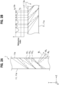
- the AR optical element 1 includes a periodic structure 10 of refractive index having an optical normal B in a direction different from a physical normal A.
- the AR optical element 1 includes the periodic structure 10 of refractive index having the normal B in the different direction from the normal A of the surface 11 of the micro-region that reflects the group of incident rays.
- the periodic structure 10 of the refractive index is configured at an interval V so that the refractive index distribution varies periodically in directions along the Y-axis (the same applies to directions along the X-axis).
- the periodic structure 10 of the refractive index has a refractive index becoming higher and lower in a range of a maximum refractive index modulation amount ⁇ n with respect to a referential average refractive index no at both ends of the interval V.
- FIG. 1B is an example of a higher refractive index, but the refractive index may be set as low as (n O - ⁇ n).
- the periodic structure 10 of the refractive index is inclined with respect to a normal A of a surface 11 of the micro-region.
- the periodic structure 10 of the refractive index is configured to be continuous from a surface 11a of one micro-region to a surface 11b of the other micro-region.
- the AR optical element 1 differs from a dielectric multilayer film, which is fabricated by vapor deposition and has a periodic structure having a normal in the same directions as the physical normal.
- the AR optical element 1 has the periodic structure 10 of refractive indexes shown in FIG. 1A multiplexed.
- the periodic structures 10 of refractive indexes with normal B having different directions are formed in a manner of overlapping on the same region along the Y-axis.
- the first periodic structure of the refractive index 10, is illustrated with dashed lines, and a normal of the periodic structure of refractive index 10 1 is indicated by B 1 .
- the periodic structure of the second refractive index 10z is illustrated with solid lines, and a normal of the periodic structure of refractive index 10 2 is indicated by B 2 .
- the periodic structure of the third refractive index 10 3 is illustrated with a long dashed line, and a normal of the periodic structure of refractive index 10 3 is indicated by B 3 .
- the AR optical element 1 is configured to have three periodic structure of refractive index 10i to 10 3 multiplexed within a range of the maximum refractive index modulation amount ⁇ n with respect to the referential average refractive index n O .
- the AR optical element 1 is able to reflect light rays with an uniform intensity distribution over a predetermined angular width by multiplexing the periodic structures of refractive indexes 10.
- multiplexing of the periodic structures of refractive indexes 10 means to form the periodic structures of the refractive index 10 having the normal B different in their directions at the same place.
- the normal ⁇ normal of the periodic structure of refractive index 10 is expressed by the following equation (1).
- ⁇ IN is an incident vector indicating directions of a group of incident light rays
- ⁇ OUT is an emission vector of a central ray of a group of multiple emitted rays directing toward a central position U of an observation area.
- ⁇ IN and ⁇ OUT are actually angles at the AR optical element 1 having the average refractive index no that is converted from angles in the air [Math. 1]
- ⁇ normal ⁇ IN + ⁇ OUT / 2 ⁇ 90 °
- the normal ⁇ normal , the incident vector ⁇ IN , and the output vector ⁇ OUT are all referenced to the Z-axis (normal A) and are positive counterclockwise with respect to the X-axis.
- the normal ⁇ normal of the periodic structure of the refractive index 10 varies according to the incident vector ⁇ IN and the output vector ⁇ OUT at each point 12,
- the interval V between the periodic structures 10 of the refractive indexes is expressed by the following equation (2).
- the recording and reproducing wavelength ⁇ of the AR optical element 1 represents a wavelength of light incident onto the AR optical element 1 during reproduction.
- V ⁇ / n O / 2 sin ⁇ IN ⁇ ⁇ OUT / 2
- the periodic structure of refractive index 10 are multiplexed by the angular interval ⁇ Y .
- the angular interval ⁇ Y equals a vertical spread angle of the group of incident light rays.
- the group of outgoing light rays achieves almost uniform intensity distribution within an angular width ⁇ Y (the same in a horizontal angle width ⁇ X ).
- the multiplicity K and L of the periodic structures of the refractive index 10 in the horizontal and vertical directions shall be expressed by the following equations (3) and (4).
- the final multiplicity M which is obtained by summing the periodic structures of the refractive index 10 in the horizontal and vertical directions, is expressed by the following equation (5) (where the floor(x) is a function that returns an integer maximum value less than or equal to x).
- K floor ⁇ X / ⁇ X + 1
- L floor ⁇ Y / ⁇ Y + 1
- M KL
- phases of the periodic structures of refractive indexes 10 should be matched at adjacent points 12.
- FIG. 2 only one point 12 located in a center of the AR optical element 1 is illustrated, but actually, parameters are calculated at all points 12 of the AR optical element 1.
- the AR optical element 1 has a refractive index distribution achieved by a multiplexed periodic structure of refractive index10. Therefore, in order to manufacture the AR optical element 1 using the conventional manufacturing method that makes object light and reference light interfere with each other, it is necessary to optically superimpose multiple object light rays incident at a precise angular interval ⁇ and to control incident angles of each object light and a reference light depending on recording positions, but it is difficult to construct such an interference system to manufacture the AR optical elements 1.
- a hologram printing technology which optically reproduces wavefront designed by a computer- generated hologram and exposes the wavefront as object light, makes it easy to manufacture the AR optical element 1.
- the computer-generated hologram is a technology that uses a computer to generate interference fringes (hologram data) between an object light and a reference light so as to obtain a desired reproduced image.
- the step S1 uses the equations (1) through (5) to calculate the normal ⁇ normal , the interval V, and the multiplicities K, L, and M.
- the step S2 performs computation of the computer-generated hologram so that the periodic structure of refractive index 10 having the normal ⁇ normal are multiplexed with the interval V and the multiplicity M.
- the step S2 uses the computer-generated hologram to generate the hologram data that reproduces object light capable of generating the AR optical element 1.
- the step S3 produces the AR optical element 1 by hologram printing technology based on a result of the computation of the computer-generated hologram.
- the step S3 uses a hologram printer to make the wavefront as object light, which is reproduced by the hologram data generated in the step S2, interfere with a reference light and to expose the wavefront onto a general hologram recording material (for example, photosensitive photopolymer).
- a general hologram recording material for example, photosensitive photopolymer.
- the AR optical element 1 that has so high image quality, high efficiency of light utilization, and small size that is able to be used in a 3D AR display device.
- the AR optical element 1 is able to reflect the group of light rays incident from the projection device 3 in a desired directions with appropriate angular widths, angular intervals, and number of rays, and to focus a group of light rays with a uniform intensity distribution on a desired observation area, and thereby suppressing uneven luminance and improving image quality and efficiency of light utilization.
- the AR optical element 1 compared to the first and second conventional technologies, is able to reflect only incident light having desired wavelength and transmit remaining incident light having other wavelengths according to the Bragg condition, and therefore, is able to achieve both high-luminance image display and high transmittance of background light.
- FIG. 5 a configuration of an AR optical element 1B according to the second embodiment is explained in terms of differences from the first embodiment.
- this second embodiment differs from the first embodiment in that the AR optical element 1B is a transmission type that transmits incident light from the projection device.
- the AR optical element 1B has periodic structures of refractive indexes multiplexed at a predetermined interval and a multiplicity, the periodic structure having optical normal in different direction from a physical normal of a plane of a micro-region that transmits a group of light rays.
- the AR optical element 1B has a multiplexed periodic structure of refractive index having optical normal in different directions with respect to the physical normal of the surface of the micro-region through which the group of incident rays is transmitted, at a predetermined interval and multiplexing number ( Figure 1 ).
- the AR optical element 1B has a multiplexed periodic structures of refractive indexes as in the first embodiment, and the method of calculating parameters is the same as the first embodiment.
- the normal of the periodic structure of the refractive index ⁇ normal is expressed by the aforementioned equation (1), as in the first embodiment.
- the normal ⁇ normal , the incident vector ⁇ IN , and the output vector ⁇ OUT are all referenced to the Z-axis (normal A) and are positive counterclockwise to the X-axis.
- the normal of the periodic structure of the refractive index, ⁇ normal varies depending on the incident vector ⁇ IN and the output vector ⁇ OUT at each point 12B.
- the interval V of the periodic structures of refractive indexes is expressed by the aforementioned equation (2) as in the first embodiment.
- the multiplicities K, L, and M of the periodic structure of refractive index are expressed respectively by the above equations (3) to (5), as in the first embodiment.
- the phases of the periodic structure of refractive index should preferably match each other between adjacent points 12B.
- FIG. 5 illustrates only one point 12B located in a center of the AR optical element 1B, but actually, the parameters are calculated at all points 12B of the AR optical element 1B.
- the AR optical element 1B is able to transmit a group of light rays incident from the projection device 3 in desired directions with appropriate angular width, angular interval, and number of rays, and to focus the group of light rays with uniform intensity distribution on a desired observation area, and thus to improve image quality and light utilization efficiency.
- An AR display device 2 uses the light field technique to perform an AR display of a stereoscopic image (image that is viewed three-dimensionally as if it has a three-dimensional shape) or an image with directionality (image whose given information changes depending on an observation direction).
- the AR display device 2 is equipped with a reflective type of AR optical element 1 (see FIG. 3 ) and N projection devices 3 (note that N is larger or equal to 2). Because the AR optical element 1 is the same as in the first embodiment, its description is omitted (see FIGS. 1 to 3 ).
- the projection device 3 is a well-known projector that projects elemental images to make the AR optical element 1 display stereoscopic or directional images as a group of light rays.
- FIG. 6 shows only the incident vector ⁇ IN and the output vector ⁇ OUT at a center and both ends of the AR optical element 1, but actually, there exist the incident vector ⁇ IN and the output vector ⁇ OUT at every points of the AR optical element 1.
- the incident vector ⁇ IN indicates a direction (incidence angle) of the group of light rays incident from the projection device 3 located at a center.
- the outgoing vector ⁇ OUT indicates a direction toward a center position U of the observation area.
- the projection device 3 located at a center is defined as a reference similarly to the horizontal directions, and a calculation of the angle width ⁇ Y etc. is the same as in the first embodiment, and therefore explanation thereof is omitted.
- the horizontal and vertical center positions U of the observation area may be set independently of each other.
- the AR display device 2 allows displaying on the AR display element 1 used as a screen stereoscopic or directional images with the light field technique that reproduces a large number of light rays without gaps in the horizontal directions.
- the AR display device 2 like the first embodiment, achieves both high luminance video display and high transmittance of background light.
- the AR optical element 1 reflects a group of incident light rays in a desired reflection direction at an appropriate angular interval, angular width, and number of rays
- the AR display device 2 prevents crosstalk among multiple projection devices 3 as the crosstalk in the second conventional technology, and thereby allows improvement in image quality and efficiency of light utilization.
- the AR display device 2 allows AR display of stereoscopic images and directional images with the light field technique using a single AR optical element 1.
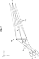
- FIG. 7 a configuration of the AR display device 2B according to the fourth embodiment is explained in terms of the differences from the third embodiment.
- the third embodiment is explained that the AR display device 2 is equipped with the reflective type of AR optical element 1.
- the fourth embodiment differs from the third embodiment in that the AR display device 2B is equipped with a transmission type of AR optical element 1B.
- the AR display device 2B is equipped with a transmission type of AR optical element 1B ( FIGS. 5A and 5B ) and N projection devices 3.
- N the projection devices 3
- three of the projection devices 3 are arranged horizontally in arc shapes or straight lines with an angular interval ⁇ p, and horizontal and vertical spread angles of the light rays incident from each projection device 3 are respectively ⁇ X and ⁇ Y .
- FIG. 7 shows only the incidence vector ⁇ IN and the output vector ⁇ OUT located at both ends of the AR optical element 1B, but actually, the incident vector ⁇ IN and the output vector ⁇ OUT exists at all points of the AR optical element 1B.
- the AR optical element 1B in the horizontal directions, can be manufactured with setting of the angle width ⁇ X in the equation (3) as ⁇ p .
- the incident vector ⁇ IN indicates a direction (incidence angle) of a group of light rays incident from the projection device 3 located at a center.
- the outgoing vector ⁇ OUT indicates a direction toward a center position U of the observation area.
- the projection device 3 located at a center is defined as a reference similarly to the horizontal directions, and therefore explanation is omitted.
- the horizontal and vertical center positions U of the observation area may be set independently of each other.
- the AR display device 2B allows displaying on the AR display element 1B used as a screen stereoscopic or directional images with the light field technique that reproduces a large number of light rays without gaps in the horizontal directions.
- the AR display device 2B of the fourth embodiment achieves both a high luminance video display and a high transmittance of background light.
- the AR optical element 1B transmits the group of incident light rays in a desired reflection direction at an appropriate angular interval, angular width, and number of rays, which prevents crosstalk from occurring between multiple projection devices 3 as the crosstalk in the second conventional technology, resulting improvement of image quality and efficiency of light utilization.
- the AR display device 2B allows AR display of stereoscopic images and directional images with the light field technique using a single AR optical element 1B.
- the AR display device 2C performs two-dimensional AR display and includes a reflective type of AR optical element ( FIG. 3 ) and one projection device 3.
- the AR display device 2C forms an image from the projection device 3 onto the AR optical element 1.
- the incident vector ⁇ IN indicates a direction (incidence angle) of a group of light rays incident from the projection device 3.
- the output vector ⁇ OUT indicates a direction to a center position U of the observation area, which center is a center of the user's observation location.
- FIG. 8 shows the incidence vector ⁇ IN and the output vector ⁇ OUT at two points located at both ends of the AR optical element 1, but that actually, the incident vector ⁇ IN and the output vector ⁇ OUT exist at every points of the AR optical element 1.
- the AR display device 2C uses the AR optical element 1 and therefore improves the efficiency of light utilization. Furthermore, the AR display device 2C, compared to the first conventional technology, allows improving uneven luminance within a range of a width W X and W Y of the observation area, the higher efficiency of light utilization, and compatibility of high luminance video display and high transmittance of background light.
- the AR display device 2C is described to be equipped with the reflective type of AR optical element 1.
- the sixth embodiment differs from the fifth embodiment in that the AR display device 2D is equipped with a transmission type of AR optical element 1B.
- the AR display device 2D performs a two-dimensional AR display and is equipped with the transmission type of AR optical element 1B ( FIG. 5 ) and one projection device 3.
- the AR display device 2D forms an image from one projection device 3 onto the AR optical element 1B.
- FIG. 9 shows the incidence vector ⁇ IN and the output vector ⁇ OUT at two points located at both ends of the AR optical element 1B, but that the incident vector ⁇ IN and the output vector ⁇ OUT actually exist at every points of the AR optical element 1B.
- the AR display device 2D employs the AR optical element 1B, which improves the efficiency of light utilization. Furthermore, the AR display device 2D, compared to the first conventional technology, improves the uneven luminance within a range of width W X and W Y of an observation area, and allows higher efficiency of light utilization and compatibility of high luminance video display and high transmittance of the background light.
- the AR optical element is not limited to that having a flat shape.
- the AR optical elements of the present invention can be used, for example, for smart glasses and an in-vehicle head-up display, which are in high demand for AR applications. Further, the AR optical elements can also be applied for a digital signage that displays stereoscopic images, multilingual displays and directional displays that require different image displays and different information presentations for respective direction. Furthermore, the AR optical elements of the present invention can be used for security displays incorporated in ATMs and other devices that need to display specific images only to specific users.
Landscapes
- Physics & Mathematics (AREA)
- General Physics & Mathematics (AREA)
- Optics & Photonics (AREA)
- Holo Graphy (AREA)
- Projection Apparatus (AREA)
Applications Claiming Priority (2)
| Application Number | Priority Date | Filing Date | Title |
|---|---|---|---|
| JP2020158276A JP7466903B2 (ja) | 2020-09-23 | 2020-09-23 | Ar表示装置用光学素子及びその製造方法、並びに、ar表示装置 |
| PCT/JP2021/034066 WO2022065185A1 (fr) | 2020-09-23 | 2021-09-16 | Élément optique à réalité augmentée, procédé de fabrication de celui-ci et dispositif d'affichage à réalité augmentée |
Publications (2)
| Publication Number | Publication Date |
|---|---|
| EP4220251A1 true EP4220251A1 (fr) | 2023-08-02 |
| EP4220251A4 EP4220251A4 (fr) | 2024-10-09 |
Family
ID=80846628
Family Applications (1)
| Application Number | Title | Priority Date | Filing Date |
|---|---|---|---|
| EP21872315.3A Pending EP4220251A4 (fr) | 2020-09-23 | 2021-09-16 | Élément optique à réalité augmentée, procédé de fabrication de celui-ci et dispositif d'affichage à réalité augmentée |
Country Status (5)
| Country | Link |
|---|---|
| US (1) | US12498513B2 (fr) |
| EP (1) | EP4220251A4 (fr) |
| JP (1) | JP7466903B2 (fr) |
| CN (1) | CN116057453A (fr) |
| WO (1) | WO2022065185A1 (fr) |
Families Citing this family (1)
| Publication number | Priority date | Publication date | Assignee | Title |
|---|---|---|---|---|
| JP7485713B2 (ja) | 2022-03-28 | 2024-05-16 | カヤバ株式会社 | 3価クロムめっき部品の製造方法 |
Family Cites Families (19)
| Publication number | Priority date | Publication date | Assignee | Title |
|---|---|---|---|---|
| US3674336A (en) * | 1970-08-28 | 1972-07-04 | Bell Telephone Labor Inc | Light wave coupling into thin film light guides with bragg type gratings |
| US5016953A (en) * | 1989-08-31 | 1991-05-21 | Hughes Aircraft Company | Reduction of noise in computer generated holograms |
| US5886675A (en) | 1995-07-05 | 1999-03-23 | Physical Optics Corporation | Autostereoscopic display system with fan-out multiplexer |
| JP4242974B2 (ja) | 1999-08-10 | 2009-03-25 | 日本分光株式会社 | ホログラフィックノッチフィルタ製造方法 |
| JP2002116442A (ja) | 2000-10-06 | 2002-04-19 | Sharp Corp | 液晶表示装置、液晶表示装置の製造方法、および液晶表示装置の製造装置 |
| JP2002258215A (ja) | 2001-03-06 | 2002-09-11 | Telecommunication Advancement Organization Of Japan | 立体映像表示装置 |
| JP4751532B2 (ja) | 2001-07-03 | 2011-08-17 | 大日本印刷株式会社 | 光学系及びそれを用いた装置 |
| US7092133B2 (en) * | 2003-03-10 | 2006-08-15 | Inphase Technologies, Inc. | Polytopic multiplex holography |
| JP2004347784A (ja) * | 2003-05-21 | 2004-12-09 | Sharp Corp | 反射型光学素子 |
| US7418170B2 (en) * | 2004-03-29 | 2008-08-26 | Sony Corporation | Optical device and virtual image display device |
| JP4655771B2 (ja) * | 2005-06-17 | 2011-03-23 | ソニー株式会社 | 光学装置及び虚像表示装置 |
| JP4999485B2 (ja) * | 2007-02-08 | 2012-08-15 | 株式会社リコー | 光束分割素子および光束分割方法 |
| JP4518193B2 (ja) | 2008-06-10 | 2010-08-04 | ソニー株式会社 | 光学装置および虚像表示装置 |
| CN104777535B (zh) * | 2015-03-25 | 2017-05-24 | 东南大学 | 一种复用体全息光栅 |
| WO2017073157A1 (fr) * | 2015-10-28 | 2017-05-04 | ソニー株式会社 | Dispositif optique, dispositif d'affichage et procédé de fabrication d'élément électroluminescent |
| AU2017247104B2 (en) * | 2016-04-04 | 2019-12-12 | Akonia Holographics, Llc. | Pupil equalization |
| US11467407B2 (en) * | 2017-09-26 | 2022-10-11 | Apple Inc. | Displays with volume phase gratings |
| GB2574884A (en) | 2018-06-22 | 2019-12-25 | Metamaterial Tech Inc | Spatially varying volume holographic gratings |
| JP7119862B2 (ja) | 2018-10-01 | 2022-08-17 | 株式会社デンソー | 虚像表示装置 |
-
2020
- 2020-09-23 JP JP2020158276A patent/JP7466903B2/ja active Active
-
2021
- 2021-09-16 US US18/245,477 patent/US12498513B2/en active Active
- 2021-09-16 CN CN202180054019.2A patent/CN116057453A/zh active Pending
- 2021-09-16 WO PCT/JP2021/034066 patent/WO2022065185A1/fr not_active Ceased
- 2021-09-16 EP EP21872315.3A patent/EP4220251A4/fr active Pending
Also Published As
| Publication number | Publication date |
|---|---|
| CN116057453A (zh) | 2023-05-02 |
| WO2022065185A1 (fr) | 2022-03-31 |
| US12498513B2 (en) | 2025-12-16 |
| JP2022052092A (ja) | 2022-04-04 |
| US20230333300A1 (en) | 2023-10-19 |
| JP7466903B2 (ja) | 2024-04-15 |
| EP4220251A4 (fr) | 2024-10-09 |
Similar Documents
| Publication | Publication Date | Title |
|---|---|---|
| US11789268B2 (en) | Optical expander device | |
| US10845525B2 (en) | Imaging light guide with grating-expanded light distribution | |
| EP2153266B1 (fr) | Expanseur de faisceau diffractif et afficheur virtuel basé sur un expanseur de faisceau diffractif | |
| JP7627756B2 (ja) | 区分けされた回折光学要素を備えた画像光ガイド | |
| CN112711138B (zh) | 具有宽的观看窗口的显示设备 | |
| WO2021252672A1 (fr) | Guide de lumière d'image avec optique diffractive zonée | |
| US20240094456A1 (en) | Image light guide with compound in-coupling diffractive optic | |
| EP3417344B1 (fr) | Affichage tridimensionnel complet dynamique | |
| US12235453B2 (en) | Display apparatus for providing expanded viewing window | |
| CN116171401A (zh) | 具有复合衍射光学元件的图像光导和由其制成的头戴式显示器 | |
| US20020101657A1 (en) | Stereoscopic display device | |
| EP4220251A1 (fr) | Élément optique à réalité augmentée, procédé de fabrication de celui-ci et dispositif d'affichage à réalité augmentée | |
| US20250334809A1 (en) | Dual index waveguide stack | |
| JP7567813B2 (ja) | 画像表示装置 | |
| US20240061247A1 (en) | Display device | |
| JP2025510847A (ja) | 複数の波長範囲画像光ガイドシステム | |
| HK40111961A (zh) | 多波长范围成像光导系统 | |
| HK40098221A (zh) | 具有分区衍射光学器件的图像光导 | |
| HK40087566A (zh) | 具有分区衍射光学器件的图像光导 | |
| HK40100783A (zh) | 具有复合耦入衍射光学件的图像光导 | |
| CN116547574A (zh) | 具有分区衍射光学器件的图像光导 |
Legal Events
| Date | Code | Title | Description |
|---|---|---|---|
| STAA | Information on the status of an ep patent application or granted ep patent |
Free format text: STATUS: THE INTERNATIONAL PUBLICATION HAS BEEN MADE |
|
| PUAI | Public reference made under article 153(3) epc to a published international application that has entered the european phase |
Free format text: ORIGINAL CODE: 0009012 |
|
| STAA | Information on the status of an ep patent application or granted ep patent |
Free format text: STATUS: REQUEST FOR EXAMINATION WAS MADE |
|
| 17P | Request for examination filed |
Effective date: 20230316 |
|
| AK | Designated contracting states |
Kind code of ref document: A1 Designated state(s): AL AT BE BG CH CY CZ DE DK EE ES FI FR GB GR HR HU IE IS IT LI LT LU LV MC MK MT NL NO PL PT RO RS SE SI SK SM TR |
|
| DAV | Request for validation of the european patent (deleted) | ||
| DAX | Request for extension of the european patent (deleted) | ||
| A4 | Supplementary search report drawn up and despatched |
Effective date: 20240911 |
|
| RIC1 | Information provided on ipc code assigned before grant |
Ipc: G03H 1/26 20060101ALI20240905BHEP Ipc: G03H 1/08 20060101ALI20240905BHEP Ipc: G03H 1/04 20060101ALI20240905BHEP Ipc: G02B 27/01 20060101ALI20240905BHEP Ipc: G02B 27/02 20060101ALI20240905BHEP Ipc: G02B 5/32 20060101AFI20240905BHEP |
|
| GRAP | Despatch of communication of intention to grant a patent |
Free format text: ORIGINAL CODE: EPIDOSNIGR1 |
|
| STAA | Information on the status of an ep patent application or granted ep patent |
Free format text: STATUS: GRANT OF PATENT IS INTENDED |
|
| INTG | Intention to grant announced |
Effective date: 20260216 |