EP4220320B1 - Dispositif de traitement d'informations, procédé de traitement d'informations et programme - Google Patents
Dispositif de traitement d'informations, procédé de traitement d'informations et programme Download PDFInfo
- Publication number
- EP4220320B1 EP4220320B1 EP21872438.3A EP21872438A EP4220320B1 EP 4220320 B1 EP4220320 B1 EP 4220320B1 EP 21872438 A EP21872438 A EP 21872438A EP 4220320 B1 EP4220320 B1 EP 4220320B1
- Authority
- EP
- European Patent Office
- Prior art keywords
- value
- component
- information processing
- anomaly
- learned model
- Prior art date
- Legal status (The legal status is an assumption and is not a legal conclusion. Google has not performed a legal analysis and makes no representation as to the accuracy of the status listed.)
- Active
Links
Images


Classifications
-
- G—PHYSICS
- G05—CONTROLLING; REGULATING
- G05B—CONTROL OR REGULATING SYSTEMS IN GENERAL; FUNCTIONAL ELEMENTS OF SUCH SYSTEMS; MONITORING OR TESTING ARRANGEMENTS FOR SUCH SYSTEMS OR ELEMENTS
- G05B23/00—Testing or monitoring of control systems or parts thereof
- G05B23/02—Electric testing or monitoring
- G05B23/0205—Electric testing or monitoring by means of a monitoring system capable of detecting and responding to faults
- G05B23/0218—Electric testing or monitoring by means of a monitoring system capable of detecting and responding to faults characterised by the fault detection method dealing with either existing or incipient faults
- G05B23/0224—Process history based detection method, e.g. whereby history implies the availability of large amounts of data
- G05B23/024—Quantitative history assessment, e.g. mathematical relationships between available data; Functions therefor; Principal component analysis [PCA]; Partial least square [PLS]; Statistical classifiers, e.g. Bayesian networks, linear regression or correlation analysis; Neural networks
-
- G—PHYSICS
- G05—CONTROLLING; REGULATING
- G05B—CONTROL OR REGULATING SYSTEMS IN GENERAL; FUNCTIONAL ELEMENTS OF SUCH SYSTEMS; MONITORING OR TESTING ARRANGEMENTS FOR SUCH SYSTEMS OR ELEMENTS
- G05B23/00—Testing or monitoring of control systems or parts thereof
- G05B23/02—Electric testing or monitoring
- G05B23/0205—Electric testing or monitoring by means of a monitoring system capable of detecting and responding to faults
- G05B23/0218—Electric testing or monitoring by means of a monitoring system capable of detecting and responding to faults characterised by the fault detection method dealing with either existing or incipient faults
- G05B23/0224—Process history based detection method, e.g. whereby history implies the availability of large amounts of data
- G05B23/0227—Qualitative history assessment, whereby the type of data acted upon, e.g. waveforms, images or patterns, is not relevant, e.g. rule based assessment; if-then decisions
-
- F—MECHANICAL ENGINEERING; LIGHTING; HEATING; WEAPONS; BLASTING
- F24—HEATING; RANGES; VENTILATING
- F24F—AIR-CONDITIONING; AIR-HUMIDIFICATION; VENTILATION; USE OF AIR CURRENTS FOR SCREENING
- F24F11/00—Control or safety arrangements
- F24F11/30—Control or safety arrangements for purposes related to the operation of the system, e.g. for safety or monitoring
- F24F11/32—Responding to malfunctions or emergencies
- F24F11/38—Failure diagnosis
-
- G—PHYSICS
- G05—CONTROLLING; REGULATING
- G05B—CONTROL OR REGULATING SYSTEMS IN GENERAL; FUNCTIONAL ELEMENTS OF SUCH SYSTEMS; MONITORING OR TESTING ARRANGEMENTS FOR SUCH SYSTEMS OR ELEMENTS
- G05B23/00—Testing or monitoring of control systems or parts thereof
- G05B23/02—Electric testing or monitoring
- G05B23/0205—Electric testing or monitoring by means of a monitoring system capable of detecting and responding to faults
- G05B23/0208—Electric testing or monitoring by means of a monitoring system capable of detecting and responding to faults characterized by the configuration of the monitoring system
- G05B23/021—Electric testing or monitoring by means of a monitoring system capable of detecting and responding to faults characterized by the configuration of the monitoring system adopting a different treatment of each operating region or a different mode of the monitored system, e.g. transient modes; different operating configurations of monitored system
-
- G—PHYSICS
- G06—COMPUTING OR CALCULATING; COUNTING
- G06N—COMPUTING ARRANGEMENTS BASED ON SPECIFIC COMPUTATIONAL MODELS
- G06N20/00—Machine learning
-
- G—PHYSICS
- G06—COMPUTING OR CALCULATING; COUNTING
- G06N—COMPUTING ARRANGEMENTS BASED ON SPECIFIC COMPUTATIONAL MODELS
- G06N5/00—Computing arrangements using knowledge-based models
- G06N5/04—Inference or reasoning models
Definitions
- the present disclosure relates to an information processing apparatus, an information processing method, and a program.
- US 2019/101305 A1 and US 2019/101892 A1 disclose systems and methods for determining whether a learned model needs to be generated or not.
- Patent Document 1 Japanese Unexamined Patent Application Publication No. 2018-146448
- the purpose of the present disclosure is to provide a technology that enables appropriate determination of anomaly of a device.
- anomaly determination of the device can be appropriately performed.
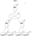
- FIG. 1 illustrates an example of the system configuration of the information processing system 1 according to the embodiment.
- the information processing system 1 includes an information processing apparatus 10A, an information processing apparatus 10B, and an information processing apparatus 10C (hereafter, when it is not necessary to distinguish each of these from each other, simply referred to as "the information processing apparatus 10").
- the information processing system 1 also includes a device 20A, a device 20B, a device 20C, and a device 20D (hereafter, when it is not necessary to distinguish each of these from each other, simply referred to as the "device 20").
- the numbers of the information processing apparatuses 10 and the devices 20 are not limited to the example in FIG. 1 .
- the information processing apparatus 10 and the device 20 may be connected so as to be able to communicate via, for example, a network NW such as the Internet, a wireless LAN (Local Area Network), a LAN, a mobile phone network such as LTE (Long Term Evolution) and 5G, a signal line, or the like.
- the device 20 may be installed in, for example, a residence, an office, a public facility, or the like.
- the information processing apparatus 10 may be, for example, a server on a cloud. Further, the information processing apparatus 10 may be, for example, an edge server installed in a building where multiple devices 20 are installed. Further, the information processing apparatus 10 may be housed in, for example, the device 20 (for example, the indoor housing of an air conditioner).
- the information processing apparatus 10A, the information processing apparatus 10B and the information processing apparatus 10C may be the same apparatus.
- the device 20 may be, for example, a variety of devices such as air conditioners, refrigerators, water heaters, lighting, and the like, and may have an Internet of Things (IoT) device that transmits various kinds of measured information to the information processing apparatus 10.
- IoT Internet of Things
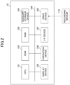
- FIG. 2 illustrates an example of the hardware configuration of the information processing apparatus 10 according to the embodiment.
- the information processing apparatus 10 includes a CPU (Central Processing Unit) 101, a ROM (Read Only Memory) 102, and a RAM (Random Access Memory) 103.
- the CPU 101, the ROM 102, and the RAM 103 form what is referred to as a computer.
- the information processing apparatus 10 includes an auxiliary storage device 104, a display device 105, an operation device 106, an I/F (Interface) device 107, and a drive device 108.
- the pieces of hardware of the information processing apparatus 10 are connected to each other via a bus 109.
- the CPU 101 is an arithmetic device that executes various programs (e.g., machine learning programs, etc.) installed in the auxiliary storage device 104.
- the ROM 102 is a non-volatile memory.
- the ROM 102 functions as a main storage device and stores various programs, data, etc., necessary for the CPU 101 to execute various programs installed in the auxiliary storage device 104.
- the ROM 102 stores boot programs, such as BIOS (Basic Input/Output System) and EFI (Extensible Firmware Interface).
- the RAM 103 is a volatile memory, such as DRAM (Dynamic Random Access Memory) and SRAM (Static Random Access Memory).
- the RAM 103 functions as a main storage device and provides a work area that is expanded when various programs installed in the auxiliary storage device 104 are executed by the CPU 101.
- the auxiliary storage device 104 stores various programs and information used when various programs are executed.
- the display device 105 is a display device for displaying various kinds of information.
- the operation device 106 is an operation device for receiving various operations.
- the I/F device 107 is a communication device that communicates with external devices.
- the drive device 108 is a device for setting the recording medium 110.
- the recording medium 110 here includes media for recording information optically, electrically or magnetically, such as a CD-ROM, a flexible disk, a magneto-optical disk, etc. Further, the recording medium 110 may include a semiconductor memory, etc., for electrically recording information, such as ROM, flash memory, etc.
- auxiliary storage device 104 Various programs installed in the auxiliary storage device 104 are installed, for example, when the distributed recording medium 110 is set in the drive device 108 and various programs recorded in the recording medium 110 are read by the drive device 108.
- various programs installed in the auxiliary storage device 104 may be installed by being downloaded from a network (not illustrated).
- the configuration of the device 20 according to the embodiment will be described.
- An example in which the device 20 is an air conditioner will be described below.
- FIG. 3A illustrates an example of the configuration of an outdoor unit 2000 of the device 20 according to the embodiment.
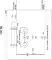
- FIG. 3B illustrates an example of the configuration of an indoor unit 2500 of the device 20 according to the embodiment.
- the control device 40 may be built into, for example, the outdoor unit 2000 or the indoor unit 2500 of the device 20.
- the control device 40 of the device 20 may be implemented by a microcontroller in which the CPU, a memory, and an input/output unit are built into one integrated circuit. Further, the control device 40 of the device 20 may be implemented by a circuit such as an ASIC (Application Specific Integrated Circuit), a DSP (digital signal processor), an FPGA (field programmable gate array), or the like. Further, the control device 40 of the device 20 may be implemented by the computer illustrated in FIG. 2 above.
- the device 20 is equipped with various devices configuring a refrigerant circuit and various sensors. Each device configuring the refrigerant circuit is controlled by the control device 40.
- the refrigerant circuit is, for example, a closed circuit filled with a refrigerant such as chlorofluorocarbon.
- the refrigerant circuit may be configured, for example, such that the refrigerant circulates to perform a vapor compression type refrigeration cycle.
- the outdoor unit 2000 of the device 20 includes a compressor 201, an outdoor heat exchanger 202, an electronic expansion valve 203, an electronic expansion valve 204, an electromagnetic valve 205 (oil separator oil return), an electromagnetic valve 206 (oil separator bypass), an electromagnetic valve 207 (accumulator oil return), a four-way switching valve 208, a high-pressure sensor 209, a low-pressure sensor 210, a high-pressure switch 211, a pressure adjustment valve 212, a supercooling heat exchanger 213, a capillary tube 214, a thermistor 215, a thermistor 216, a thermistor 217, a thermistor 218, a thermistor 219, a thermistor 220, a thermistor 221, a thermistor 222, a refrigerant cooling plate 223, etc.
- the compressor 201 compresses and discharges the taken in refrigerant. For example, by changing the rotational speed of the motor (rotational speed of the compressor 201) by changing the frequency of the alternating current supplied from the inverter of the compressor 201 to the motor (not illustrated), the capacity of the compressor 201 can be changed.
- the rotational speed may be, for example, the number of rotations per unit time.
- the outdoor heat exchanger 202 air heat exchanger
- the outdoor air taken in by the outdoor fan and the refrigerant exchange heat.
- the opening (hole size) of the electronic expansion valve 203 (main) and the electronic expansion valve 204 (injection) is adjusted, for example, by the valve element being driven by a pulse motor.
- the electronic expansion valve 203 is controlled so that the outlet overheat of the outdoor heat exchanger becomes constant during a heating operation.
- the electronic expansion valve 204 is controlled so that the outlet overheat of the supercooling heat exchanger 213 becomes constant.
- the electromagnetic valve 205 oil separator oil return
- the electromagnetic valve 206 oil separator bypass
- the electromagnetic valve 207 accumulator oil return
- the four-way switching valve 208 switches between cooling and heating operations.
- the high pressure sensor 209 is a sensor that detects high pressure.
- the high pressure is the high pressure in the refrigeration cycle of the device 20 (hereafter, also referred to simply as "high pressure" as appropriate), and may be, for example, the pressure of the refrigerant compressed and discharged by the compressor 201 (the discharge pressure of the compressor 201) or the pressure of the refrigerant in a condenser.
- the low pressure sensor 210 is a sensor that detects low pressure.
- the low pressure is the low pressure in the refrigeration cycle of the device 20 (hereafter, also referred to simply as "low pressure" as appropriate), and may be, for example, the pressure of the refrigerant taken into the compressor 201 (the pressure of the refrigerant before being compressed into the compressor 201).
- the high pressure switch 211 stops the operation of the device 20 when the pressure is above a predetermined pressure in order to avoid the increase of the high pressure when the compressor 201 has an anomaly.
- the pressure adjustment valve 212 opens the liquid tube when the pressure is above the predetermined pressure to avoid the increase of the high pressure in order to prevent the breakage of the functional components due to the increase of the pressure during transportation and storage.
- the supercooling heat exchanger 213 supercools the liquid refrigerant.
- the capillary tube 214 returns the refrigerating machine oil separated by the oil separator 224 to the compressor 201.
- the thermistor 215 is a sensor (temperature sensor) that detects (measures) the outside air temperature.
- the outside air temperature measured by the thermistor 215 may be used, for example, to correct the discharge tube temperature.
- the thermistor 216 is a sensor that detects the discharge tube temperature indicating the temperature of the refrigerant discharged from the compressor 201.
- the discharge tube temperature measured by the thermistor 216 may be used, for example, for temperature protection control, etc., of the compressor 201.
- the thermistor 217 is a sensor for detecting the gas tube temperature at the inlet of the accumulator 225.
- the gas tube temperature measured by the thermistor 217 may be used, for example, for control to keep the intake superheating level constant during heating.
- the thermistor 218 is a sensor for detecting the liquid tube temperature of the outdoor heat exchanger 202.
- the liquid tube temperature measured by the thermistor 218 may be used, for example, for overfill determination, etc., during test operation.
- the thermistor 219 is a sensor for detecting the liquid tube temperature of the supercooling heat exchanger 213.
- the thermistor 220 is a sensor for detecting the evaporation-side gas tube temperature of the supercooling heat exchanger 213.
- the evaporation-side gas tube temperature measured by the thermistor 219 may be used, for example, to control the overheat at the outlet of the supercooling heat exchanger 213 to a constant value, etc.
- the thermistor 221 is a sensor that detects the liquid tube temperature of the outdoor heat exchanger 202.
- the liquid tube temperature measured by the thermistor 221 may be used, for example, to determine a defrost operation.
- the thermistor 222 is a sensor that detects the surface temperature of the compressor 201.
- the control device 40 may stop the operation of the device 20 when the surface temperature exceeds the threshold value in order to avoid the temperature of the compressor 201 rising in the event of an anomaly.
- the thermistor 226 is a sensor that detects the inlet tube temperature indicating the temperature of the refrigerant taken into the compressor 201.
- the refrigerant cooling plate 223 is a cooling plate for cooling the refrigerant liquid.
- the accumulator 225 is, for example, a device that separates the liquid and gas of the refrigerant taken into the compressor 201, and allows only the gas to be taken into the compressor 201.
- the outdoor unit 2000 may have a receiver (refrigerant quantity adjustment container) in place of or in addition to the accumulator 225.
- the receiver is a container for temporarily storing the refrigerant liquid condensed by the condenser.
- the receiver can temporarily store the refrigerant liquid when, for example, the amount of refrigerant in the evaporator changes due to variations in air conditioning load.
- the indoor unit 2500 ( indoor unit) of the device 20 includes an electronic expansion valve 251, a thermistor 252, a thermistor 253, a thermistor 254, a thermistor 255, an indoor heat exchanger 256, etc.
- the electronic expansion valve 251 may be used for gas superheating control during a cooling operation and for supercooling control during a heating operation.
- the thermistor 252 is a sensor that detects the temperature (indoor temperature) of air taken in by the fan of the indoor heat exchanger 256.
- the thermistor 253 is a sensor that detects the liquid tube temperature between the electronic expansion valve 251 and the indoor heat exchanger 256.
- the liquid tube temperature measured by the thermistor 253 may be used, for example, for gas superheating control during a cooling operation, for supercooling control during a heating operation, etc.
- the thermistor 254 is a sensor that detects the gas tube temperature between the indoor heat exchanger 256 and the gas-side piping to the outdoor unit 2000.
- the gas tube temperature measured by the thermistor 254 may be used, for example, to control the degree of gas superheating during a cooling operation.
- the thermistor 255 is a sensor that detects the temperature of air blown out of the indoor heat exchanger 256.
- the refrigerant exchanges heat with the indoor air taken in by the indoor fan.
- the indoor fan may be, for example, a cylindrical fan (cross-flow fan) that takes in air through the inlet and discharges air through the outlet by rotating an impeller tilted forward in the direction of rotation. With the rotation of the indoor fan, the indoor air is taken into the indoor unit, and air adjusted in temperature or the like is discharged into the room.
- the four-way switching valve 208 is set to the first state.
- the outdoor heat exchanger 202 becomes a condenser (radiator) and the indoor heat exchanger 256 becomes an evaporator to perform the refrigeration cycle.
- the refrigerant discharged from the compressor 201 flows to the outdoor heat exchanger 202 and radiates heat to the outdoor air.
- the refrigerant that has radiated heat then expands (upon being decompressed) when passing through the electronic expansion valve 251 of the indoor unit 2500 and flows to the indoor heat exchanger 256.
- the indoor heat exchanger 256 the refrigerant absorbs heat from the indoor air and evaporates, and the cooled indoor air is supplied to the room.
- the evaporated refrigerant is taken into the compressor 201 and compressed.
- the four-way switching valve 208 is set to the second state.
- the indoor heat exchanger 256 becomes a condenser (radiator) and the outdoor heat exchanger 202 becomes an evaporator, and the refrigeration cycle is performed.
- the refrigerant discharged from the compressor 201 flows to the indoor heat exchanger 256 and radiates heat to the indoor air. This supplies heated indoor air into the room.
- the refrigerant that has radiated heat expands (upon being decompressed) as the refrigerant passes through the electronic expansion valve 203.
- the refrigerant expanded by the electronic expansion valve 203 flows to the outdoor heat exchanger 202, absorbs heat from the outdoor air, and evaporates.
- the evaporated refrigerant is taken into the compressor 201 and is compressed.
- FIG. 4 is a diagram illustrating an example of the functional configuration of the control device 40 of the device 20 according to the embodiment.
- the control device 40 of the device 20 includes an acquiring unit 41, a determining unit 42, an inference unit 43, a generating unit 44, an anomaly determining unit 45, and a control unit 46. These units may be implemented by the cooperation of, for example, one or more programs installed in the device 20 and the CPU or the like of the device 20.
- the acquiring unit 41 acquires various kinds of data.
- the acquiring unit 41 acquires, for example, actual measurement values of values relating to components included in the device 20 from various sensors of the device 20.
- the determining unit 42 performs various determinations. The determining unit 42 determines whether to generate a learned model that estimates a value relating to a component included in the device 20.
- the inference unit 43 calculates an estimation value of a value relating to a component included in the device 20 based on a predetermined estimation method that is set in advance (hereinafter also referred to as the "default inference model” as appropriate), or a learned model specific (unique) to the device 20 generated by the generating unit 44.
- the generating unit 44 When it is determined by the determining unit 42 that a learned model is to be generated to estimate a value relating to a component included in the device 20, the generating unit 44 generates the learned model by performing machine learning based on the data of the device 20.
- the anomaly determining unit 45 detects an anomaly in a component based on the actual measurement value of the value relating to the component included in the device 20 acquired by the acquiring unit 41 and the estimation value of the value relating to the component calculated by the inference unit 43.
- the control unit 46 controls each unit of the device 20.
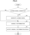
- FIG. 5 is a flow chart illustrating an example of processing of the control device 40 of the device 20 according to the embodiment.
- the determining unit 42 determines whether to generate a learned model that estimates values relating to the components included in the device 20.
- the values relating to the components included in the device 20 may include, for example, measurement values measured by each of the sensors of the device 20.
- the values relating to the components included in the device 20 may include, for example, at least one of the following: the outside air temperature, the inlet tube temperature, the discharge tube temperature, the heat exchanger temperature, the supercooling heat exchange outlet temperature, the receiver liquid tube temperature, the accumulator inlet temperature, the high pressure, the low pressure, the inverter current value, the inverter rotational speed, and the electromagnetic valve opening degree of the outdoor unit.
- the outside air temperature may be, for example, the outside air temperature measured by the thermistor 215.
- the intake tube temperature is, for example, the temperature of the refrigerant taken into the compressor 201 measured by the thermistor 226.
- the discharge tube temperature is, for example, the temperature of the refrigerant discharged from the compressor 201 measured by the thermistor 216.
- the heat exchange temperature may be, for example, the liquid tube temperature of the outdoor heat exchanger 202 measured by the thermistor 218.
- the supercooling heat exchange outlet temperature may be, for example, at least one of the liquid tube temperature of the supercooling heat exchanger 213 measured by the thermistor 219 and the evaporation-side gas tube temperature of the supercooling heat exchanger 213 measured by the thermistor 220.
- the receiver fluid tube temperature may be, for example, the fluid tube temperature measured by a sensor (thermistor) that detects the fluid tube temperature at the inlet of the receiver when the outdoor unit 2000 has a receiver (refrigerant quantity adjustment container) instead of or in addition to the accumulator 225.
- the accumulator inlet temperature may be the gas tube temperature at the inlet of the accumulator 225 as measured by the thermistor 217.
- the high pressure may be, for example, the high pressure measured by the high pressure sensor 209.
- the low pressure may be, for example, the low pressure measured by the low pressure sensor 210.
- the inverter current value is, for example, the current value supplied to the inverter that changes the rotational speed of the motor of the compressor 201.
- the inverter rotational speed may be, for example, the number of revolutions per unit time (rotational speed) of the motor of the compressor 201.
- the electromagnetic valve opening of the outdoor unit is, for example, the opening of the electromagnetic valve 205, the electromagnetic valve 206, the electromagnetic valve 207, etc.
- the determining unit 42 may determine whether to generate the learned model based on at least one of the measurement values measured by each of the sensors of the device 20, the anomaly diagnosis result of the device 20, the result of the control on the device 20, and the conditions relating to the device 20.
- the determining unit 42 may determine the environment in which the device 20 is used based on the measurement values measured by each of the sensors of the device 20, and when the environment satisfies a predetermined condition, the determining unit 42 may determine that a learned model is to be generated. In this case, the determining unit 42 may determine that the learned model is to be generated if, for example, the transition of the outside air temperature measured by the thermistor 215 satisfies a predetermined condition. This can reduce the decrease in the accuracy of anomaly diagnosis caused by the use of a default inference model when, for example, the device 20 is installed in an extremely cold area or a subtropical location.
- the determining unit 42 may determine that the learned model is to be generated when the information on the property where the device 20 is installed satisfies a predetermined condition.
- the information on the property where the device 20 is installed may be set in the device 20 by a worker, etc., when the device 20 is installed on the property, for example. This can reduce the decrease in the accuracy of anomaly diagnosis caused by the use of a default inference model when, for example, the device 20 is installed in an extremely cold area or a subtropical location.
- the determining unit 42 may also determine that the learned model is to be generated when the machine type of the device 20 satisfies a predetermined condition. This can reduce the decrease in the accuracy of anomaly diagnosis caused by the use of a default inference model when, for example, when the device 20 is a machine type with low air-conditioning capacity, and the device 20 is installed in an extremely cold area or a subtropical location, the property has extremely high or low insulation performance, or the property is a store with a large number of visitors, etc.
- the determining unit 42 may first cause the inference unit 43 to estimate the value relating to the component of the device 20 by a predetermined estimation method based on at least one of the measurement values measured by each of the sensors of the device 20, the anomaly diagnosis result of the device 20, and the control result for the device 20.
- the predetermined estimation method may be, for example, an estimation method for each machine type of the device 20 that is set in advance at the time of factory shipment of the device 20.
- the predetermined estimation method may be, for example, a method using AI (Artificial Intelligence) that estimates values relating to components of the device 20 in an average usage environment of the device 20.
- AI Artificial Intelligence
- Measurement values measured by each of the sensors of the device 20 may include, for example, a history of values relating to the components of the device 20 described above.
- the determining unit 42 may determine that the learned model is to be generated if the error (degree of divergence) between the value estimated by the inference unit 43 according to a predetermined estimation method and the measurement value of the value relating to the components of the device 20 is greater than or equal to a threshold.
- the anomaly diagnosis results of the device 20 may include a set of information, including a history of measurement values measured made by each of the sensors of the device 20 and information indicating the results of the anomaly diagnosis set by the maintenance personnel (field engineer), etc.
- the determining unit 42 may determine that a learned model is to be generated if, for example, the degree of divergence between the anomaly determination result obtained by the anomaly determining unit 45 based on the value estimated by the inference unit 43 according to the predetermined estimation method and the actual measurement value measured by each of the sensors of the device 20, and the anomaly diagnosis result set by the maintenance personnel, etc., is greater than or equal to a threshold.
- the control result for the device 20 may include a control signal (an instruction) from the control device 40 to each unit of the device 20, the operation mode and set temperature set by the user by a remote control, etc., and a history of measurement values measured by each of the sensors of the device 20.
- the determining unit 42 may determine that the learned model is to be generated if, for example, the error (degree of divergence) between the actual measurement value of the feedback value for the control signal and the feedback value estimated by the inference unit 43 by the predetermined estimation method is greater than or equal to a threshold.
- step S1 When it is determined that the learned model is to be generated (YES in step S1), the generating unit 44 generates the learned model unique to the device 20 by machine learning (step S2).
- the generating unit 44 may generate the learned model based on the learning data acquired when the components of the device 20 are normal.
- the generating unit 44 may use the data acquired by the acquiring unit 41 within a predetermined period (for example, within two years) from the date and time when the device 20 is installed as learning data acquired when the components of the device 20 are normal.
- a predetermined period for example, within two years
- appropriate learning can be performed, even in a case where, for example, the failure rate of the components of the device 20 follows the bathtub curve (failure rate curve), and after a certain period of time passes to enter a wear failure period, the failure rate rapidly increases due to aging deterioration, etc.
- the generating unit 44 may record, for example, the date and time when the device 20 is first started by the user as the date and time when the device 20 is installed. Also, the date and time when the device 20 is installed may be set by a worker or the like.
- the generating unit 44 may use, as the learning data, a data set in which at least one of the measurement values measured by each of the sensors of the device 20, the anomaly diagnosis result of the device 20, and the control result for the device 20 is used as an explanatory variable, and the measurement value of the value relating to the component is used as the correct answer label.
- the generating unit 44 may perform machine learning by, for example, neural network, support vector machine (SVM), logistic regression, random forest, k-nearest neighbors, etc.
- the anomaly determining unit 45 determines (diagnoses) the anomaly of the components, etc., of the device 20 based on the measurement values measured by each of the sensors of the device 20 (step S3).
- the anomaly determining unit 45 causes the inference unit 43 to calculate (inference, estimate) the value relating to the components included in the device 20.
- the anomaly determining unit 45 causes the inference unit 43 to calculate (inference, estimate) the value relating to the components included in the device 20 by using the learned model.
- the anomaly determining unit 45 causes the inference unit 43 to calculate the value relating to the components included in the device 20 by using the predetermined estimation method described above.
- the anomaly determining unit 45 may determine that the components have an anomaly.
- the determining unit 42 may determine which of the default inference model and the learned model unique to the device 20 generated by the generating unit 44 is to be used in order to cause the anomaly determining unit 45 to perform the anomaly determination.
- the anomaly determination using a default inference model can be performed.
- the determining unit 42 may calculate the first error between the first estimation value of the value relating to the component of the device 20 estimated by the inference unit 43 by using the predetermined estimation method and the actual measurement value of the value relating to the component. Then, the determining unit 42 may calculate the second error between the second estimation value of the value relating to the component estimated by the learned model by the inference unit 43 and the actual measurement value of the value relating to the component.
- the determining unit 42 may determine which inference model among the predetermined estimation method and the estimation method using the learned model is to be used to cause the anomaly determining unit 45 to perform the anomaly determination. Then, the anomaly determining unit 45 may cause the inference unit 43 to perform the inference by using the inference model determined by the determining unit 42.
- the anomaly determination unit may slacken the anomaly determination for the device 20 until the learned model is generated.
- erroneous anomaly determination can be reduced by inference using a default inference model that is determined to have low accuracy of anomaly determination.
- the anomaly determining unit 45 determines that the component has an anomaly.
- the anomaly determining unit 45 may determine that the component does not have an anomaly.
- the anomaly determining unit 45 determines that the component has an anomaly when the error between the estimation value and the measurement value of the value relating to the component of the device 20 is greater than or equal to the second threshold, which is greater than the first threshold. On the other hand, when the error is not greater than or equal to the second threshold, the anomaly determining unit 45 may determine that the component does not have an anomaly.
- the anomaly determining unit 45 outputs the anomaly determination result of the device 20 (step S4).
- the anomaly determining unit 45 may display the anomaly determination result on the display unit of the remote control or the like of the device 20.
- the anomaly determining unit 45 may also notify the anomaly determination result to an external device such as the information processing apparatus 10A.
- Each functional unit of the control device 40 of the device 20, the information processing apparatus 10A, and the information processing apparatus 10B may be implemented by cloud computing provided by, for example, one or more computers.
Landscapes
- Engineering & Computer Science (AREA)
- Physics & Mathematics (AREA)
- General Physics & Mathematics (AREA)
- Theoretical Computer Science (AREA)
- Automation & Control Theory (AREA)
- Artificial Intelligence (AREA)
- Evolutionary Computation (AREA)
- General Engineering & Computer Science (AREA)
- Mathematical Physics (AREA)
- Software Systems (AREA)
- Data Mining & Analysis (AREA)
- Computing Systems (AREA)
- Computational Linguistics (AREA)
- Computer Vision & Pattern Recognition (AREA)
- Medical Informatics (AREA)
- Health & Medical Sciences (AREA)
- Biomedical Technology (AREA)
- Chemical & Material Sciences (AREA)
- Combustion & Propulsion (AREA)
- Mechanical Engineering (AREA)
- Testing And Monitoring For Control Systems (AREA)
- Air Conditioning Control Device (AREA)
- Testing Of Devices, Machine Parts, Or Other Structures Thereof (AREA)
Claims (7)
- Appareil de traitement de l'information (10) comprenant :un module de détermination (42) configuré pour déterminer la génération éventuelle d'un modèle appris, qui estime une valeur relative à un composant compris dans un dispositif (20), d'après au moins un d'une valeur de mesure mesurée par chaque capteur du dispositif, du résultat d'un diagnostic d'anomalie du dispositif (20), d'un résultat du contrôle du dispositif (20), ou d'un état relatif au dispositif (20),un module d'estimation configuré pour estimer la valeur relative au composant par un procédé d'estimation prédéterminé, basé sur au moins un d'une valeur de mesure mesurée par chaque capteur (20) du dispositif, du résultat d'un diagnostic d'anomalie du dispositif (20), ou du résultat du contrôle du dispositif (20),le module de détermination (42) étant configuré pour décider de générer le modèle appris, lorsqu'une erreur entre la valeur estimée par le module d'estimation et une valeur de mesure effective de la valeur relative au composant est supérieure ou égale à un seuil,l'appareil de traitement de l'information (10) étant caractérisé par :un module de détermination des anomalies (45) configuré pour déterminer si le composant présente une anomalie, le module de détermination (42) décidant de ne pas générer le modèle appris, et l'erreur entre la valeur d'estimation et la valeur de mesure effective de la valeur relative au composant étant supérieure ou égale à un premier seuil, etpour déterminer si le composant présente une anomalie, lorsque le module de détermination (42) décide de générer le modèle appris, et l'erreur entre la valeur d'estimation et la valeur de mesure effective de la valeur relative au composant est supérieure ou égale à un deuxième seuil, qui est supérieur au premier seuil.
- Appareil de traitement de l'information (10) selon la revendication 1,
le module de détermination (42) étant configuré pour décider de générer le modèle appris, lorsqu'au moins un d'un environnement dans lequel le dispositif (20) est utilisé, déterminé en fonction de la valeur de mesure mesurée par chaque capteur du dispositif (20), d'informations sur un bien immobilier dans lequel le dispositif (20) est installé, ou d'un type de machine du dispositif (20), répond à une condition prédéterminée. - Appareil de traitement de l'information (10) selon une quelconque des revendications 1 à 2, comprenant en outre :
un module de génération (44) configuré pour générer le modèle appris en fonction d'un ensemble de données lorsque le composant est normal, dans lequel au moins un d'une valeur de mesure mesurée par chaque capteur du dispositif (20), du résultat du diagnostic d'anomalie du dispositif (20), ou du résultat du contrôle du dispositif (20) est une variable explicative, et la valeur de mesure effective de la valeur relative au composant est une étiquette de bonne réponse. - Appareil de traitement de l'information (10) selon une quelconque des revendications 1 à 3, le module de détermination (42) étant configuré pour déterminer un procédé d'estimation pour estimer la valeur relative au composant pour détecter une anomalie du composant, parmi le procédé d'estimation prédéterminé et un procédé d'estimation utilisant le modèle appris, d'après une première erreur entre une première valeur d'estimation de la valeur relative au composant, estimée par le procédé d'estimation prédéterminé, et une deuxième erreur entre une deuxième valeur d'estimation de la valeur relative au composant, estimée par le modèle appris et la valeur de mesure effective.
- Appareil de traitement de l'information (10) selon une quelconque des revendications 1 à 4, la valeur relative au composant comprenant au moins une d'une température de l'air extérieur, d'une température du tube d'admission, d'une température du tube d'évacuation, d'une température d'échange de chaleur, d'une température de sortie d'échange de chaleur de sur-refroidissement, d'une température du tube de liquide du récepteur, d'une température d'entrée de l'accumulateur, d'une haute pression, d'une basse pression, d'une valeur du courant d'inverseur, d'une vitesse de rotation de l'inverseur, ou d'un degré d'ouverture de vanne électromagnétique d'un moteur d'extérieur.
- Procédé de traitement de l'information dans lequel un appareil de traitement de l'information (10) exécute un procédé permettantde déterminer, d'après au moins un d'une valeur de mesure mesurée par chaque capteur du dispositif (20), du résultat d'un diagnostic d'anomalie du dispositif (20), d'un résultat du contrôle du dispositif (20), ou d'un état relatif au dispositif, si un modèle appris, estimant une valeur relative à un composant intégré dans un dispositif (20), doit être généré, etd'estimer la valeur relative au composant par un procédé d'estimation prédéterminé, basé sur au moins un de la valeur de mesure mesurée par chaque capteur du dispositif (20), du résultat d'un diagnostic d'anomalie du dispositif (20), ou du résultat du contrôle du dispositif (20), comprenantla détermination de générer le modèle appris lorsqu'une erreur entre la valeur estimée par le module d'estimation et une valeur de mesure effective de la valeur relative au composant est supérieure ou égale à un seuil, le procédé d'estimation de l'information étant caractérisé par :la détermination de la présence d'une anomalie dans le composant, lors de la décision de ne pas générer le modèle appris, et l'erreur entre la valeur d'estimation et la valeur de mesure effective de la valeur relative au composant étant supérieure ou égale à un premier seuil, etla détermination de la présence éventuelle d'une anomalie du composant lors de la décision de ne pas générer le modèle appris, et l'erreur entre la valeur d'estimation et la valeur de mesure effective de la valeur relative au composant étant supérieure ou égale à un deuxième seuil, qui est supérieur au premier seuil.
- Programme donnant lieu à l'exécution, par un appareil de traitement de l'information, du procédé de traitement de l'information selon la revendication 6.
Applications Claiming Priority (2)
| Application Number | Priority Date | Filing Date | Title |
|---|---|---|---|
| JP2020158989A JP7093031B2 (ja) | 2020-09-23 | 2020-09-23 | 情報処理装置、情報処理方法、及びプログラム |
| PCT/JP2021/034603 WO2022065309A1 (fr) | 2020-09-23 | 2021-09-21 | Dispositif de traitement d'informations, procédé de traitement d'informations et programme |
Publications (3)
| Publication Number | Publication Date |
|---|---|
| EP4220320A1 EP4220320A1 (fr) | 2023-08-02 |
| EP4220320A4 EP4220320A4 (fr) | 2024-04-03 |
| EP4220320B1 true EP4220320B1 (fr) | 2025-02-26 |
Family
ID=80845491
Family Applications (1)
| Application Number | Title | Priority Date | Filing Date |
|---|---|---|---|
| EP21872438.3A Active EP4220320B1 (fr) | 2020-09-23 | 2021-09-21 | Dispositif de traitement d'informations, procédé de traitement d'informations et programme |
Country Status (6)
| Country | Link |
|---|---|
| US (1) | US11774955B1 (fr) |
| EP (1) | EP4220320B1 (fr) |
| JP (1) | JP7093031B2 (fr) |
| CN (1) | CN116209964B (fr) |
| ES (1) | ES3014882T3 (fr) |
| WO (1) | WO2022065309A1 (fr) |
Families Citing this family (4)
| Publication number | Priority date | Publication date | Assignee | Title |
|---|---|---|---|---|
| JP7542417B2 (ja) * | 2019-12-27 | 2024-08-30 | 株式会社Screenホールディングス | 基板処理装置、基板処理方法、基板処理システム、及び学習用データの生成方法 |
| JP7761076B2 (ja) * | 2024-03-21 | 2025-10-28 | 株式会社富士通ゼネラル | 故障推定装置、故障推定方法、空気調和システム及び空気調和機 |
| WO2025197752A1 (fr) * | 2024-03-21 | 2025-09-25 | 株式会社富士通ゼネラル | Dispositif de détermination d'état, procédé de détermination d'état, dispositif d'estimation de défaillance, procédé d'estimation de défaillance, système de climatisation et climatiseur |
| JP2025145104A (ja) * | 2024-03-21 | 2025-10-03 | 株式会社富士通ゼネラル | 状態判定装置、状態判定方法、空気調和システム及び空気調和機 |
Family Cites Families (29)
| Publication number | Priority date | Publication date | Assignee | Title |
|---|---|---|---|---|
| JPS57328Y2 (fr) | 1976-11-13 | 1982-01-06 | ||
| US5659593A (en) * | 1994-11-30 | 1997-08-19 | Lucent Technologies Inc. | Detection of deviations in monitored patterns |
| US7647645B2 (en) * | 2003-07-23 | 2010-01-12 | Omon Ayodele Edeki | System and method for securing computer system against unauthorized access |
| US7480640B1 (en) * | 2003-12-16 | 2009-01-20 | Quantum Leap Research, Inc. | Automated method and system for generating models from data |
| US7260501B2 (en) * | 2004-04-21 | 2007-08-21 | University Of Connecticut | Intelligent model-based diagnostics for system monitoring, diagnosis and maintenance |
| JP4635194B2 (ja) | 2004-12-02 | 2011-02-16 | 財団法人石油産業活性化センター | 異常検知装置 |
| JP2009002650A (ja) | 2008-10-06 | 2009-01-08 | Daikin Ind Ltd | 異常診断システム |
| WO2010118255A2 (fr) * | 2009-04-08 | 2010-10-14 | The University Of North Carolina At Chapel Hill | Procédés, systèmes et produits-programmes informatiques permettant une détection d'anomalie de performance de serveur de réseau |
| US20120137367A1 (en) * | 2009-11-06 | 2012-05-31 | Cataphora, Inc. | Continuous anomaly detection based on behavior modeling and heterogeneous information analysis |
| WO2011121726A1 (fr) | 2010-03-30 | 2011-10-06 | 株式会社 東芝 | Dispositif de détection d'anomalie |
| JP5369246B1 (ja) | 2013-07-10 | 2013-12-18 | 株式会社日立パワーソリューションズ | 異常予兆診断装置及び異常予兆診断方法 |
| JP2015179443A (ja) | 2014-03-19 | 2015-10-08 | 株式会社東芝 | 診断モデル生成装置、診断用モデル生成方法、及び異常診断装置 |
| US10270788B2 (en) * | 2016-06-06 | 2019-04-23 | Netskope, Inc. | Machine learning based anomaly detection |
| CN106019138B (zh) | 2016-07-25 | 2018-10-19 | 深圳供电局有限公司 | 一种高压断路器机械故障的在线诊断方法 |
| WO2018057469A1 (fr) * | 2016-09-21 | 2018-03-29 | Scianta Analytics, LLC | Système de modélisation cognitive |
| JP6869755B2 (ja) | 2017-03-07 | 2021-05-12 | オークマ株式会社 | 状態診断装置 |
| JP6720402B2 (ja) * | 2017-03-21 | 2020-07-08 | 株式会社Preferred Networks | サーバ装置、学習済モデル提供プログラム、学習済モデル提供方法及び学習済モデル提供システム |
| US10212024B2 (en) * | 2017-06-02 | 2019-02-19 | Sas Institute Inc. | Techniques for multi-stage analysis of measurement data with event stream processing |
| JP2019016209A (ja) | 2017-07-07 | 2019-01-31 | 株式会社東芝 | 診断装置、診断方法およびコンピュータプログラム |
| JP6698604B2 (ja) * | 2017-09-29 | 2020-05-27 | ファナック株式会社 | 数値制御システム、及び工具状態検知方法 |
| JP2019066135A (ja) * | 2017-10-04 | 2019-04-25 | ファナック株式会社 | 空調制御システム |
| US11663067B2 (en) * | 2017-12-15 | 2023-05-30 | International Business Machines Corporation | Computerized high-speed anomaly detection |
| US11761556B2 (en) | 2018-06-06 | 2023-09-19 | Kitz Corporation | Valve wear state grasping method and system using valve stem angular velocity |
| JP2020067762A (ja) | 2018-10-23 | 2020-04-30 | トヨタ自動車株式会社 | 制御支援装置、機器制御装置、制御支援方法、制御支援プログラム、コンピュータを機能させるための学習済みモデル、および学習済みモデルの生成方法 |
| JP6848949B2 (ja) * | 2018-10-25 | 2021-03-24 | トヨタ自動車株式会社 | 制御支援装置、車両、および制御支援システム |
| US20190171950A1 (en) * | 2019-02-10 | 2019-06-06 | Kumar Srivastava | Method and system for auto learning, artificial intelligence (ai) applications development, operationalization and execution |
| JP6828762B2 (ja) | 2019-03-15 | 2021-02-10 | ダイキン工業株式会社 | 機械学習装置、及び、磁気軸受装置 |
| JP7233023B2 (ja) | 2019-03-25 | 2023-03-06 | パナソニックIpマネジメント株式会社 | 開閉装置 |
| CN111442483B (zh) * | 2020-03-30 | 2021-12-21 | 广东美的制冷设备有限公司 | 空气调节设备及其控制方法、装置、电子设备 |
-
2020
- 2020-09-23 JP JP2020158989A patent/JP7093031B2/ja active Active
-
2021
- 2021-09-21 ES ES21872438T patent/ES3014882T3/es active Active
- 2021-09-21 US US18/245,421 patent/US11774955B1/en active Active
- 2021-09-21 CN CN202180064505.2A patent/CN116209964B/zh active Active
- 2021-09-21 EP EP21872438.3A patent/EP4220320B1/fr active Active
- 2021-09-21 WO PCT/JP2021/034603 patent/WO2022065309A1/fr not_active Ceased
Also Published As
| Publication number | Publication date |
|---|---|
| WO2022065309A1 (fr) | 2022-03-31 |
| US11774955B1 (en) | 2023-10-03 |
| EP4220320A1 (fr) | 2023-08-02 |
| ES3014882T3 (en) | 2025-04-28 |
| JP7093031B2 (ja) | 2022-06-29 |
| CN116209964A (zh) | 2023-06-02 |
| US20230288921A1 (en) | 2023-09-14 |
| JP2022052545A (ja) | 2022-04-04 |
| EP4220320A4 (fr) | 2024-04-03 |
| CN116209964B (zh) | 2024-04-02 |
Similar Documents
| Publication | Publication Date | Title |
|---|---|---|
| EP4220320B1 (fr) | Dispositif de traitement d'informations, procédé de traitement d'informations et programme | |
| CN110234943B (zh) | 用于冷却系统的低充注检测系统 | |
| US12405019B2 (en) | Air conditioning system, abnormality estimation method for air conditioning system, air conditioner, and abnormality estimation method for air conditioner | |
| EP3859249B1 (fr) | Dispositif de détermination de fuite de fluide frigorigène, dispositif de congélation comprenant ce dispositif de détermination de fuite de fluide frigorigène et procédé de détermination de fuite de fluide frigorigène | |
| US11609010B2 (en) | Detection of refrigerant side faults | |
| CN108027186A (zh) | 用于制冷系统的维护和诊断 | |
| EP1782141A1 (fr) | Systeme et procede pour la detection de baisse de performance sur systeme de refrigeration | |
| US20120031985A1 (en) | Fault tolerant appliance | |
| AU2021316340A1 (en) | Air conditioner | |
| JP7284441B1 (ja) | 異常診断装置、方法、およびプログラム | |
| US20230250985A1 (en) | Generation method, program, information processing apparatus, information processing method, and trained model | |
| CN119213269A (zh) | 预测装置、冷冻系统、预测方法及预测程序 | |
| CN116097046B (zh) | 生成方法、信息处理装置、信息处理方法及学习完毕模型 | |
| EP4502501A1 (fr) | Climatiseur | |
| WO2026048158A1 (fr) | Dispositif et procédé de détection de fuite de fluide frigorigène | |
| WO2026061842A1 (fr) | Procédé de détection d'une dégradation de performances d'un système à compression de vapeur | |
| JP2026043246A (ja) | 冷媒漏洩検知装置および方法 | |
| CN121953390A (zh) | 一种空调系统及其控制方法 | |
| CN121576681A (zh) | 空调器控制方法、系统、空调器及计算机程序产品 | |
| CN116697644A (zh) | 智能温度调节设备及控制方法 | |
| CN121761429A (zh) | 一种空调系统及其控制方法 | |
| CN119222711A (zh) | 蒸发器防冻结方法、装置、室外机、空调设备和存储介质 |
Legal Events
| Date | Code | Title | Description |
|---|---|---|---|
| STAA | Information on the status of an ep patent application or granted ep patent |
Free format text: STATUS: THE INTERNATIONAL PUBLICATION HAS BEEN MADE |
|
| PUAI | Public reference made under article 153(3) epc to a published international application that has entered the european phase |
Free format text: ORIGINAL CODE: 0009012 |
|
| STAA | Information on the status of an ep patent application or granted ep patent |
Free format text: STATUS: REQUEST FOR EXAMINATION WAS MADE |
|
| 17P | Request for examination filed |
Effective date: 20230323 |
|
| AK | Designated contracting states |
Kind code of ref document: A1 Designated state(s): AL AT BE BG CH CY CZ DE DK EE ES FI FR GB GR HR HU IE IS IT LI LT LU LV MC MK MT NL NO PL PT RO RS SE SI SK SM TR |
|
| DAV | Request for validation of the european patent (deleted) | ||
| DAX | Request for extension of the european patent (deleted) | ||
| P01 | Opt-out of the competence of the unified patent court (upc) registered |
Effective date: 20231201 |
|
| A4 | Supplementary search report drawn up and despatched |
Effective date: 20240301 |
|
| RIC1 | Information provided on ipc code assigned before grant |
Ipc: G06N 20/00 20190101ALI20240226BHEP Ipc: G01M 99/00 20110101ALI20240226BHEP Ipc: G05B 23/02 20060101AFI20240226BHEP |
|
| REG | Reference to a national code |
Ref legal event code: R079 Ipc: F24F0011380000 Ref country code: DE Ref legal event code: R079 Ref document number: 602021026926 Country of ref document: DE Free format text: PREVIOUS MAIN CLASS: G05B0023020000 Ipc: F24F0011380000 |
|
| GRAP | Despatch of communication of intention to grant a patent |
Free format text: ORIGINAL CODE: EPIDOSNIGR1 |
|
| STAA | Information on the status of an ep patent application or granted ep patent |
Free format text: STATUS: GRANT OF PATENT IS INTENDED |
|
| RIC1 | Information provided on ipc code assigned before grant |
Ipc: G06N 20/00 20190101ALI20241114BHEP Ipc: G01M 99/00 20110101ALI20241114BHEP Ipc: G05B 23/02 20060101ALI20241114BHEP Ipc: F24F 11/38 20180101AFI20241114BHEP |
|
| INTG | Intention to grant announced |
Effective date: 20241128 |
|
| GRAS | Grant fee paid |
Free format text: ORIGINAL CODE: EPIDOSNIGR3 |
|
| GRAA | (expected) grant |
Free format text: ORIGINAL CODE: 0009210 |
|
| STAA | Information on the status of an ep patent application or granted ep patent |
Free format text: STATUS: THE PATENT HAS BEEN GRANTED |
|
| RIN1 | Information on inventor provided before grant (corrected) |
Inventor name: KURODA, KOUHEI |
|
| AK | Designated contracting states |
Kind code of ref document: B1 Designated state(s): AL AT BE BG CH CY CZ DE DK EE ES FI FR GB GR HR HU IE IS IT LI LT LU LV MC MK MT NL NO PL PT RO RS SE SI SK SM TR |
|
| REG | Reference to a national code |
Ref country code: GB Ref legal event code: FG4D |
|
| REG | Reference to a national code |
Ref country code: CH Ref legal event code: EP |
|
| REG | Reference to a national code |
Ref country code: DE Ref legal event code: R096 Ref document number: 602021026926 Country of ref document: DE |
|
| REG | Reference to a national code |
Ref country code: IE Ref legal event code: FG4D |
|
| REG | Reference to a national code |
Ref country code: NL Ref legal event code: MP Effective date: 20250226 |
|
| PG25 | Lapsed in a contracting state [announced via postgrant information from national office to epo] |
Ref country code: RS Free format text: LAPSE BECAUSE OF FAILURE TO SUBMIT A TRANSLATION OF THE DESCRIPTION OR TO PAY THE FEE WITHIN THE PRESCRIBED TIME-LIMIT Effective date: 20250526 |
|
| PG25 | Lapsed in a contracting state [announced via postgrant information from national office to epo] |
Ref country code: FI Free format text: LAPSE BECAUSE OF FAILURE TO SUBMIT A TRANSLATION OF THE DESCRIPTION OR TO PAY THE FEE WITHIN THE PRESCRIBED TIME-LIMIT Effective date: 20250226 |
|
| PG25 | Lapsed in a contracting state [announced via postgrant information from national office to epo] |
Ref country code: PL Free format text: LAPSE BECAUSE OF FAILURE TO SUBMIT A TRANSLATION OF THE DESCRIPTION OR TO PAY THE FEE WITHIN THE PRESCRIBED TIME-LIMIT Effective date: 20250226 |
|
| REG | Reference to a national code |
Ref country code: LT Ref legal event code: MG9D |
|
| PG25 | Lapsed in a contracting state [announced via postgrant information from national office to epo] |
Ref country code: IS Free format text: LAPSE BECAUSE OF FAILURE TO SUBMIT A TRANSLATION OF THE DESCRIPTION OR TO PAY THE FEE WITHIN THE PRESCRIBED TIME-LIMIT Effective date: 20250626 Ref country code: NO Free format text: LAPSE BECAUSE OF FAILURE TO SUBMIT A TRANSLATION OF THE DESCRIPTION OR TO PAY THE FEE WITHIN THE PRESCRIBED TIME-LIMIT Effective date: 20250526 |
|
| PG25 | Lapsed in a contracting state [announced via postgrant information from national office to epo] |
Ref country code: NL Free format text: LAPSE BECAUSE OF FAILURE TO SUBMIT A TRANSLATION OF THE DESCRIPTION OR TO PAY THE FEE WITHIN THE PRESCRIBED TIME-LIMIT Effective date: 20250226 |
|
| PG25 | Lapsed in a contracting state [announced via postgrant information from national office to epo] |
Ref country code: HR Free format text: LAPSE BECAUSE OF FAILURE TO SUBMIT A TRANSLATION OF THE DESCRIPTION OR TO PAY THE FEE WITHIN THE PRESCRIBED TIME-LIMIT Effective date: 20250226 |
|
| PG25 | Lapsed in a contracting state [announced via postgrant information from national office to epo] |
Ref country code: PT Free format text: LAPSE BECAUSE OF FAILURE TO SUBMIT A TRANSLATION OF THE DESCRIPTION OR TO PAY THE FEE WITHIN THE PRESCRIBED TIME-LIMIT Effective date: 20250626 Ref country code: LV Free format text: LAPSE BECAUSE OF FAILURE TO SUBMIT A TRANSLATION OF THE DESCRIPTION OR TO PAY THE FEE WITHIN THE PRESCRIBED TIME-LIMIT Effective date: 20250226 |
|
| PG25 | Lapsed in a contracting state [announced via postgrant information from national office to epo] |
Ref country code: BG Free format text: LAPSE BECAUSE OF FAILURE TO SUBMIT A TRANSLATION OF THE DESCRIPTION OR TO PAY THE FEE WITHIN THE PRESCRIBED TIME-LIMIT Effective date: 20250226 Ref country code: GR Free format text: LAPSE BECAUSE OF FAILURE TO SUBMIT A TRANSLATION OF THE DESCRIPTION OR TO PAY THE FEE WITHIN THE PRESCRIBED TIME-LIMIT Effective date: 20250527 |
|
| REG | Reference to a national code |
Ref country code: AT Ref legal event code: MK05 Ref document number: 1770970 Country of ref document: AT Kind code of ref document: T Effective date: 20250226 |
|
| PG25 | Lapsed in a contracting state [announced via postgrant information from national office to epo] |
Ref country code: SE Free format text: LAPSE BECAUSE OF FAILURE TO SUBMIT A TRANSLATION OF THE DESCRIPTION OR TO PAY THE FEE WITHIN THE PRESCRIBED TIME-LIMIT Effective date: 20250226 |
|
| PG25 | Lapsed in a contracting state [announced via postgrant information from national office to epo] |
Ref country code: SM Free format text: LAPSE BECAUSE OF FAILURE TO SUBMIT A TRANSLATION OF THE DESCRIPTION OR TO PAY THE FEE WITHIN THE PRESCRIBED TIME-LIMIT Effective date: 20250226 |
|
| PG25 | Lapsed in a contracting state [announced via postgrant information from national office to epo] |
Ref country code: DK Free format text: LAPSE BECAUSE OF FAILURE TO SUBMIT A TRANSLATION OF THE DESCRIPTION OR TO PAY THE FEE WITHIN THE PRESCRIBED TIME-LIMIT Effective date: 20250226 |
|
| PGFP | Annual fee paid to national office [announced via postgrant information from national office to epo] |
Ref country code: IT Payment date: 20250923 Year of fee payment: 5 |
|
| PGFP | Annual fee paid to national office [announced via postgrant information from national office to epo] |
Ref country code: GB Payment date: 20250919 Year of fee payment: 5 |
|
| PG25 | Lapsed in a contracting state [announced via postgrant information from national office to epo] |
Ref country code: AT Free format text: LAPSE BECAUSE OF FAILURE TO SUBMIT A TRANSLATION OF THE DESCRIPTION OR TO PAY THE FEE WITHIN THE PRESCRIBED TIME-LIMIT Effective date: 20250226 |
|
| PGFP | Annual fee paid to national office [announced via postgrant information from national office to epo] |
Ref country code: FR Payment date: 20250922 Year of fee payment: 5 |
|
| PG25 | Lapsed in a contracting state [announced via postgrant information from national office to epo] |
Ref country code: CZ Free format text: LAPSE BECAUSE OF FAILURE TO SUBMIT A TRANSLATION OF THE DESCRIPTION OR TO PAY THE FEE WITHIN THE PRESCRIBED TIME-LIMIT Effective date: 20250226 Ref country code: EE Free format text: LAPSE BECAUSE OF FAILURE TO SUBMIT A TRANSLATION OF THE DESCRIPTION OR TO PAY THE FEE WITHIN THE PRESCRIBED TIME-LIMIT Effective date: 20250226 |
|
| PG25 | Lapsed in a contracting state [announced via postgrant information from national office to epo] |
Ref country code: RO Free format text: LAPSE BECAUSE OF FAILURE TO SUBMIT A TRANSLATION OF THE DESCRIPTION OR TO PAY THE FEE WITHIN THE PRESCRIBED TIME-LIMIT Effective date: 20250226 |
|
| PG25 | Lapsed in a contracting state [announced via postgrant information from national office to epo] |
Ref country code: SK Free format text: LAPSE BECAUSE OF FAILURE TO SUBMIT A TRANSLATION OF THE DESCRIPTION OR TO PAY THE FEE WITHIN THE PRESCRIBED TIME-LIMIT Effective date: 20250226 |
|
| REG | Reference to a national code |
Ref country code: DE Ref legal event code: R097 Ref document number: 602021026926 Country of ref document: DE |
|
| PLBE | No opposition filed within time limit |
Free format text: ORIGINAL CODE: 0009261 |
|
| STAA | Information on the status of an ep patent application or granted ep patent |
Free format text: STATUS: NO OPPOSITION FILED WITHIN TIME LIMIT |
|
| PGFP | Annual fee paid to national office [announced via postgrant information from national office to epo] |
Ref country code: ES Payment date: 20251030 Year of fee payment: 5 |
|
| 26N | No opposition filed |
Effective date: 20251127 |