EP4220638B1 - Decodierungsvorrichtung und -verfahren und programm - Google Patents
Decodierungsvorrichtung und -verfahren und programm Download PDFInfo
- Publication number
- EP4220638B1 EP4220638B1 EP23168017.4A EP23168017A EP4220638B1 EP 4220638 B1 EP4220638 B1 EP 4220638B1 EP 23168017 A EP23168017 A EP 23168017A EP 4220638 B1 EP4220638 B1 EP 4220638B1
- Authority
- EP
- European Patent Office
- Prior art keywords
- frequency
- power
- low
- frequency subband
- coefficient
- Prior art date
- Legal status (The legal status is an assumption and is not a legal conclusion. Google has not performed a legal analysis and makes no representation as to the accuracy of the status listed.)
- Active
Links
Images










Classifications
-
- G—PHYSICS
- G10—MUSICAL INSTRUMENTS; ACOUSTICS
- G10L—SPEECH ANALYSIS TECHNIQUES OR SPEECH SYNTHESIS; SPEECH RECOGNITION; SPEECH OR VOICE PROCESSING TECHNIQUES; SPEECH OR AUDIO CODING OR DECODING
- G10L21/00—Speech or voice signal processing techniques to produce another audible or non-audible signal, e.g. visual or tactile, in order to modify its quality or its intelligibility
- G10L21/02—Speech enhancement, e.g. noise reduction or echo cancellation
- G10L21/038—Speech enhancement, e.g. noise reduction or echo cancellation using band spreading techniques
- G10L21/0388—Details of processing therefor
-
- G—PHYSICS
- G10—MUSICAL INSTRUMENTS; ACOUSTICS
- G10L—SPEECH ANALYSIS TECHNIQUES OR SPEECH SYNTHESIS; SPEECH RECOGNITION; SPEECH OR VOICE PROCESSING TECHNIQUES; SPEECH OR AUDIO CODING OR DECODING
- G10L19/00—Speech or audio signals analysis-synthesis techniques for redundancy reduction, e.g. in vocoders; Coding or decoding of speech or audio signals, using source filter models or psychoacoustic analysis
- G10L19/008—Multichannel audio signal coding or decoding using interchannel correlation to reduce redundancy, e.g. joint-stereo, intensity-coding or matrixing
-
- G—PHYSICS
- G10—MUSICAL INSTRUMENTS; ACOUSTICS
- G10L—SPEECH ANALYSIS TECHNIQUES OR SPEECH SYNTHESIS; SPEECH RECOGNITION; SPEECH OR VOICE PROCESSING TECHNIQUES; SPEECH OR AUDIO CODING OR DECODING
- G10L25/00—Speech or voice analysis techniques not restricted to a single one of groups G10L15/00 - G10L21/00
- G10L25/03—Speech or voice analysis techniques not restricted to a single one of groups G10L15/00 - G10L21/00 characterised by the type of extracted parameters
- G10L25/18—Speech or voice analysis techniques not restricted to a single one of groups G10L15/00 - G10L21/00 characterised by the type of extracted parameters the extracted parameters being spectral information of each sub-band
-
- G—PHYSICS
- G10—MUSICAL INSTRUMENTS; ACOUSTICS
- G10L—SPEECH ANALYSIS TECHNIQUES OR SPEECH SYNTHESIS; SPEECH RECOGNITION; SPEECH OR VOICE PROCESSING TECHNIQUES; SPEECH OR AUDIO CODING OR DECODING
- G10L25/00—Speech or voice analysis techniques not restricted to a single one of groups G10L15/00 - G10L21/00
- G10L25/03—Speech or voice analysis techniques not restricted to a single one of groups G10L15/00 - G10L21/00 characterised by the type of extracted parameters
- G10L25/21—Speech or voice analysis techniques not restricted to a single one of groups G10L15/00 - G10L21/00 characterised by the type of extracted parameters the extracted parameters being power information
-
- G—PHYSICS
- G10—MUSICAL INSTRUMENTS; ACOUSTICS
- G10L—SPEECH ANALYSIS TECHNIQUES OR SPEECH SYNTHESIS; SPEECH RECOGNITION; SPEECH OR VOICE PROCESSING TECHNIQUES; SPEECH OR AUDIO CODING OR DECODING
- G10L19/00—Speech or audio signals analysis-synthesis techniques for redundancy reduction, e.g. in vocoders; Coding or decoding of speech or audio signals, using source filter models or psychoacoustic analysis
- G10L19/02—Speech or audio signals analysis-synthesis techniques for redundancy reduction, e.g. in vocoders; Coding or decoding of speech or audio signals, using source filter models or psychoacoustic analysis using spectral analysis, e.g. transform vocoders or subband vocoders
-
- G—PHYSICS
- G10—MUSICAL INSTRUMENTS; ACOUSTICS
- G10L—SPEECH ANALYSIS TECHNIQUES OR SPEECH SYNTHESIS; SPEECH RECOGNITION; SPEECH OR VOICE PROCESSING TECHNIQUES; SPEECH OR AUDIO CODING OR DECODING
- G10L19/00—Speech or audio signals analysis-synthesis techniques for redundancy reduction, e.g. in vocoders; Coding or decoding of speech or audio signals, using source filter models or psychoacoustic analysis
- G10L19/02—Speech or audio signals analysis-synthesis techniques for redundancy reduction, e.g. in vocoders; Coding or decoding of speech or audio signals, using source filter models or psychoacoustic analysis using spectral analysis, e.g. transform vocoders or subband vocoders
- G10L19/0204—Speech or audio signals analysis-synthesis techniques for redundancy reduction, e.g. in vocoders; Coding or decoding of speech or audio signals, using source filter models or psychoacoustic analysis using spectral analysis, e.g. transform vocoders or subband vocoders using subband decomposition
- G10L19/0208—Subband vocoders
-
- G—PHYSICS
- G10—MUSICAL INSTRUMENTS; ACOUSTICS
- G10L—SPEECH ANALYSIS TECHNIQUES OR SPEECH SYNTHESIS; SPEECH RECOGNITION; SPEECH OR VOICE PROCESSING TECHNIQUES; SPEECH OR AUDIO CODING OR DECODING
- G10L21/00—Speech or voice signal processing techniques to produce another audible or non-audible signal, e.g. visual or tactile, in order to modify its quality or its intelligibility
- G10L21/04—Time compression or expansion
Definitions
- the present invention relates to an encoding device and method, a decoding device and method, and a program, and specifically relates to an encoding device and method, a decoding device and method, and a program which enable music signals to be played with high sound quality by expanding a frequency band.
- music distribution service to distribute music data via the Internet or the like has been spreading.
- encoded data obtained by encoding music signals is distributed as music data.
- an encoding technique has become the mainstream wherein a bit rate is lowered while suppressing file capacity of encoded data so as not to take time at the time of downloading.
- Such a music signal encoding techniques are roughly divided into an encoding technique such as MP3 (MPEG (Moving Picture Experts Group) Audio Layer 3) (International Standards ISO/IEC 11172-3) and so forth, and an encoding technique such as HE-AAC (High Efficiency MPEG4 AAC) (International Standards ISO/IEC 14496-3) and so forth.
- MP3 MPEG (Moving Picture Experts Group) Audio Layer 3
- HE-AAC High Efficiency MPEG4 AAC
- high-frequency sound may slightly be sensed by the human ear, and accordingly, at the time of generating and outputting sound from music signals after decoding obtained by decoding encoded data, there may be deterioration in sound quality such as loss of sense of presence that the original sound has, or the sound may seem to be muffled.
- HE-AAC characteristic information is extracted from high-frequency signal components, and encoded along with low-frequency signal components.
- a high-frequency characteristic encoding technique With this high-frequency characteristic encoding technique, only characteristic information of high-frequency signal components is encoded as information relating to the high-frequency signal components, and accordingly, encoding efficiency may be improved while suppressing deterioration in sound quality.
- the band expanding technique there is post-processing after decoding of encoded data by the above-mentioned high-frequency deletion encoding technique. With this post-processing, high-frequency signal components lost by encoding are generated from the low-frequency signal components after decoding, thereby expanding the frequency band of the low-frequency signal components (see PTL 1). Note that the frequency band expanding technique according to PTL 1 will hereinafter be referred to as the band expanding technique according to PTL 1.
- a device takes low-frequency signal components after decoding as an input signal, estimates high-frequency power spectrum (hereinafter, referred to as high-frequency frequency envelopment as appropriate) from the power spectrum of the input signals, and generates high-frequency signal components having the high-frequency frequency envelopment from the low-frequency signal components.
- high-frequency frequency envelopment as appropriate
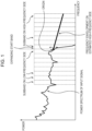
- Fig. 1 illustrates an example of the low-frequency power spectrum after decoding, serving as the input signal, and the estimated high-frequency frequency envelopment.
- Fig. 1 the vertical axis indicates power by a logarithm, and the horizontal axis indicates frequencies.
- the device adds the generated multiple subband signals on the high-frequency side to obtain high-frequency signal components, and further adds the low-frequency signal components thereto and output these.
- music signals after expanding the frequency band approximates to the original music signals. Accordingly, music signals with high sound quality may be played.
- the above-mentioned band expanding technique according to PTL 1 has a feature wherein, with regard to various high-frequency deletion encoding techniques and encoded data with various bit rates, the frequency band regarding music signals after decoding of the encoded data thereof can be expanded.
- the power spectrums of music signals have various shapes, there may be many cases to greatly deviate from the frequency envelopment on the high-frequency side estimated by the band expanding technique according to PTL 1, depending on the types of music signals.
- Fig. 2 illustrates an example of the original power spectrum of a music signal of attack nature (music signal with attack) accompanying temporal rapid change such as strongly hitting a drum once.
- Fig. 2 also illustrates frequency envelopment on the high-frequency side estimated by the band expanding technique according to PTL 1 from signal components on the low-frequency side of a music signal with attack serving as an input signal.
- the original power spectrum on the high-frequency side of the music signal with attack is generally flat.
- the estimated frequency envelopment on the high-frequency side has a predetermined negative inclination, and accordingly, even when adjusting the power at the origin approximate to the original power spectrum, as the frequency increases, difference with the original power spectrum increases.
- the present invention has been made in the light of such situations, and enables music signals to be played with high sound quality by expanding the frequency band.
- the low-pass filter 11 performs filtering of an input signal with a predetermined cutoff frequency, and supplies a low-frequency signal component which is a signal component of low-frequency to the delay circuit 12 as a signal after filtering.
- the band pass filters 13 are configured of band pass filters 13-1 to 13-N each having a different passband.
- the band pass filter 13-i (1 ⁇ i ⁇ N) passes a predetermined passband signal of input signals, and supplies this to the feature amount calculating circuit 14 and high-frequency signal generating circuit 16 as one of the multiple subband signals.
- the high-frequency subband power estimating circuit 15 calculates a high-frequency subband power estimated value which is power of a high-frequency subband signal for each high-frequency subband based on a single or multiple feature amounts from the feature amount calculating circuit 14, and supplies these to the high-frequency signal generating circuit 16.
- the high-frequency signal generating circuit 16 generates a high-frequency signal component which is a high-frequency signal component based on the multiple subband signals from the band pass filters 13, and the multiple high-frequency subband power estimated values from the high-frequency subband power estimating circuit 15 to supply to the high-pass filter 17.
- the band pass filters 13 are applied, but not restricted to this, and a band dividing filter as described in PTL 1 may be applied, for example.
- step S4 the feature amount calculating circuit 14 calculates a single or multiple feature amounts using at least one of the multiple subband signals from the band pass filters 13, and the input signal to supply to the high-frequency subband power estimating circuit 15. Note that, with regard to feature amount calculating processing by the feature amount calculating circuit 14, details thereof will be described later.
- step S7 the high-pass filter 17 subjects the high-frequency signal component from the high-frequency signal generating circuit 16 to filtering, thereby removing noise such as aliasing components to a low frequency included in a high-frequency signal component, and supplying the high-frequency signal component thereof to the signal adder 18.
- step S8 the signal adder 18 adds the low-frequency signal component from the delay circuit 12 and the high-frequency signal component from the high-pass filter 17 to supply this as an output signal.
- the frequency band may be expanded as to a low-frequency signal component after decoding.
- N 4.
- the passbands of the band pass filters 13-1 to 13-4 are predetermined four subbands of 16 subbands obtained by equally dividing the Nyquist frequency of the input signal into 16, respectively, but not restricted to this, and may be predetermined four subbands of 256 subbands obtained by equally dividing the Nyquist frequency of the input signal into 256, respectively. Also, the bandwidths of the band pass filters 13-1 to 13-4 may differ.
- the feature amount calculating circuit 14 calculates, from four subband signals from the band pass filters 13, subband signal power (subband power (hereinafter, also referred to as low-frequency subband power)) for each subband as a feature amount to supply to the high-frequency subband power estimating circuit 15.
- subband power hereinafter, also referred to as low-frequency subband power
- the high-frequency signal generating circuit 16 calculates a low-frequency subband power power(ib, J) of each subband from the multiple subband signals supplied from the band pass filters 13 based on the above-mentioned Expression (1).
- the high-frequency signal generating circuit 16 obtains a gain amount G(ib, J) by the following Expression (3) using the calculated multiple low-frequency subband powers power(ib, J), and the high-frequency subband power estimated value power est (ib, J) calculated based on the above-mentioned Expression (2) by the high-frequency subband power estimating circuit 15.
- Fig. 6 illustrates an example of frequency characteristic of a vocal section which is a section where vocal occupies the majority in a certain input signal, and a high-frequency power spectrum obtained by calculating only low-frequency subband powers as feature amounts to estimate a high-frequency subband power.
- a recessed degree from 4.9 kHz to 11.025 kHz in a frequency region is applied as a feature amount to be used for estimation of a high-frequency subband power of a vocal section.
- the feature amount indicating this recessed degree will be referred to as dip.
- signals in 2048 sample sections included in several frames before and after including the time frame J are subjected to 2048-point FFT (Fast Fourier Transform) to calculate coefficients on the frequency axis.
- the absolute values of the calculated coefficients are subjected to db transform to obtain power spectrums.
- Fig. 7 illustrates an example of the power spectrums thus obtained.
- liftering processing is performed so as to remove components of 1.3 kHz or less, for example.
- each dimension of the power spectrums is taken as time series, and is subjected to a low-pass filter to perform filtering processing, whereby fine components of a spectrum peak may be smoothed.
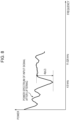
- Fig. 8 illustrates an example of the power spectrum of an input signal after liftering.
- difference between the minimum value and the maximum value of the power spectrum included in a range equivalent to 4.9 kHz to 11.025 kHz is taken as dip dip(J).
- temporal fluctuation of a low-frequency subband power is applied as a feature amount to be used for estimation of a high-frequency subband power of an attack section.
- Temporal fluctuation power d (J) of a low-frequency subband power in a certain time frame J is obtained by the following Expression (8), for example.
- the temporal fluctuation power d (J) of a low-frequency subband power represents a ratio between sum of four low-frequency subband powers in the time frame J, and sum of four low-frequency subband powers in time frame (J-1) which is one frame before the time frame J, and the greater this value is, the greater the temporal fluctuation of power between the frames is, i.e., it may be conceived that the signal included in the time frame J has strong attack nature.
- the power spectrum of the attack section increases toward the right at middle frequency. With the attack sections, such frequency characteristic is frequently exhibited.
- Inclination slope (J) of the middle frequency in a certain time frame J is obtained by the following Expression (9), for example.
- a coefficient w(ib) is a weighting coefficient adjusted so as to weight to high-frequency subband power.
- the feature amount calculating circuit 14 calculates a low-frequency subband power and dip from the four subband signals for each subband from the band pass filters 13 as feature amounts to supply to the high-frequency subband power estimating circuit 15.
- the high-frequency subband power estimating circuit 15 calculates the highest-frequency subband power of the four low-frequency subband powers and the value of the dip regarding a great number of input signals and obtains a mean value and standard deviation regarding each thereof beforehand.
- a mean value of the subband powers is power ave
- standard deviation of the subband powers is power std
- a mean value of the dip is dip ave
- standard deviation of the dip is dip std .
- the high-frequency subband power estimating circuit 15 converts the value dip(J) of the dip using these values such as the following Expression (12) to obtain a dip dip s (J) after conversation.
- dip s J dip J ⁇ dip ave dip std power std + power ave
- an estimated value power est (ib, J) of a subband power of which the index is ib is represented by the following Expression (13) using linear coupling between the four low-frequency subband powers power(id, J) from the feature amount calculating circuit 14, and the dip dip s (J) indicated in Expression (12), for example.
- an estimated value of a high-frequency subband power is calculated by the primary linear coupling, not restricted to this, and for example, may be calculated using linear couplings of multiple feature amounts of several frames before and after the time frame J, or may be calculated using a non-linear function.
- the value of the dip peculiar to a vocal section is used for estimation of a high-frequency subband power, thereby as compared to a case where only the low-frequency subband powers are taken as feature amounts, improving estimation precision of a high-frequency subband power at a vocal section, and reducing unnatural sensations that are readily sensed by the human ear, caused by a high-frequency subband power spectrum being estimated greater then the high-frequency power spectrum of the original signal using the technique wherein only low-frequency subband powers are taken as feature amounts, and accordingly, music signals may be played with higher sound quality.
- the number of subband divisions is increased (e.g., 256 divisions equivalent to 16 times), the number of band divisions by the band pass filters 13 is increased (e.g., 64 equivalent to 16 times), and the number of low-frequency subband powers to be calculated by the feature amount calculating circuit 14 is increased (e.g., 64 equivalent to 16 times), thereby improving the frequency resolution, and enabling a recessed degree to be expressed with low-frequency subband powers alone.
- a high-frequency subband power may be estimated with generally the same precision as estimation of a high-frequency subband power using the above-mentioned dip as a feature amount, using low-frequency subband powers alone.
- the calculation amount is increased by increasing the number of subband divisions, the number of band divisions, and the number of low-frequency subband powers. If we consider that any technique may estimate a high-frequency subband power with similar precision, it is thought that a technique to estimate a high-frequency subband power without increasing the number of subband divisions, using the dip as a feature amount is effective in an aspect of calculator amount.
- a feature amount to be used for estimation of a high-frequency subband power is not restricted to this combination, one or multiple feature amounts described above (low-frequency subband powers, dip, temporal fluctuation of low-frequency subband powers, inclination, temporal fluctuation of inclination, and temporal fluctuation of dip) may be employed. Thus, precision may further be improved with estimation of a high-frequency subband power.
- a parameter peculiar to a section where estimation of a high-frequency subband poer is difficult is employed as a feature amount to be used for estimation of a high-frequency subband power, thereby enabling estimation precision of the section thereof to be improved.
- temporal fluctuation of low-frequency subband powers, inclination, temporal fluctuation of inclination, and temporal fluctuation of dip are parameters peculiar to attack sections, and these parameters are employed as feature amounts, thereby enabling estimation precision of a high-frequency subband power at an attack section to be improved.
- the coefficients C ib (kb), D ib , and E ib in order to obtain suitable coefficients the coefficients C ib (kb), D ib , and E ib for various input signals at the time of estimating the subband power of the frequency expanding band, a technique will be employed wherein learning is performed using a broadband supervisory signal (hereinafter, referred to as broadband supervisory signal) beforehand, and the coefficients C ib (kb), D ib , and E ib are determined based on the learning results thereof.
- broadband supervisory signal hereinafter, referred to as broadband supervisory signal
- a coefficient learning device At the time of performing learning of the coefficients C ib (kb), D ib , and E ib a coefficient learning device will be applied wherein band pass filters having the same pass bandwidths as the band pass filters 13-1 to 13-14 described with reference to Fig. 5 are disposed in a higher frequency than the expanding start band.
- the coefficient learning device performs learning when a broadband supervisory signal is input.
- Fig. 9 illustrates a functional configuration example of a coefficient learning device to perform learning of the coefficients C ib (kb), D ib , and E ib .
- an input signal band-restricted to be input to the frequency band expanding device 10 in Fig. 3 is a signal encoded by the same method as the encoding method subjected at the time of encoding.
- the coefficient learning device 20 is configured of band pass filters 21, a high-frequency subband power calculating circuit 22, a feature amount calculating circuit 23, and a coefficient estimating circuit 24.
- the band pass filters 21 are configured of band pass filters 21-1 to 21-(K+N) each having a different pass band.
- the band pass filter 21-i(1 ⁇ i ⁇ K+N) passes a predetermined pass band signal of an input signal, and supplies this to the high-frequency subband power calculating circuit 22 or feature amount calculating circuit 23 as one of multiple subband signals. Note that, of the band pass filters 21-1 to 21-(K+N), the band pass filters 21-1 to 21-K pass a higher frequency signal than the expanding start band.
- the feature amount calculating circuit 23 calculates the same feature amount as a feature amount calculated by the feature amount calculating circuit 14 of the frequency band expanding device 10 in Fig. 3 for each same frame as a fixed time frame where a high-frequency subband power is calculated by the high-frequency subband power calculation circuit 22. That is to say, the feature amount calculating circuit 23 calculates one or multiple feature amounts using at least one of the multiple subband signals from the band pass filters 21 and the broadband supervisory signal to supply to the coefficient estimating circuit 24.
- the band pass filters 21 divide an input signal (broadband supervisory signal) into (K+N) subband signals.
- the band pass filters 21-1 to 21-K supply higher frequency multiple subband signals than the expanding start band to the high-frequency subband power calculating circuit 22.
- the band pass filters 21-(K+1) to 21-(K+N) supply lower frequency multiple subband signals than the expanding start band to the feature amount calculating circuit 23.
- the high-frequency subband power circuit 22 calculates a high-frequency subband power power(ib, J) for each subband for each fixed time frame for high-frequency multiple subband signals from the band pass filters 21 (band pass filters 21-1 to 21-K).
- the high-frequency subband power power(ib, J) is obtained by the above-mentioned Expression (1).
- the high-frequency subband power calculating circuit 22 supplies the calculated high-frequency subband power to the coefficient estimating circuit 24.
- step S13 the feature amount calculating circuit 23 calculates a feature amount for each same time frame as a fixed time frame where a high-frequency subband power is calculated by the high-frequency subband power calculating circuit 22.
- the feature amount calculating circuit 23 calculates four low-frequency subband powers using four subband signals having the same bands as four subband signals to be input to the feature amount calculating circuit 14 of the frequency band expanding device 10, from the band pass filters 21 (band pass filters 21-(K+1) to 21-(K+4)). Also, the feature amount calculating circuit 23 calculates a dip from the broadband supervisory signal, and calculates a dip dip s (J) based on the above-mentioned Expression (12). The feature amount calculating circuit 23 supplies the calculated four low-frequency subband powers and dip dip s (J) to the coefficient estimating circuit 24 as feature amounts.
- step S14 the coefficient estimating circuit 24 performs estimation of the coefficients C ib (kb), D ib , and E ib based on a great number of combinations between (eb - sb) high-frequency subband powers and the feature amounts (four low-frequency subband powers and dip dip s (J)) supplied from the high-frequency subband power calculating circuit 22 and feature amount calculating circuit 23 at the time frame.
- the coefficient estimating circuit 24 takes, regarding a certain high-frequency subband, five feature amounts (four low-frequency subband powers and dip dip s (J)) as explanatory variables, and takes the high-frequency subband power(ib, J) as an explained variable to perform regression analysis using the least square method, thereby deterring the coefficients C ib (kb), D ib , and E ib in Expression (13).
- the estimating technique for the coefficients C ib (kb), D ib , and E ib is not restricted to the above-mentioned technique, and common various parameter identifying methods may be employed.
- coefficients A ib (kb) and B ib in the above-mentioned Expression (2) may also be obtained by the above-mentioned coefficient learning method.
- the technique for estimating a high-frequency subband power at the high-frequency subband power estimating circuit 15 is not restricted to the above-mentioned example, and a high-frequency subband power may be calculated by the feature amount calculating circuit 14 calculating one or multiple feature amounts (temporal fluctuation of low-frequency subband power, inclination, temporal fluctuation of inclination, and temporal fluctuation of a dip) other than a dip, or linear coupling between multiple feature amounts of multiple frames before and after the time frame J may be employed, or a non-linear function may be employed.
- the coefficient estimating circuit 24 calculate (learn) the coefficients with the same conditions as conditions regarding feature amounts, time frame, and a function to be used at the time of a high-frequency subband power being calculated by the high-frequency subband power estimating circuit 15 of the frequency band expanding device 10.
- the input signal is subjected to encoding processing and decoding processing in the high-frequency characteristic encoding technique by an encoding device and a decoding device.
- An encoding device 30 is configured of a low-pass filter 31, a low-frequency encoding circuit 32, a subband dividing circuit 33, a feature amount calculating circuit 34, a pseudo high-frequency subband power calculating circuit 35, a pseudo high-frequency subband power difference calculating circuit 36, a high-frequency encoding circuit 37, a multiplexing circuit 38, and a low-frequency decoding circuit 39.
- the low-pass filter 31 subjects an input signal to filtering with a predetermined cutoff frequency, and supplies a lower frequency signal (hereinafter, referred to as low-frequency signal) than the cutoff frequency to the low-frequency encoding circuit 32, subband dividing circuit 33 and feature amount calculating circuit 34 as a signal after filtering.
- a lower frequency signal hereinafter, referred to as low-frequency signal
- the low-frequency encoding circuit 32 encodes the low-frequency signal from the low-pass filter 31, and supplies low-frequency encoded data obtained as a result thereof to the multiplexing circuit 38 and low-frequency decoding circuit 39.
- the pseudo high-frequency subband power difference calculated by the pseudo high-frequency subband power difference calculating circuit 36 is supplied to the high-frequency encoding circuit 37.
- the pseudo high-frequency subband power difference clustering circuit 56 calculates the representative vector of each cluster by a great number of pseudo high-frequency subband power difference vectors (a lot of time frames) obtained from the pseudo high-frequency subband power difference from the pseudo high-frequency subband power difference calculating circuit 55 being subjected to clustering to 64 clusters for example.
- clustering according to the k-means method may be applied, for example.
- the pseudo high-frequency subband power difference clustering circuit 56 takes the center-of-gravity vector of each cluster obtained as a result of performing clustering according to the k-means method as the representative vector of each cluster. Note that a technique for clustering and the number of clusters are not restricted to those mentioned above, and another technique may be employed.
- the pseudo high-frequency subband power difference clustering circuit 56 measures distance with the 64 representative vectors using a pseudo high-frequency subband power difference vector obtained from the pseudo high-frequency subband power difference from the pseudo high-frequency subband power difference calculating circuit 55 in the time frame J to determine an index CID(J) of a cluster to which a representative vector to provide the shortest distance belongs.
- the index CID(J) takes an integer from 1 to the number of clusters (64 in this example).
- the pseudo high-frequency subband power difference clustering circuit 56 outputs a representative vector in this manner, and also supplies the index CID(J) to the coefficient estimating circuit 57.
- step S157 the coefficient estimating circuit 57 performs, of a great number of combinations between (eb - sb) high-frequency subband powers and feature amounts supplied from the pseudo high-frequency subband power difference calculating circuit 55 and feature amount calculating circuit 53 in the same time frame, calculation of a decoded high-frequency subband power estimating coefficient at each cluster for each group (belonging to the same cluster) having the same index CID(J).
- the technique to calculate a coefficient by the coefficient estimating circuit 57 is the same as the technique by the coefficient estimating circuit 24 in the coefficient learning device 20 in Fig. 9 , but it goes without saying that another technique may be employed.
- coefficient data for calculating a high-frequency subband power at the pseudo high-frequency subband power calculating circuit 35 of the encoding device 30 or the decoded high-frequency subband power calculating circuit 46 of the decoding device 40 may be treated as follows. Specifically, assuming that different coefficient data is employed according to the type of an input signal, and the coefficient thereof may also be recorded in the head of a code string.
- improvement in encoding efficiency may be realized by changing the coefficient data using a signal such as speech or jazz or the like.
- Fig. 17 illustrates a code string thus obtained.
- a code string A in Fig. 17 is encoded speech, where coefficient data ⁇ optimal for speech is recorded in a header.
- code string B in Fig. 17 is encoded jazz, coefficient data ⁇ optimal for jazz is recorded in the header.
- An arrangement may be made wherein such multiple coefficient data are prepared by learning with the same type of music signals, with the encoding device 30, the coefficient data thereof is selected with genre information recorded in the header of an input signal.
- a genre may be determined by performing signal waveform analysis to select coefficient data. That is to say, the signal genre analyzing technique is not restricted to a particular technique.
- an arrangement may be made wherein the above-mentioned learning device is housed in the encoding device 30, processing is performed using a coefficient dedicated to signals, and as illustrated in a code string C in Fig. 17 , the coefficient thereof is finally recording in the header.
- a high-frequency subband power there are many similar portions within one input signal. Learning of a coefficient for estimating a high-frequency subband power is individually performed for each input signal using this characteristic that many input signals have, and accordingly, redundancy due to existence of similar portions of a high-frequency subband power may be reduced, and encoding efficiency may be improved. Also, estimation of a high-frequency subband power may be performed with higher precision as compared to statistically learning of a coefficient for estimating a high-frequency subband power using multiple signals.
- a coefficient index for obtaining a decoded high-frequency subband power estimating coefficient may be taken as high-frequency encoded data.
- the encoding device 30 is configured as illustrated in Fig. 18 , for example.
- a portion corresponding to the case in Fig. 11 is denoted with the same reference numeral, and description thereof will be omitted as appropriate.
- the encoding device 30 in Fig. 18 differs from the encoding device 30 in Fig. 11 in that a low-frequency decoding circuit 39 is not provided, and other points are the same.
- the feature amount calculating circuit 34 calculates a low-frequency subband power as a feature amount using the low-frequency subband signal supplied from the subband dividing circuit 33 to supply to the pseudo high-frequency subband power calculating circuit 35.
- pseudo high-frequency subband power calculating circuit 55 multiple decoded high-frequency subband power estimating coefficients obtained by regression analysis beforehand, and coefficient indexes for identifying these decoded high-frequency subband power estimating coefficients are recorded in a correlated manner.
- multiple sets of a coefficient A ib (kb) and a coefficient B ib of each subband used for calculation of the above-mentioned Expression (2) are prepared beforehand as multiple decoded high-frequency subband power estimating coefficients.
- these coefficients A ib (kb) and B ib have already obtained by regression analysis using the least-square method with a low-frequency subband power as an explained variable and with a high-frequency subband power as a non-explanatory variable.
- regression analysis an input signal made up of a low-frequency subband signal and a high-frequency subband signal is employed as a broadband supervisory signal.
- the pseudo high-frequency subband power calculating circuit 35 calculates the pseudo high-frequency subband power of each subband on the high-frequency side is calculated using the decoded high-frequency subband power estimating coefficient and the feature amount from the feature amount calculating circuit 34 to supply to the pseudo high-frequency subband power difference calculating circuit 36.
- the pseudo high-frequency subband power difference calculating circuit 36 compares a high-frequency subband power obtained from the high-frequency subband signal supplied from the subband dividing circuit 33, and the pseudo high-frequency subband power from the pseudo high-frequency subband power calculating circuit 35.
- the pseudo high-frequency subband power difference calculating circuit 36 supplies of the multiple decoded high-frequency subband power estimating coefficients, a coefficient index of a decoded high-frequency subband power estimating coefficient whereby a pseudo high-frequency subband power approximate to the highest frequency subband power has been obtained, to the high-frequency encoding circuit 37.
- a coefficient index of a decoded high-frequency subband power estimating coefficient whereby a decoded high-frequency signal most approximate to a high-frequency signal of an input signal to be reproduced at the time of decoding, i.e., a true value is obtained.
- step S184 the feature amount calculating circuit 34 calculates a feature amount using the low-frequency subband signal from the subband dividing circuit 33 to supply to the pseudo high-frequency subband power calculating circuit 35.
- step S185 the pseudo high-frequency subband power calculating circuit 35 calculates a pseudo high-frequency subband power based on the feature amount supplied from the feature amount calculating circuit 34 to supply to the pseudo high-frequency subband power difference calculating circuit 36.
- the subband of interest is a band having the lowest frequency of the high-frequency block, and accordingly, the subband of a low-frequency block having the same position relation as with the subband of interest is a subband of which the index is sb-3.
- step S248 the high-frequency encoding circuit 37 encodes the coefficient index and pseudo high-frequency subband power difference supplied from the pseudo high-frequency subband power difference calculating circuit 36, and supplies high-frequency encoded data obtained as a result thereof to the multiplexing circuit 38.
- pseudo high-frequency subband power difference serving as high-frequency encoded data is corrected with the estimated difference between the devices, or the pseudo high-frequency subband power difference is included in high-frequency encoded data, and with the decoding device 40 side, the pseudo high-frequency subband power difference is corrected with the estimated difference between the devices.
- an arrangement may be made wherein with the decoding device 40 side, the estimated difference between the devices is recorded, and the decoding device 40 adds the estimated difference between the devices to the pseudo high-frequency subband power difference to perform correction.
- a decoded high-frequency signal more approximate to the actual high-frequency signal may be obtained.
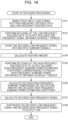
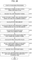
- the encoding device 30 in Fig. 18 performs encoding processing illustrated in the flowchart in Fig. 24 .
- step S301 to step S305 is the same as the processing in step S181 to step S185 in Fig. 19 , and description thereof will be omitted.
- the pseudo high-frequency subband power of each subband has been calculated for every K decoded high-frequency subband power estimating coefficients.
- the pseudo high-frequency subband power difference calculating circuit 36 calculates the following Expression (16) to calculate a residual square mean value Res std (id, J).
- difference between the high-frequency subband power power(ib, J) and pseudo high-frequency subband power power est (ib, id, J) in the frame J is obtained regarding each subband on the high-frequency side of which the index is sb+1 to eb, and sum of squares of the difference thereof is taken as the residual square mean value Res std (id, J).
- the pseudo high-frequency subband power power est (ib, id, J) indicates a pseudo high-frequency subband power in the frame J of a subband of which the index is ib, obtained regarding the decoded high-frequency subband power estimating coefficient of which the coefficient index is id.
- the pseudo high-frequency subband power difference calculating circuit 36 calculates the following Expression (17) to calculate the residual maximum value Res max (id, J).
- Res max id , J max ib power ib , J ⁇ power est ib , id , J
- ⁇ indicates the maximum one of difference absolute values between the high-frequency subband power power(ib, J) of each subband of which the index is sb+1 to eb, and the pseudo high-frequency subband power power est (ib, id, J). Accordingly, the maximum value of the difference absolute values between the high-frequency subband power power(ib, J) and pseudo high-frequency subband power power est (ib, id, J) in the frame J is taken as a residual maximum value Res max (id, J).
- the pseudo high-frequency subband power difference calculating circuit 36 calculates the following Expression (18) to calculate the residual mean value Res ave (id, J).
- the pseudo high-frequency subband power difference calculating circuit 36 performs the above-mentioned processing to calculate the evaluated value Res(id, J) for every K decoded high-frequency subband power estimating coefficients, i.e., for every K coefficient indexes id.
- step S307 the pseudo high-frequency subband power difference calculating circuit 36 selects the coefficient index id based on the evaluated value Res(id, J) for each obtained coefficient index id.
- the evaluated value Res(id, J) obtained in the above-mentioned processing indicates a similarity degree between the high-frequency subband power calculated from the actual high-frequency signal and the pseudo high-frequency subband power calculated using a decoded high-frequency subband power estimating coefficient of which the coefficient index is id, i.e., indicates the magnitude of estimated error of a high-frequency component.
- the pseudo high-frequency subband power difference calculating circuit 36 selects, of the K evaluated values Res(id, J), an evaluated value whereby the value becomes the minimum, and supplies a coefficient index indicating a decoded high-frequency subband power estimating coefficient corresponding to the evaluated value thereof to the high-frequency encoding circuit 37.
- step S308 and step S309 are performed, and the encoding processing is ended, but these processes are the same as step S188 and step S189 in Fig. 19 , and accordingly, description thereof will be omitted.
- the evaluated value Res(id, J) calculated from the residual square mean value Res std (id, J), residual maximum value Res max (id, J), and residual mean value Res ave (id, J) is employed, and a coefficient index of the optimal decoded high-frequency subband power estimating coefficient is selected.
- estimation precision of a high-frequency subband power may be evaluated using many more evaluation scales, and accordingly, a more suitable decoded high-frequency subband power estimating coefficient may be selected.
- a decoded high-frequency subband power estimating coefficient most adapted to the frequency band expanding processing may be obtained, and signals with higher sound quality may be obtained.
- a different coefficient index may be selected for every continuous frames.
- the high-frequency subband powers of the frames are almost the same, and accordingly, the same coefficient index has continuously to be selected with these frames.
- the coefficient index to be selected changes for each frame, and as a result thereof, audio high-frequency components to be played on the decoding device 40 side may not be stationary. Consequently, with audio to be played, unnatural sensations are perceptually caused.
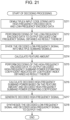
- the encoding device 30 in Fig. 18 performs encoding processing illustrated in the flowchart in Fig. 25 .
- step S331 to step S336 is the same as the processing in step S301 to step S306 in Fig. 24 , and accordingly, description thereof will be omitted.
- step S337 the pseudo high-frequency subband power difference calculating circuit 36 calculates an evaluated value ResP(id, J) using the past frame and the current frame.
- the pseudo high-frequency subband power difference calculating circuit 36 records, regarding the temporally previous frame (J - 1) after the frame J to be processed, a pseudo high-frequency subband power of each subband, obtained by using a decoded high-frequency subband power estimating coefficient having the finally selected coefficient index.
- the finally selected coefficient index mentioned here is a coefficient index encoded by the high-frequency encoding circuit 37 and output to the decoding device 40.
- the coefficient index id selected in the frame (J - 1) is particularly id selected (J - 1).
- a pseudo high-frequency subband power of a subband of which the index is ib (however, sb+1 ⁇ ib ⁇ eb), obtained by using a decoded high-frequency subband power estimating coefficient of the coefficient index id selected (J - 1) is power est (ib, id selected (J - 1), J - 1), description will be continued.
- the pseudo high-frequency subband power difference calculating circuit 36 first calculates the following Expression (20) to calculate an estimated residual square mean value ResP std (id, J).
- the pseudo high-frequency subband power power est (ib, id, J) indicates a pseudo high-frequency subband power of the frame J of a subband of which the index is ib, obtained regarding a decoded high-frequency subband power estimating coefficient of which the coefficient index is id.
- This estimated residual square mean value ResP std (id, J) is difference sum of squares of pseudo high-frequency subband powers between temporally consecutive frames, and accordingly, the smaller the estimated residual square mean value ResP std (id, J) is, the smaller temporal change of an estimated value of a high-frequency component is.
- the pseudo high-frequency subband power difference calculating circuit 36 calculates the following Expression (21) to calculate the estimated residual maximum value ResP max (id, J).
- ResP max id , J max ib power est ib , id selected J ⁇ 1 , J ⁇ 1 ⁇ power est ib , id , J
- ⁇ indicates the maximum one of difference absolute values between the pseudo high-frequency subband power power est (ib, id selected (J - 1), J - 1) of each subband of which the index is sb+1 to eb, and the pseudo high-frequency subband power power est (ib, id, J). Accordingly, the maximum value of the difference absolute values of pseudo high-frequency subband powers between temporally consecutive frames is taken as the estimated residual maximum value ResP max (id, J).
- the estimated residual maximum value ResP max (id, J) indicates that the smaller the value thereof is, the more the estimated results of high-frequency components between consecutive frames approximate.
- the pseudo high-frequency subband power difference calculating circuit 36 calculates the following Expression (22) to calculate the estimated residual mean value ResP ave (id, J).
- difference between the pseudo high-frequency subband power power est (ib, id selected (J - 1), J - 1) of the frame (J - 1) and the pseudo high-frequency subband power est (ib, id, J) of the frame J is obtained.
- the absolute value of a value obtained by dividing the difference sum of the subbands by the number of subbands (eb - sb) on the high-frequency side is taken as the estimated residual mean value ResP ave (id, J).
- This estimated residual mean value ResP ave (id, J) indicates the magnitude of a mean value of estimated difference of the subbands between frames, taking the sign in to consideration.
- the pseudo high-frequency subband power difference calculating circuit 36 calculates the following Expression (23) to calculate an evaluated value ResP(id, J).
- ResP id , J ResP std id , J + W max ⁇ ResP max id , J + W ave ⁇ ResP ave id , J
- the estimated residual square mean value ResP std (id, J), estimated residual maximum value ResP max (id, J), and estimated residual mean value ResP ave (id, J) are added with weight to obtain an evaluated value ResP(id, J).
- step S337 After the evaluated value ResP(id, J) is calculated using the past frame and the current frame, the processing proceeds from step S337 to step S338.
- step S3308 the pseudo high-frequency subband power difference calculating circuit 36 calculates the following Expression (24) to calculate the final evaluated value Res all (id, J).
- Res all id , J Res id , J + W p J ⁇ ResP id , J
- step S340 and step S341 are performed, and the encoding processing is ended, but these processes are the same as step S308 and step S309 in Fig. 24 , and accordingly, description thereof will be omitted.
- weighting is performed for each subband so as to put weight on a subband on a lower frequency side, thereby enabling audio with higher sound quality to be obtained at the decoding device 40 side.
- the human auditory perception has a characteristic to the effect that the greater a frequency band has amplitude (power), the more the human auditory perception senses this, and accordingly, an evaluated value regarding each decoded high-frequency subband power estimating coefficient may be calculated so as to put weight on a subband with greater power.
- the decoding device 30 in Fig. 18 performs encoding processing illustrated in the flowchart in Fig. 27 .
- the encoding processing by the encoding device 30 will be described with reference to the flowchart in Fig. 27 .
- processes in step S401 to step S405 are the same as the processes in step S331 to step S335 in Fig. 25 , and accordingly, description thereof will be omitted.
- step S406 the pseudo high-frequency subband power difference calculating circuit 36 calculates an evaluated value ResW power (id, J) with the current frame J serving as an object to be processed being employed, for every K decoded high-frequency subband power estimating coefficients.
- the pseudo high-frequency subband power difference calculating circuit 36 calculates a residual mean value Res ave W power (id, J).
- step S407 the pseudo high-frequency subband power difference calculating circuit 36 calculates an evaluated value ResPW power (id, J) with the past frame and the current frame being employed.
- the pseudo high-frequency subband power difference calculating circuit 36 calculates an estimated residual maximum value ResP max W power (id, J). Specifically, the maximum value of the absolute value of values obtained by multiplying difference between the pseudo high-frequency subband power power est (ib, id selected (J - 1), J- 1) and the pseudo high-frequency subband power est (ib, id, J) of each subband of which the index is sb+1 to eb by the weight W power (power (ib, J)) is taken as the estimated residual maximum value ResP max W power (id, J).
- the pseudo high-frequency subband power difference calculating circuit 36 calculates an estimated residual mean value ResP ave W power (id, J). Specifically, regarding each subband of which the index is sb+1 to eb, difference between the pseudo high-frequency subband power power est (ib, id selected (J - 1), J- 1) and the pseudo high-frequency subband power est (ib, id, J) is obtained, and is multiplied by the weight W power (power (ib, J)).
- the pseudo high-frequency subband power difference calculating circuit 36 obtains sum of the estimated residual square mean value ResP std W power (id, J), estimated residual maximum value ResP max W power (id, J) multiplied by the weight W max , and estimated residual mean value ResP ave W power (id, J) multiplied by the weight W ave , and takes this as an evaluated value ResPW power (id, J).
- step S408 the pseudo high-frequency subband power difference calculating circuit 36 adds the evaluated value ResW power (id, J) and the evaluated value ResPW power (id, J) multiplied by the weight W p (J) in Expression (25) to calculate the final evaluated value Res all W power (id, J).
- This evaluated value Res all W power (id, J) is calculated for every K decoded high-frequency subband power estimating coefficients.
- step S409 to step S411 are performed, and the encoding processing is ended, but these processes are the same as the processes in step S339 to step S341 in Fig. 25 , and accordingly, description thereof will be omitted.
- step S409 of the K coefficient indexes, a coefficient index whereby the evaluated value Res all W power (id, J) becomes the minimum is selected.
- weighting is performed for each subband so as to put weight on a subband having great power, thereby enabling audio with higher sound quality to be obtained at the decoding device 40 side.
- the set of the coefficient A ib (kb) and coefficient B ib serving as decoded high-frequency subband power estimating coefficients have been recorded in the decoding device 40 in Fig. 20 in a manner correlated with a coefficient index.
- a great region needs to be prepared as a recording region such as memory to record these decoded high-frequency subband power estimating coefficients, or the like.
- a coefficient learning device which obtains decoded high-frequency subband power estimating coefficients by learning is configured as illustrated in Fig. 28 , for example.
- a coefficient learning device 81 is configured of a subband dividing circuit 91, a high-frequency subband power calculating circuit 92, a feature amount calculating circuit 93, and a coefficient estimating circuit 94.
- the broadband supervisory signals are signals in which multiple high-frequency subband components and multiple low-frequency subband components are included.
- the subband dividing circuit 91 is configured of a band pass filter and so forth, divides a supplied broadband supervisory signal into multiple subband signals, and supplied to the high-frequency subband power calculating circuit 92 and feature amount calculating circuit 93. Specifically, the high-frequency subband signal of each subband on the high-frequency side of which the index is sb+1 to eb is supplied to the high-frequency subband power calculating circuit 92, and the low-frequency subband signal of each subband on the low-frequency side of which the index is sb-3 to sb is supplied to the feature amount calculating circuit 93.
- the high-frequency subband power calculating circuit 92 calculates the high-frequency subband power of each high-frequency subband signal supplied from the subband dividing circuit 91 to supply to the coefficient estimating circuit 94.
- the feature amount calculating circuit 93 calculates a low-frequency subband power as a feature amount based on each low-frequency subband signal supplied from the subband dividing circuit 91 to supply to the coefficient estimating circuit 94.
- the coefficient estimating circuit 94 generates a decoded high-frequency subband power estimating coefficient by performing regression analysis using the high-frequency subband power from the high-frequency subband power calculating circuit 92 and the feature amount from the feature amount calculating circuit 93 to output to the decoding device 40.
- step S431 the subband dividing circuit 91 divides each of the supplied multiple broadband supervisory signals into multiple subband signals.
- the subband dividing circuit 91 then supplies the high-frequency subband signal of a subband of which the index is sb+1 to eb to the high-frequency subband power calculating circuit 92, and supplies the low-frequency subband signal of a subband of which the index is sb-3 to sb to the feature amount calculating circuit 93.
- step S433 the feature amount calculating circuit 93 performs the calculation of the above-mentioned Expression (1) on each low-frequency subband signal supplied from the subband dividing circuit 91 to calculate a low-frequency subband power as a feature amount to supply to the coefficient estimating circuit 94.
Landscapes
- Engineering & Computer Science (AREA)
- Physics & Mathematics (AREA)
- Health & Medical Sciences (AREA)
- Signal Processing (AREA)
- Audiology, Speech & Language Pathology (AREA)
- Human Computer Interaction (AREA)
- Computational Linguistics (AREA)
- Acoustics & Sound (AREA)
- Multimedia (AREA)
- Quality & Reliability (AREA)
- Spectroscopy & Molecular Physics (AREA)
- Mathematical Physics (AREA)
- Compression, Expansion, Code Conversion, And Decoders (AREA)
- Compression Or Coding Systems Of Tv Signals (AREA)
Claims (4)
- Audiodecodiervorrichtung (40), umfassend:eine Demultiplexschaltung (41), die konfiguriert ist, um eingegebene codierte Daten in niederfrequente codierte Daten, Koeffizienteninformationen zum Erhalten eines Koeffizientensatzes und Glättungsinformationen bezüglich der Glättung zu demultiplexen;eine Niederfrequenzdecodiervorrichtung (42), die konfiguriert ist, um die niederfrequenzcodierten Daten zu decodieren, um ein Niederfrequenzsignal zu erzeugen;eine Teilband-Teilungsschaltung (43), die konfiguriert ist, um das Niederfrequenzsignal in eine Vielzahl von Teilbändern aufzuteilen, um für jedes der Teilbänder ein Niederfrequenzteilbandsignal zu erzeugen;eine Merkmalsbetragsberechnungsschaltung (44), die konfiguriert ist, um einen Merkmalsbetrag basierend auf der Leistung innerhalb der Niederfrequenzteilbandsignale zu berechnen;eine Glättungsschaltung (151), die konfiguriert ist, um den Merkmalsbetrag einer Glättung basierend auf den Glättungsinformationen zu unterziehen, die eine Anzahl von Zeitrahmen angeben, die für die Glättung des Merkmalsbetrags über die Zeit verwendet werden sollen;eine Erzeugungsschaltung (47), die konfiguriert ist, um ein Hochfrequenzsignal basierend auf dem aus den Koeffizienteninformationen gewonnenen Koeffizientensatz, des geglätteten Merkmalsbetrags und den Niederfrequenzteilbandsignalen zu erzeugen; undeine Synthetisierungsschaltung (48), die konfiguriert ist, um ein Ausgangssignal basierend auf dem Niederfrequenzsignal und dem Hochfrequenzsignal zu synthetisieren und das Ausgangssignal auszugeben.
- Audiodecodierverfahren, umfassend:Demultiplexen (S131) von eingegebenen codierten Daten in niederfrequent codierte Daten, von Koeffizienteninformationen zum Erhalten eines Koeffizientensatzes und von Glättungsinformationen bezüglich der Glättung durch eine Verarbeitungsschaltung;Decodieren (S132) der niederfrequent codierten Daten zum Erzeugen eines Niederfrequenzsignals durch die Verarbeitungsschaltung;Aufteilen (S133) des Niederfrequenzsignals in eine Vielzahl von Teilbändern durch die Verarbeitungsschaltung, um für jedes der Teilbänder ein Niederfrequenzteilbandsignal zu erzeugen;Berechnen (S134) eines Merkmalsbetrags durch die Verarbeitungsschaltung basierend auf der Leistung innerhalb der Niederfrequenzteilbandsignale;Unterziehen des Merkmalsbetrags durch die Verarbeitungsschaltung einer Glättung basierend auf den Glättungsinformationen, die eine Anzahl von Zeitrahmen angeben, die für die Glättung des Merkmalsbetrags im Zeitverlauf verwendet werden sollen;Erzeugen eines Hochfrequenzsignals durch die Verarbeitungsschaltung basierend auf dem aus den Koeffizienteninformationen gewonnenen Koeffizientensatz, des geglätteten Merkmalsbetrags und der Niederfrequenzteilbandsignale; undSynthetisieren (S138) eines Ausgangssignals basierend auf dem Niederfrequenzsignal und dem Hochfrequenzsignal durch die Verarbeitungsschaltung und Ausgeben des Ausgangssignals.
- Computerlesbares Medium, das computerausführbare Anweisungen speichert, die, wenn sie von einem Computer ausgeführt werden, den Computer veranlassen, eine Audioverarbeitung auszuführen, die umfasst:Demultiplexen (S131) der eingegebenen codierten Daten in niederfrequent codierte Daten, Koeffizienteninformationen zum Erhalten eines Koeffizientensatzes und Glättungsinformationen bezüglich der Glättung;Decodieren (S132) der niederfrequent codierten Daten zum Erzeugen eines Niederfrequenzsignals;Aufteilen (S133) des Niederfrequenzsignals in eine Vielzahl von Teilbändern, um für jedes der Teilbänder ein Niederfrequenzteilbandsignal zu erzeugen;Berechnen (S134) eines Merkmalsbetrags basierend auf der Leistung innerhalb der Niederfrequenzteilbandsignale;Unterziehen des Merkmalsbetrags einer Glättung basierend auf den Glättungsinformationen, die eine Anzahl von Zeitrahmen angeben, die für die Glättung des Merkmalsbetrags im Zeitverlauf verwendet werden sollen;Erzeugen eines Hochfrequenzsignals basierend auf dem aus den Koeffizienteninformationen gewonnenen Koeffizientensatz, des geglätteten Merkmalsbetrags und der Niederfrequenzteilbandsignale; undSynthetisieren (S138) eines Ausgangssignals basierend auf dem Niederfrequenzsignal und dem Hochfrequenzsignal und Ausgeben des Ausgangssignals.
- Computerprogramm, umfassend Anweisungen, die, wenn sie durch einen Computer ausgeführt wird, den Computer veranlassen, einen Prozess auszuführen, umfassend:Demultiplexen (S131) der eingegebenen codierten Daten in niederfrequent codierte Daten, Koeffizienteninformationen zum Erhalten eines Koeffizientensatzes und Glättungsinformationen bezüglich der Glättung;Decodieren (S132) der niederfrequent codierten Daten zum Erzeugen eines Niederfrequenzsignals;Aufteilen (S133) des Niederfrequenzsignals in eine Vielzahl von Teilbändern, um für jedes der Teilbänder ein Niederfrequenzteilbandsignal zu erzeugen;Berechnen (S134) eines Merkmalsbetrags basierend auf der Leistung innerhalb der Niederfrequenzteilbandsignale;Unterziehen des Merkmalsbetrags einer Glättung basierend auf den Glättungsinformationen, die eine Anzahl von Zeitrahmen angeben, die für die Glättung des Merkmalsbetrags im Zeitverlauf verwendet werden sollen;Erzeugen eines Hochfrequenzsignals basierend auf dem aus den Koeffizienteninformationen gewonnenen Koeffizientensatz, des geglätteten Merkmalsbetrags und der Niederfrequenzteilbandsignale; undSynthetisieren (S138) eines Ausgangssignals basierend auf dem Niederfrequenzsignal und dem Hochfrequenzsignal und Ausgeben des Ausgangssignals.
Priority Applications (2)
| Application Number | Priority Date | Filing Date | Title |
|---|---|---|---|
| EP25171914.2A EP4567793B1 (de) | 2010-10-15 | 2011-10-05 | Dekodierungsvorrichtung und -verfahren sowie programm |
| EP25172923.2A EP4600954B1 (de) | 2010-10-15 | 2011-10-05 | Decodierungsvorrichtung und -verfahren und programm |
Applications Claiming Priority (4)
| Application Number | Priority Date | Filing Date | Title |
|---|---|---|---|
| JP2010232106A JP5707842B2 (ja) | 2010-10-15 | 2010-10-15 | 符号化装置および方法、復号装置および方法、並びにプログラム |
| EP11832458.1A EP2608199B1 (de) | 2010-10-15 | 2011-10-05 | Kodiervorrichtung und -verfahren, dekodiervorrichtung und -verfahren sowie programm dafür |
| PCT/JP2011/072957 WO2012050023A1 (ja) | 2010-10-15 | 2011-10-05 | 符号化装置および方法、復号装置および方法、並びにプログラム |
| EP19185518.8A EP3579230B1 (de) | 2010-10-15 | 2011-10-05 | Decodierungsvorrichtung und -verfahren sowie programm |
Related Parent Applications (3)
| Application Number | Title | Priority Date | Filing Date |
|---|---|---|---|
| EP19185518.8A Division EP3579230B1 (de) | 2010-10-15 | 2011-10-05 | Decodierungsvorrichtung und -verfahren sowie programm |
| EP19185518.8A Division-Into EP3579230B1 (de) | 2010-10-15 | 2011-10-05 | Decodierungsvorrichtung und -verfahren sowie programm |
| EP11832458.1A Division EP2608199B1 (de) | 2010-10-15 | 2011-10-05 | Kodiervorrichtung und -verfahren, dekodiervorrichtung und -verfahren sowie programm dafür |
Related Child Applications (4)
| Application Number | Title | Priority Date | Filing Date |
|---|---|---|---|
| EP25171914.2A Division EP4567793B1 (de) | 2010-10-15 | 2011-10-05 | Dekodierungsvorrichtung und -verfahren sowie programm |
| EP25171914.2A Division-Into EP4567793B1 (de) | 2010-10-15 | 2011-10-05 | Dekodierungsvorrichtung und -verfahren sowie programm |
| EP25172923.2A Division EP4600954B1 (de) | 2010-10-15 | 2011-10-05 | Decodierungsvorrichtung und -verfahren und programm |
| EP25172923.2A Division-Into EP4600954B1 (de) | 2010-10-15 | 2011-10-05 | Decodierungsvorrichtung und -verfahren und programm |
Publications (2)
| Publication Number | Publication Date |
|---|---|
| EP4220638A1 EP4220638A1 (de) | 2023-08-02 |
| EP4220638B1 true EP4220638B1 (de) | 2025-07-09 |
Family
ID=45938252
Family Applications (5)
| Application Number | Title | Priority Date | Filing Date |
|---|---|---|---|
| EP25172923.2A Active EP4600954B1 (de) | 2010-10-15 | 2011-10-05 | Decodierungsvorrichtung und -verfahren und programm |
| EP25171914.2A Active EP4567793B1 (de) | 2010-10-15 | 2011-10-05 | Dekodierungsvorrichtung und -verfahren sowie programm |
| EP23168017.4A Active EP4220638B1 (de) | 2010-10-15 | 2011-10-05 | Decodierungsvorrichtung und -verfahren und programm |
| EP11832458.1A Active EP2608199B1 (de) | 2010-10-15 | 2011-10-05 | Kodiervorrichtung und -verfahren, dekodiervorrichtung und -verfahren sowie programm dafür |
| EP19185518.8A Active EP3579230B1 (de) | 2010-10-15 | 2011-10-05 | Decodierungsvorrichtung und -verfahren sowie programm |
Family Applications Before (2)
| Application Number | Title | Priority Date | Filing Date |
|---|---|---|---|
| EP25172923.2A Active EP4600954B1 (de) | 2010-10-15 | 2011-10-05 | Decodierungsvorrichtung und -verfahren und programm |
| EP25171914.2A Active EP4567793B1 (de) | 2010-10-15 | 2011-10-05 | Dekodierungsvorrichtung und -verfahren sowie programm |
Family Applications After (2)
| Application Number | Title | Priority Date | Filing Date |
|---|---|---|---|
| EP11832458.1A Active EP2608199B1 (de) | 2010-10-15 | 2011-10-05 | Kodiervorrichtung und -verfahren, dekodiervorrichtung und -verfahren sowie programm dafür |
| EP19185518.8A Active EP3579230B1 (de) | 2010-10-15 | 2011-10-05 | Decodierungsvorrichtung und -verfahren sowie programm |
Country Status (14)
| Country | Link |
|---|---|
| US (4) | US9177563B2 (de) |
| EP (5) | EP4600954B1 (de) |
| JP (1) | JP5707842B2 (de) |
| KR (2) | KR101835910B1 (de) |
| CN (1) | CN103155031B (de) |
| AR (1) | AR083365A1 (de) |
| AU (1) | AU2011314848B2 (de) |
| BR (1) | BR112013008490B1 (de) |
| CA (1) | CA2811085C (de) |
| ES (1) | ES3040832T3 (de) |
| MX (1) | MX2013003952A (de) |
| RU (2) | RU2589293C2 (de) |
| TW (1) | TWI479481B (de) |
| WO (1) | WO2012050023A1 (de) |
Families Citing this family (29)
| Publication number | Priority date | Publication date | Assignee | Title |
|---|---|---|---|---|
| JP5754899B2 (ja) | 2009-10-07 | 2015-07-29 | ソニー株式会社 | 復号装置および方法、並びにプログラム |
| JP5609737B2 (ja) | 2010-04-13 | 2014-10-22 | ソニー株式会社 | 信号処理装置および方法、符号化装置および方法、復号装置および方法、並びにプログラム |
| JP5850216B2 (ja) | 2010-04-13 | 2016-02-03 | ソニー株式会社 | 信号処理装置および方法、符号化装置および方法、復号装置および方法、並びにプログラム |
| JP5652658B2 (ja) | 2010-04-13 | 2015-01-14 | ソニー株式会社 | 信号処理装置および方法、符号化装置および方法、復号装置および方法、並びにプログラム |
| JP6075743B2 (ja) | 2010-08-03 | 2017-02-08 | ソニー株式会社 | 信号処理装置および方法、並びにプログラム |
| JP5707842B2 (ja) | 2010-10-15 | 2015-04-30 | ソニー株式会社 | 符号化装置および方法、復号装置および方法、並びにプログラム |
| JP5743137B2 (ja) | 2011-01-14 | 2015-07-01 | ソニー株式会社 | 信号処理装置および方法、並びにプログラム |
| JP6037156B2 (ja) | 2011-08-24 | 2016-11-30 | ソニー株式会社 | 符号化装置および方法、並びにプログラム |
| JP5942358B2 (ja) | 2011-08-24 | 2016-06-29 | ソニー株式会社 | 符号化装置および方法、復号装置および方法、並びにプログラム |
| JP5975243B2 (ja) * | 2011-08-24 | 2016-08-23 | ソニー株式会社 | 符号化装置および方法、並びにプログラム |
| WO2013183928A1 (ko) * | 2012-06-04 | 2013-12-12 | 삼성전자 주식회사 | 오디오 부호화방법 및 장치, 오디오 복호화방법 및 장치, 및 이를 채용하는 멀티미디어 기기 |
| RU2649944C2 (ru) | 2012-07-02 | 2018-04-05 | Сони Корпорейшн | Устройство декодирования, способ декодирования, устройство кодирования, способ кодирования и программа |
| JP6305694B2 (ja) * | 2013-05-31 | 2018-04-04 | クラリオン株式会社 | 信号処理装置及び信号処理方法 |
| ES2836194T3 (es) * | 2013-06-11 | 2021-06-24 | Fraunhofer Ges Forschung | Dispositivo y procedimiento para la extensión de ancho de banda para señales acústicas |
| CN111292757B (zh) | 2013-09-12 | 2024-05-24 | 杜比国际公司 | 基于qmf的处理数据的时间对齐 |
| KR102159990B1 (ko) | 2013-09-17 | 2020-09-25 | 주식회사 윌러스표준기술연구소 | 멀티미디어 신호 처리 방법 및 장치 |
| JP6531649B2 (ja) | 2013-09-19 | 2019-06-19 | ソニー株式会社 | 符号化装置および方法、復号化装置および方法、並びにプログラム |
| US10580417B2 (en) | 2013-10-22 | 2020-03-03 | Industry-Academic Cooperation Foundation, Yonsei University | Method and apparatus for binaural rendering audio signal using variable order filtering in frequency domain |
| US9524720B2 (en) * | 2013-12-15 | 2016-12-20 | Qualcomm Incorporated | Systems and methods of blind bandwidth extension |
| KR101627657B1 (ko) | 2013-12-23 | 2016-06-07 | 주식회사 윌러스표준기술연구소 | 오디오 신호의 필터 생성 방법 및 이를 위한 파라메터화 장치 |
| KR102356012B1 (ko) | 2013-12-27 | 2022-01-27 | 소니그룹주식회사 | 복호화 장치 및 방법, 및 프로그램 |
| KR101782917B1 (ko) | 2014-03-19 | 2017-09-28 | 주식회사 윌러스표준기술연구소 | 오디오 신호 처리 방법 및 장치 |
| KR101856540B1 (ko) | 2014-04-02 | 2018-05-11 | 주식회사 윌러스표준기술연구소 | 오디오 신호 처리 방법 및 장치 |
| JP2016038435A (ja) * | 2014-08-06 | 2016-03-22 | ソニー株式会社 | 符号化装置および方法、復号装置および方法、並びにプログラム |
| EP3343558A4 (de) * | 2015-09-04 | 2018-07-04 | Samsung Electronics Co., Ltd. | Signalverarbeitungsverfahren und vorrichtungen zur verbesserung der tonqualität |
| EP3818528A1 (de) * | 2018-07-03 | 2021-05-12 | Soclip! | Taktzerlegung zur erleichterung der automatischen videobearbeitung |
| KR20200142787A (ko) | 2019-06-13 | 2020-12-23 | 네이버 주식회사 | 멀티미디어 신호 인식을 위한 전자 장치 및 그의 동작 방법 |
| WO2021261235A1 (ja) * | 2020-06-22 | 2021-12-30 | ソニーグループ株式会社 | 信号処理装置および方法、並びにプログラム |
| JP7809337B2 (ja) * | 2022-09-28 | 2026-02-02 | 株式会社アクセル | エンコーダ、データ処理方法、データ処理プログラム、データ処理システム、及びデコーダ |
Family Cites Families (180)
| Publication number | Priority date | Publication date | Assignee | Title |
|---|---|---|---|---|
| US4628529A (en) | 1985-07-01 | 1986-12-09 | Motorola, Inc. | Noise suppression system |
| JPH03254223A (ja) | 1990-03-02 | 1991-11-13 | Eastman Kodak Japan Kk | アナログデータ伝送方式 |
| JP2655485B2 (ja) | 1994-06-24 | 1997-09-17 | 日本電気株式会社 | 音声セル符号化装置 |
| JP3498375B2 (ja) | 1994-07-20 | 2004-02-16 | ソニー株式会社 | ディジタル・オーディオ信号記録装置 |
| JP3189598B2 (ja) * | 1994-10-28 | 2001-07-16 | 松下電器産業株式会社 | 信号合成方法および信号合成装置 |
| JPH1020888A (ja) | 1996-07-02 | 1998-01-23 | Matsushita Electric Ind Co Ltd | 音声符号化・復号化装置 |
| US6073100A (en) | 1997-03-31 | 2000-06-06 | Goodridge, Jr.; Alan G | Method and apparatus for synthesizing signals using transform-domain match-output extension |
| SE512719C2 (sv) | 1997-06-10 | 2000-05-02 | Lars Gustaf Liljeryd | En metod och anordning för reduktion av dataflöde baserad på harmonisk bandbreddsexpansion |
| WO1999003096A1 (en) | 1997-07-11 | 1999-01-21 | Sony Corporation | Information decoder and decoding method, information encoder and encoding method, and distribution medium |
| SE9903553D0 (sv) * | 1999-01-27 | 1999-10-01 | Lars Liljeryd | Enhancing percepptual performance of SBR and related coding methods by adaptive noise addition (ANA) and noise substitution limiting (NSL) |
| EP1126620B1 (de) | 1999-05-14 | 2005-12-21 | Matsushita Electric Industrial Co., Ltd. | Verfahren und vorrichtung zur banderweiterung eines audiosignals |
| US6978236B1 (en) * | 1999-10-01 | 2005-12-20 | Coding Technologies Ab | Efficient spectral envelope coding using variable time/frequency resolution and time/frequency switching |
| JP3454206B2 (ja) | 1999-11-10 | 2003-10-06 | 三菱電機株式会社 | 雑音抑圧装置及び雑音抑圧方法 |
| CA2290037A1 (en) | 1999-11-18 | 2001-05-18 | Voiceage Corporation | Gain-smoothing amplifier device and method in codecs for wideband speech and audio signals |
| SE0004163D0 (sv) | 2000-11-14 | 2000-11-14 | Coding Technologies Sweden Ab | Enhancing perceptual performance of high frequency reconstruction coding methods by adaptive filtering |
| JP2002268698A (ja) | 2001-03-08 | 2002-09-20 | Nec Corp | 音声認識装置と標準パターン作成装置及び方法並びにプログラム |
| SE0101175D0 (sv) | 2001-04-02 | 2001-04-02 | Coding Technologies Sweden Ab | Aliasing reduction using complex-exponential-modulated filterbanks |
| JP4231987B2 (ja) | 2001-06-15 | 2009-03-04 | 日本電気株式会社 | 音声符号化復号方式間の符号変換方法、その装置、そのプログラム及び記憶媒体 |
| EP1405303A1 (de) | 2001-06-28 | 2004-04-07 | Koninklijke Philips Electronics N.V. | Breitbandsignalübertragungssystem |
| EP1351401B1 (de) | 2001-07-13 | 2009-01-14 | Panasonic Corporation | Audiosignaldecodierungseinrichtung und audiosignalcodierungseinrichtung |
| US6895375B2 (en) | 2001-10-04 | 2005-05-17 | At&T Corp. | System for bandwidth extension of Narrow-band speech |
| US6988066B2 (en) | 2001-10-04 | 2006-01-17 | At&T Corp. | Method of bandwidth extension for narrow-band speech |
| KR100935961B1 (ko) * | 2001-11-14 | 2010-01-08 | 파나소닉 주식회사 | 부호화 장치 및 복호화 장치 |
| JP3926726B2 (ja) * | 2001-11-14 | 2007-06-06 | 松下電器産業株式会社 | 符号化装置および復号化装置 |
| PT1423847E (pt) | 2001-11-29 | 2005-05-31 | Coding Tech Ab | Reconstrucao de componentes de frequencia elevada |
| EP1470550B1 (de) | 2002-01-30 | 2008-09-03 | Matsushita Electric Industrial Co., Ltd. | Verfahren und vorrichtung zur audio-kodierung und -dekodierung |
| JP2003255973A (ja) | 2002-02-28 | 2003-09-10 | Nec Corp | 音声帯域拡張システムおよび方法 |
| US20030187663A1 (en) | 2002-03-28 | 2003-10-02 | Truman Michael Mead | Broadband frequency translation for high frequency regeneration |
| JP2003316394A (ja) | 2002-04-23 | 2003-11-07 | Nec Corp | 音声復号システム、及び、音声復号方法、並びに、音声復号プログラム |
| US7447631B2 (en) | 2002-06-17 | 2008-11-04 | Dolby Laboratories Licensing Corporation | Audio coding system using spectral hole filling |
| US7555434B2 (en) * | 2002-07-19 | 2009-06-30 | Nec Corporation | Audio decoding device, decoding method, and program |
| JP4728568B2 (ja) | 2002-09-04 | 2011-07-20 | マイクロソフト コーポレーション | レベル・モードとラン・レングス/レベル・モードの間での符号化を適応させるエントロピー符号化 |
| JP3881943B2 (ja) | 2002-09-06 | 2007-02-14 | 松下電器産業株式会社 | 音響符号化装置及び音響符号化方法 |
| SE0202770D0 (sv) | 2002-09-18 | 2002-09-18 | Coding Technologies Sweden Ab | Method for reduction of aliasing introduces by spectral envelope adjustment in real-valued filterbanks |
| ES2259158T3 (es) | 2002-09-19 | 2006-09-16 | Matsushita Electric Industrial Co., Ltd. | Metodo y aparato decodificador audio. |
| US7330812B2 (en) | 2002-10-04 | 2008-02-12 | National Research Council Of Canada | Method and apparatus for transmitting an audio stream having additional payload in a hidden sub-channel |
| US7787632B2 (en) | 2003-03-04 | 2010-08-31 | Nokia Corporation | Support of a multichannel audio extension |
| US7318035B2 (en) | 2003-05-08 | 2008-01-08 | Dolby Laboratories Licensing Corporation | Audio coding systems and methods using spectral component coupling and spectral component regeneration |
| US20050004793A1 (en) | 2003-07-03 | 2005-01-06 | Pasi Ojala | Signal adaptation for higher band coding in a codec utilizing band split coding |
| KR20050027179A (ko) | 2003-09-13 | 2005-03-18 | 삼성전자주식회사 | 오디오 데이터 복원 방법 및 그 장치 |
| DE602004032587D1 (de) * | 2003-09-16 | 2011-06-16 | Panasonic Corp | Codierungsvorrichtung und Decodierungsvorrichtung |
| US7844451B2 (en) | 2003-09-16 | 2010-11-30 | Panasonic Corporation | Spectrum coding/decoding apparatus and method for reducing distortion of two band spectrums |
| CN101556800B (zh) | 2003-10-23 | 2012-05-23 | 松下电器产业株式会社 | 音频频谱编解码方法和装置、声音信号发送和接收装置 |
| KR100587953B1 (ko) | 2003-12-26 | 2006-06-08 | 한국전자통신연구원 | 대역-분할 광대역 음성 코덱에서의 고대역 오류 은닉 장치 및 그를 이용한 비트스트림 복호화 시스템 |
| EP3336843B1 (de) | 2004-05-14 | 2021-06-23 | Panasonic Intellectual Property Corporation of America | Sprachcodierungsverfahren und sprachcodierungsvorrichtung |
| WO2005112001A1 (ja) | 2004-05-19 | 2005-11-24 | Matsushita Electric Industrial Co., Ltd. | 符号化装置、復号化装置、およびこれらの方法 |
| ATE474310T1 (de) | 2004-05-28 | 2010-07-15 | Nokia Corp | Mehrkanalige audio-erweiterung |
| KR100608062B1 (ko) | 2004-08-04 | 2006-08-02 | 삼성전자주식회사 | 오디오 데이터의 고주파수 복원 방법 및 그 장치 |
| US7716046B2 (en) | 2004-10-26 | 2010-05-11 | Qnx Software Systems (Wavemakers), Inc. | Advanced periodic signal enhancement |
| US20060106620A1 (en) | 2004-10-28 | 2006-05-18 | Thompson Jeffrey K | Audio spatial environment down-mixer |
| SE0402651D0 (sv) | 2004-11-02 | 2004-11-02 | Coding Tech Ab | Advanced methods for interpolation and parameter signalling |
| JP4977471B2 (ja) | 2004-11-05 | 2012-07-18 | パナソニック株式会社 | 符号化装置及び符号化方法 |
| US7983904B2 (en) | 2004-11-05 | 2011-07-19 | Panasonic Corporation | Scalable decoding apparatus and scalable encoding apparatus |
| KR100657916B1 (ko) | 2004-12-01 | 2006-12-14 | 삼성전자주식회사 | 주파수 대역간의 유사도를 이용한 오디오 신호 처리 장치및 방법 |
| EP1840874B1 (de) * | 2005-01-11 | 2019-04-10 | NEC Corporation | Vorrichtung, verfahren und programm zur audiokodierung |
| KR100707177B1 (ko) * | 2005-01-19 | 2007-04-13 | 삼성전자주식회사 | 디지털 신호 부호화/복호화 방법 및 장치 |
| KR100708121B1 (ko) | 2005-01-22 | 2007-04-16 | 삼성전자주식회사 | 음성 신호의 대역 확장 방법 및 장치 |
| US8260611B2 (en) | 2005-04-01 | 2012-09-04 | Qualcomm Incorporated | Systems, methods, and apparatus for highband excitation generation |
| EP1829424B1 (de) | 2005-04-15 | 2009-01-21 | Dolby Sweden AB | Zeitliche hüllkurvenformgebung von entkorrelierten signalen |
| US20070005351A1 (en) | 2005-06-30 | 2007-01-04 | Sathyendra Harsha M | Method and system for bandwidth expansion for voice communications |
| JP4899359B2 (ja) | 2005-07-11 | 2012-03-21 | ソニー株式会社 | 信号符号化装置及び方法、信号復号装置及び方法、並びにプログラム及び記録媒体 |
| KR100813259B1 (ko) | 2005-07-13 | 2008-03-13 | 삼성전자주식회사 | 입력신호의 계층적 부호화/복호화 장치 및 방법 |
| CN101253556B (zh) | 2005-09-02 | 2011-06-22 | 松下电器产业株式会社 | 能量整形装置以及能量整形方法 |
| EP1926083A4 (de) * | 2005-09-30 | 2011-01-26 | Panasonic Corp | Audiocodierungsgerät und audiocodierungsmethode |
| RU2008114382A (ru) | 2005-10-14 | 2009-10-20 | Панасоник Корпорэйшн (Jp) | Кодер с преобразованием и способ кодирования с преобразованием |
| AU2005337961B2 (en) | 2005-11-04 | 2011-04-21 | Nokia Technologies Oy | Audio compression |
| EP1959433B1 (de) | 2005-11-30 | 2011-10-19 | Panasonic Corporation | Subband-codierungsvorrichtung und verfahren zur subband-codierung |
| JP4876574B2 (ja) | 2005-12-26 | 2012-02-15 | ソニー株式会社 | 信号符号化装置及び方法、信号復号装置及び方法、並びにプログラム及び記録媒体 |
| JP4863713B2 (ja) | 2005-12-29 | 2012-01-25 | 富士通株式会社 | 雑音抑制装置、雑音抑制方法、及びコンピュータプログラム |
| RU2414009C2 (ru) * | 2006-01-18 | 2011-03-10 | ЭлДжи ЭЛЕКТРОНИКС ИНК. | Устройство и способ для кодирования и декодирования сигнала |
| US7953604B2 (en) | 2006-01-20 | 2011-05-31 | Microsoft Corporation | Shape and scale parameters for extended-band frequency coding |
| US7590523B2 (en) | 2006-03-20 | 2009-09-15 | Mindspeed Technologies, Inc. | Speech post-processing using MDCT coefficients |
| JP4976381B2 (ja) | 2006-03-31 | 2012-07-18 | パナソニック株式会社 | 音声符号化装置、音声復号化装置、およびこれらの方法 |
| DE602007013026D1 (de) | 2006-04-27 | 2011-04-21 | Panasonic Corp | Audiocodierungseinrichtung, audiodecodierungseinrichtung und verfahren dafür |
| EP2017830B9 (de) | 2006-05-10 | 2011-02-23 | Panasonic Corporation | Codierungseinrichtung und codierungsverfahren |
| JP2007316254A (ja) | 2006-05-24 | 2007-12-06 | Sony Corp | オーディオ信号補間方法及びオーディオ信号補間装置 |
| KR20070115637A (ko) | 2006-06-03 | 2007-12-06 | 삼성전자주식회사 | 대역폭 확장 부호화 및 복호화 방법 및 장치 |
| JP2007333785A (ja) | 2006-06-12 | 2007-12-27 | Matsushita Electric Ind Co Ltd | オーディオ信号符号化装置およびオーディオ信号符号化方法 |
| WO2007148925A1 (en) | 2006-06-21 | 2007-12-27 | Samsung Electronics Co., Ltd. | Method and apparatus for adaptively encoding and decoding high frequency band |
| KR101244310B1 (ko) | 2006-06-21 | 2013-03-18 | 삼성전자주식회사 | 광대역 부호화 및 복호화 방법 및 장치 |
| US8260609B2 (en) | 2006-07-31 | 2012-09-04 | Qualcomm Incorporated | Systems, methods, and apparatus for wideband encoding and decoding of inactive frames |
| WO2008032828A1 (en) | 2006-09-15 | 2008-03-20 | Panasonic Corporation | Audio encoding device and audio encoding method |
| JP4918841B2 (ja) | 2006-10-23 | 2012-04-18 | 富士通株式会社 | 符号化システム |
| JP5141180B2 (ja) | 2006-11-09 | 2013-02-13 | ソニー株式会社 | 周波数帯域拡大装置及び周波数帯域拡大方法、再生装置及び再生方法、並びに、プログラム及び記録媒体 |
| US8295507B2 (en) | 2006-11-09 | 2012-10-23 | Sony Corporation | Frequency band extending apparatus, frequency band extending method, player apparatus, playing method, program and recording medium |
| KR101565919B1 (ko) | 2006-11-17 | 2015-11-05 | 삼성전자주식회사 | 고주파수 신호 부호화 및 복호화 방법 및 장치 |
| JP4930320B2 (ja) | 2006-11-30 | 2012-05-16 | ソニー株式会社 | 再生方法及び装置、プログラム並びに記録媒体 |
| JP5339919B2 (ja) | 2006-12-15 | 2013-11-13 | パナソニック株式会社 | 符号化装置、復号装置およびこれらの方法 |
| JP4984983B2 (ja) | 2007-03-09 | 2012-07-25 | 富士通株式会社 | 符号化装置および符号化方法 |
| JP2008261978A (ja) | 2007-04-11 | 2008-10-30 | Toshiba Microelectronics Corp | 再生音量自動調整方法 |
| US8015368B2 (en) | 2007-04-20 | 2011-09-06 | Siport, Inc. | Processor extensions for accelerating spectral band replication |
| KR101355376B1 (ko) | 2007-04-30 | 2014-01-23 | 삼성전자주식회사 | 고주파수 영역 부호화 및 복호화 방법 및 장치 |
| JP5434592B2 (ja) | 2007-06-27 | 2014-03-05 | 日本電気株式会社 | オーディオ符号化方法、オーディオ復号方法、オーディオ符号化装置、オーディオ復号装置、プログラム、およびオーディオ符号化・復号システム |
| WO2009004727A1 (ja) * | 2007-07-04 | 2009-01-08 | Fujitsu Limited | 符号化装置、符号化方法および符号化プログラム |
| JP5045295B2 (ja) | 2007-07-30 | 2012-10-10 | ソニー株式会社 | 信号処理装置及び方法、並びにプログラム |
| US8041577B2 (en) | 2007-08-13 | 2011-10-18 | Mitsubishi Electric Research Laboratories, Inc. | Method for expanding audio signal bandwidth |
| CA2697920C (en) | 2007-08-27 | 2018-01-02 | Telefonaktiebolaget L M Ericsson (Publ) | Transient detector and method for supporting encoding of an audio signal |
| DK2186089T3 (en) | 2007-08-27 | 2019-01-07 | Ericsson Telefon Ab L M | Method and apparatus for perceptual spectral decoding of an audio signal including filling in spectral holes |
| DK2571024T3 (en) | 2007-08-27 | 2015-01-05 | Ericsson Telefon Ab L M | Adaptive transition frequency between the noise filling and bandwidth extension |
| US8554349B2 (en) | 2007-10-23 | 2013-10-08 | Clarion Co., Ltd. | High-frequency interpolation device and high-frequency interpolation method |
| JP4733727B2 (ja) | 2007-10-30 | 2011-07-27 | 日本電信電話株式会社 | 音声楽音擬似広帯域化装置と音声楽音擬似広帯域化方法、及びそのプログラムとその記録媒体 |
| KR101373004B1 (ko) | 2007-10-30 | 2014-03-26 | 삼성전자주식회사 | 고주파수 신호 부호화 및 복호화 장치 및 방법 |
| US8352249B2 (en) | 2007-11-01 | 2013-01-08 | Panasonic Corporation | Encoding device, decoding device, and method thereof |
| US20090132238A1 (en) | 2007-11-02 | 2009-05-21 | Sudhakar B | Efficient method for reusing scale factors to improve the efficiency of an audio encoder |
| JP5547081B2 (ja) | 2007-11-02 | 2014-07-09 | 華為技術有限公司 | 音声復号化方法及び装置 |
| EP2220646A1 (de) | 2007-11-06 | 2010-08-25 | Nokia Corporation | Audiocodierungsvorrichtung und verfahren dafür |
| JP2009116275A (ja) | 2007-11-09 | 2009-05-28 | Toshiba Corp | 雑音抑圧、音声スペクトル平滑化、音声特徴抽出、音声認識及び音声モデルトレーニングための方法及び装置 |
| EP2218068A4 (de) | 2007-11-21 | 2010-11-24 | Lg Electronics Inc | Verfahren und vorrichtung zur verarbeitung eines signals |
| US8688441B2 (en) | 2007-11-29 | 2014-04-01 | Motorola Mobility Llc | Method and apparatus to facilitate provision and use of an energy value to determine a spectral envelope shape for out-of-signal bandwidth content |
| US8423371B2 (en) | 2007-12-21 | 2013-04-16 | Panasonic Corporation | Audio encoder, decoder, and encoding method thereof |
| JPWO2009084221A1 (ja) | 2007-12-27 | 2011-05-12 | パナソニック株式会社 | 符号化装置、復号装置およびこれらの方法 |
| ATE518224T1 (de) | 2008-01-04 | 2011-08-15 | Dolby Int Ab | Audiokodierer und -dekodierer |
| US8422569B2 (en) | 2008-01-25 | 2013-04-16 | Panasonic Corporation | Encoding device, decoding device, and method thereof |
| KR101413968B1 (ko) | 2008-01-29 | 2014-07-01 | 삼성전자주식회사 | 오디오 신호의 부호화, 복호화 방법 및 장치 |
| US8433582B2 (en) | 2008-02-01 | 2013-04-30 | Motorola Mobility Llc | Method and apparatus for estimating high-band energy in a bandwidth extension system |
| US20090201983A1 (en) | 2008-02-07 | 2009-08-13 | Motorola, Inc. | Method and apparatus for estimating high-band energy in a bandwidth extension system |
| EP2259253B1 (de) | 2008-03-03 | 2017-11-15 | LG Electronics Inc. | Verfahren und vorrichtung zur verarbeitung von tonsignalen |
| KR101449434B1 (ko) | 2008-03-04 | 2014-10-13 | 삼성전자주식회사 | 복수의 가변장 부호 테이블을 이용한 멀티 채널 오디오를부호화/복호화하는 방법 및 장치 |
| EP2104096B1 (de) | 2008-03-20 | 2020-05-06 | Fraunhofer-Gesellschaft zur Förderung der angewandten Forschung e.V. | Vorrichtung und verfahren zum umwandeln eines audiosignals in eine parametrisierende darstellung, vorrichtung und verfahren zum modifizieren einer parametrisierenden darstellung, vorrichtung und verfahren zur synchronisation eines audiosignals |
| KR20090122142A (ko) | 2008-05-23 | 2009-11-26 | 엘지전자 주식회사 | 오디오 신호 처리 방법 및 장치 |
| US8498344B2 (en) | 2008-06-20 | 2013-07-30 | Rambus Inc. | Frequency responsive bus coding |
| CA2730198C (en) | 2008-07-11 | 2014-09-16 | Frederik Nagel | Audio signal synthesizer and audio signal encoder |
| EP2304719B1 (de) | 2008-07-11 | 2017-07-26 | Fraunhofer-Gesellschaft zur Förderung der angewandten Forschung e.V. | Audiokodierer, verfahren zum bereitstellen eines audiodatenstroms und computerprogramm |
| JP5203077B2 (ja) | 2008-07-14 | 2013-06-05 | 株式会社エヌ・ティ・ティ・ドコモ | 音声符号化装置及び方法、音声復号化装置及び方法、並びに、音声帯域拡張装置及び方法 |
| CN102099855B (zh) | 2008-08-08 | 2012-09-26 | 松下电器产业株式会社 | 频谱平滑化装置、编码装置、解码装置、通信终端装置、基站装置以及频谱平滑化方法 |
| JP2010079275A (ja) * | 2008-08-29 | 2010-04-08 | Sony Corp | 周波数帯域拡大装置及び方法、符号化装置及び方法、復号化装置及び方法、並びにプログラム |
| US8352279B2 (en) | 2008-09-06 | 2013-01-08 | Huawei Technologies Co., Ltd. | Efficient temporal envelope coding approach by prediction between low band signal and high band signal |
| WO2010028292A1 (en) | 2008-09-06 | 2010-03-11 | Huawei Technologies Co., Ltd. | Adaptive frequency prediction |
| WO2010028299A1 (en) | 2008-09-06 | 2010-03-11 | Huawei Technologies Co., Ltd. | Noise-feedback for spectral envelope quantization |
| US8798776B2 (en) | 2008-09-30 | 2014-08-05 | Dolby International Ab | Transcoding of audio metadata |
| GB2466201B (en) | 2008-12-10 | 2012-07-11 | Skype Ltd | Regeneration of wideband speech |
| GB0822537D0 (en) | 2008-12-10 | 2009-01-14 | Skype Ltd | Regeneration of wideband speech |
| CN101770776B (zh) | 2008-12-29 | 2011-06-08 | 华为技术有限公司 | 瞬态信号的编码方法和装置、解码方法和装置及处理系统 |
| ES3023486T3 (en) | 2009-01-16 | 2025-06-02 | Dolby Int Ab | Cross product enhanced harmonic transposition |
| US8457975B2 (en) | 2009-01-28 | 2013-06-04 | Fraunhofer-Gesellschaft Zur Foerderung Der Angewandten Forschung E.V. | Audio decoder, audio encoder, methods for decoding and encoding an audio signal and computer program |
| JP4945586B2 (ja) | 2009-02-02 | 2012-06-06 | 株式会社東芝 | 信号帯域拡張装置 |
| US8463599B2 (en) | 2009-02-04 | 2013-06-11 | Motorola Mobility Llc | Bandwidth extension method and apparatus for a modified discrete cosine transform audio coder |
| KR101661374B1 (ko) | 2009-02-26 | 2016-09-29 | 파나소닉 인텔렉츄얼 프로퍼티 코포레이션 오브 아메리카 | 부호화 장치, 복호 장치 및 이들 방법 |
| JP5564803B2 (ja) | 2009-03-06 | 2014-08-06 | ソニー株式会社 | 音響機器及び音響処理方法 |
| CN101853663B (zh) | 2009-03-30 | 2012-05-23 | 华为技术有限公司 | 比特分配方法、编码装置及解码装置 |
| EP2239732A1 (de) | 2009-04-09 | 2010-10-13 | Fraunhofer-Gesellschaft zur Förderung der Angewandten Forschung e.V. | Vorrichtung und Verfahren zur Erzeugung eines synthetischen Audiosignals und zur Kodierung eines Audiosignals |
| CO6440537A2 (es) | 2009-04-09 | 2012-05-15 | Fraunhofer Ges Forschung | Aparato y metodo para generar una señal de audio de sintesis y para codificar una señal de audio |
| JP5223786B2 (ja) | 2009-06-10 | 2013-06-26 | 富士通株式会社 | 音声帯域拡張装置、音声帯域拡張方法及び音声帯域拡張用コンピュータプログラムならびに電話機 |
| US8515768B2 (en) | 2009-08-31 | 2013-08-20 | Apple Inc. | Enhanced audio decoder |
| JP5754899B2 (ja) | 2009-10-07 | 2015-07-29 | ソニー株式会社 | 復号装置および方法、並びにプログラム |
| JP5928539B2 (ja) | 2009-10-07 | 2016-06-01 | ソニー株式会社 | 符号化装置および方法、並びにプログラム |
| CN102081927B (zh) | 2009-11-27 | 2012-07-18 | 中兴通讯股份有限公司 | 一种可分层音频编码、解码方法及系统 |
| US8600749B2 (en) | 2009-12-08 | 2013-12-03 | At&T Intellectual Property I, L.P. | System and method for training adaptation-specific acoustic models for automatic speech recognition |
| US8447617B2 (en) | 2009-12-21 | 2013-05-21 | Mindspeed Technologies, Inc. | Method and system for speech bandwidth extension |
| KR101423737B1 (ko) | 2010-01-21 | 2014-07-24 | 한국전자통신연구원 | 오디오 신호의 디코딩 방법 및 장치 |
| TWI529703B (zh) | 2010-02-11 | 2016-04-11 | 杜比實驗室特許公司 | 用以非破壞地正常化可攜式裝置中音訊訊號響度之系統及方法 |
| JP5375683B2 (ja) | 2010-03-10 | 2013-12-25 | 富士通株式会社 | 通信装置および電力補正方法 |
| WO2011121782A1 (ja) | 2010-03-31 | 2011-10-06 | 富士通株式会社 | 帯域拡張装置および帯域拡張方法 |
| JP5652658B2 (ja) | 2010-04-13 | 2015-01-14 | ソニー株式会社 | 信号処理装置および方法、符号化装置および方法、復号装置および方法、並びにプログラム |
| JP5609737B2 (ja) | 2010-04-13 | 2014-10-22 | ソニー株式会社 | 信号処理装置および方法、符号化装置および方法、復号装置および方法、並びにプログラム |
| JP5850216B2 (ja) | 2010-04-13 | 2016-02-03 | ソニー株式会社 | 信号処理装置および方法、符号化装置および方法、復号装置および方法、並びにプログラム |
| US8793126B2 (en) | 2010-04-14 | 2014-07-29 | Huawei Technologies Co., Ltd. | Time/frequency two dimension post-processing |
| US8560330B2 (en) | 2010-07-19 | 2013-10-15 | Futurewei Technologies, Inc. | Energy envelope perceptual correction for high band coding |
| US9047875B2 (en) | 2010-07-19 | 2015-06-02 | Futurewei Technologies, Inc. | Spectrum flatness control for bandwidth extension |
| ES2484795T3 (es) | 2010-07-19 | 2014-08-12 | Dolby International Ab | Procesamiento de señales de audio durante la reconstrucción de alta frecuencia |
| JP6075743B2 (ja) | 2010-08-03 | 2017-02-08 | ソニー株式会社 | 信号処理装置および方法、並びにプログラム |
| JP2012058358A (ja) | 2010-09-07 | 2012-03-22 | Sony Corp | 雑音抑圧装置、雑音抑圧方法およびプログラム |
| JP5707842B2 (ja) | 2010-10-15 | 2015-04-30 | ソニー株式会社 | 符号化装置および方法、復号装置および方法、並びにプログラム |
| WO2012052802A1 (en) | 2010-10-18 | 2012-04-26 | Nokia Corporation | An audio encoder/decoder apparatus |
| JP5743137B2 (ja) | 2011-01-14 | 2015-07-01 | ソニー株式会社 | 信号処理装置および方法、並びにプログラム |
| JP5704397B2 (ja) | 2011-03-31 | 2015-04-22 | ソニー株式会社 | 符号化装置および方法、並びにプログラム |
| JP6024077B2 (ja) | 2011-07-01 | 2016-11-09 | ヤマハ株式会社 | 信号送信装置および信号処理装置 |
| JP6037156B2 (ja) | 2011-08-24 | 2016-11-30 | ソニー株式会社 | 符号化装置および方法、並びにプログラム |
| JP5942358B2 (ja) | 2011-08-24 | 2016-06-29 | ソニー株式会社 | 符号化装置および方法、復号装置および方法、並びにプログラム |
| JP5975243B2 (ja) | 2011-08-24 | 2016-08-23 | ソニー株式会社 | 符号化装置および方法、並びにプログラム |
| JP5845760B2 (ja) | 2011-09-15 | 2016-01-20 | ソニー株式会社 | 音声処理装置および方法、並びにプログラム |
| US9319159B2 (en) | 2011-09-29 | 2016-04-19 | Dolby International Ab | High quality detection in FM stereo radio signal |
| US20150088528A1 (en) | 2012-04-13 | 2015-03-26 | Sony Corporation | Decoding apparatus and method, audio signal processing apparatus and method, and program |
| JP5997592B2 (ja) | 2012-04-27 | 2016-09-28 | 株式会社Nttドコモ | 音声復号装置 |
| RU2652468C2 (ru) | 2012-07-02 | 2018-04-26 | Сони Корпорейшн | Декодирующее устройство, способ декодирования, кодирующее устройство, способ кодирования и программа |
| RU2649944C2 (ru) | 2012-07-02 | 2018-04-05 | Сони Корпорейшн | Устройство декодирования, способ декодирования, устройство кодирования, способ кодирования и программа |
| TWI517142B (zh) | 2012-07-02 | 2016-01-11 | Sony Corp | Audio decoding apparatus and method, audio coding apparatus and method, and program |
| US9437198B2 (en) | 2012-07-02 | 2016-09-06 | Sony Corporation | Decoding device, decoding method, encoding device, encoding method, and program |
| JP2014123011A (ja) | 2012-12-21 | 2014-07-03 | Sony Corp | 雑音検出装置および方法、並びに、プログラム |
| JP6531649B2 (ja) | 2013-09-19 | 2019-06-19 | ソニー株式会社 | 符号化装置および方法、復号化装置および方法、並びにプログラム |
-
2010
- 2010-10-15 JP JP2010232106A patent/JP5707842B2/ja active Active
-
2011
- 2011-10-05 KR KR1020137008804A patent/KR101835910B1/ko active Active
- 2011-10-05 EP EP25172923.2A patent/EP4600954B1/de active Active
- 2011-10-05 KR KR1020187005834A patent/KR101979557B1/ko active Active
- 2011-10-05 RU RU2013115770/08A patent/RU2589293C2/ru active
- 2011-10-05 BR BR112013008490-1A patent/BR112013008490B1/pt active IP Right Grant
- 2011-10-05 CN CN201180048799.6A patent/CN103155031B/zh active Active
- 2011-10-05 EP EP25171914.2A patent/EP4567793B1/de active Active
- 2011-10-05 CA CA2811085A patent/CA2811085C/en active Active
- 2011-10-05 EP EP23168017.4A patent/EP4220638B1/de active Active
- 2011-10-05 EP EP11832458.1A patent/EP2608199B1/de active Active
- 2011-10-05 EP EP19185518.8A patent/EP3579230B1/de active Active
- 2011-10-05 ES ES23168017T patent/ES3040832T3/es active Active
- 2011-10-05 US US13/877,192 patent/US9177563B2/en active Active
- 2011-10-05 WO PCT/JP2011/072957 patent/WO2012050023A1/ja not_active Ceased
- 2011-10-05 RU RU2016118358A patent/RU2630384C1/ru active
- 2011-10-05 MX MX2013003952A patent/MX2013003952A/es active IP Right Grant
- 2011-10-05 AU AU2011314848A patent/AU2011314848B2/en active Active
- 2011-10-06 TW TW100136316A patent/TWI479481B/zh active
- 2011-10-11 AR ARP110103732A patent/AR083365A1/es active IP Right Grant
-
2015
- 2015-09-22 US US14/861,734 patent/US9536542B2/en active Active
-
2016
- 2016-11-21 US US15/357,877 patent/US9767824B2/en active Active
-
2017
- 2017-08-23 US US15/684,340 patent/US10236015B2/en active Active
Also Published As
Similar Documents
| Publication | Publication Date | Title |
|---|---|---|
| EP4220638B1 (de) | Decodierungsvorrichtung und -verfahren und programm | |
| EP3968322B1 (de) | Decodierungsvorrichtung und -verfahren und programm | |
| JP6508551B2 (ja) | 復号装置および方法、並びにプログラム |
Legal Events
| Date | Code | Title | Description |
|---|---|---|---|
| PUAI | Public reference made under article 153(3) epc to a published international application that has entered the european phase |
Free format text: ORIGINAL CODE: 0009012 |
|
| STAA | Information on the status of an ep patent application or granted ep patent |
Free format text: STATUS: REQUEST FOR EXAMINATION WAS MADE |
|
| 17P | Request for examination filed |
Effective date: 20230429 |
|
| AC | Divisional application: reference to earlier application |
Ref document number: 2608199 Country of ref document: EP Kind code of ref document: P Ref document number: 3579230 Country of ref document: EP Kind code of ref document: P |
|
| AK | Designated contracting states |
Kind code of ref document: A1 Designated state(s): AL AT BE BG CH CY CZ DE DK EE ES FI FR GB GR HR HU IE IS IT LI LT LU LV MC MK MT NL NO PL PT RO RS SE SI SK SM TR |
|
| STAA | Information on the status of an ep patent application or granted ep patent |
Free format text: STATUS: EXAMINATION IS IN PROGRESS |
|
| GRAP | Despatch of communication of intention to grant a patent |
Free format text: ORIGINAL CODE: EPIDOSNIGR1 |
|
| STAA | Information on the status of an ep patent application or granted ep patent |
Free format text: STATUS: GRANT OF PATENT IS INTENDED |
|
| 17Q | First examination report despatched |
Effective date: 20250121 |
|
| RIC1 | Information provided on ipc code assigned before grant |
Ipc: G10L 19/02 20130101ALN20250129BHEP Ipc: G10L 25/21 20130101ALI20250129BHEP Ipc: G10L 25/18 20130101ALI20250129BHEP Ipc: G10L 21/0388 20130101AFI20250129BHEP |
|
| INTG | Intention to grant announced |
Effective date: 20250214 |
|
| P01 | Opt-out of the competence of the unified patent court (upc) registered |
Free format text: CASE NUMBER: APP_18564/2025 Effective date: 20250416 |
|
| GRAS | Grant fee paid |
Free format text: ORIGINAL CODE: EPIDOSNIGR3 |
|
| GRAA | (expected) grant |
Free format text: ORIGINAL CODE: 0009210 |
|
| STAA | Information on the status of an ep patent application or granted ep patent |
Free format text: STATUS: THE PATENT HAS BEEN GRANTED |
|
| AC | Divisional application: reference to earlier application |
Ref document number: 2608199 Country of ref document: EP Kind code of ref document: P Ref document number: 3579230 Country of ref document: EP Kind code of ref document: P |
|
| AK | Designated contracting states |
Kind code of ref document: B1 Designated state(s): AL AT BE BG CH CY CZ DE DK EE ES FI FR GB GR HR HU IE IS IT LI LT LU LV MC MK MT NL NO PL PT RO RS SE SI SK SM TR |
|
| REG | Reference to a national code |
Ref country code: GB Ref legal event code: FG4D |
|
| REG | Reference to a national code |
Ref country code: CH Ref legal event code: EP |
|
| REG | Reference to a national code |
Ref country code: IE Ref legal event code: FG4D |
|
| REG | Reference to a national code |
Ref country code: DE Ref legal event code: R096 Ref document number: 602011075399 Country of ref document: DE |
|
| PGFP | Annual fee paid to national office [announced via postgrant information from national office to epo] |
Ref country code: IT Payment date: 20250923 Year of fee payment: 15 |
|
| PGFP | Annual fee paid to national office [announced via postgrant information from national office to epo] |
Ref country code: GB Payment date: 20250923 Year of fee payment: 15 |
|
| PGFP | Annual fee paid to national office [announced via postgrant information from national office to epo] |
Ref country code: FR Payment date: 20250923 Year of fee payment: 15 |
|
| REG | Reference to a national code |
Ref country code: ES Ref legal event code: FG2A Ref document number: 3040832 Country of ref document: ES Kind code of ref document: T3 Effective date: 20251105 |
|
| REG | Reference to a national code |
Ref country code: NL Ref legal event code: MP Effective date: 20250709 |
|
| PG25 | Lapsed in a contracting state [announced via postgrant information from national office to epo] |
Ref country code: PT Free format text: LAPSE BECAUSE OF FAILURE TO SUBMIT A TRANSLATION OF THE DESCRIPTION OR TO PAY THE FEE WITHIN THE PRESCRIBED TIME-LIMIT Effective date: 20251110 |
|
| PG25 | Lapsed in a contracting state [announced via postgrant information from national office to epo] |
Ref country code: NL Free format text: LAPSE BECAUSE OF FAILURE TO SUBMIT A TRANSLATION OF THE DESCRIPTION OR TO PAY THE FEE WITHIN THE PRESCRIBED TIME-LIMIT Effective date: 20250709 |
|
| REG | Reference to a national code |
Ref country code: AT Ref legal event code: MK05 Ref document number: 1812662 Country of ref document: AT Kind code of ref document: T Effective date: 20250709 |
|
| PG25 | Lapsed in a contracting state [announced via postgrant information from national office to epo] |
Ref country code: IS Free format text: LAPSE BECAUSE OF FAILURE TO SUBMIT A TRANSLATION OF THE DESCRIPTION OR TO PAY THE FEE WITHIN THE PRESCRIBED TIME-LIMIT Effective date: 20251109 |
|
| PGFP | Annual fee paid to national office [announced via postgrant information from national office to epo] |
Ref country code: DE Payment date: 20250923 Year of fee payment: 15 |
|
| PG25 | Lapsed in a contracting state [announced via postgrant information from national office to epo] |
Ref country code: NO Free format text: LAPSE BECAUSE OF FAILURE TO SUBMIT A TRANSLATION OF THE DESCRIPTION OR TO PAY THE FEE WITHIN THE PRESCRIBED TIME-LIMIT Effective date: 20251009 |
|
| REG | Reference to a national code |
Ref country code: LT Ref legal event code: MG9D |
|
| PG25 | Lapsed in a contracting state [announced via postgrant information from national office to epo] |
Ref country code: AT Free format text: LAPSE BECAUSE OF FAILURE TO SUBMIT A TRANSLATION OF THE DESCRIPTION OR TO PAY THE FEE WITHIN THE PRESCRIBED TIME-LIMIT Effective date: 20250709 |
|
| PG25 | Lapsed in a contracting state [announced via postgrant information from national office to epo] |
Ref country code: FI Free format text: LAPSE BECAUSE OF FAILURE TO SUBMIT A TRANSLATION OF THE DESCRIPTION OR TO PAY THE FEE WITHIN THE PRESCRIBED TIME-LIMIT Effective date: 20250709 |
|
| PG25 | Lapsed in a contracting state [announced via postgrant information from national office to epo] |
Ref country code: HR Free format text: LAPSE BECAUSE OF FAILURE TO SUBMIT A TRANSLATION OF THE DESCRIPTION OR TO PAY THE FEE WITHIN THE PRESCRIBED TIME-LIMIT Effective date: 20250709 |
|
| PG25 | Lapsed in a contracting state [announced via postgrant information from national office to epo] |
Ref country code: GR Free format text: LAPSE BECAUSE OF FAILURE TO SUBMIT A TRANSLATION OF THE DESCRIPTION OR TO PAY THE FEE WITHIN THE PRESCRIBED TIME-LIMIT Effective date: 20251010 |
|
| PG25 | Lapsed in a contracting state [announced via postgrant information from national office to epo] |
Ref country code: SE Free format text: LAPSE BECAUSE OF FAILURE TO SUBMIT A TRANSLATION OF THE DESCRIPTION OR TO PAY THE FEE WITHIN THE PRESCRIBED TIME-LIMIT Effective date: 20250709 |
|
| PG25 | Lapsed in a contracting state [announced via postgrant information from national office to epo] |
Ref country code: LV Free format text: LAPSE BECAUSE OF FAILURE TO SUBMIT A TRANSLATION OF THE DESCRIPTION OR TO PAY THE FEE WITHIN THE PRESCRIBED TIME-LIMIT Effective date: 20250709 |
|
| PG25 | Lapsed in a contracting state [announced via postgrant information from national office to epo] |
Ref country code: BG Free format text: LAPSE BECAUSE OF FAILURE TO SUBMIT A TRANSLATION OF THE DESCRIPTION OR TO PAY THE FEE WITHIN THE PRESCRIBED TIME-LIMIT Effective date: 20250709 Ref country code: PL Free format text: LAPSE BECAUSE OF FAILURE TO SUBMIT A TRANSLATION OF THE DESCRIPTION OR TO PAY THE FEE WITHIN THE PRESCRIBED TIME-LIMIT Effective date: 20250709 |
|
| PG25 | Lapsed in a contracting state [announced via postgrant information from national office to epo] |
Ref country code: RS Free format text: LAPSE BECAUSE OF FAILURE TO SUBMIT A TRANSLATION OF THE DESCRIPTION OR TO PAY THE FEE WITHIN THE PRESCRIBED TIME-LIMIT Effective date: 20251009 |
|
| PGFP | Annual fee paid to national office [announced via postgrant information from national office to epo] |
Ref country code: ES Payment date: 20251103 Year of fee payment: 15 |
|
| PG25 | Lapsed in a contracting state [announced via postgrant information from national office to epo] |
Ref country code: RO Free format text: LAPSE BECAUSE OF FAILURE TO SUBMIT A TRANSLATION OF THE DESCRIPTION OR TO PAY THE FEE WITHIN THE PRESCRIBED TIME-LIMIT Effective date: 20250709 |
|
| PG25 | Lapsed in a contracting state [announced via postgrant information from national office to epo] |
Ref country code: SM Free format text: LAPSE BECAUSE OF FAILURE TO SUBMIT A TRANSLATION OF THE DESCRIPTION OR TO PAY THE FEE WITHIN THE PRESCRIBED TIME-LIMIT Effective date: 20250709 |
|
| PG25 | Lapsed in a contracting state [announced via postgrant information from national office to epo] |
Ref country code: DK Free format text: LAPSE BECAUSE OF FAILURE TO SUBMIT A TRANSLATION OF THE DESCRIPTION OR TO PAY THE FEE WITHIN THE PRESCRIBED TIME-LIMIT Effective date: 20250709 |
|
| PG25 | Lapsed in a contracting state [announced via postgrant information from national office to epo] |
Ref country code: CZ Free format text: LAPSE BECAUSE OF FAILURE TO SUBMIT A TRANSLATION OF THE DESCRIPTION OR TO PAY THE FEE WITHIN THE PRESCRIBED TIME-LIMIT Effective date: 20250709 |
|
| PG25 | Lapsed in a contracting state [announced via postgrant information from national office to epo] |
Ref country code: SK Free format text: LAPSE BECAUSE OF FAILURE TO SUBMIT A TRANSLATION OF THE DESCRIPTION OR TO PAY THE FEE WITHIN THE PRESCRIBED TIME-LIMIT Effective date: 20250709 Ref country code: EE Free format text: LAPSE BECAUSE OF FAILURE TO SUBMIT A TRANSLATION OF THE DESCRIPTION OR TO PAY THE FEE WITHIN THE PRESCRIBED TIME-LIMIT Effective date: 20250709 |