EP4220788B1 - Batteriezelle, batterie und elektrische vorrichtung - Google Patents
Batteriezelle, batterie und elektrische vorrichtung Download PDFInfo
- Publication number
- EP4220788B1 EP4220788B1 EP21810262.2A EP21810262A EP4220788B1 EP 4220788 B1 EP4220788 B1 EP 4220788B1 EP 21810262 A EP21810262 A EP 21810262A EP 4220788 B1 EP4220788 B1 EP 4220788B1
- Authority
- EP
- European Patent Office
- Prior art keywords
- concave portion
- electrode assembly
- end cover
- electrode
- battery cell
- Prior art date
- Legal status (The legal status is an assumption and is not a legal conclusion. Google has not performed a legal analysis and makes no representation as to the accuracy of the status listed.)
- Active
Links
Images


Classifications
-
- H—ELECTRICITY
- H01—ELECTRIC ELEMENTS
- H01M—PROCESSES OR MEANS, e.g. BATTERIES, FOR THE DIRECT CONVERSION OF CHEMICAL ENERGY INTO ELECTRICAL ENERGY
- H01M50/00—Constructional details or processes of manufacture of the non-active parts of electrochemical cells other than fuel cells, e.g. hybrid cells
- H01M50/10—Primary casings; Jackets or wrappings
- H01M50/102—Primary casings; Jackets or wrappings characterised by their shape or physical structure
- H01M50/103—Primary casings; Jackets or wrappings characterised by their shape or physical structure prismatic or rectangular
-
- H—ELECTRICITY
- H01—ELECTRIC ELEMENTS
- H01M—PROCESSES OR MEANS, e.g. BATTERIES, FOR THE DIRECT CONVERSION OF CHEMICAL ENERGY INTO ELECTRICAL ENERGY
- H01M50/00—Constructional details or processes of manufacture of the non-active parts of electrochemical cells other than fuel cells, e.g. hybrid cells
- H01M50/10—Primary casings; Jackets or wrappings
- H01M50/102—Primary casings; Jackets or wrappings characterised by their shape or physical structure
- H01M50/107—Primary casings; Jackets or wrappings characterised by their shape or physical structure having curved cross-section, e.g. round or elliptic
-
- H—ELECTRICITY
- H01—ELECTRIC ELEMENTS
- H01M—PROCESSES OR MEANS, e.g. BATTERIES, FOR THE DIRECT CONVERSION OF CHEMICAL ENERGY INTO ELECTRICAL ENERGY
- H01M50/00—Constructional details or processes of manufacture of the non-active parts of electrochemical cells other than fuel cells, e.g. hybrid cells
- H01M50/10—Primary casings; Jackets or wrappings
- H01M50/147—Lids or covers
- H01M50/148—Lids or covers characterised by their shape
- H01M50/15—Lids or covers characterised by their shape for prismatic or rectangular cells
-
- H—ELECTRICITY
- H01—ELECTRIC ELEMENTS
- H01M—PROCESSES OR MEANS, e.g. BATTERIES, FOR THE DIRECT CONVERSION OF CHEMICAL ENERGY INTO ELECTRICAL ENERGY
- H01M50/00—Constructional details or processes of manufacture of the non-active parts of electrochemical cells other than fuel cells, e.g. hybrid cells
- H01M50/20—Mountings; Secondary casings or frames; Racks, modules or packs; Suspension devices; Shock absorbers; Transport or carrying devices; Holders
- H01M50/204—Racks, modules or packs for multiple batteries or multiple cells
- H01M50/207—Racks, modules or packs for multiple batteries or multiple cells characterised by their shape
- H01M50/209—Racks, modules or packs for multiple batteries or multiple cells characterised by their shape adapted for prismatic or rectangular cells
-
- H—ELECTRICITY
- H01—ELECTRIC ELEMENTS
- H01M—PROCESSES OR MEANS, e.g. BATTERIES, FOR THE DIRECT CONVERSION OF CHEMICAL ENERGY INTO ELECTRICAL ENERGY
- H01M50/00—Constructional details or processes of manufacture of the non-active parts of electrochemical cells other than fuel cells, e.g. hybrid cells
- H01M50/20—Mountings; Secondary casings or frames; Racks, modules or packs; Suspension devices; Shock absorbers; Transport or carrying devices; Holders
- H01M50/271—Lids or covers for the racks or secondary casings
-
- H—ELECTRICITY
- H01—ELECTRIC ELEMENTS
- H01M—PROCESSES OR MEANS, e.g. BATTERIES, FOR THE DIRECT CONVERSION OF CHEMICAL ENERGY INTO ELECTRICAL ENERGY
- H01M50/00—Constructional details or processes of manufacture of the non-active parts of electrochemical cells other than fuel cells, e.g. hybrid cells
- H01M50/50—Current conducting connections for cells or batteries
- H01M50/502—Interconnectors for connecting terminals of adjacent batteries; Interconnectors for connecting cells outside a battery casing
- H01M50/505—Interconnectors for connecting terminals of adjacent batteries; Interconnectors for connecting cells outside a battery casing comprising a single busbar
-
- H—ELECTRICITY
- H01—ELECTRIC ELEMENTS
- H01M—PROCESSES OR MEANS, e.g. BATTERIES, FOR THE DIRECT CONVERSION OF CHEMICAL ENERGY INTO ELECTRICAL ENERGY
- H01M50/00—Constructional details or processes of manufacture of the non-active parts of electrochemical cells other than fuel cells, e.g. hybrid cells
- H01M50/50—Current conducting connections for cells or batteries
- H01M50/531—Electrode connections inside a battery casing
- H01M50/533—Electrode connections inside a battery casing characterised by the shape of the leads or tabs
-
- H—ELECTRICITY
- H01—ELECTRIC ELEMENTS
- H01M—PROCESSES OR MEANS, e.g. BATTERIES, FOR THE DIRECT CONVERSION OF CHEMICAL ENERGY INTO ELECTRICAL ENERGY
- H01M50/00—Constructional details or processes of manufacture of the non-active parts of electrochemical cells other than fuel cells, e.g. hybrid cells
- H01M50/50—Current conducting connections for cells or batteries
- H01M50/543—Terminals
- H01M50/547—Terminals characterised by the disposition of the terminals on the cells
- H01M50/55—Terminals characterised by the disposition of the terminals on the cells on the same side of the cell
-
- H—ELECTRICITY
- H01—ELECTRIC ELEMENTS
- H01M—PROCESSES OR MEANS, e.g. BATTERIES, FOR THE DIRECT CONVERSION OF CHEMICAL ENERGY INTO ELECTRICAL ENERGY
- H01M50/00—Constructional details or processes of manufacture of the non-active parts of electrochemical cells other than fuel cells, e.g. hybrid cells
- H01M50/50—Current conducting connections for cells or batteries
- H01M50/572—Means for preventing undesired use or discharge
- H01M50/584—Means for preventing undesired use or discharge for preventing incorrect connections inside or outside the batteries
- H01M50/586—Means for preventing undesired use or discharge for preventing incorrect connections inside or outside the batteries inside the batteries, e.g. incorrect connections of electrodes
-
- H—ELECTRICITY
- H01—ELECTRIC ELEMENTS
- H01M—PROCESSES OR MEANS, e.g. BATTERIES, FOR THE DIRECT CONVERSION OF CHEMICAL ENERGY INTO ELECTRICAL ENERGY
- H01M50/00—Constructional details or processes of manufacture of the non-active parts of electrochemical cells other than fuel cells, e.g. hybrid cells
- H01M50/50—Current conducting connections for cells or batteries
- H01M50/572—Means for preventing undesired use or discharge
- H01M50/584—Means for preventing undesired use or discharge for preventing incorrect connections inside or outside the batteries
- H01M50/59—Means for preventing undesired use or discharge for preventing incorrect connections inside or outside the batteries characterised by the protection means
- H01M50/593—Spacers; Insulating plates
-
- H—ELECTRICITY
- H01—ELECTRIC ELEMENTS
- H01M—PROCESSES OR MEANS, e.g. BATTERIES, FOR THE DIRECT CONVERSION OF CHEMICAL ENERGY INTO ELECTRICAL ENERGY
- H01M10/00—Secondary cells; Manufacture thereof
- H01M10/05—Accumulators with non-aqueous electrolyte
- H01M10/052—Li-accumulators
-
- H—ELECTRICITY
- H01—ELECTRIC ELEMENTS
- H01M—PROCESSES OR MEANS, e.g. BATTERIES, FOR THE DIRECT CONVERSION OF CHEMICAL ENERGY INTO ELECTRICAL ENERGY
- H01M2220/00—Batteries for particular applications
- H01M2220/20—Batteries in motive systems, e.g. vehicle, ship, plane
-
- H—ELECTRICITY
- H01—ELECTRIC ELEMENTS
- H01M—PROCESSES OR MEANS, e.g. BATTERIES, FOR THE DIRECT CONVERSION OF CHEMICAL ENERGY INTO ELECTRICAL ENERGY
- H01M2220/00—Batteries for particular applications
- H01M2220/30—Batteries in portable systems, e.g. mobile phone, laptop
-
- H—ELECTRICITY
- H01—ELECTRIC ELEMENTS
- H01M—PROCESSES OR MEANS, e.g. BATTERIES, FOR THE DIRECT CONVERSION OF CHEMICAL ENERGY INTO ELECTRICAL ENERGY
- H01M50/00—Constructional details or processes of manufacture of the non-active parts of electrochemical cells other than fuel cells, e.g. hybrid cells
- H01M50/50—Current conducting connections for cells or batteries
- H01M50/543—Terminals
- H01M50/552—Terminals characterised by their shape
- H01M50/553—Terminals adapted for prismatic, pouch or rectangular cells
-
- Y—GENERAL TAGGING OF NEW TECHNOLOGICAL DEVELOPMENTS; GENERAL TAGGING OF CROSS-SECTIONAL TECHNOLOGIES SPANNING OVER SEVERAL SECTIONS OF THE IPC; TECHNICAL SUBJECTS COVERED BY FORMER USPC CROSS-REFERENCE ART COLLECTIONS [XRACs] AND DIGESTS
- Y02—TECHNOLOGIES OR APPLICATIONS FOR MITIGATION OR ADAPTATION AGAINST CLIMATE CHANGE
- Y02E—REDUCTION OF GREENHOUSE GAS [GHG] EMISSIONS, RELATED TO ENERGY GENERATION, TRANSMISSION OR DISTRIBUTION
- Y02E60/00—Enabling technologies; Technologies with a potential or indirect contribution to GHG emissions mitigation
- Y02E60/10—Energy storage using batteries
Definitions
- the present application relates to the technical field of batteries, and in particular, to a battery cell, a battery, and a power consumption device, and a manufacturing device and method for the battery cell.
- lithium-ion batteries As a rechargeable battery, lithium-ion batteries have the advantages of small size, high energy density, high power density, multiple recycle times, and long storage time.
- the rechargeable battery includes a housing, an end cover assembly and an electrode assembly.
- the electrode assembly is located in the housing, and the end cover assembly covers at the housing, so as to provide a sealed environment for the electrode assembly.
- the capacity of the battery cell is limited by the structure of the end cover assembly, which in turn affects the capacity of the battery cell.
- CN211629211U discloses a secondary battery, including an electrode assembly, a housing, a top cover assembly and a current collecting member.
- the top cover assembly includes a top cover, an electrode terminal, an insulating partition, and an explosion plate.
- the current collecting member includes a terminal connection part, a tab connection part and a tilting part.
- the insulating partition has a first concave part, which is concave in a direction away from the main body and can accommodate at least part of the tab connection part of the current collecting member.
- Embodiments of the present application provide a battery cell, a battery, a power consumption device, and a manufacturing device and method for a battery cell, which can effectively improve the capacity of the battery cell.
- a first aspect of the embodiments of the present application provides a battery cell, as specified in the claims, including: a housing, with an opening; an electrode assembly, being accommodated in the housing, the electrode assembly including a tab; an end cover assembly, including an end cover, an electrode terminal and an insulating member, the end cover being used to cover at the opening, the electrode terminal being mounted to the end cover, the insulating member located on one side of the end cover facing the electrode assembly; and a current collecting member, for connecting the electrode terminal and the tab, so that the tab is electrically connected to the electrode terminal; where a first concave portion is formed on one side of the insulating member facing the electrode assembly, and the first concave portion is configured to accommodate at least a part of the tab and/or at least a part of the current collecting member, a first convex portion is formed on one side of the insulating member facing away from the electrode assembly at a position corresponding to the first concave portion, a second concave portion is formed on the side of the end cover facing the electrode
- the first concave portion is formed on the side of the insulating member facing the electrode assembly, and the first concave portion can accommodate at least a part of the tab and/or at least a part of the current collecting member, which can make more space for the electrode assembly.
- the first convex portion is formed on the side of the insulating member facing away from the electrode assembly at the position corresponding to the first concave portion.
- the first convex portion can act as a reinforcement at the position where the first concave portion is provided on the insulating member, on the other hand, the arrangement of the first convex portion can make the first concave portion be recessed as much as possible in the direction facing away from the electrode assembly, so as to increase the recess depth of the first concave portion.
- the second concave portion is formed on the side of the end cover facing the electrode assembly, and the first convex portion is accommodated in the second concave portion, which reduces the space inside the housing occupied by the insulating member, and further makes more space for the electrode assembly, thereby effectively increasing the capacity of battery cell.
- the end cover includes the first body for covering the opening of the housing, and the second concave portion is recessed outwards from the first inner surface of the first body.
- the end cover of this structure has a simple structure and is easy to be molded and manufactured.
- the first outer surface of the first body is provided with the second convex portion at the position corresponding to the second concave portion, the second convex portion can strengthen the position where the second concave portion is provided on the first body, which improve the firmness of the end cover.
- the first end surface of the second convex portion does not exceed the electrode terminal in the direction facing away from the electrode assembly, and the second convex portion reasonably utilizes the space between the first outer surface of the first body and an end portion of the electrode terminal.
- the second concave portion has a first bottom wall, the second concave portion is recessed to the first bottom wall from the first inner surface along the direction facing away from the electrode assembly, and the first bottom wall exceeds the first outer surface along the direction facing away from the electrode assembly.
- the first bottom wall of the second concave portion exceeds the first outer surface along the direction facing away from the electrode assembly, so that the second concave portion is recessed to the second convex portion, thereby increasing the recess depth of the second concave portion and increasing the space of the second concave portion for accommodating the first convex portion, so that the first convex portion can extend to a deeper position of the second concave portion.
- the insulating member includes a second body and the first convex portion; the second body has a second inner surface and a second outer surface opposite to each other, the second inner surface faces the electrode assembly, the first concave portion is recessed from the second inner surface along the direction facing away from the electrode assembly, and the first convex portion is protrudingly provided on the second outer surface.
- the first convex portion is protrudingly provided on the second outer surface of the second body, and the first concave portion is recessed from the second inner surface of the second body along the direction facing away from the electrode assembly.
- the insulating member of this structure has a simple structure and is easy to be molded and manufactured.
- the second outer surface abuts against the first inner surface.
- the second outer surface of the second body abuts against the first inner surface of the first body, so that the first convex portion may be completely accommodated in the first concave portion, which can make more space for the electrode assembly.
- the first convex portion has a second end surface, the first convex portion extends to the second end surface from the second outer surface along the direction facing away from the electrode assembly; the second concave portion has a first bottom wall, the second concave portion is recessed to the first bottom wall from the first inner surface along the direction facing away from the electrode assembly; where a gap is presented between the second end surface and the first bottom wall.
- the gap is presented between the second end surface of the first convex portion and the first bottom wall of the second concave portion, to ensure that the second outer surface of the second body may effectively abut against the first inner surface of the first body, which reduces a risk of over-positioning between the insulating member and the end cover.
- the first concave portion has a second bottom wall, the first concave portion is recessed to the second bottom wall from the second inner surface along the direction facing away from the electrode assembly, and the second bottom wall exceeds the second outer surface along the direction facing away from the electrode assembly.
- the second bottom wall of the first concave portion exceeds the second outer surface along the direction facing away from the electrode assembly, so that the first concave portion is recessed to the first convex portion, thereby increasing the recess depth of the first concave portion and increasing the space of the first concave portion for accommodating the tab and/or the current collecting member, the tab and/or the current collecting member can be extended to a deeper position of the first concave portion, so as to make more space for the electrode assembly.
- the end cover includes a first body and a third convex portion, the first body being used to cover at the opening; the first body has a first inner surface facing the electrode assembly, the third convex portion has a third end surface, and the third convex portion extends to the third end surface from the first inner surface along a direction facing the electrode assembly; and the second concave portion is recessed to the first inner surface from the third end surface along the direction facing away from the electrode assembly.
- the end cover forms the second concave portion on the side facing the electrode assembly, and the structure is simple.
- the first body further has a first outer surface provided opposite to the first inner surface; a third concave portion recessed from the first outer surface along the direction facing the electrode assembly is formed on one side of the first body facing away from the electrode assembly at a position corresponding to the third convex portion, the third concave portion is configured to accommodate at least a part of the electrode terminal.
- the third concave portion recessed from the first outer surface along the direction facing the electrode assembly is formed on the side of the first body facing away from the electrode assembly, and the third concave portion may be used to accommodate at least a part of the electrode terminal, so as to shorten the length of the part of the electrode terminal protruding from the first body.
- the third concave portion since the third concave portion is arranged at the position of the first body corresponding to the third convex portion, the third convex portion can make the third concave portion recess as much as possible along the direction facing the electrode assembly, which further shortens the length of the part of the electrode terminal protruding from the first body.
- the third concave portion has a third bottom wall, the third concave portion is recessed to the third bottom wall from the first outer surface along the direction facing the electrode assembly; and the third bottom wall exceeds the first inner surface along the direction facing the electrode assembly.
- the third bottom wall of the third concave portion exceeds the first inner surface along the direction facing the electrode assembly, so that the third concave portion is recessed to the third convex portion, thereby increasing the recess depth of the third concave portion and increasing the space of the third concave portion for accommodating the electrode terminal, so that the electrode terminal can be mounted at a deeper position of the third concave portion.
- the first convex portion and the second concave portion form a positioning engagement.
- the first concave portion and the second concave portion form the positioning engagement, which can restrict the insulating member from moving relative to the end cover in the direction perpendicular to the thickness direction of the end cover.
- the electrode assembly abuts against the insulating member along the direction facing away from the electrode assembly.
- the electrode assembly abuts against the insulating member along the direction facing the end cover, so that the electrode assembly and the insulating member are more compact, which is beneficial to increase the capacity of the battery cell.
- the tab includes a first connection portion
- the current collecting member includes a second connection portion for connecting to the first connection portion
- the first concave portion is configured to accommodate at least a part of the first connection portion and/or at least a part of the second connection portion.
- the first connection portion is the part where the tab connects to the current collecting member
- the second connection portion is the part there the current collecting member connects to the tab
- at least a part of the first connection portion of the tab and/or at least a part of the second connection portion of the current collecting member are accommodated in the first concave portion, which can make more space for the electrode assembly, thereby effectively increasing the capacity of the battery cell.
- first connection portion and the second connection portion are laminated and distributed in a thickness direction of the end cover.
- first connection portion and the second connection portion are laminated and distributed in the thickness direction of the end cover, which is convenient for connecting the first connection portion and the second connection portion together.
- first connection portion and the second connection portion are both accommodated in the first concave portion.
- the first connection portion and the second connection portion are both accommodated in the first concave portion, which further makes more space for the electrode assembly.
- the current collecting member further includes a third connection portion for connecting to the electrode terminal, and the third connection portion and the second connection portion are spaced part in the thickness direction of the end cover.
- the third connection portion and the second connection portion are spaced part in the thickness direction of the end cover, which is convenient for accommodating the second connection portion in the first concave portion.
- the electrode terminal is staggered from the second concave portion in a preset direction, and the preset direction is perpendicular to the thickness direction of the end cover.
- the electrode terminal is staggered from the second concave portion in the direction perpendicular to the thickness direction of the end cover, so that the second concave portion is formed outside the area where the end cover is mounted with the electrode terminal, and the arrangement of the second concave portion will not affect the mounting of the electrode terminal.
- the end cover assembly includes the two electrode terminals spaced apart along the preset direction; and the second concave portion is located between the two electrode terminals in the preset direction.
- the second concave portion is located between the two electrode terminals in the preset direction, that is, the second concave portion is arranged in the area of the end cover between the two electrode terminals, and the space of the end cover between the two electrode terminals is reasonably used.
- a second aspect of the embodiments of the present application provides a battery, as specified in the claims, including the battery cell according to any one of the embodiments of the above first aspect; and the battery cell being accommodated in the box body.
- a third aspect of the embodiments of the present application provides a power consumption device, as specified in the claims, including the battery according to any one of the embodiments of the above second aspect.
- a fourth aspect of the embodiments of the present application provides a manufacturing method for a battery cell including: providing a housing, the housing having an opening; providing an electrode assembly, the electrode assembly including a tab; providing an end cover assembly, the end cover assembly including an end cover, an electrode terminal and an insulating member, the electrode terminal being mounted to the end cover; providing a current collecting member; accommodating the electrode assembly in the housing; connecting the current collecting member to the electrode terminal and the tab, so that the tab is electrically connected to the electrode terminal; covering the end cover at the opening; where the insulating member is located on one side of the end cover facing the electrode assembly, a first concave portion is formed on one side of the insulating member facing the electrode assembly, and the first concave portion is configured to accommodate the at least a part of the tab and/or the at least a part of the current collecting member, a first convex portion is formed on one side of the insulating member facing away from the electrode assembly at a position corresponding to the first concave portion, a second concave portion
- a fifth aspect of the embodiments of the present application provides a manufacturing device for a battery cell, as specified in the claims, cell including: a first providing apparatus, for providing a housing, the housing having an opening; a second providing apparatus, for providing an electrode assembly, the electrode assembly including a tab; a third providing apparatus, for providing an end cover assembly , the end cover assembly including an end cover, an electrode terminal and an insulating member, the electrode terminal being mounted to the end cover; a fourth providing apparatus, for providing a current collecting member; and an assembling apparatus, for accommodating the electrode assembly in the housing, the assembling apparatus being used for connecting the current collecting member to the electrode terminal and the tab, so that the tab and the electrode terminal are electrically connected, and the assembling apparatus being further used to cover the end cover at the opening; where the insulating member is located on one side of the end cover facing the electrode assembly, a first concave portion is formed on one side of the insulating member facing the electrode assembly, and the first concave portion is configured to accommodate the at least a part of the tab
- the terms “mounting”, “connecting”, “connection” and “attaching” should be understood in a broad sense, for example, they may be a fixed connection, a detachable connection, or an integrated connection; may be a direct connection and may also be an indirect connection via an intermediate medium, or may be communication between the interiors of two elements. Those of ordinary skill in the art may appreciate the specific meanings of the foregoing terms in the present application according to specific circumstances.
- the term "and/or" is only an association relation describing associated objects, which means that there may be three relations.
- a and/or B may represent three situations: A exists alone, both A and B exist, and B exists alone.
- the character "/" in the present application generally indicates that the associated obj ects before and after the character are in an "or" relation.
- a plurality of means two or more (including two).
- battery cells may include lithium-ion secondary batteries, lithium-ion primary batteries, lithium-sulfur batteries, sodium/lithium-ion batteries, sodium-ion batteries or magnesium-ion batteries, and the like, which are not limited by the embodiments of the present application.
- the battery cells may be cylindrical, flat, cuboid or in another shape, which is not limited by the embodiments of the present application.
- the battery cell is generally divided into three types according to the way of packaging: a cylindrical battery cell, a prismatic battery cell and a pouch battery cell, which are not limited by the embodiments of the present application.
- the battery mentioned in the embodiments of the present application refers to a single physical module that includes one or more battery cells to provide a higher voltage and capacity.
- the battery mentioned in the present application may include a battery module or a battery pack.
- the battery generally includes a box body for enclosing one or more battery cells.
- the box body may prevent liquid or other foreign matters from affecting the charging or discharging of the battery cells.
- the battery cell includes an electrode assembly and an electrolytic solution, and the electrode assembly is composed of a positive electrode plate, a negative electrode plate and a separator.
- the operation of the battery cell mainly relies on the movement of metal ions between the positive electrode plate and the negative electrode plate.
- the positive electrode plate includes a positive electrode current collector and a positive active material layer.
- the positive active material layer is coated on a surface of the positive electrode current collector, and the positive electrode current collector that is not coated with the positive active material layer protrudes from the positive electrode current collector coated with the positive active material layer and is used as a positive electrode tab.
- the material of the positive electrode current collector may be aluminum, and the positive electrode active material may be lithium cobalt oxides, lithium iron phosphate, ternary lithium or lithium manganate, and the like.
- the negative electrode plate includes a negative electrode current collector and a negative active material layer. The negative active material layer is coated on a surface of the negative electrode current collector, and the negative electrode current collector that is not coated with the negative active material layer protrudes from the negative electrode current collector coated with the negative active material layer and is used as a negative electrode tab.
- the material of the negative electrode current collector may be copper, and the negative active material may be carbon or silicon, and the like.
- a material of the separator may be polypropylene (PP) or polyethylene (PE), or the like.
- the electrode assembly may be a coiled structure or a laminated structure, and the embodiments of the present application are not limited thereto.
- the battery cell may also include a housing and an end cover assembly, the end cover assembly covers at the housing, to provide a sealed space for the electrode assembly and the electrolytic solution, and the tab of the electrode assembly and the end cover assembly of the electrode terminal are electrically connected through the current collecting member.
- the capacity of the battery cell may be affected by the end cover assembly.
- the embodiments of the present application provide a technical solution, by forming a first concave portion on one side of the insulating member facing the electrode assembly, and forming a first convex portion on one side of the insulating member facing away from the electrode assembly at a position corresponding to the first concave portion, and forming a second concave portion on the side of the end cover facing the electrode assembly, the first convex portion is accommodated in the second concave portion, and at least a part of the tab and/or at least a part of the current collecting member are accommodated in the first concave portion to make more space for the electrode assembly, thereby increasing the capacity of the battery cell.
- the technical solution described in embodiments of the present application is applicable to a battery and a power consumption device using the battery.
- the power consumption device may be vehicles, mobile phones, portable devices, notebook computers, ships, spacecraft, electric toys, electric tools, and the like.
- the vehicle can be fuel vehicles, gas vehicles or new energy vehicles; new energy vehicles can be pure electric vehicles, hybrid vehicles or extended range vehicles, and the like;
- the spacecrafts include airplanes, rockets, space shuttles and spaceships, or the like;
- the electric toys include fixed or mobile electric toys, such as game consoles, electric vehicle toys, electric ship toys and electric airplane toys, or the like;
- the electric tools include metal cutting power tools, grinding power tools, assembly power tools and railway power tools, such as electric drills, electric grinders, electric wrenches, electric screwdrivers, electric hammers, impact drills, concrete vibrators, and electric planers, and the like.
- the embodiment of the present application does not impose special restrictions on the above power consumption devices.
- the following embodiments take a vehicle as an example of the power consumption device for description.
- FIG. 1 is a schematic structural diagram of a vehicle 1000 provided by some embodiments of the present application.
- a battery 100 is provided inside the vehicle 1000, and the battery 100 may be provided at the bottom, head, or tail of the vehicle 1000.
- the battery 100 may be used for power supply of the vehicle 1000, for example, the battery 100 may be used as an operating power source of the vehicle 1000.
- the vehicle 1000 further includes a controller 200 and a motor 300.
- the controller 200 is configured to control the battery 100 to supply power to the motor 300, for example, for starting, navigating, and working power requirements during driving of the vehicle 1000.
- the battery 100 may serve not only as an operation power source of the vehicle 1000, but also as a driving power source of the vehicle 1000, replacing or partially replacing fuel or natural gas to provide driving power for the vehicle 1000.
- FIG. 2 is an exploded view of the battery 100 provided by some embodiments of the present application.
- the battery 100 includes a box body 10 and a battery cell 20, and the battery cell 20 is accommodated in the box body 10.
- the box body 10 is used for providing an accommodating space 11 for the battery cell 20, and the box body 10 may have various structures.
- the box body 10 may include a first portion 12 and a second portion 13, the first portion 12 and the second portion 13 covers each other, and the first portion 12 and the second portion 13 together define the accommodating space 11 for accommodating the battery cell 20.
- the second portion 13 may be a hollow structure with an open end, and the first portion 12 may be a plate-shaped structure, and the first portion 12 covers an opening side of the second portion 13, so that the first portion 12 and the second portion 13 jointly define the accommodating space 11.
- the first portion 12 and the second portion 13 may also be hollow structures with one side open, and the opening side of the first portion 12 covers the opening side of the second portion 13.
- the box body 10 formed by the first portion 12 and the second portion 13 may have various shapes, such as a cylinder, a cuboid, and the like.
- the battery 100 there may be one or more battery cells 20. If there are a plurality of battery cells 20, the plurality of battery cells 20 can be connected in series or in parallel or in parallel-series.
- the parallel-series connection refers to that the plurality of battery cells 20 are connected both in series and in parallel.
- the plurality of battery cells 20 can be directly connected in series or in parallel or in parallel-series, and then an entirety formed by a plurality of battery cells 20 is accommodated in the box body 10.
- a plurality of battery cells 20 may also be connected in series first, or in parallel or in parallel-series to form a battery module 30; then a plurality of battery modules 30 are connected in series or in parallel or in parallel-series to form as an entirety and accommodated in the box body 10.
- FIG. 3 is a schematic structural diagram of the battery module 30 shown in FIG. 2 .
- the battery 100 includes a plurality of battery modules 30.
- the battery module 30 includes a plurality of battery cells 20, and the plurality of battery cells 20 are first connected in series, or in parallel or in parallel-series to form the battery module 30.
- the plurality of battery modules 30 are then connected in series or in parallel or in parallel-series to form as the entirety, and accommodated in the box body 10 (refer to FIG. 2 ).
- the plurality of battery cells 20 in the battery module 30 may be electrically connected through a busbar component 31, so as to realize the connection of the plurality of battery cells 20 in the battery module 30 in series, or in parallel or in parallel-series.
- FIG. 4 is an exploded view of the battery cell 20 provided by some embodiments of the present application.
- the battery cell 20 includes a housing 21, an electrode assembly 22, an end cover assembly 23 and a current collecting member 24.
- the housing 21 has an opening, the electrode assembly 22 is accommodated in the housing 21, and the electrode assembly 22 includes a tab 221.
- the end cover assembly 23 includes an end cover 231, an electrode terminal 232 and an insulating member 233, where the end cover 231 is used to cover at an opening, the electrode terminal 232 is mounted to the end cover 231, and the insulating member 233 is located on one side of the end cover 231 facing the electrode assembly 22.
- the current collecting member 24 is used to connect the electrode terminal 232 and the tab 221, so that the tab 221 is electrically connected to the electrode terminal 232.
- the housing 21 may have various shapes, such as a cylinder, a cuboid, or the like.
- the shape of the housing 21 may be determined according to a specific shape of the electrode assembly 22. For example, if the electrode assembly 22 has a cylindrical structure, then the housing 21 may be selected as a cylindrical structure; if the electrode assembly 22 has a cuboid structure, then the housing 21 may be selected as a cuboid structure. In FIG. 4 , exemplarily, the housing 21 and the electrode assembly 22 both have a cuboid structure.
- the housing 21 may be made of various materials, such as copper, iron, aluminum, stainless steel, aluminum alloy, plastic, and the like, which are not particularly limited in the embodiment of the present application.
- Electrodes assemblies 22 There may be one or more electrode assemblies 22 accommodated in the housing 21. In FIG. 4 , there are two electrode assemblies 22 accommodated in the housing 21.
- FIG. 5 is a schematic structural diagram of the electrode assembly 22 provided by some embodiments of the present application.
- the electrode assembly 22 may further include a positive electrode plate 222, a negative electrode plate 223 and a separator 224.
- the electrode assembly 22 may be a winding structure formed by winding the positive electrode plate 222, the separator 224 and the negative electrode plate 223, and the electrode assembly 22 may also be a laminated structure formed by disposing the positive electrode plate 222, the separator 224 and the negative electrode plate 223 in a laminating manner.
- FIG. 5 exemplarily shows a situation that the electrode assembly 22 is a winding structure.
- the positive electrode plate 222 may include a positive electrode current collector and a positive active material layer, and the positive active material layer is coated on a surface of the positive electrode current collector.
- the negative electrode plate 223 may include a negative electrode current collector and a negative active material layer, and the negative active material layer is coated on a surface of the negative electrode current collector.
- the separator 224 is located between the positive electrode plate 222 and the negative electrode plate 223, and is used for isolating the positive electrode plate 222 from the negative electrode plate 223, so as to reduce the risk of short circuit between the positive electrode plate 222 and the negative electrode plate 223.
- a material of the separator 224 may be PP (polypropylene) or PE (polyethylene), and the like.
- the tabs 221 in the electrode assembly 22 are divided into a positive electrode tab and a negative electrode tab.
- the positive electrode tab may be a part of the positive electrode current collector that is not coated with the positive active material layer; and the negative electrode tab may be a part of the negative electrode current collector that is not coated with the negative active material layer.
- FIG. 6 is a cross-sectional view of the battery cell 20 shown in FIG. 4 .
- the end cover 231 of the end cover assembly 23 is used to cover at an opening of the housing 21, to form a sealed space 25 for accommodating the battery cell 20, and the sealed space 25 is further used to accommodate an electrolyte, such as an electrolytic solution.
- the electrode terminal 232 of the end cover assembly 23 is an output component for outputting electric energy of the battery cell 20. There may be one or two electrode terminals 232 in the end cover assembly 23.
- the end cover assembly 23 may be provided with two electrode terminals 232.
- One electrode terminal 232 in the end cover assembly 23 is electrically connected to one tab 221 (positive electrode tab) of the electrode assembly 22 through one current collecting member 24; and another electrode terminal 232 in the end cover assembly 23 is electrically connected to another tab 221 (negative electrode tab) of the electrode assembly 22 through another current collecting member 24.
- there may be one electrode terminal 232 in the end cover assembly 23 the electrode terminal 232 in one end cover assembly 23 may be electrically connected to one tab 221 (positive electrode tab) of the electrode assembly 22 through one current collecting member 24; and the electrode terminal 232 of another end cover assembly 23 may be electrically connected to another tab 221 (negative electrode tab) of the electrode assembly 22 through another current collecting member 24.
- the battery cell 20 may further include a pressure relief mechanism 234, where the pressure relief mechanism 234 is mounted to the end cover 231, and the pressure relief mechanism 234 is configured to discharge the pressure inside the battery cell 20 when the internal pressure or temperature of the battery cell 20 reaches a predetermined value.
- the pressure relief mechanism 234 may be mounted to the end cover 231 of the end cover assembly 23; if there are two end cover assemblies 23 in the battery cell 20, the pressure relief mechanism 234 may be mounted to the end cover 231 of each of the end cover assemblies 23, or the pressure relief mechanism 234 may be only mounted to one end cover 231 of the end cover assembly 23.
- the pressure relief mechanism 234 may be an explosion-proof valve, a rupture plate, a gas valve, a pressure relief valve, or a safety valve, and the like.
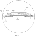
- FIG. 7 is a partially enlarged view of the battery cell 20 shown in FIG. 6 .
- a first concave portion 2331 is formed on one side of the insulating member 233 facing the electrode assembly 22, the first concave portion 2331 is configured to accommodate at least a part of the tab 211 and/or at least a part of the current collecting member 24, a first convex portion 2332 is formed on one side of the insulating member 233 facing away from the electrode assembly 22 at a position corresponding to the first concave portion 2331, a second concave portion 2311 is formed at the side of the end cover 231 facing the electrode assembly 22, and the second concave portion 2311 is used to accommodate the first convex portion 2332.
- the first concave portion 2331 accommodates the at least a part of the tab 221 and/or the at least a part of the current collecting member 24, which can make more space for the electrode assembly 22.
- the first convex portion 2332 is formed on the side of the insulating member 233 facing away from the electrode assembly 22 and corresponding to the first concave portion 2331.
- the first convex portion 2332 can act as a reinforcement at the position where the first concave portion 2331 is provided on the insulating member 233, on the other hand, the arrangement of the first convex portion 2332 can make the first concave portion 2331 be recessed as much as possible along the direction facing away from the electrode assembly 22, so as to increase the recess depth of the first concave portion 2331.
- a second concave portion 2311 is formed on the side of the end cover 231 facing the electrode assembly 22, and the first convex portion 2332 is accommodated in the second concave portion 2311, which reduces the space inside the housing 21 occupied by the insulating member 233 and further makes more space for the electrode assembly 22, thereby effectively increasing the capacity of battery cell 20.
- the first concave portion 2331 is configured to accommodate at least a part of the tab 221 and/or at least a part of the current collecting member 24, that is, the at least a part of the tab 221 is accommodated in the first concave portion 2331, or the at least a part of the current collecting member 24 is accommodated in the first concave portion 2331, or the at least a part of the tab 221 and the at least a part of the current collecting member 24 are both accommodated in the second concave portion 2311.
- shapes of the first concave portion 2331, the first convex portion 2332 and the second concave portion 2311 may be a cylinder, a cuboid, and the like.
- the first concave portion 2332 and the second concave portion 2311 may form a positioning engagement, which can restrict the insulating member 233 from moving relative to the end cover 231 in the direction perpendicular to a thickness direction Z of the end cover 231.
- inserting the first convex portion 2332 into the second concave portion 2311 can realize the positioning of the insulating member 233 and the end cover 231, so as to realize the accurate and rapid assembly of the insulating member 233 and the end cover 231.
- first convex portion 2332 and the first concave portion 2331 form a positioning engagement
- an outer surface of the first convex portion 2332 and an inner surface of the second concave portion 2311 may form a positioning engagement.
- an outer diameter of the first convex portion 2332 matches an inner diameter of the second concave portion 2311
- an outer circumference of the first convex portion 2332 matches an inner circumference of the second concave portion 2311.
- a gap may be presented between the electrode assembly 22 and the insulating member 233 in the thickness direction Z of the end cover 231; the electrode assembly 22 may also abut against the insulating member 233 along the direction facing away from the electrode assembly 22, so that the electrode assembly 22 and the insulating member 233 are more compact, which is beneficial to increase the capacity of the battery cell 20.
- FIG. 7 exemplarily shows a situation that the electrode assembly 22 abuts against the insulating member 233 along the direction facing away from the electrode assembly 22.
- FIG. 8 is a positional relationship diagram of the insulating member 233, the current collecting member 24 and a tab 221 shown in FIG. 7 .
- the tab 221 includes a first connection portion 2211
- the current collecting member 24 includes a second connection portion 241
- the second connection portion 241 is used to connect the first connection portion 2211 of the tab 221.
- the first concave portion 2331 is configured to accommodate at least a part of the first connection portion 2211 and/or at least a part of the second connection portion 241.
- the first connection portion 2211 is the part where the tab 221 is connected to the current collecting member 24, and the second connection portion 241 is the part where the current collecting member 24 is connected to the tab 221.
- the first connection portion 2211 and the second connection portion 241 are welded together.
- first connection portion 2211 and the second connection portion 241 are laminated and distributed in the thickness direction Z of the end cover 22, which is convenient for connecting the first connection portion 2211 and the second connection portion 241 together.
- the first connection portion 2211 and the second connection portion 241 are laminated and distributed in the thickness direction Z of the end cover 231.
- the first connection portion 2211 and the second connection portion 241 as a whole will occupy a relatively large space inside the housing 21, but accommodating at least a part of the first connection portion 2211 of the tab 221 and/or at least a part of the second connection portion 241 of the current collecting member 24 in the first concave portion 2331 can then make more space for the electrode assembly 22.
- FIG. 8 in the thickness direction Z of the end cover 231, the first connection portion 2211 is closer to the electrode assembly 22 than the second connection portion 241 (refer to FIG. 7 ), and the second connection portion 241 is accommodated in the first concave portion 2331.
- FIG. 9 is a positional relationship diagram of the insulating member 233, the current collecting member 24 and the tab 221 provided by still other embodiments of the present application, in the thickness direction Z of the end cover 231, the second connection portion 241 is closer to the electrode assembly 22 than the first connection portion 2211, and the first connection portion 2211 is accommodated in the first concave portion 2331.
- FIG. 10 FIG.
- FIG. 10 is a positional relationship diagram of the insulating member 233, the current collecting member 24 and the tab 221 provided by yet other embodiments of the present application.
- the first connection portion 2211 and the second connection portion 241 are both accommodated in the third concave portion 2331, so as to further make more space for the electrode assembly 22.
- FIG. 11 is a schematic structural diagram of the current collecting member 24 shown in FIG. 7
- the current collecting member 24 may further include a third connection portion 242 and a fourth connection portion 243, where the third connection portion 242 is used to connect to the electrode terminal 232, the third connection portion 242 is connected to the second connection portion 241 through the fourth connection portion 243, the third connection portion 242 and the second connection 241 are spaced apart in the thickness direction Z of the end cover 231.
- the second connection portion 241 may be accommodated in the third concave portion 2331, and the third connection portion 242 may be located on one side of the insulating member 233 close to the electrode assembly 22.
- the second connection portion 241, the fourth connection portion 243 and the third connection portion 242 are sequentially connected to form a "Z"-shaped plate structure.
- one side of the third connection portion 242 closer to the second connection portion 241 is provided with a protrusion 244 used to connect and fix the electrode terminal 232, for example, the protrusion 244 is welded to the electrode terminal 232.
- the second concave portion 2311 may be provided at a plurality of positions of the end cover 231.
- FIG. 12 is a schematic structural diagram of the end cover assembly 23 shown in FIG. 7 , the electrode terminal 232 is staggered from the second concave portion 2311 in a preset direction X (refer to FIG. 7 ), and the preset direction is perpendicular to the thickness direction Z of the end cover 231.
- the electrode terminal 232 is staggered from the second concave portion 2311 in the direction perpendicular to the thickness direction Z of the end cover 231, that is, the electrode terminal 232 is at a distance from the second concave portion 2311 in the preset direction X, so that the second concave portion 2311 is formed outside the area where the end cover 231 is mounted with the electrode terminal 232, and the arrangement of the second concave portion 2311 will not affect the mounting of the electrode terminal 232.
- the preset direction X is a length direction of the end cover 231.
- either one electrode terminal 232 or two electrode terminals can be staggered from the second concave portion 2311 in the preset direction X. It is understandable that if there are two electrode terminals 232 in the end cover assembly 23, the two electrode terminals 232 are both staggered from the second concave portion 2311 in the preset direction X.
- the second concave portion 2311 is located between the two electrode terminals 232 along the preset direction X, that is, the second concave portion 2311 is provided in the area between the two electrode terminals 232 of the end cover 231, so that the two electrode terminals 232 are staggered from the second concave portion 2311 in the preset direction X, and reasonably utilizes the space between the two electrode terminals 232.
- the end cover assembly 23 there are two electrode terminals 232 in the end cover assembly 23, and there may also be two current collecting members 24. Taking the at least a part of the current collecting member 24 accommodated in the first concave portion 2331 as an example, the at least a part of the two current collecting members 24 may both be partially accommodated in the same first concave portion 2331. Of course, two first concave portion 2331 may also be formed on the insulating member 233. The at least a part of one collecting member 24 is accommodated in one first concave portion 2331 and the at least a portion of another collecting member 24 is accommodated in another first concave portion 2331. In the end cover assembly 23 shown in FIG.
- a second concave portion 2311 is formed on the end cover 231
- a first concave portion 2331 and a second convex portion 2314 are formed on the insulating member 233
- the two current collecting members 24 are at least partially accommodated in the first concave portion 2331, for example, the second connection portion 241 of the two current collecting members 24 are both accommodated in the first concave portion 2331.
- the second concave portion 2311 may not be staggered from the electrode terminal 232 in the preset direction X.
- the second concave portion 2311 is formed at the position where the electrode terminal 232 is provided on the end cover 231, and the second concave portion 2311 and the electrode terminal 232 are respectively located on both sides of the end cover 231 in the thickness direction Z.
- FIG. 13 is a partially enlarged view of a point A of the end cover assembly 23 shown in FIG. 12
- the electrode terminal 232 includes a terminal main body 2321 and a connection body 2322, where the terminal main body 2321 is mounted to the end cover 231 through the connection body 2322, and the terminal main body 2321 is used to connect to the current collecting member 24 to realize the electrical connection between the terminal main body 2321 and the tab 221.
- connection body 2322 may be circumferentially coated around the outer circumference of the terminal main body 2321, so as to realize fixation of the connection body 2322 and the terminal main body 2321.
- the connection body 2322 and the end cover 231 may be fixed and connected.
- connection member has a ring structure, and the connection member is welded to the end cover 231.
- the end cover 231 is provided with an electrode extraction hole 2312, and the protrusion 244 (refer to FIG. 11 ) on the third connection portion 242 of the current collecting member 24 can pass through the electrode extraction hole 2312 and be connected and fixed to the electrode terminal 232, for example, the protrusion 244 is welded to the electrode terminal 232.
- the second concave portion 2311 on the end cover 231 has various forms, which will be described in detail below with reference to the accompanying drawings.
- FIG. 14 is a partially enlarged view of a point B of the end cover assembly 23 shown in FIG. 12 , the end cover 231 includes a first body 2313, where the first body 2313 is used to cover the opening.
- the first body 2313 has a first inner surface 2313a facing the electrode assembly 22 (refer to FIG. 7 ), and the second concave portion 2311 is recessed from the first inner surface 2313a along the direction facing away from the electrode assembly 22.
- the end cover 231 of this structure has a simple structure and is easy to be formed and manufactured.
- the end cover 231 further includes a second convex portion 2314; the first body 2313 further has a first outer surface 2313b provided opposite to the first inner surface 2313a, and the second convex portion 2314 is protrudingly provided on the first outer surface 2313b and is located at a position corresponding to the second concave portion 2311.
- the second convex portion 2314 can act as a reinforcement at the position of the first body 2313 where the second concave portion 2311 is provided, and improve the firmness of the end cover 231.
- the second convex portion 2314 has a first end surface 2314a, the second convex portion 2314 extends to the first end surface 2314a from the first outer surface 2313b along the direction facing away from the electrode assembly 22, and the first end surface 2314a does not exceed the electrode terminal 232 in the direction facing away from the electrode assembly 22 (refer to FIG. 12 ).
- the second convex portion 2314 reasonably utilizes the space between the first outer surface 2313b of the first body 2313 and an end portion of the electrode terminal 232, which reduces the risk of increasing the space occupied by the entire battery cell 20 due to the first end surface 2314a exceeding the electrode terminal 232.
- the pressure relief mechanism 234 can be mounted to the end cover 231 in an area corresponding to the second convex portion 2314.
- the second convex portion 2314 may be provided with a pressure relief hole (not shown) that communicates with the second concave portion 2311 and penetrates the first end surface 2314a of the second convex portion 2314, and the rupture plate is mounted to the end cover 231 and blocks the pressure relief hole.
- the second concave portion 2311 has a first bottom wall 2311a, the second concave portion 2311 is recessed to the first bottom wall 2311a from the first inner surface 2313a along the direction facing away from the electrode assembly 22.
- the first bottom wall 2311a exceeds the first outer surface 2313b along the direction facing the electrode assembly 22.
- FIG. 15 is a schematic connection diagram of the insulating member 233 and the end cover 231 provided by yet other embodiments of the present application.
- the first bottom wall 2311a exceeds the first outer surface 2313b along the direction facing away from the electrode assembly 22 (refer to FIG.
- the first outer surface 2313b is closer to the electrode assembly 22 than the first bottom wall 2311a, so that the second concave portion 2311 is recessed to the second convex portion 2314, thereby increasing the recess depth of the second concave portion 2311 and increasing the space of the second concave portion 2311 for accommodating the first convex portion 2332, so that the first convex portion 2332 can extend to a deeper position of the second concave portion 2311.
- the first bottom wall 2311a may also be flush with the first outer surface 2313b.
- the insulating member 233 includes a second body 2333 and a first convex portion 2332.
- the second body 2333 has a second inner surface 2333a and a second outer surface 2333b opposite to each other, the second inner surface 2333a faces the electrode assembly 22, the first concave portion 2331 is recessed from the second inner surface 2333a along the direction facing away from the electrode assembly 22, and the first convex portion 2332 is protrudingly provided on the second outer surface 2333b.
- the second outer surface 2333b abuts against the first inner surface 2313a to eliminate the gap between the second outer surface 2333b and the first inner surface 2313a, so that the first convex portion 2332 may be completely accommodated in the first concave portion 2331 so as to make more space for the electrode assembly 22.
- first convex portion 2332 has a second end surface 2332a, the first convex portion 2332 extends to the second end surface 2333b from the second outer surface 2333b along the direction facing away from the electrode assembly 22.
- a gap is presented between the second end surface 2332a and the first bottom wall 2311a to ensure that the second outer surface 2333b of the second body 2333 may effectively abut against the first inner surface 2313a of the first body 2313, which reduces a risk of over-positioning between the insulating member 233 and the end cover 231.
- the first concave portion 2331 has a second bottom wall 2331a, the first concave portion 2331 is recessed to the second bottom wall 2331a from the second inner surface 2333a along the direction facing away from the electrode assembly 22, the second bottom wall 2331a of the first concave portion 2331 exceeds the second outer surface 2333b in the direction facing away from the electrode assembly 22, so that the first concave portion 2331 is recessed to the first convex portion 2332, thereby increasing the recess depth of the first concave portion 2331 and increasing the space of the first concave portion 2331 for accommodating the tab 221 and/or the current collecting member 24, the tab and/or the current collecting member can be extended to a deeper position of the first concave portion, so as to make more space for the electrode assembly 22.
- the second concave portion 2311 on the end cover 231 can be formed by an inner surface of the first body 2313 being recessed along the direction facing away from the electrode assembly 22.
- the second concave portion 2311 on the end cover 231 can also have other forms.
- FIG. 16 is a partially enlarged view of the battery cell 20 provided by still other embodiments of the present application.
- the end cover 231 includes a first body 2313 and a third convex portion 2315, where the first body 2313 is used to cover the opening of the housing 21.
- the first body 2313 has a first inner surface 2313a facing the electrode assembly 22
- the third convex portion 2315 has a third end surface 2315a
- the third convex portion 2315 extends to the third end surface 2315a from the first inner surface 2313a along the direction facing the electrode assembly 22.
- the second concave portion 2311 is recessed to the first inner surface 2313a from the third end surface 2315a along the direction facing away from the electrode assembly 22. That is, by providing the third convex portion 2315 on the first inner surface 2313a a of the first body 2313, the end cover 231 forms the second concave portion 2311 on the side facing the electrode assembly 22.
- two third convex portions 2315 may be protrudingly provided on the first inner surface 2313a of the first body 2313, where one third convex portion 2315 corresponds to one electrode terminal 232.
- the second concave portion 2311 is formed between the two third convex portions 2315.
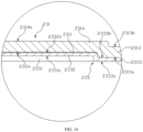
- FIG. 17 is a partially enlarged view of the battery cell 20 shown in FIG. 16 .
- the first body 2313 also has a first outer surface 2313b disposed opposite to the first inner surface 2313a, a third concave portion 2316 recessed from the first outer surface 2313b along the direction facing the electrode assembly 22 is formed on one side of the first body 2313 facing away from the electrode assembly 22 at a position corresponding to the third convex portion 2315, and the third concave portion 2316 is configured to accommodate at least a part of the electrode terminal 232.
- the third concave portion 2316 may be used to accommodate at least a part of the electrode terminal 232, so as to shorten the length of the part of the electrode terminal 232 protruding from the first body 2313.
- the third concave portion 2316 is arranged at the position of the first body 2313 corresponding to the third convex portion 2315, the third convex portion 2315 can make the third concave portion 2316 recess as much as possible along the direction facing the electrode assembly 22, which further shortens the length of the part of the electrode terminal 232 protruding from the first body 2313.
- the electrode terminal 232 is mounted at the bottom of the third concave portion 2316 so that at least a part of the electrode terminal 232 is accommodated in the third concave portion 2316.
- the third concave portion 2316 has a third bottom wall 2316a, the third concave portion 2316 is recessed to the third bottom wall 2316a from the first outer surface 2313b along the direction facing the electrode assembly 22; and the third bottom wall 2316a exceeds the first inner surface 2313a along the direction facing the electrode assembly 22.
- This structure makes the third concave portion 2316 recessed into the third convex portion 2315, thereby increasing the recess depth of the third concave portion 2316, increasing the space of the third concave portion 2316 for accommodating the electrode terminal 232, so that the electrode terminal 232 may be mounted at a deeper position of the third concave portion 2316.
- a fourth concave portion 2317 is provided on the third bottom wall 2316a of the third concave portion 2316, the electrode terminal 232 partially extends to the fourth concave portion 2317, and the part of the electrode terminal 232 extending to the fourth concave portion 2317 abuts against a bottom wall of the fourth concave portion 2317, so as to mount the electrode terminal 232 to the end cover 231.
- connection body 2322 of the electrode terminal 232 partially extends to the fourth concave portion 2317, and the part of the connection body 2322 extending to the fourth concave portion 2317 abuts against the bottom wall of the fourth concave portion 2317, and the connection body 2322 and the end cover 231 may be welded and fixed.
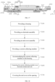
- FIG. 18 is a flowchart of a manufacturing method for the battery cell 20 provided by some embodiments of the present application. The method includes:
- step S100, step S200, step S300, and step S400 is not limited.
- step S400 may be performed first, then followed by step S300, step S200, and step S100.
- step S600 may be performed before step S500, and step S500 may also be performed after step S600.
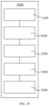
- FIG. 19 is a schematic block diagram of the manufacturing device 2000 for the battery cell 20 provided by some embodiments of the present application.
- the manufacturing device 2000 includes a first providing apparatus 1100, a second providing apparatus 1200, a third providing apparatus 1300 and an assembling apparatus 1500.
- the first providing apparatus 1100 is used for providing a housing 21, the housing 21 having an opening.
- the second providing apparatus 1200 is used for providing an electrode assembly 22, and the electrode assembly 22 includes a tab 221.
- the third providing apparatus 1300 is used for providing an end cover assembly 23, the end cover assembly 23 includes an end cover 231 an electrode terminal 232 and an insulating member 233, and the electrode terminal 232 is mounted to the end cover 231.
- the fourth providing apparatus 1400 is used for providing a current collecting member 24.
- the assembling apparatus 1500 is used for accommodating the electrode assembly 22 in the housing 21, and the assembling apparatus 1500 is used for connecting the current collecting member 24 to the electrode terminal 232 and the tab 221 so that the tab 221 is electrically connected to the electrode terminal 232.
- the assembling apparatus 1500 is further used to cover the end cover 231 at the opening.
- the insulating member 233 is located on the side of the end cover 231 facing the electrode assembly 22, a first concave portion 2331 is formed on the side of the insulating member 233 facing the electrode assembly 22, and the first concave portion 2331 is configured to accommodate the at least a part of the tab 221 and/or the at least a part of the current collecting member 24, a first convex portion 2332 is formed on the side of the insulating member 233 facing away from the electrode assembly 22 at the position corresponding to the first concave portion 2331, a second concave portion 2311 is formed on the side of the end cover 231 facing the electrode assembly 22, and the second concave portion 2311 is used to accommodate the first convex portion 2332.
- the related structure of the battery cell 20 manufactured by the above manufacturing device may refer to the battery cell 20 provided in the above respective embodiments.
Landscapes
- Chemical & Material Sciences (AREA)
- Chemical Kinetics & Catalysis (AREA)
- Electrochemistry (AREA)
- General Chemical & Material Sciences (AREA)
- Connection Of Batteries Or Terminals (AREA)
- Sealing Battery Cases Or Jackets (AREA)
- Secondary Cells (AREA)
Claims (12)
- Batteriezelle (20), die Folgendes umfasst:ein Gehäuse (21) mit einer Öffnung;eine Elektrodenbaugruppe (22), die in dem Gehäuse (21) aufgenommen ist, wobei die Elektrodenbaugruppe (22) eine Lasche (221) umfasst;eine Endabdeckungsbaugruppe (23), die eine Endabdeckung (231), einen Elektrodenanschluss (232) und ein Isolierelement (233) umfasst, wobei die Endabdeckung (231) zur Abdeckung an der Öffnung genutzt wird, der Elektrodenanschluss (232) an der Endabdeckung (231) montiert ist und das Isolierelement (233) sich auf einer der Elektrodenbaugruppe (22) zugewandten Seite der Endabdeckung (231) befindet; undein Stromabnahmeelement (24) zum Verbinden des Elektrodenanschlusses (232) und der Lasche (221), sodass die Lasche (221) elektrisch mit dem Elektrodenanschluss (232) verbunden ist;wobei auf einer der Elektrodenbaugruppe (22) zugewandten Seite des Isolierelements (233) ein erster konkaver Abschnitt (2331) gebildet ist und der erste konkave Abschnitt (2331) so ausgestaltet ist, dass er mindestens einen Teil der Lasche (221) und/oder mindestens einen Teil des Stromabnahmeelements (24) aufnimmt, auf einer von der Elektrodenbaugruppe (22) abgewandten Seite des Isolierelements (233) an einer mit dem ersten konkaven Abschnitt (2331) korrespondierenden Stelle ein erster konvexer Abschnitt (2332) gebildet ist, auf der der Elektrodenbaugruppe (22) zugewandten Seite der Endabdeckung (231) ein zweiter konkaver Abschnitt (2311) gebildet ist und der zweite konkave Abschnitt (2311) zum Aufnehmen des ersten konvexen Abschnitts (2332) genutzt wird;wobei die Endabdeckung (231) einen ersten Körper (2313) umfasst, wobei der erste Körper (2313) zur Abdeckung an der Öffnung genutzt wird; der erste Körper (2313) eine der Elektrodenbaugruppe (22) zugewandte erste innere Oberfläche (2313a) aufweist und der zweite konkave Abschnitt (2311) von der ersten inneren Oberfläche (2313a) entlang einer von der Elektrodenbaugruppe (22) weg weisenden Richtung vertieft ist;wobei die Endabdeckung (231) ferner einen zweiten konvexen Abschnitt (2314) umfasst; der erste Körper (2313) ferner eine gegenüber der ersten inneren Oberfläche (2313a) vorgesehene erste äußere Oberfläche (2313b) aufweist und der zweite konvexe Abschnitt (2314) vorstehend auf der ersten äußeren Oberfläche (2313b) vorgesehen ist und sich an einer mit dem zweiten konkaven Abschnitt (2311) korrespondierenden Stelle befindet; undwobei der zweite konvexe Abschnitt (2314) eine erste Endoberfläche (2314a) aufweist, der zweite konvexe Abschnitt (2314) sich von der ersten äußeren Oberfläche (2313b) entlang der von der Elektrodenbaugruppe (22) weg weisenden Richtung zu der ersten Endoberfläche (2314a) erstreckt und die erste Endoberfläche (2314a) sich in der von der Elektrodenbaugruppe (22) weg weisenden Richtung nicht über den Elektrodenanschluss (232) hinaus erstreckt.
- Batteriezelle (20) nach Anspruch 1, wobei der zweite konkave Abschnitt (2311) eine erste untere Wand (2311a) aufweist, der zweite konkave Abschnitt (2311) von der ersten inneren Oberfläche (2313a) entlang der von der Elektrodenbaugruppe (22) weg weisenden Richtung zu der ersten unteren Wand (2311a) vertieft ist und die erste untere Wand (2311a) sich entlang der von der Elektrodenbaugruppe (22) weg weisenden Richtung über die erste äußere Oberfläche (2313b) hinaus erstreckt.
- Batteriezelle (20) nach Anspruch 1 oder 2, wobei das Isolierelement (233) einen zweiten Körper (2333) und den ersten konvexen Abschnitt (2332) umfasst;
der zweite Körper (2333) eine zweite innere Oberfläche (2333a) und eine zweite äußere Oberfläche (2333b), die sich gegenüberliegen, aufweist, die zweite innere Oberfläche (2333a) der Elektrodenbaugruppe (22) zugewandt ist, der erste konkave Abschnitt (2331) entlang der von der Elektrodenbaugruppe (22) weg weisenden Richtung von der zweiten inneren Oberfläche (2333a) vertieft ist und der erste konvexe Abschnitt (2332) vorstehend auf der zweiten äußeren Oberfläche (2333b) vorgesehen ist. - Batteriezelle (20) nach Anspruch 3, wobei die zweite äußere Oberfläche (2333b) an die erste innere Oberfläche (2313a) grenzt.
- Batteriezelle (20) nach Anspruch 3 oder 4, wobei der erste konvexe Abschnitt (2332) eine zweite Endoberfläche (2332a) aufweist, der erste konvexe Abschnitt (2332) sich von der zweiten äußeren Oberfläche (2333b) entlang der von der Elektrodenbaugruppe (22) weg weisenden Richtung zu der zweiten Endoberfläche (2332a) erstreckt;der zweite konkave Abschnitt (2311) eine erste untere Wand (2311a) aufweist, der zweite konkave Abschnitt (2311) von der ersten inneren Oberfläche (2313a) entlang der von der Elektrodenbaugruppe (22) weg weisenden Richtung zu der ersten unteren Wand (2311a) vertieft ist;wobei zwischen der zweiten Endoberfläche (2332a) und der ersten unteren Wand (2311a) ein Zwischenraum vorhanden ist.
- Batteriezelle (20) nach einem der Ansprüche 3-5, wobei der erste konkave Abschnitt (2331) eine zweite untere Wand (2331a) aufweist, der erste konkave Abschnitt (2331) von der zweiten inneren Oberfläche (2333a) entlang der von der Elektrodenbaugruppe (22) weg weisenden Richtung zu der zweiten unteren Wand vertieft ist und die zweite untere Wand sich entlang der von der Elektrodenbaugruppe (22) weg weisenden Richtung über die zweite äußere Oberfläche (2333b) hinaus erstreckt.
- Batteriezelle (20) nach Anspruch 1, wobei die Endabdeckung (231) einen ersten Körper (2313) und einen dritten konvexen Abschnitt (2315) umfasst, wobei der erste Körper (2313) zur Abdeckung an der Öffnung genutzt wird;der erste Körper (2313) eine der Elektrodenbaugruppe (22) zugewandte erste innere Oberfläche (2313a) aufweist, der dritte konvexe Abschnitt (2315) eine dritte Endoberfläche (2315a) aufweist und der dritte konvexe Abschnitt (2315) sich von der ersten inneren Oberfläche (2313a) entlang einer zu der Elektrodenbaugruppe (22) weisenden Richtung zu der dritten Endoberfläche (2315a) erstreckt; undder zweite konkave Abschnitt (2311) von der dritten Endoberfläche (2315a) entlang der von der Elektrodenbaugruppe (22) weg weisenden Richtung zu der ersten inneren Oberfläche vertieft ist.
- Batteriezelle (20) nach Anspruch 7, wobei der erste Körper (2313) ferner eine der ersten inneren Oberfläche (2313a) gegenüber vorgesehene erste äußere Oberfläche (2313b) aufweist;auf einer von der Elektrodenbaugruppe (22) abgewandten Seite des ersten Körpers (2313) an einer mit dem dritten konvexen Abschnitt (2315) korrespondierenden Stelle ein dritter konkaver Abschnitt (2316), der entlang der zu der Elektrodenbaugruppe (22) weisenden Richtung von der ersten äußeren Oberfläche (2313b) vertieft ist, gebildet ist, wobei der dritte konkave Abschnitt (2316) so ausgestaltet ist, dass er mindestens einen Teil des Elektrodenanschlusses (232) aufnimmt;wobei der dritte konkave Abschnitt (2316) eine dritte untere Wand (2316a) aufweist, der dritte konkave Abschnitt (2316) von der ersten äußeren Oberfläche (2313b) entlang der zu der Elektrodenbaugruppe (22) weisenden Richtung zu der dritten unteren Wand (2316a) vertieft ist; unddie dritte untere Wand (2316a) sich entlang der zu der Elektrodenbaugruppe (22) weisenden Richtung über die erste innere Oberfläche (2313a) hinaus erstreckt.
- Batteriezelle (20) nach einem der Ansprüche 1-8, wobei die Lasche (221) einen ersten Verbindungsabschnitt (2211) umfasst, das Stromabnahmeelement (24) einen zweiten Verbindungsabschnitt (241) zur Verbindung mit dem ersten Verbindungsabschnitt umfasst; und
der erste konkave Abschnitt (2331) so ausgestaltet ist, dass er mindestens einen Teil des ersten Verbindungsabschnitts und/oder mindestens einen Teil des zweiten Verbindungsabschnitts aufnimmt. - Batteriezelle (20) nach Anspruch 9, wobei der erste Verbindungsabschnitt und der zweite Verbindungsabschnitt laminiert und in einer Dickenrichtung der Endabdeckung (231) verteilt und beide in dem ersten konkaven Abschnitt (2331) aufgenommen sind.
- Batteriezelle (20) nach Anspruch 9 oder 10, wobei das Stromabnahmeelement (24) ferner einen dritten Verbindungsabschnitt (242) zur Verbindung mit dem Elektrodenanschluss (232) umfasst und der dritte Verbindungsabschnitt und der zweite Verbindungsabschnitt in der Dickenrichtung der Endabdeckung (231) beabstandet sind.
- Batterie (100), die einen Kastenkörper (10) und die Batteriezelle (20) nach einem der Ansprüche 1-11 umfasst; und
wobei die Batteriezelle (20) in dem Kastenkörper (10) aufgenommen ist.
Priority Applications (1)
| Application Number | Priority Date | Filing Date | Title |
|---|---|---|---|
| HUE21810262A HUE069144T2 (hu) | 2021-02-10 | 2021-02-10 | Akkumulátorcella, akkumulátor és elektromos készülék |
Applications Claiming Priority (1)
| Application Number | Priority Date | Filing Date | Title |
|---|---|---|---|
| PCT/CN2021/076487 WO2022170553A1 (zh) | 2021-02-10 | 2021-02-10 | 电池单体、电池、用电设备及电池单体的制造设备和方法 |
Publications (4)
| Publication Number | Publication Date |
|---|---|
| EP4220788A1 EP4220788A1 (de) | 2023-08-02 |
| EP4220788A4 EP4220788A4 (de) | 2023-09-27 |
| EP4220788B1 true EP4220788B1 (de) | 2024-09-04 |
| EP4220788B8 EP4220788B8 (de) | 2024-10-23 |
Family
ID=82837438
Family Applications (1)
| Application Number | Title | Priority Date | Filing Date |
|---|---|---|---|
| EP21810262.2A Active EP4220788B8 (de) | 2021-02-10 | 2021-02-10 | Batteriezelle, batterie und elektrische vorrichtung |
Country Status (7)
| Country | Link |
|---|---|
| US (1) | US11710872B2 (de) |
| EP (1) | EP4220788B8 (de) |
| JP (1) | JP7684317B2 (de) |
| KR (1) | KR102603536B1 (de) |
| CN (5) | CN121394510A (de) |
| HU (1) | HUE069144T2 (de) |
| WO (1) | WO2022170553A1 (de) |
Families Citing this family (9)
| Publication number | Priority date | Publication date | Assignee | Title |
|---|---|---|---|---|
| WO2022252010A1 (zh) | 2021-05-31 | 2022-12-08 | 宁德时代新能源科技股份有限公司 | 电池单体及其制造方法和制造系统、电池以及用电装置 |
| CN115377623B (zh) * | 2022-09-21 | 2023-10-17 | 厦门海辰储能科技股份有限公司 | 集流件、电池、电池包和用电设备 |
| CN118525410A (zh) * | 2022-10-17 | 2024-08-20 | 宁德时代新能源科技股份有限公司 | 电池单体、电池和用电设备 |
| WO2024164254A1 (zh) * | 2023-02-09 | 2024-08-15 | 深圳海润新能源科技有限公司 | 储能装置及用电设备 |
| CN116014319B (zh) | 2023-02-09 | 2023-06-06 | 深圳海润新能源科技有限公司 | 储能装置及用电设备 |
| CN219419418U (zh) * | 2023-04-07 | 2023-07-25 | 远景动力技术(江苏)有限公司 | 盖板组件及包含其的单体电池 |
| CN220774523U (zh) * | 2024-01-05 | 2024-04-12 | 宁德时代新能源科技股份有限公司 | 电池单体、电池及用电设备 |
| CN222775435U (zh) * | 2024-04-03 | 2025-04-18 | 宁德时代新能源科技股份有限公司 | 电池单体、电池及用电设备 |
| CN222601160U (zh) * | 2024-05-24 | 2025-03-11 | 株式会社Aesc日本 | 电池端盖及电池 |
Family Cites Families (23)
| Publication number | Priority date | Publication date | Assignee | Title |
|---|---|---|---|---|
| EP2752919B1 (de) * | 2011-08-30 | 2017-03-08 | Toyota Jidosha Kabushiki Kaisha | Batterie, montierte batterie und vorrichtung |
| JP5868265B2 (ja) * | 2012-05-25 | 2016-02-24 | 日立オートモティブシステムズ株式会社 | 単電池および組電池 |
| JP5866621B2 (ja) * | 2012-09-27 | 2016-02-17 | トヨタ自動車株式会社 | 蓋体、密閉型電池、および密閉型電池の製造方法 |
| JP5574003B1 (ja) * | 2013-03-29 | 2014-08-20 | 株式会社豊田自動織機 | 蓄電装置 |
| KR101689750B1 (ko) * | 2014-01-21 | 2016-12-26 | 주식회사 엘지화학 | 배터리 팩 |
| KR101808307B1 (ko) | 2014-05-28 | 2017-12-12 | 주식회사 엘지화학 | 단자 커버 및 이를 포함하는 배터리 팩 |
| JP6520097B2 (ja) | 2014-12-11 | 2019-05-29 | 株式会社Gsユアサ | 蓄電素子 |
| US10637035B2 (en) | 2015-03-31 | 2020-04-28 | Gs Yuasa International Ltd. | Energy storage device |
| JP2017059508A (ja) * | 2015-09-18 | 2017-03-23 | リチウム エナジー アンド パワー ゲゼルシャフト ミット ベシュレンクテル ハフッング ウント コンパニー コマンディトゲゼルシャフトLithium Energy and Power GmbH & Co. KG | 蓄電素子 |
| JP2017059509A (ja) * | 2015-09-18 | 2017-03-23 | リチウム エナジー アンド パワー ゲゼルシャフト ミット ベシュレンクテル ハフッング ウント コンパニー コマンディトゲゼルシャフトLithium Energy and Power GmbH & Co. KG | 蓄電素子 |
| CN204946950U (zh) * | 2015-09-21 | 2016-01-06 | 宁德时代新能源科技有限公司 | 动力电池及其顶盖结构 |
| CN110326133A (zh) * | 2017-02-27 | 2019-10-11 | 三洋电机株式会社 | 方形二次电池以及其制造方法 |
| KR102043969B1 (ko) | 2017-04-18 | 2019-11-12 | 주식회사 엘지화학 | 배터리 모듈 |
| JP2019029227A (ja) * | 2017-07-31 | 2019-02-21 | リチウム エナジー アンド パワー ゲゼルシャフト ミット ベシュレンクテル ハフッング ウント コンパニー コマンディトゲゼルシャフトLithium Energy and Power GmbH & Co. KG | 蓄電素子 |
| JP2019053863A (ja) * | 2017-09-13 | 2019-04-04 | 株式会社Gsユアサ | 蓄電素子 |
| CN109920962B (zh) | 2017-12-13 | 2024-09-13 | 比亚迪股份有限公司 | 电池系统及电动汽车 |
| CN207690911U (zh) * | 2018-01-12 | 2018-08-03 | 宁德时代新能源科技股份有限公司 | 二次电池及汽车 |
| CN111656555A (zh) * | 2018-01-31 | 2020-09-11 | 株式会社杰士汤浅国际 | 蓄电元件 |
| CN110797478B (zh) * | 2018-08-01 | 2021-08-24 | 宁德时代新能源科技股份有限公司 | 二次电池 |
| CN111384350B (zh) | 2018-12-29 | 2024-10-15 | 宁德时代新能源科技股份有限公司 | 二次电池以及电池模组 |
| CN111029488B (zh) * | 2019-08-14 | 2021-07-30 | 宁德时代新能源科技股份有限公司 | 二次电池 |
| CN211017134U (zh) * | 2019-12-02 | 2020-07-14 | 宁德时代新能源科技股份有限公司 | 顶盖组件、二次电池、电池模块以及装置 |
| CN211629211U (zh) * | 2020-03-12 | 2020-10-02 | 宁德时代新能源科技股份有限公司 | 二次电池、电池模块以及使用二次电池作为电源的装置 |
-
2021
- 2021-02-10 CN CN202511525142.4A patent/CN121394510A/zh active Pending
- 2021-02-10 HU HUE21810262A patent/HUE069144T2/hu unknown
- 2021-02-10 KR KR1020227025351A patent/KR102603536B1/ko active Active
- 2021-02-10 WO PCT/CN2021/076487 patent/WO2022170553A1/zh not_active Ceased
- 2021-02-10 JP JP2022546099A patent/JP7684317B2/ja active Active
- 2021-02-10 CN CN202511525097.2A patent/CN121282315A/zh active Pending
- 2021-02-10 EP EP21810262.2A patent/EP4220788B8/de active Active
- 2021-02-10 CN CN202180055988.XA patent/CN116114093B/zh active Active
- 2021-02-10 CN CN202511525117.6A patent/CN121282316A/zh active Pending
- 2021-02-10 CN CN202511534442.9A patent/CN121260887A/zh active Pending
-
2022
- 2022-08-22 US US17/892,646 patent/US11710872B2/en active Active
Also Published As
| Publication number | Publication date |
|---|---|
| HUE069144T2 (hu) | 2025-02-28 |
| EP4220788A1 (de) | 2023-08-02 |
| US20220416335A1 (en) | 2022-12-29 |
| KR102603536B1 (ko) | 2023-11-16 |
| CN121260887A (zh) | 2026-01-02 |
| US11710872B2 (en) | 2023-07-25 |
| WO2022170553A1 (zh) | 2022-08-18 |
| CN121282315A (zh) | 2026-01-06 |
| EP4220788A4 (de) | 2023-09-27 |
| KR20220119683A (ko) | 2022-08-30 |
| CN121394510A (zh) | 2026-01-23 |
| JP7684317B2 (ja) | 2025-05-27 |
| CN116114093A (zh) | 2023-05-12 |
| JP2023517820A (ja) | 2023-04-27 |
| CN116114093B (zh) | 2025-11-18 |
| EP4220788B8 (de) | 2024-10-23 |
| CN116114093A8 (zh) | 2024-05-14 |
| CN121282316A (zh) | 2026-01-06 |
Similar Documents
| Publication | Publication Date | Title |
|---|---|---|
| EP4220788B1 (de) | Batteriezelle, batterie und elektrische vorrichtung | |
| EP4167368B1 (de) | Batteriezelle, batterie, stromverbrauchsgerät, verfahren und vorrichtung zur herstellung einer batteriezelle | |
| EP4148889B1 (de) | Batteriezelle, herstellungsverfahren und herstellungssystem dafür, batterie und elektrische vorrichtung | |
| JP7518300B2 (ja) | 電池セル、電池、電力消費機器及び電池セルの製造方法と機器 | |
| EP4485660A1 (de) | Gehäuse, batteriezelle, batterie und elektrische vorrichtung | |
| EP4293769A1 (de) | Batteriezelle, batterie und elektrische vorrichtung | |
| US20240283099A1 (en) | Battery cell, battery, power consumption device, and method and device for producing battery cell | |
| US20230369711A1 (en) | End cap, battery cell, battery and power consuming device | |
| KR102947705B1 (ko) | 배터리 셀, 배터리, 전기기기 및 배터리 셀의 제조 방법 및 장비 | |
| US20240055705A1 (en) | Battery cell, battery, power consuming apparatus, and method and apparatus for manufacturing battery cell | |
| EP4425691A1 (de) | Batteriezelle, batterie und elektrische vorrichtung | |
| EP4060783B1 (de) | Elektrodenanordnung, batteriezelle und batterie | |
| US20240347824A1 (en) | End cover assembly, battery cell, battery, and electrical device | |
| EP4507083A1 (de) | Batteriezelle und herstellungsverfahren dafür sowie batterie und elektrische vorrichtung | |
| EP4068477B1 (de) | Batteriezelle und batterie | |
| US20250070377A1 (en) | Pressure relief device, battery cell, battery, electrical apparatus, and manufacturing method | |
| US20250096400A1 (en) | Battery cell, battery, electrical device and method for wrapping around battery cell with insulating film | |
| US20240396127A1 (en) | End cover assembly, battery cell, battery, and electrical device | |
| EP4376194A1 (de) | Schale, zelle, batterie und elektrische vorrichtung | |
| EP4152491A1 (de) | Batteriezelle, batterie, stromverbrauchende vorrichtung sowie verfahren und vorrichtung zur herstellung einer batteriezelle |
Legal Events
| Date | Code | Title | Description |
|---|---|---|---|
| STAA | Information on the status of an ep patent application or granted ep patent |
Free format text: STATUS: UNKNOWN |
|
| STAA | Information on the status of an ep patent application or granted ep patent |
Free format text: STATUS: THE INTERNATIONAL PUBLICATION HAS BEEN MADE |
|
| PUAI | Public reference made under article 153(3) epc to a published international application that has entered the european phase |
Free format text: ORIGINAL CODE: 0009012 |
|
| STAA | Information on the status of an ep patent application or granted ep patent |
Free format text: STATUS: REQUEST FOR EXAMINATION WAS MADE |
|
| 17P | Request for examination filed |
Effective date: 20211130 |
|
| AK | Designated contracting states |
Kind code of ref document: A1 Designated state(s): AL AT BE BG CH CY CZ DE DK EE ES FI FR GB GR HR HU IE IS IT LI LT LU LV MC MK MT NL NO PL PT RO RS SE SI SK SM TR |
|
| REG | Reference to a national code |
Ref country code: DE Free format text: PREVIOUS MAIN CLASS: H01M0010000000 Ref country code: DE Ref legal event code: R079 Ref document number: 602021018444 Country of ref document: DE Free format text: PREVIOUS MAIN CLASS: H01M0010000000 Ipc: H01M0010052000 |
|
| A4 | Supplementary search report drawn up and despatched |
Effective date: 20230824 |
|
| RIC1 | Information provided on ipc code assigned before grant |
Ipc: H01M 50/209 20210101ALI20230818BHEP Ipc: H01M 50/15 20210101ALI20230818BHEP Ipc: H01M 50/103 20210101ALI20230818BHEP Ipc: H01M 10/052 20100101AFI20230818BHEP |
|
| DAV | Request for validation of the european patent (deleted) | ||
| DAX | Request for extension of the european patent (deleted) | ||
| GRAP | Despatch of communication of intention to grant a patent |
Free format text: ORIGINAL CODE: EPIDOSNIGR1 |
|
| STAA | Information on the status of an ep patent application or granted ep patent |
Free format text: STATUS: GRANT OF PATENT IS INTENDED |
|
| RIC1 | Information provided on ipc code assigned before grant |
Ipc: H01M 50/209 20210101ALI20240521BHEP Ipc: H01M 50/15 20210101ALI20240521BHEP Ipc: H01M 50/103 20210101ALI20240521BHEP Ipc: H01M 10/052 20100101AFI20240521BHEP |
|
| INTG | Intention to grant announced |
Effective date: 20240613 |
|
| RIN1 | Information on inventor provided before grant (corrected) |
Inventor name: YANG, JIANDONG Inventor name: ZHOU, LINGGANG Inventor name: GUO, ZHIJUN Inventor name: JIN, HAIZU Inventor name: XU, JINMEI Inventor name: HUANG, SIYING Inventor name: YANG, JIANXIONG |
|
| GRAS | Grant fee paid |
Free format text: ORIGINAL CODE: EPIDOSNIGR3 |
|
| GRAA | (expected) grant |
Free format text: ORIGINAL CODE: 0009210 |
|
| STAA | Information on the status of an ep patent application or granted ep patent |
Free format text: STATUS: THE PATENT HAS BEEN GRANTED |
|
| AK | Designated contracting states |
Kind code of ref document: B1 Designated state(s): AL AT BE BG CH CY CZ DE DK EE ES FI FR GB GR HR HU IE IS IT LI LT LU LV MC MK MT NL NO PL PT RO RS SE SI SK SM TR |
|
| REG | Reference to a national code |
Ref country code: GB Ref legal event code: FG4D |
|
| REG | Reference to a national code |
Ref country code: CH Ref legal event code: EP |
|
| REG | Reference to a national code |
Ref country code: DE Ref legal event code: R081 Ref document number: 602021018444 Country of ref document: DE Owner name: CONTEMPORARY AMPEREX TECHNOLOGY (HONG KONG) LI, HK Free format text: FORMER OWNER: CONTEMPORARY AMPEREX TECHNOLOGY CO., LIMITED, NINGDE, FUJIAN, CN |
|
| REG | Reference to a national code |
Ref country code: IE Ref legal event code: FG4D |
|
| REG | Reference to a national code |
Ref country code: DE Ref legal event code: R096 Ref document number: 602021018444 Country of ref document: DE |
|
| REG | Reference to a national code |
Ref country code: CH Ref legal event code: PK Free format text: BERICHTIGUNG B8 |
|
| RAP2 | Party data changed (patent owner data changed or rights of a patent transferred) |
Owner name: CONTEMPORARY AMPEREX TECHNOLOGY(HONG KONG) LIMITED |
|
| P01 | Opt-out of the competence of the unified patent court (upc) registered |
Free format text: CASE NUMBER: APP_52998/2024 Effective date: 20240923 |
|
| REG | Reference to a national code |
Ref country code: NL Ref legal event code: FP |
|
| REG | Reference to a national code |
Ref country code: LT Ref legal event code: MG9D |
|
| PG25 | Lapsed in a contracting state [announced via postgrant information from national office to epo] |
Ref country code: PL Free format text: LAPSE BECAUSE OF FAILURE TO SUBMIT A TRANSLATION OF THE DESCRIPTION OR TO PAY THE FEE WITHIN THE PRESCRIBED TIME-LIMIT Effective date: 20240904 Ref country code: GR Free format text: LAPSE BECAUSE OF FAILURE TO SUBMIT A TRANSLATION OF THE DESCRIPTION OR TO PAY THE FEE WITHIN THE PRESCRIBED TIME-LIMIT Effective date: 20241205 Ref country code: FI Free format text: LAPSE BECAUSE OF FAILURE TO SUBMIT A TRANSLATION OF THE DESCRIPTION OR TO PAY THE FEE WITHIN THE PRESCRIBED TIME-LIMIT Effective date: 20240904 |
|
| PG25 | Lapsed in a contracting state [announced via postgrant information from national office to epo] |
Ref country code: BG Free format text: LAPSE BECAUSE OF FAILURE TO SUBMIT A TRANSLATION OF THE DESCRIPTION OR TO PAY THE FEE WITHIN THE PRESCRIBED TIME-LIMIT Effective date: 20240904 |
|
| PG25 | Lapsed in a contracting state [announced via postgrant information from national office to epo] |
Ref country code: LV Free format text: LAPSE BECAUSE OF FAILURE TO SUBMIT A TRANSLATION OF THE DESCRIPTION OR TO PAY THE FEE WITHIN THE PRESCRIBED TIME-LIMIT Effective date: 20240904 |
|
| PG25 | Lapsed in a contracting state [announced via postgrant information from national office to epo] |
Ref country code: HR Free format text: LAPSE BECAUSE OF FAILURE TO SUBMIT A TRANSLATION OF THE DESCRIPTION OR TO PAY THE FEE WITHIN THE PRESCRIBED TIME-LIMIT Effective date: 20240904 |
|
| PG25 | Lapsed in a contracting state [announced via postgrant information from national office to epo] |
Ref country code: ES Free format text: LAPSE BECAUSE OF FAILURE TO SUBMIT A TRANSLATION OF THE DESCRIPTION OR TO PAY THE FEE WITHIN THE PRESCRIBED TIME-LIMIT Effective date: 20240904 Ref country code: RS Free format text: LAPSE BECAUSE OF FAILURE TO SUBMIT A TRANSLATION OF THE DESCRIPTION OR TO PAY THE FEE WITHIN THE PRESCRIBED TIME-LIMIT Effective date: 20241204 |
|
| PG25 | Lapsed in a contracting state [announced via postgrant information from national office to epo] |
Ref country code: RS Free format text: LAPSE BECAUSE OF FAILURE TO SUBMIT A TRANSLATION OF THE DESCRIPTION OR TO PAY THE FEE WITHIN THE PRESCRIBED TIME-LIMIT Effective date: 20241204 Ref country code: PL Free format text: LAPSE BECAUSE OF FAILURE TO SUBMIT A TRANSLATION OF THE DESCRIPTION OR TO PAY THE FEE WITHIN THE PRESCRIBED TIME-LIMIT Effective date: 20240904 Ref country code: LV Free format text: LAPSE BECAUSE OF FAILURE TO SUBMIT A TRANSLATION OF THE DESCRIPTION OR TO PAY THE FEE WITHIN THE PRESCRIBED TIME-LIMIT Effective date: 20240904 Ref country code: HR Free format text: LAPSE BECAUSE OF FAILURE TO SUBMIT A TRANSLATION OF THE DESCRIPTION OR TO PAY THE FEE WITHIN THE PRESCRIBED TIME-LIMIT Effective date: 20240904 Ref country code: GR Free format text: LAPSE BECAUSE OF FAILURE TO SUBMIT A TRANSLATION OF THE DESCRIPTION OR TO PAY THE FEE WITHIN THE PRESCRIBED TIME-LIMIT Effective date: 20241205 Ref country code: FI Free format text: LAPSE BECAUSE OF FAILURE TO SUBMIT A TRANSLATION OF THE DESCRIPTION OR TO PAY THE FEE WITHIN THE PRESCRIBED TIME-LIMIT Effective date: 20240904 Ref country code: ES Free format text: LAPSE BECAUSE OF FAILURE TO SUBMIT A TRANSLATION OF THE DESCRIPTION OR TO PAY THE FEE WITHIN THE PRESCRIBED TIME-LIMIT Effective date: 20240904 Ref country code: BG Free format text: LAPSE BECAUSE OF FAILURE TO SUBMIT A TRANSLATION OF THE DESCRIPTION OR TO PAY THE FEE WITHIN THE PRESCRIBED TIME-LIMIT Effective date: 20240904 |
|
| REG | Reference to a national code |
Ref country code: AT Ref legal event code: MK05 Ref document number: 1721373 Country of ref document: AT Kind code of ref document: T Effective date: 20240904 |
|
| REG | Reference to a national code |
Ref country code: HU Ref legal event code: AG4A Ref document number: E069144 Country of ref document: HU |
|
| PG25 | Lapsed in a contracting state [announced via postgrant information from national office to epo] |
Ref country code: PT Free format text: LAPSE BECAUSE OF FAILURE TO SUBMIT A TRANSLATION OF THE DESCRIPTION OR TO PAY THE FEE WITHIN THE PRESCRIBED TIME-LIMIT Effective date: 20250106 Ref country code: IS Free format text: LAPSE BECAUSE OF FAILURE TO SUBMIT A TRANSLATION OF THE DESCRIPTION OR TO PAY THE FEE WITHIN THE PRESCRIBED TIME-LIMIT Effective date: 20250104 |
|
| PG25 | Lapsed in a contracting state [announced via postgrant information from national office to epo] |
Ref country code: RO Free format text: LAPSE BECAUSE OF FAILURE TO SUBMIT A TRANSLATION OF THE DESCRIPTION OR TO PAY THE FEE WITHIN THE PRESCRIBED TIME-LIMIT Effective date: 20240904 Ref country code: SM Free format text: LAPSE BECAUSE OF FAILURE TO SUBMIT A TRANSLATION OF THE DESCRIPTION OR TO PAY THE FEE WITHIN THE PRESCRIBED TIME-LIMIT Effective date: 20240904 |
|
| PG25 | Lapsed in a contracting state [announced via postgrant information from national office to epo] |
Ref country code: AT Free format text: LAPSE BECAUSE OF FAILURE TO SUBMIT A TRANSLATION OF THE DESCRIPTION OR TO PAY THE FEE WITHIN THE PRESCRIBED TIME-LIMIT Effective date: 20240904 |
|
| PG25 | Lapsed in a contracting state [announced via postgrant information from national office to epo] |
Ref country code: CZ Free format text: LAPSE BECAUSE OF FAILURE TO SUBMIT A TRANSLATION OF THE DESCRIPTION OR TO PAY THE FEE WITHIN THE PRESCRIBED TIME-LIMIT Effective date: 20240904 |
|
| PG25 | Lapsed in a contracting state [announced via postgrant information from national office to epo] |
Ref country code: SK Free format text: LAPSE BECAUSE OF FAILURE TO SUBMIT A TRANSLATION OF THE DESCRIPTION OR TO PAY THE FEE WITHIN THE PRESCRIBED TIME-LIMIT Effective date: 20240904 |
|
| REG | Reference to a national code |
Ref country code: DE Ref legal event code: R097 Ref document number: 602021018444 Country of ref document: DE |
|
| PG25 | Lapsed in a contracting state [announced via postgrant information from national office to epo] |
Ref country code: DK Free format text: LAPSE BECAUSE OF FAILURE TO SUBMIT A TRANSLATION OF THE DESCRIPTION OR TO PAY THE FEE WITHIN THE PRESCRIBED TIME-LIMIT Effective date: 20240904 |
|
| PLBE | No opposition filed within time limit |
Free format text: ORIGINAL CODE: 0009261 |
|
| STAA | Information on the status of an ep patent application or granted ep patent |
Free format text: STATUS: NO OPPOSITION FILED WITHIN TIME LIMIT |
|
| 26N | No opposition filed |
Effective date: 20250605 |
|
| PG25 | Lapsed in a contracting state [announced via postgrant information from national office to epo] |
Ref country code: SE Free format text: LAPSE BECAUSE OF FAILURE TO SUBMIT A TRANSLATION OF THE DESCRIPTION OR TO PAY THE FEE WITHIN THE PRESCRIBED TIME-LIMIT Effective date: 20240904 |
|
| PG25 | Lapsed in a contracting state [announced via postgrant information from national office to epo] |
Ref country code: MC Free format text: LAPSE BECAUSE OF FAILURE TO SUBMIT A TRANSLATION OF THE DESCRIPTION OR TO PAY THE FEE WITHIN THE PRESCRIBED TIME-LIMIT Effective date: 20240904 |
|
| REG | Reference to a national code |
Ref country code: CH Ref legal event code: PL |
|
| PG25 | Lapsed in a contracting state [announced via postgrant information from national office to epo] |
Ref country code: LU Free format text: LAPSE BECAUSE OF NON-PAYMENT OF DUE FEES Effective date: 20250210 |
|
| PG25 | Lapsed in a contracting state [announced via postgrant information from national office to epo] |
Ref country code: CH Free format text: LAPSE BECAUSE OF NON-PAYMENT OF DUE FEES Effective date: 20250228 |
|
| REG | Reference to a national code |
Ref country code: BE Ref legal event code: MM Effective date: 20250228 |
|
| PG25 | Lapsed in a contracting state [announced via postgrant information from national office to epo] |
Ref country code: BE Free format text: LAPSE BECAUSE OF NON-PAYMENT OF DUE FEES Effective date: 20250228 |
|
| PG25 | Lapsed in a contracting state [announced via postgrant information from national office to epo] |
Ref country code: IE Free format text: LAPSE BECAUSE OF NON-PAYMENT OF DUE FEES Effective date: 20250210 |
|
| PGFP | Annual fee paid to national office [announced via postgrant information from national office to epo] |
Ref country code: NL Payment date: 20260220 Year of fee payment: 6 |
|
| PGFP | Annual fee paid to national office [announced via postgrant information from national office to epo] |
Ref country code: HU Payment date: 20260211 Year of fee payment: 6 |
|
| PGFP | Annual fee paid to national office [announced via postgrant information from national office to epo] |
Ref country code: GB Payment date: 20260224 Year of fee payment: 6 |
|
| PGFP | Annual fee paid to national office [announced via postgrant information from national office to epo] |
Ref country code: NO Payment date: 20260224 Year of fee payment: 6 Ref country code: DE Payment date: 20260223 Year of fee payment: 6 |
|
| PGFP | Annual fee paid to national office [announced via postgrant information from national office to epo] |
Ref country code: IT Payment date: 20260223 Year of fee payment: 6 |
|
| PGFP | Annual fee paid to national office [announced via postgrant information from national office to epo] |
Ref country code: FR Payment date: 20260224 Year of fee payment: 6 |