EP4220879A1 - Procédé d'alignement temporel de dispositif de protection différentielle, dispositif de protection différentielle et système de protection différentielle - Google Patents
Procédé d'alignement temporel de dispositif de protection différentielle, dispositif de protection différentielle et système de protection différentielle Download PDFInfo
- Publication number
- EP4220879A1 EP4220879A1 EP23305113.5A EP23305113A EP4220879A1 EP 4220879 A1 EP4220879 A1 EP 4220879A1 EP 23305113 A EP23305113 A EP 23305113A EP 4220879 A1 EP4220879 A1 EP 4220879A1
- Authority
- EP
- European Patent Office
- Prior art keywords
- current
- values
- value
- fourier
- resampled
- Prior art date
- Legal status (The legal status is an assumption and is not a legal conclusion. Google has not performed a legal analysis and makes no representation as to the accuracy of the status listed.)
- Granted
Links
Images




Classifications
-
- G—PHYSICS
- G01—MEASURING; TESTING
- G01R—MEASURING ELECTRIC VARIABLES; MEASURING MAGNETIC VARIABLES
- G01R19/00—Arrangements for measuring currents or voltages or for indicating presence or sign thereof
- G01R19/25—Arrangements for measuring currents or voltages or for indicating presence or sign thereof using digital measurement techniques
- G01R19/2506—Arrangements for conditioning or analysing measured signals, e.g. for indicating peak values ; Details concerning sampling, digitizing or waveform capturing
- G01R19/2509—Details concerning sampling, digitizing or waveform capturing
-
- H—ELECTRICITY
- H02—GENERATION; CONVERSION OR DISTRIBUTION OF ELECTRIC POWER
- H02H—EMERGENCY PROTECTIVE CIRCUIT ARRANGEMENTS
- H02H1/00—Details of emergency protective circuit arrangements
- H02H1/0092—Details of emergency protective circuit arrangements concerning the data processing means, e.g. expert systems, neural networks
-
- H—ELECTRICITY
- H04—ELECTRIC COMMUNICATION TECHNIQUE
- H04J—MULTIPLEX COMMUNICATION
- H04J3/00—Time-division multiplex systems
- H04J3/02—Details
- H04J3/06—Synchronising arrangements
- H04J3/0635—Clock or time synchronisation in a network
-
- H—ELECTRICITY
- H02—GENERATION; CONVERSION OR DISTRIBUTION OF ELECTRIC POWER
- H02H—EMERGENCY PROTECTIVE CIRCUIT ARRANGEMENTS
- H02H3/00—Emergency protective circuit arrangements for automatic disconnection directly responsive to an undesired change from normal electric working condition with or without subsequent reconnection ; integrated protection
- H02H3/26—Emergency protective circuit arrangements for automatic disconnection directly responsive to an undesired change from normal electric working condition with or without subsequent reconnection ; integrated protection responsive to difference between voltages or between currents; responsive to phase angle between voltages or between currents
- H02H3/28—Emergency protective circuit arrangements for automatic disconnection directly responsive to an undesired change from normal electric working condition with or without subsequent reconnection ; integrated protection responsive to difference between voltages or between currents; responsive to phase angle between voltages or between currents involving comparison of the voltage or current values at two spaced portions of a single system, e.g. at opposite ends of one line, at input and output of apparatus
- H02H3/30—Emergency protective circuit arrangements for automatic disconnection directly responsive to an undesired change from normal electric working condition with or without subsequent reconnection ; integrated protection responsive to difference between voltages or between currents; responsive to phase angle between voltages or between currents involving comparison of the voltage or current values at two spaced portions of a single system, e.g. at opposite ends of one line, at input and output of apparatus using pilot wires or other signalling channel
- H02H3/305—Emergency protective circuit arrangements for automatic disconnection directly responsive to an undesired change from normal electric working condition with or without subsequent reconnection ; integrated protection responsive to difference between voltages or between currents; responsive to phase angle between voltages or between currents involving comparison of the voltage or current values at two spaced portions of a single system, e.g. at opposite ends of one line, at input and output of apparatus using pilot wires or other signalling channel involving current comparison
-
- H—ELECTRICITY
- H02—GENERATION; CONVERSION OR DISTRIBUTION OF ELECTRIC POWER
- H02H—EMERGENCY PROTECTIVE CIRCUIT ARRANGEMENTS
- H02H7/00—Emergency protective circuit arrangements specially adapted for specific types of electric machines or apparatus or for sectionalised protection of cable or line systems, and effecting automatic switching in the event of an undesired change from normal working conditions
- H02H7/22—Emergency protective circuit arrangements specially adapted for specific types of electric machines or apparatus or for sectionalised protection of cable or line systems, and effecting automatic switching in the event of an undesired change from normal working conditions for distribution gear, e.g. bus-bar systems; for switching devices
- H02H7/226—Emergency protective circuit arrangements specially adapted for specific types of electric machines or apparatus or for sectionalised protection of cable or line systems, and effecting automatic switching in the event of an undesired change from normal working conditions for distribution gear, e.g. bus-bar systems; for switching devices for wires or cables, e.g. heating wires
-
- H—ELECTRICITY
- H02—GENERATION; CONVERSION OR DISTRIBUTION OF ELECTRIC POWER
- H02H—EMERGENCY PROTECTIVE CIRCUIT ARRANGEMENTS
- H02H7/00—Emergency protective circuit arrangements specially adapted for specific types of electric machines or apparatus or for sectionalised protection of cable or line systems, and effecting automatic switching in the event of an undesired change from normal working conditions
- H02H7/26—Sectionalised protection of cable or line systems, e.g. for disconnecting a section on which a short-circuit, earth fault, or arc discharge has occured
- H02H7/261—Sectionalised protection of cable or line systems, e.g. for disconnecting a section on which a short-circuit, earth fault, or arc discharge has occured involving signal transmission between at least two stations
- H02H7/263—Sectionalised protection of cable or line systems, e.g. for disconnecting a section on which a short-circuit, earth fault, or arc discharge has occured involving signal transmission between at least two stations involving transmissions of measured values
-
- H—ELECTRICITY
- H04—ELECTRIC COMMUNICATION TECHNIQUE
- H04L—TRANSMISSION OF DIGITAL INFORMATION, e.g. TELEGRAPHIC COMMUNICATION
- H04L12/00—Data switching networks
- H04L12/28—Data switching networks characterised by path configuration, e.g. LAN [Local Area Networks] or WAN [Wide Area Networks]
- H04L12/40—Bus networks
-
- H—ELECTRICITY
- H04—ELECTRIC COMMUNICATION TECHNIQUE
- H04Q—SELECTING
- H04Q9/00—Arrangements in telecontrol or telemetry systems for selectively calling a substation from a main station, in which substation desired apparatus is selected for applying a control signal thereto or for obtaining measured values therefrom
-
- G—PHYSICS
- G01—MEASURING; TESTING
- G01R—MEASURING ELECTRIC VARIABLES; MEASURING MAGNETIC VARIABLES
- G01R19/00—Arrangements for measuring currents or voltages or for indicating presence or sign thereof
- G01R19/25—Arrangements for measuring currents or voltages or for indicating presence or sign thereof using digital measurement techniques
- G01R19/2513—Arrangements for monitoring electric power systems, e.g. power lines or loads; Logging
-
- H—ELECTRICITY
- H04—ELECTRIC COMMUNICATION TECHNIQUE
- H04Q—SELECTING
- H04Q2209/00—Arrangements in telecontrol or telemetry systems
- H04Q2209/30—Arrangements in telecontrol or telemetry systems using a wired architecture
Definitions
- This disclosure relates to a time alignment method of a differential protection device for a power line, a differential protection device that performs the time alignment method, and a differential protection system comprising the differential protection device.
- the differential protection device needs to obtain current sampled values from each end (two or more ends) of the differential protection areas, and these current sampled values must be aligned in time.
- parallel cables are used to communicate between the process level and bay level of the substation automation system.
- the differential protection device receives the current analog values directly from the current transformer and then converts and time-aligns the current analog values using the pulse per second (PPS) signal generated by its own satellite positioning module as the reference time.
- PPS pulse per second
- the differential protection device receives the current sampled value packets from the merging unit via the process bus. In this case, if the differential protection device still uses the PPS signal generated by its own satellite positioning module as the reference time, there may be a large error in time alignment results in case of, for example, through faults, which may cause a large safety risk.
- an aspect of this disclosure provides a time alignment method for a differential protection device for the power line.
- the method comprises: obtaining, from a merging unit of the power line, a plurality of current sampled values of the power line and a count value of each of the plurality of current sampled values, a sampling moment of a current sampled value whose count value is a first value in the plurality of current sampled values is a moment of generation of a PPS signal of a satellite positioning module of the merging unit; resampling the plurality of current sampled values according to a sampling frequency of J points/cycle of the differential protection device to obtain a plurality of current resampled values, the plurality of current resampled values comprises a reference current resampled value corresponding to the current sampled value whose count value is the first value, wherein J is an integer greater than 1; and performing Fourier transform on the plurality of current resampled values to obtain a plurality of temporally
- the device comprises a communication module, a sampling module, and a time alignment module.
- the communication module is configured for obtaining, from a merging unit of the power line, a plurality of current sampled values of the power line and a count value of each of the plurality of current sampled values, a sampling moment of a current sampled value whose count value is a first value in the plurality of current sampled values is a moment of generation of a PPS signal of a satellite positioning module of the merging unit.
- the sampling module is configured for resampling the plurality of current sampled values according to a sampling frequency of J points/cycle of the differential protection device to obtain a plurality of current resampled values, the plurality of current resampled values comprises a reference current resampled value corresponding to the current sampled value whose count value is the first value, wherein J is an integer greater than 1.
- the time alignment module is configured for performing Fourier transform on the plurality of current resampled values to obtain a plurality of temporally arranged current Fourier values, the plurality of current Fourier values comprises a reference current Fourier value corresponding to the sampling moment of the current sampled value whose count value is the first value in the plurality of current sampled values, and the reference current Fourier value is determined based on the reference current resampled value and the J-1 current resampled values that temporally arranged before the reference current resampled value.
- the system comprises a current transformer, a merging unit and a differential protection device.
- the current transformer is configured for measuring current analog values of the power line.
- the merging unit is configured for generating a plurality of original current sampled values by sampling the current analog values, obtaining a plurality of current sampled values by interpolating the plurality of original current sampled values, and tagging each current sampled value with a count value, a sampling moment of a current sampled value whose count value is a first value in the plurality of current sampled values is a moment of generation of a PPS signal of a satellite positioning module of the merging unit.
- the differential protection device is for obtaining, from a merging unit of the power line, a plurality of current sampled values of the power line and a count value of each current sampled value; resampling the plurality of current sampled values according to a sampling frequency of J points/cycle of the differential protection device to obtain a plurality of current resampled values, the plurality of current resampled values comprises a reference current resampled value corresponding to the current sampled value whose count value is the first value, wherein J is an integer greater than 1; and performing Fourier transform on the plurality of current resampled values to obtain a plurality of temporally arranged current Fourier values, the plurality of current Fourier values comprises a reference current Fourier value corresponding to the sampling moment of the current sampled value whose count value is the first value in the plurality of current sampled values, and the reference current Fourier value is determined based on the reference current resampled value and the J-1 current resampled values that temporally
- FIG. 1 is a schematic diagram of the differential protection principle of the power line.
- the principle of differential protection of power line L is to determine whether the differential protection action for power line L should be triggered (e.g., to disconnect the associated circuit breaker, etc.) according to whether the differential current of the power line L is zero, i.e., whether the vector sum of currents I 1 and I 2 at both ends of the power line L is zero.
- the differential protection action of the power line L can be triggered according to the following criteria.
- I s 1 , I s 2 , k 1 and k 2 may be selected according to the actual situation of the power line L.
- I 1 and I 2 herein refer to the fundamental wave components of the currents I1 and I2 at the two ends of the power line L, respectively.
- FIG. 1 shows the power line L including two ends as the protection area for example only, and the protection area including more ends is also possible.
- one side of the protection area is a busbar substation and the other sides of the protection area contain individual substations for multiple branches, for the differential protection device of the busbar substation, it is needed to consider the total vector sum of the current information on the one side and the current information of the individual substations on the other sides to determine whether the differential protection action for the protection area should be triggered.
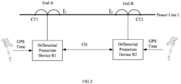
- FIG. 2 is a diagram of an example usage scenario of a time alignment method according to the prior art.
- the time alignment method according to the prior art is applicable to a substation automation system whose process level and bay level are connected by parallel cables therebetween, and the substations at the end A and end B of the power line L illustrated in FIG. 2 is such substation automation system.
- the current transformer CT1 as a process level device of the substation automation system at end A, measures the current analog values of end A.
- the differential protection device R1 as a bay level device of the substation automation system at end A, receives the current analog values from the current transformer CT1 via the parallel cables, and then processes the current analog values of end A according to the time alignment method according to the prior art to convert them into a time-aligned current digital values of end A.
- the arrangement at end B is similar to that at end A.
- the differential protection device R1 also processes the current analog values of end B according to the time alignment method according to the prior art to convert them into the time-aligned current digital values of end B.
- the differential protection devices R1 and R2 exchange the time-aligned current digital values between each other via the communication channel CH, and then make a differential protection decision on whether to trigger differential protection action based on the principle of differential protection shown in FIG. 1 .
- Each of the differential protection devices R1 and R2 has the satellite positioning module, which can receive a reference time source from a time-giving system such as Global Positioning System (GPS), BeiDou System (BDS), Galileo system and GLONASS and the like, and correct their own time based on the reference time source and generate PPS signal per second.
- a time-giving system such as Global Positioning System (GPS), BeiDou System (BDS), Galileo system and GLONASS and the like.
- FIG. 3 is a diagram illustrating an example of a time alignment method according to the prior art.
- the time alignment method according to the prior art may be performed by the differential protection device R1 and/or R2 in FIG. 1 .
- the method can be summarized, for example, in the following three steps: in the first step, the differential protection device R1 receives the current analog values from the current transformer CT1; in the second step, the differential protection device R1 samples the current analog values to obtain the current sampled values; in the third step, the differential protection device R uses the PPS signal generated by its own satellite positioning module as the reference time and performs Fourier transform on the obtained current sampled values to obtain a plurality of current Fourier values.
- the differential protection device R1 receives the current analog values from the current transformer CT1, as the sine wave in illustration 310 in FIG. 3 .
- the differential protection device R1 samples the current analog values according to its sampling frequency. Given the power frequency of 50 Hz and the sampling frequency of 48 points/cycle, the differential protection device R1 obtains 48 current sampled values per cycle, i.e., 2400 current sampled values per second. By interpolation or a similar way, it may be achieved that the sampling moment of one current sampled value in the 2400 current sampled values is just the moment when a PPS signal is generated by the satellite positioning module of the differential protection device R1.
- the sampling moment of the current sampled value Si is the moment t pps1 which is the generation moment of the 1 st PPS signal of the satellite positioning module of the differential protection device R1
- the sampling moment of the current sampled value S i+4000 is the moment t pps2 which is the generation moment of the 2 nd PPS signal of the satellite positioning module of the differential protection device R1.
- the differential protection device R1 iteratively, at an interval of 6 current sampled values, takes 48 continuous current sampling values and performs Fourier transformation on the taken 48 current sampled values to generate the current Fourier values DFT 0 ⁇ DFT 399 corresponding to the current sampled values S i ⁇ S i+3999 and DFT 400 ⁇ DFT 799 corresponding to the current sampled values S i+4000 ⁇ S i+7999 , and the like.
- the time distance between the generation moments t pps1 and t pps2 i.e., the time distance of the two adjacent PPS signals, is 1s, the time distance between the moments to which the two adjacent current Fourier values are aligned is 2.5ms.
- the differential protection device R2 at end B also generates the time-aligned current Fourier values in a similar manner using the generation moments of the PPS signals generated by its own satellite positioning module as the reference times.
- the differential protection devices R1 and R2 can calculate the differential current at the target time according to the principle of differential protection shown in FIG. 1 .
- time alignment method according to the prior art is not applicable to a substation automation system employing a process bus for communication, such as the substation automation system conforming to standard IEC61850-9-2.
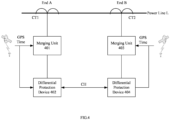
- FIG. 4 is a diagram of an example usage scenario of the time alignment method according to the embodiments of this disclosure.
- the substation automation systems employing process bus for communication are used at both end A and end B of the power line L.
- the current transformer CT1 is used as a process level device of the substation automation system, which measures the current analog values of end A.
- the merging unit 401 is an important part of the interface between the process level and the bay level of the substation automation system at end A.
- One side of the merging unit 401 is connected to the current transformer CT1 via the parallel cables to receive the current analog values measured by the current transformer CT1 and then processes the received current analog values into the current sampled value packets.
- the other side of the merging unit 401 is connected to the differential protection device 402 that is a bay level device via the process bus and transmits the current sampled value packets to the differential protection device 402.
- the current analog values of end B are measured by the current transformer CT2.
- the merging unit 403 receives the current analog values of end B from the current transformer CT2 via parallel cables, processes the current analog values into current sampled value packets and transmits the sampled value packets to the differential protection device 404 via the process bus.
- the merging unit 401 is introduced in the usage scenario of FIG. 4 and the transmission between the merging unit 401 and the differential protection device 402 does not rely on parallel cables but on the process bus, causing a large transmission delay that cannot be ignored for the differential protection.
- the transmission delay is unstable because the process bus may be subjected to various interference factors. If the differential protection devices 402 and 404 still use the time alignment method shown in FIG. 3 , there may be a deviation between the moment to which the current Fourier value is aligned and the moment of the acquisition of the current value corresponding to the current Fourier value.
- this disclosure proposes a time alignment method that can be applied to a substation automation system with a merging unit using a process bus for communication.
- the differential protection devices 402 and 404 in FIG. 4 perform the conversion of the sampled values into the time-aligned current Fourier values according to the time alignment method of the embodiments of this disclosure. After the differential protection devices 402 and 404 exchange the time-aligned current Fourier values generated by each other via the communication channel CH, they can make the correct differential protection decision based on the principle of differential protection shown in FIG. 1 .
- the merging units 401 and 403 and the differential protection devices 402 and 404 each include the satellite positioning module for receiving the reference time source from a time-giving system such as GPS, BDS, Galileo or GLONASS and the like and generating PPS signals, as previously described.
- a time-giving system such as GPS, BDS, Galileo or GLONASS and the like
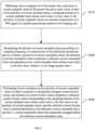
- FIG. 5 is the flowchart of the time alignment method according to embodiments of this disclosure.
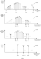
- FIG. 6 is the schematic diagram of the data transformation of the time alignment method according to embodiments of this disclosure.
- the time alignment method 500 includes steps S510 to S530.
- the time alignment method 500 may be performed by the differential protection device 402 and/or 404, as illustrated below with the differential protection device 402 as an example.
- the differential protection device 402 obtains a plurality of current sampled values of the power line L and a count value of each current sampled value from the merging unit 401.
- the sampling moment of a current sampled value whose count value is a first value in the plurality of current sampled values is a moment of generation of a PPS signal of a satellite positioning module of the merging unit 401.
- Illustration 610 in FIG. 6 shows one example of current sampled values obtained by sampling the current analog values measured by the current transformer CT1 by the merging unit 401.
- t ppsh , t ppsi , t ppsj and t ppsk indicate the moments of generation of the h-th PPS signal PPS h , the i-th PPS signal PPS i , the j-th PPS signal PPS j and the k-th PPS signal PPS k , respectively, generated successively by the satellite positioning module of the merging unit 401.
- the merging unit 401 samples N current sampled values per second.
- N there are N current sampled values X i,0 ⁇ X i,N-1 arranged between the generation moment t ppsi of the i-th PPS signal PPS i and the generation moment t ppsj of the j-th PPS signal PPS j , where X i,0 is the current sampled value sampled at the generation moment t ppsi of the i-th PPS signal PPS i .
- N is an integer greater than 1.
- the original current sampled values obtained by the merging unit 401 by sampling the current analog values may not include the current sampled values whose sampling moment happens to be the generation moments of t ppsh , t ppsi , t ppsj and t ppsk of the respective PPS signals.
- some current sampled values whose sampling moments are the generation moments t ppsh , t ppsi , t ppsj and t ppsk of the respective PPS signals are produced, as shown in illustration 610. Since interpolation is a technique well known in the art and to avoid obscuring this disclosure, this operation is not described in detail in this disclosure.
- the merging unit 401 transmits each sample value to the differential protection device 402 in the form of sampled value packet (e.g., conforming to standard IEC61850-9-2, etc.).
- Each sampled value packet is tagged with SmpCnt (hereinafter referred to as SC) indicating the count value of the sampled value.
- SC SmpCnt
- the count value is tagged in unit of the number of N current sampled values contained between the two generation moments of two consecutive PPS signals.
- the N current sample values contained between the two generation moments of two consecutive PPS signals are referred to as one set of current sampled values herein.
- the plurality of current sampled values includes at least one set of current sampled values, and the count values of the N current sampled values of each set of current sampled values are tagged from 0 to N-1 in chronological order, and the first value of the count value is 0.
- the horizontal axis represents the time of the merging unit 401
- the vertical axis represents the current sampled values obtained by the merging unit 401.
- the i-th set of current sampled values includes N current sampled values X i,0 ⁇ X i,3999 arranged between the generation moment t ppsi of the i-th PPS signal PPS i and the generation moment t ppsi of the j-th PPS signal PPSj, and their count values are SC i,0 ⁇ SC i,3999 , respectively.
- the j-th set of current sampled values after the i-th current sampled value includes the N current sampled values X j,0 ⁇ X j,3999 arranged between the generation time t ppsj of the j-th PPS signal PPSj and the generation time t ppsk of the k-th PPS signal PPS k , and their count values are SC j,0 ⁇ SC j,3999 , respectively.
- Illustration 620 in FIG. 6 shows an example of the current sampled values received by the differential protection device 402 from the merging unit 401.
- the horizontal axis of illustration 620 indicates the time of the differential protection unit 401 and the vertical axis indicates the current sampled value received by the differential protection unit 401.
- the differential protection device 402 receives the sampled value packet generated by the merging unit 401 via the process bus.
- a large transmission delay of the process bus results in, for example, the time distance ⁇ t i,delay between the moment ti,0 when the differential protection device 402 receives the current sampled value X i,0 whose count value is the first value SC i,0 in the i-th set of current sampled values and the generation moment t ppsi when the satellite positioning system of the differential protection device 402 generates the i-th PPS signal PPS i and the time distance ⁇ t j,delay between the moment t j,0 when the differential protection device 402 receives the current sampled value X j,0 whose count value is the first value SC j,0 in the j-th set of current sampled values and the generation moment t ppsj when the satellite positioning system of the differential protection device 402 generates the j-th PPS signal PPS j , and the like.
- the merging unit 401 can transmit the sampled value packet in real time, but the time distances ⁇ t i,delay and ⁇ t j,delay may be different, since the transmission delay of the process bus may be unstable due to the change of various interference factors over time.
- the differential protection device 402 resamples the plurality of current sampled values according to sampling frequency of J points/cycle (J is an integer greater than 1) to obtain the plurality of current resampled values.
- the plurality of current resampled values includes the reference current resampled values corresponding to the current sampled values whose count value is the first value in the plurality of current sampled values.
- the differential protection device 402 Since the sampling frequency of the differential protection device 402 is often different from the sampling frequency of the merging unit 401, the differential protection device 402 needs to resample multiple current sampled values.
- the resampling can be done by linear interpolation or other similar ways to produce M current resampling values per second. After resampling, the current resampled value corresponding to the current sampled value whose count value is the first value is used as the reference current resampled value.
- Illustration 630 in FIG. 6 is an example of the plurality of current resampled values obtained by the differential protection device 402 by resampling the current sampled values in illustration 620.
- the horizontal axis of illustration 630 indicates the time of the differential protection device 402 and the vertical axis indicates the current resampled values obtained by the differential protection device 401. Since the time duration for the resampling operation by the differential protection device 402 is negligible with respect to the calculation accuracy of the differential current, the time duration for the resampling operation by the differential protection device 401 is not considered in illustration 630.
- the M current resampled values corresponding to one set of current sampling values are referred to as one set of current resampled values herein.
- the plurality of resampled values obtained by the differential protection device 402 includes at least one set of current resampled values.
- At least one set of current resampled values as shown in illustration 630 corresponds to at least one set of current sampled values as shown in illustration 620 one by one.
- the first current resampling value in each set of current resampling values is used as the reference current resampled value.
- the i-th set of current resampled values includes 2400 current resampled values Y i,0 ⁇ Y i,2399 corresponding to the i-th set of current sampled values X i,0 ⁇ X i,3999 .
- the first current resampled value Yi,0 corresponds to the current sampled value X i,0 whose count value is the first value and thus is used as the reference current resampled value for the i-th set of current resampled values.
- the j-th set of current resampled values immediately after the i-th set of current sampled values includes 2400 current resampled values Y j,0 ⁇ Y j,2399 corresponding to the j-th set of current sampled values X j,0 ⁇ X j,3999 .
- the first current resampled value Y j,0 corresponds to the current sampled value X j,0 whose count value is the first value and thus is used as the reference current resampled value for the j-th set of current resampled values.
- the differential protection device 402 can resample the current sampling values more than once. For example, considering the demand for further noise reduction, filtering or reducing the amount of calculation, current sampled values may be resampled multiple times.
- step S530 Fourier transform is performed on the plurality of current resampled values to obtain a plurality of temporally arranged current Fourier values.
- the plurality of temporally arranged current Fourier values include the reference current Fourier value corresponding to the sampling moment of the current sampled value whose count value is the first value.
- the reference current Fourier value is determined based on the reference current resampled value and the J-1 current resampled values that temporally arranged before the reference current resampled value.
- the obtained plurality of temporally arranged current Fourier values may include at least one set of current Fourier values.
- the i-th set of current Fourier values including G temporally arranged current Fourier values DFT i,0 ⁇ DFT i,G-1 corresponding to the current resampled values Y i,0 ⁇ Y i,M-1 , respectively.
- DFT i,0 is the current Fourier value corresponding to the reference current resampled value Y i,0 and also corresponding to the current sampling value X i,0 whose count value is the first value and thus is used as the reference current Fourier value of the i-th set of current Fourier values.
- the j-th set of current Fourier value includes G temporally arranged current Fourier values DFT j,0 ⁇ DFT j,G-1 corresponding to the current resampled values Y j,0 ⁇ Y j,M-1 , respectively.
- DFT ji,0 is the current Fourier value corresponding to the reference current resampled value Y j,0 and also corresponding to the current sampled value X j,0 whose count value is the first value and thus is used as the reference current Fourier value of the j-th set of current Fourier values, and the like.
- Obtaining a plurality of current Fourier values by the differential protection device 402 includes obtaining each of the at least one set of current Fourier values.
- the first current Fourier value DFT i,0 in the i-th set of current Fourier values is obtained.
- the first current Fourier value DFT i,0 is obtained by taking the reference current resampled value Y i,0 of the i-th set of current resampled values and the 47 current resampled values temporally arranged before the reference current resampled value, i.e., Y h,2353 ⁇ Y i,0 , as transform objection and perform Fourier transform on the transform objection of Y h,2353 ⁇ Y i,0 .
- this first current Fourier value DFT i,0 corresponds to the reference current resampled value Y i,0 and the reference current resampled value Y i,0 corresponds to the current sampled value X i,0 whose count value is the first value
- this first current Fourier value DFT i,0 corresponds to the current sampled value X i,0 whose count value is the first value and thus is used as the reference current Fourier value of the i-th set of current Fourier values.
- the second current Fourier value DFT i,1 of the i-th set of current Fourier value is obtained.
- the second current Fourier value DFT i,1 is obtained by taking the 48 current resampled values Y h,2359 ⁇ Y i,6 as transform objection and performing Fourier transform on the transform objection of Y h,2359 ⁇ Y i,6 .
- the 48 current resampled values Y h,2359 ⁇ Y i,6 are obtained by moving 6 current resampled values backward in time from the 48 current resampled values Y h,2353 ⁇ Y i,0 .
- J is the sampling frequency of the last resampling.
- the first current Fourier values e.g., DFT i,0 , DFT j,0
- the reference current Fourier values corresponding to respective current sampling values whose count value are the first value e.g., X i,0 , X j,0 , respectively.
- the respective current sampling values whose count value , e.g., X i,0 , X j,0 , are the first value corresponds to the respective generation moments, e.g., t PPSi , t PPSi , of the PPS signals, e.g., PPS i , PPS j , of the satellite positioning module of the merging unit. Therefore, the respective first current Fourier values, e.g., DFT i,0 , DFT j,0 , as the reference current Fourier values, are aligned with the respective generation moments of the corresponding PPS signals, e.g., PPS i , PPS j .
- the time alignment method may further include step 540 of tagging each of the plurality of obtained current Fourier values with the moment for use in differential current calculation by an external device.
- the external device may be, for example, a differential protection device 404 at the other end of the power line L or another device that collects current information for both end A and end B of the power line L.
- Tagging each of the plurality of obtained current Fourier values with moment includes tagging respective current Fourier values of each set of current Fourier values with respective time-aligned moments.
- the reference current Fourier value in the i-th set of current Fourier values is tagged with the moment.
- the respective first current Fourier values DFT i,0 and DFT j,0 as the reference current Fourier values, are aligned with the respective generation moments of the corresponding PPS signals PPS i and PPS j , respectively. Therefore, as shown in illustration 640, The first current Fourier value (i.e., the reference current Fourier value) in the i-th set of current Fourier values is tagged with the generation moment t PPSi of the PPS signal PPS i corresponding to the first current Fourier value.
- each of the second to G-th current Fourier values in the i-th set of current Fourier values is tagged with the corresponding moment.
- the time distances ⁇ t i,delay and ⁇ t j,delay in illustration 620 may be different due to the unstable transmission delay between the merging unit 401 and the differential protection unit 402, which may result in a different number G of current Fourier values in different current Fourier sets.
- the time distances ⁇ t i,delay and ⁇ t j,delay may be different.
- the time distance between the two reception moments at which the two adjacent current sampled values whose count value are the first value in two adjacent sets of current sampled values are received by the differential protection device 402, e.g., the time distance between tj,0 and ti,0 is not always equal to 1 second.
- the time distance between tj,0 and ti,0 is greater than 1s when ⁇ t j,delay > ⁇ t i,delay and is less than 1s when ⁇ t j,delay ⁇ t i,delay , which may cause different number G of current Fourier values in the different set of current Fourier values.
- the differential protection device 402 calculates the first Fourier value DFTi,0 in the i-th set of current Fourier values at the moment t i,0 , and then calculates the second Fourier value DFT i,1 , and the like, until the DFT i,399 is calculated.
- the differential protection device 402 waits for the arrival of moment t j,0 to calculate the first Fourier value DFT j,0 in the j-th set of current Fourier values.
- the differential protection device 402 receives the current sample value whose current is the first value in the j-th set of the current Fourier values before calculating the last one or more current Fourier values in the i-th set of current Fourier values.
- the differential protection device 402 stops calculating the last one or more current Fourier values in the i-th set of current Fourier and to immediately calculate the first current Fourier value DFT j,0 in the j-th set of current Fourier values.
- the number G of current Fourier values in the i-th set of current Fourier is less than 400, G ⁇ 400.
- the differential protection apparatus 402 using the above-described time alignment method according to embodiments of this disclosure may obtain current information I1 of end A of the power line L.
- the current information I1 includes the current Fourier values of end A tagged with the time-aligned moments. This current information may be sent to an external device for use in calculating the differential current of the power line L.
- FIG. 7 is a diagram of another example usage scenario for the time alignment method according to an embodiment of this disclosure.
- the above-described time alignment method 500 is also applicable to the scenario shown in FIG. 7 .
- end A of power line L has the same arrangement as end A of FIG. 4
- end B has the same arrangement as end B of FIG. 2 .
- Differential protection device 402 at end A performs the time alignment method 500 according to the presently disclosed embodiment to obtain the time aligned current information I1 at end A.
- the time aligned current information I1 includes the current Fourier values of the current tagged with the aligned moment at end A.
- Differential protection device R2 at end B performs the time alignment method 500 according to the prior art as described above in connection with FIG. 2 to obtain the time aligned current information I2 at end B.
- the time aligned current information I2 includes the current Fourier values of the current tagged with the aligned moment at the B.
- the differential protection devices 402 and R2 are able to calculate the differential current of the power line L and thus make a correct differential protection decision based on the differential protection principle shown in FIG. 1 .
- FIG. 8 is a schematic block diagram of a differential protection device according to an embodiment of this disclosure.
- the differential protection device 800 (e.g., differential protection devices 401, 402 in FIG. 4 ) according to an embodiment of this disclosure includes a communication module 801, a sampling module 802 and a time alignment module 803.
- the communication module 801 is configured to obtain a plurality of current sampled values of the power line L from the merging unit of the power line L and the count value of each of the plurality of current sampled values.
- the respective sampling moments of the respective current sampled values whose count value are the first value in the plurality of current sampled values are the respective generation moments of the respective PPS signals generated by the first satellite positioning system module of the merging unit.
- the sampling module 802 is configured to resample a plurality of current sampling values according to the sampling frequency J points/cycle of the differential protection device to obtain a plurality of current resampled values.
- the plurality of current resampled values includes the reference current resampled values corresponding to the current sampled values whose count values are the first value in the plurality of current sampling values.
- the time alignment module 803 is configured to perform Fourier transform on the plurality of current resample values to obtain a temporally arranged plurality of current Fourier values.
- the plurality of current Fourier values includes respective reference current Fourier values corresponding to the respective sampling moments of the respective current sample values whose count values are the first value.
- the respective reference current Fourier values are determined based on the respective reference current resample value and the J-1 current resample values temporally arranged before the reference current resample value.
- the differential protection device 402 may include a satellite positioning module 804 (not shown) for receiving a reference time source from the time-giving system and generating a PPS signal.
- a satellite positioning module 804 (not shown) for receiving a reference time source from the time-giving system and generating a PPS signal.
- FIG. 9 is a schematic block diagram of a differential protection system 900 according to embodiments of this disclosure.
- the differential protection system 900 includes a current transformer such as the current transformers CT1 and CT2 shown in FIG. 2 , FIG. 4 , and FIG. 7 , a merging unit such as the merging unit 401 and 403 shown in FIG. 4 and FIG. 7 , and a differential protection device such as the differential protection device 800 shown in FIG. 8 .
- the current transformer is used to measure the current analog values of the power line.
- the merging unit is used to generate a plurality of original current sampled values by sampling the current analog values, obtain a plurality of current sampled values by interpolating the plurality of original current sampled values, and tag each of the plurality of current sampled values with a count value.
- the sampling moment of the current sampled value whose count value is the first value in the plurality of current sampled values is the generation moment of a PPS signal generated by the satellite positioning module of the merging unit.
- the differential protection device e.g., the differential protection device 800, obtains the plurality of current sampled values of the power line and the count value of each of the plurality of current sampled values from the merging unit of the power line.
- the sampling moment of the current sampled value whose count value is the first value in the plurality of current sampled values is the generation moment of a PPS signal generated by the satellite positioning module of the merging unit.
- the differential protection device further resamples the plurality of current sampled values according to a sampling frequency of J points/cycle to obtain a plurality of current resampled values.
- the plurality of current resampled values include the reference current resampled value corresponding to the current sampled values whose count value are the first value.
- the differential protection device further performs Fourier transform on the plurality of current resampled values to obtain a plurality of temporally arranged current Fourier values.
- the plurality of current Fourier values include the reference current Fourier value corresponding to the sampling moment of the current sampled value whose count value is the first value in the plurality of current sampled values.
- the reference current Fourier value is determined based on the reference current resampled value and the J-1 current resampled values that temporally arranged before the reference current resampled value.
Landscapes
- Engineering & Computer Science (AREA)
- Computer Networks & Wireless Communication (AREA)
- Physics & Mathematics (AREA)
- General Physics & Mathematics (AREA)
- Power Engineering (AREA)
- Signal Processing (AREA)
- Artificial Intelligence (AREA)
- Evolutionary Computation (AREA)
- Emergency Protection Circuit Devices (AREA)
Applications Claiming Priority (1)
| Application Number | Priority Date | Filing Date | Title |
|---|---|---|---|
| CN202210113257.2A CN116566530B (zh) | 2022-01-30 | 2022-01-30 | 差动保护装置的对时方法、差动保护装置和差动保护系统 |
Publications (3)
| Publication Number | Publication Date |
|---|---|
| EP4220879A1 true EP4220879A1 (fr) | 2023-08-02 |
| EP4220879C0 EP4220879C0 (fr) | 2024-10-23 |
| EP4220879B1 EP4220879B1 (fr) | 2024-10-23 |
Family
ID=85285255
Family Applications (1)
| Application Number | Title | Priority Date | Filing Date |
|---|---|---|---|
| EP23305113.5A Active EP4220879B1 (fr) | 2022-01-30 | 2023-01-30 | Procédé d'alignement temporel de dispositif de protection différentielle, dispositif de protection différentielle et système de protection différentielle |
Country Status (3)
| Country | Link |
|---|---|
| US (1) | US20230243875A1 (fr) |
| EP (1) | EP4220879B1 (fr) |
| CN (1) | CN116566530B (fr) |
Citations (1)
| Publication number | Priority date | Publication date | Assignee | Title |
|---|---|---|---|---|
| US20160329975A1 (en) * | 2014-01-22 | 2016-11-10 | Siemens Aktiengesellschaft | Digital measurement input for an electric automation device, electric automation device comprising a digital measurement input, and method for processing digital input measurement values |
Family Cites Families (6)
| Publication number | Priority date | Publication date | Assignee | Title |
|---|---|---|---|---|
| KR101108683B1 (ko) * | 2010-09-29 | 2012-01-30 | 한국전력공사 | 프로세스 버스 기반의 차동보호계전 lED의 위상각 차 보상장치 및 방법 |
| EP3159990B1 (fr) * | 2015-10-22 | 2018-01-31 | General Electric Technology GmbH | Améliorations de ou associées à des systèmes de génération d'électricite |
| US11128481B2 (en) * | 2018-10-08 | 2021-09-21 | Schweitzer Engineering Laboratories, Inc. | Hardware accelerated communication frame |
| CN109387697B (zh) * | 2018-11-20 | 2024-08-02 | 国网甘肃省电力公司电力科学研究院 | 无线相位测量装置、时间同步方法及无线相位测量方法 |
| CN112600179B (zh) * | 2020-12-31 | 2022-12-27 | 南京智汇电力技术有限公司 | 一种适用于5g无线通信的差动同步方法及系统 |
| US20230143318A1 (en) * | 2021-11-09 | 2023-05-11 | Landis+Gyr Innovations, Inc. | Sampling rate converter with line frequency and phase locked loops for energy metering |
-
2022
- 2022-01-30 CN CN202210113257.2A patent/CN116566530B/zh active Active
-
2023
- 2023-01-30 EP EP23305113.5A patent/EP4220879B1/fr active Active
- 2023-01-30 US US18/102,891 patent/US20230243875A1/en active Pending
Patent Citations (1)
| Publication number | Priority date | Publication date | Assignee | Title |
|---|---|---|---|---|
| US20160329975A1 (en) * | 2014-01-22 | 2016-11-10 | Siemens Aktiengesellschaft | Digital measurement input for an electric automation device, electric automation device comprising a digital measurement input, and method for processing digital input measurement values |
Non-Patent Citations (3)
| Title |
|---|
| ADRAH CHARLES M ET AL: "A Methodology to Implement and Investigate Performance of Sampled Values for Wide-Area Protection", 2018 2ND INTERNATIONAL CONFERENCE ON SMART GRID AND SMART CITIES (ICSGSC), IEEE, 12 August 2018 (2018-08-12), pages 84 - 90, XP033450701, DOI: 10.1109/ICSGSC.2018.8541290 * |
| CHEN XI ET AL: "Interoperability Performance Assessment of Multivendor IEC61850 Process Bus", IEEE TRANSACTIONS ON POWER DELIVERY, IEEE SERVICE CENTER, NEW YORK, NY, US, vol. 31, no. 4, 1 August 2016 (2016-08-01), pages 1934 - 1944, XP011617616, ISSN: 0885-8977, [retrieved on 20160721], DOI: 10.1109/TPWRD.2015.2509644 * |
| ZHONGQING LI ET AL: "Sampled data synchronization scheme for relay protection in smart substation", 2014 INTERNATIONAL CONFERENCE ON POWER SYSTEM TECHNOLOGY, IEEE, 20 October 2014 (2014-10-20), pages 1778 - 1784, XP032712057, DOI: 10.1109/POWERCON.2014.6993613 * |
Also Published As
| Publication number | Publication date |
|---|---|
| CN116566530B (zh) | 2025-08-26 |
| EP4220879C0 (fr) | 2024-10-23 |
| EP4220879B1 (fr) | 2024-10-23 |
| US20230243875A1 (en) | 2023-08-03 |
| CN116566530A (zh) | 2023-08-08 |
Similar Documents
| Publication | Publication Date | Title |
|---|---|---|
| US10228409B2 (en) | Fault location using traveling waves | |
| US10581237B2 (en) | High-frequency electric power system signal processing system | |
| US10656198B2 (en) | Electric power system monitoring using high-frequency signals | |
| US11307264B2 (en) | Phase selection for traveling wave fault detection systems | |
| CN101383495B (zh) | 广域保护控制测量系统和方法 | |
| CN101710158B (zh) | 具有高压电力设备绝缘在线监测功能的变电站自动化系统 | |
| EP4047444A1 (fr) | Système et procédé de détection d'injection de fausses données dans des sous-stations électriques | |
| US10564246B2 (en) | Testing system for traveling wave fault detectors | |
| EP2562554A2 (fr) | Système et procédé dýidentification de phase | |
| JP2010019625A (ja) | 事故点標定方法および事故点標定装置 | |
| CN103995181A (zh) | 一种数字化变电站电能质量谐波分析方法 | |
| CN117572320A (zh) | 一种配电终端波形采集时间同步性校正方法 | |
| EP4220879A1 (fr) | Procédé d'alignement temporel de dispositif de protection différentielle, dispositif de protection différentielle et système de protection différentielle | |
| US20190369156A1 (en) | Travelling wave based method for locating a fault in a transmission line and device therefor | |
| Rodrigues et al. | A Phasor Measurement Unit based on discrete fourier transform using digital signal processor | |
| Dutra et al. | Comparison of analogue measurements between merging units and conventional acquisition systems | |
| EP3018782B1 (fr) | Dispositif de relais de protection | |
| KR102641615B1 (ko) | 고장 거리 검출이 가능한 다기능 위상 측정 장치 | |
| US20240192255A1 (en) | System for variably controlling sampling frequency | |
| Qiangsheng et al. | Research on synchronization test method for distributed sampling data based on precise time-setting | |
| Xiao et al. | Synchronization method based on FPGA for merging unit of the electronic transformers | |
| Aredes et al. | A SCADA system to analyze harmonic currents propagation | |
| Zhao et al. | A localized synchrophasor measurement system | |
| JP2000065879A (ja) | 送電線用故障点標定装置 | |
| NZ601881B (en) | Phase identification system and method |
Legal Events
| Date | Code | Title | Description |
|---|---|---|---|
| PUAI | Public reference made under article 153(3) epc to a published international application that has entered the european phase |
Free format text: ORIGINAL CODE: 0009012 |
|
| STAA | Information on the status of an ep patent application or granted ep patent |
Free format text: STATUS: THE APPLICATION HAS BEEN PUBLISHED |
|
| AK | Designated contracting states |
Kind code of ref document: A1 Designated state(s): AL AT BE BG CH CY CZ DE DK EE ES FI FR GB GR HR HU IE IS IT LI LT LU LV MC ME MK MT NL NO PL PT RO RS SE SI SK SM TR |
|
| STAA | Information on the status of an ep patent application or granted ep patent |
Free format text: STATUS: REQUEST FOR EXAMINATION WAS MADE |
|
| 17P | Request for examination filed |
Effective date: 20240103 |
|
| RBV | Designated contracting states (corrected) |
Designated state(s): AL AT BE BG CH CY CZ DE DK EE ES FI FR GB GR HR HU IE IS IT LI LT LU LV MC ME MK MT NL NO PL PT RO RS SE SI SK SM TR |
|
| GRAP | Despatch of communication of intention to grant a patent |
Free format text: ORIGINAL CODE: EPIDOSNIGR1 |
|
| STAA | Information on the status of an ep patent application or granted ep patent |
Free format text: STATUS: GRANT OF PATENT IS INTENDED |
|
| INTG | Intention to grant announced |
Effective date: 20240517 |
|
| GRAS | Grant fee paid |
Free format text: ORIGINAL CODE: EPIDOSNIGR3 |
|
| GRAA | (expected) grant |
Free format text: ORIGINAL CODE: 0009210 |
|
| STAA | Information on the status of an ep patent application or granted ep patent |
Free format text: STATUS: THE PATENT HAS BEEN GRANTED |
|
| AK | Designated contracting states |
Kind code of ref document: B1 Designated state(s): AL AT BE BG CH CY CZ DE DK EE ES FI FR GB GR HR HU IE IS IT LI LT LU LV MC ME MK MT NL NO PL PT RO RS SE SI SK SM TR |
|
| REG | Reference to a national code |
Ref country code: GB Ref legal event code: FG4D |
|
| REG | Reference to a national code |
Ref country code: CH Ref legal event code: EP |
|
| REG | Reference to a national code |
Ref country code: DE Ref legal event code: R096 Ref document number: 602023000820 Country of ref document: DE |
|
| REG | Reference to a national code |
Ref country code: IE Ref legal event code: FG4D |
|
| U01 | Request for unitary effect filed |
Effective date: 20241023 |
|
| U07 | Unitary effect registered |
Designated state(s): AT BE BG DE DK EE FI FR IT LT LU LV MT NL PT RO SE SI Effective date: 20241029 |
|
| U20 | Renewal fee for the european patent with unitary effect paid |
Year of fee payment: 3 Effective date: 20250127 |
|
| PG25 | Lapsed in a contracting state [announced via postgrant information from national office to epo] |
Ref country code: HR Free format text: LAPSE BECAUSE OF FAILURE TO SUBMIT A TRANSLATION OF THE DESCRIPTION OR TO PAY THE FEE WITHIN THE PRESCRIBED TIME-LIMIT Effective date: 20241023 Ref country code: IS Free format text: LAPSE BECAUSE OF FAILURE TO SUBMIT A TRANSLATION OF THE DESCRIPTION OR TO PAY THE FEE WITHIN THE PRESCRIBED TIME-LIMIT Effective date: 20250223 |
|
| PG25 | Lapsed in a contracting state [announced via postgrant information from national office to epo] |
Ref country code: ES Free format text: LAPSE BECAUSE OF FAILURE TO SUBMIT A TRANSLATION OF THE DESCRIPTION OR TO PAY THE FEE WITHIN THE PRESCRIBED TIME-LIMIT Effective date: 20241023 |
|
| PG25 | Lapsed in a contracting state [announced via postgrant information from national office to epo] |
Ref country code: NO Free format text: LAPSE BECAUSE OF FAILURE TO SUBMIT A TRANSLATION OF THE DESCRIPTION OR TO PAY THE FEE WITHIN THE PRESCRIBED TIME-LIMIT Effective date: 20250123 |
|
| PG25 | Lapsed in a contracting state [announced via postgrant information from national office to epo] |
Ref country code: GR Free format text: LAPSE BECAUSE OF FAILURE TO SUBMIT A TRANSLATION OF THE DESCRIPTION OR TO PAY THE FEE WITHIN THE PRESCRIBED TIME-LIMIT Effective date: 20250124 |
|
| PG25 | Lapsed in a contracting state [announced via postgrant information from national office to epo] |
Ref country code: PL Free format text: LAPSE BECAUSE OF FAILURE TO SUBMIT A TRANSLATION OF THE DESCRIPTION OR TO PAY THE FEE WITHIN THE PRESCRIBED TIME-LIMIT Effective date: 20241023 |
|
| PG25 | Lapsed in a contracting state [announced via postgrant information from national office to epo] |
Ref country code: RS Free format text: LAPSE BECAUSE OF FAILURE TO SUBMIT A TRANSLATION OF THE DESCRIPTION OR TO PAY THE FEE WITHIN THE PRESCRIBED TIME-LIMIT Effective date: 20250123 |
|
| PG25 | Lapsed in a contracting state [announced via postgrant information from national office to epo] |
Ref country code: SM Free format text: LAPSE BECAUSE OF FAILURE TO SUBMIT A TRANSLATION OF THE DESCRIPTION OR TO PAY THE FEE WITHIN THE PRESCRIBED TIME-LIMIT Effective date: 20241023 |
|
| PG25 | Lapsed in a contracting state [announced via postgrant information from national office to epo] |
Ref country code: SK Free format text: LAPSE BECAUSE OF FAILURE TO SUBMIT A TRANSLATION OF THE DESCRIPTION OR TO PAY THE FEE WITHIN THE PRESCRIBED TIME-LIMIT Effective date: 20241023 |
|
| PG25 | Lapsed in a contracting state [announced via postgrant information from national office to epo] |
Ref country code: CZ Free format text: LAPSE BECAUSE OF FAILURE TO SUBMIT A TRANSLATION OF THE DESCRIPTION OR TO PAY THE FEE WITHIN THE PRESCRIBED TIME-LIMIT Effective date: 20241023 |
|
| PLBE | No opposition filed within time limit |
Free format text: ORIGINAL CODE: 0009261 |
|
| STAA | Information on the status of an ep patent application or granted ep patent |
Free format text: STATUS: NO OPPOSITION FILED WITHIN TIME LIMIT |
|
| PG25 | Lapsed in a contracting state [announced via postgrant information from national office to epo] |
Ref country code: MC Free format text: LAPSE BECAUSE OF FAILURE TO SUBMIT A TRANSLATION OF THE DESCRIPTION OR TO PAY THE FEE WITHIN THE PRESCRIBED TIME-LIMIT Effective date: 20241023 |
|
| 26N | No opposition filed |
Effective date: 20250724 |
|
| PG25 | Lapsed in a contracting state [announced via postgrant information from national office to epo] |
Ref country code: IE Free format text: LAPSE BECAUSE OF NON-PAYMENT OF DUE FEES Effective date: 20250130 |
|
| U20 | Renewal fee for the european patent with unitary effect paid |
Year of fee payment: 4 Effective date: 20260126 |