EP4220902A1 - Verfahren und vorrichtung zur kühlung einer rotoranordnung - Google Patents
Verfahren und vorrichtung zur kühlung einer rotoranordnung Download PDFInfo
- Publication number
- EP4220902A1 EP4220902A1 EP23152096.6A EP23152096A EP4220902A1 EP 4220902 A1 EP4220902 A1 EP 4220902A1 EP 23152096 A EP23152096 A EP 23152096A EP 4220902 A1 EP4220902 A1 EP 4220902A1
- Authority
- EP
- European Patent Office
- Prior art keywords
- rotor
- coolant
- radially
- outer portion
- coil support
- Prior art date
- Legal status (The legal status is an assumption and is not a legal conclusion. Google has not performed a legal analysis and makes no representation as to the accuracy of the status listed.)
- Pending
Links
Images




Classifications
-
- H—ELECTRICITY
- H02—GENERATION; CONVERSION OR DISTRIBUTION OF ELECTRIC POWER
- H02K—DYNAMO-ELECTRIC MACHINES
- H02K3/00—Details of windings
- H02K3/46—Fastening of windings on the stator or rotor structure
- H02K3/50—Fastening of winding heads, equalising connectors, or connections thereto
- H02K3/51—Fastening of winding heads, equalising connectors, or connections thereto applicable to rotors only
-
- H—ELECTRICITY
- H02—GENERATION; CONVERSION OR DISTRIBUTION OF ELECTRIC POWER
- H02K—DYNAMO-ELECTRIC MACHINES
- H02K3/00—Details of windings
- H02K3/04—Windings characterised by the conductor shape, form or construction, e.g. with bar conductors
- H02K3/24—Windings characterised by the conductor shape, form or construction, e.g. with bar conductors with channels or ducts for cooling medium between the conductors
-
- H—ELECTRICITY
- H02—GENERATION; CONVERSION OR DISTRIBUTION OF ELECTRIC POWER
- H02K—DYNAMO-ELECTRIC MACHINES
- H02K1/00—Details of the magnetic circuit
- H02K1/06—Details of the magnetic circuit characterised by the shape, form or construction
- H02K1/22—Rotating parts of the magnetic circuit
- H02K1/28—Means for mounting or fastening rotating magnetic parts on to, or to, the rotor structures
-
- H—ELECTRICITY
- H02—GENERATION; CONVERSION OR DISTRIBUTION OF ELECTRIC POWER
- H02K—DYNAMO-ELECTRIC MACHINES
- H02K1/00—Details of the magnetic circuit
- H02K1/06—Details of the magnetic circuit characterised by the shape, form or construction
- H02K1/22—Rotating parts of the magnetic circuit
- H02K1/32—Rotating parts of the magnetic circuit with channels or ducts for flow of cooling medium
-
- H—ELECTRICITY
- H02—GENERATION; CONVERSION OR DISTRIBUTION OF ELECTRIC POWER
- H02K—DYNAMO-ELECTRIC MACHINES
- H02K9/00—Arrangements for cooling or ventilating
- H02K9/19—Arrangements for cooling or ventilating for machines with closed casing and closed-circuit cooling using a liquid cooling medium, e.g. oil
-
- H—ELECTRICITY
- H02—GENERATION; CONVERSION OR DISTRIBUTION OF ELECTRIC POWER
- H02K—DYNAMO-ELECTRIC MACHINES
- H02K7/00—Arrangements for handling mechanical energy structurally associated with dynamo-electric machines, e.g. structural association with mechanical driving motors or auxiliary dynamo-electric machines
- H02K7/18—Structural association of electric generators with mechanical driving motors, e.g. with turbines
- H02K7/1807—Rotary generators
- H02K7/1823—Rotary generators structurally associated with turbines or similar engines
Definitions
- Electric machines such as electric motors or electric generators, are used in energy conversion. Such electrical machines operate through the interaction of magnetic fields, and current carrying conductors generate the force or electricity respectively.
- an electrical motor converts electrical energy into mechanical energy.
- an electrical generator converts mechanical energy into electrical energy.
- an electric machine typically includes a rotor having rotor windings that are driven to rotate by a source of rotation, such as a mechanical or electrical machine, which for some aircraft may be a gas turbine engine.
- a source of rotation such as a mechanical or electrical machine, which for some aircraft may be a gas turbine engine.
- Heat is generated in the rotor due to the flow of current through the windings, and changing magnetic fields present in the rotor, causing the temperature to rise in the rotor. It is desirable to cool the rotor to protect the electrical machine from damage and to increase the electrical machine power density to allow for more power from a smaller physically sized electric motor.
- aspects of the disclosure can be implemented in any environment using an electric motor regardless of whether the electric motor provides a driving force or generates electricity.
- an electric motor will be generally referred to as an electric machine, electric machine assembly, or similar language, which is meant to clarify that one or more stator/rotor combinations can be included in the machine. While this description is primarily directed toward an electric machine providing power generation, it is also applicable to an electric machine providing a driving force or an electric machine providing both a driving force and power generation. Further, while this description is primarily directed toward an aircraft environment, aspects of the disclosure are applicable in any environment using an electric machine. Thus, a brief summary of a contemplated environment should aid in a more complete understanding.
- axial refers to a dimension along a longitudinal axis of a generator or along a longitudinal axis of a component disposed within the generator.
- radial refers to a dimension extending between a center longitudinal axis, an outer circumference, or a circular or annular component disposed thereof.
- proximal refers to moving in a direction toward the center longitudinal axis, or a component being relatively closer to the center longitudinal axis as compared to another component.
- a "wet” cavity generator includes a cavity housing the rotor and stator that is exposed to free liquid coolant (e.g. coolant freely moving within the cavity).
- a “dry” cavity generator the rotor and stator can be cooled by coolant contained within limited in fluidly sealed passages (e.g. non-freely moving about the cavity).
- FIG. 1 illustrates a gas turbine engine 10 having an accessory gear box (AGB) 12 and an electric machine or generator 14 according to an aspect of the disclosure.
- the gas turbine engine 10 can be a turbofan engine, such as a General Electric GEnx or CF6 series engine, commonly used in modern commercial and military aviation or it could be a variety of other known gas turbine engines such as a turboprop or turboshaft.
- the AGB 12 can be coupled to a turbine shaft (not shown) of the gas turbine engine 10 by way of a mechanical power take off 16.
- the gas turbine engine 10 can be any suitable gas turbine engine used in modern aviation or it could be a variety of other known gas turbine engines such as a turboprop or turboshaft.
- gas turbine engine 10 The type and specifics of the gas turbine engine 10 are not germane to the disclosure and will not be described further herein. While a generator 14 is shown and described, aspects of the disclosure are not so limited, and aspects can include any electromotive or electrical machine, such as, without limitation, a motor, or generator.
- FIG. 2 more clearly illustrates a non-limiting example of generator 14 and its housing 18 in accordance with aspects of the disclosure.
- the generator 14 can include a clamping interface 20, used to clamp the generator 14 to the AGB (not shown). Multiple electrical connections can be provided on the exterior of the generator 14 to provide for the transfer of electrical power to and from the generator 14. The electrical connections can be further connected by cables to an electrical power distribution node of an aircraft having the gas turbine engine 10 to power various items on the aircraft, such as lights and seat-back monitors.
- the generator 14 can include a liquid coolant system for cooling or dissipating heat generated by components of the generator 14 or by components proximate to the generator 14, one non-limiting example of which can be the gas turbine engine 10.
- the generator 14 can include a liquid cooling system using oil as a coolant.
- the liquid cooling system can include a cooling fluid inlet port 82 and a cooling fluid outlet port 84 for controlling the supply of coolant to the generator 14.
- the cooling fluid inlet and output ports 82, 84 can be utilized for cooling at least a portion of a rotor or stator of the generator 14.
- the liquid cooling system can also include a second coolant outlet port 91, shown at a rotatable shaft portion of the generator 14.
- the liquid cooling system can include a rotatable shaft coolant inlet port 94 or a generator coolant outlet port 95.
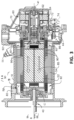
- FIG. 3 is a cross-sectional view of the generator 14 shown in FIG. 2 taken along line III-III.
- a rotatable shaft 40 is located within the generator 14 and is the primary structure for supporting a variety of components.
- the rotatable shaft 40 can have a single diameter or one that can vary along its length.
- the rotatable shaft 40 is supported by spaced bearings 42 and 44 and configured to rotate about a rotational axis 41.
- Several of the elements of the generator 14 have a fixed component and a rotating component, with the fixed component fixed relative to the housing 18 and with the rotating component being provided on, or rotatably fixed relative to the rotatable shaft 40.
- Examples of these elements can include a main machine 50, housed within a main machine cavity 51, an exciter 60, and a permanent magnet generator (PMG) 70.
- the corresponding rotating component comprises a main machine rotor 52, an exciter rotor 62, and a PMG rotor 72, respectively, and the corresponding fixed component comprises a main machine stator 54 or stator core, an exciter stator 64, and a PMG stator 74.
- the main machine rotor 52, exciter rotor 62, and PMG rotor 72 are disposed on and co-rotate with the rotatable shaft 40.
- the fixed components can be mounted to any suitable part of the housing 18, and include the main machine stator 54, exciter stator 64, and PMG stator 74. Collectively, the fixed components define an interior through which the rotatable shaft 40 extends and rotates relative thereto.
- main machine rotor 52, exciter rotor 62, and PMG rotor 72 can have a set of rotor poles
- main machine stator 54, exciter stator 64, and PMG stator 74 can have a set of stator poles.
- the set of rotor poles can generate a set of magnetic fields relative to the set of stator poles, such that the rotation of the rotor magnetic fields relative to the stator poles generate current in the respective stator components.
- At least one of the rotor poles and stator poles can be formed by a core with a post and wire wound about the post to form a winding, with the winding having at least one end turn.
- Aspects of the disclosure shown include at least one set of stator windings 90 arranged longitudinally along the housing 18, that is, in parallel with housing 18 and the rotational axis 41.
- the set of stator windings 90 can also include a set of stator winding end turns 92 extending axially beyond opposing ends of a longitudinal length of a main machine stator 54.
- the components of the generator 14 can be any combination of known generators.
- the main machine 50 can be either a synchronous or asynchronous generator.
- there can be other accessories driven from the same rotatable shaft 40 such as the liquid coolant pump, a fluid compressor, or a hydraulic pump.
- the generator 14 can be oil cooled and thus can include a cooling system 80.
- the cooling oil can be used to dissipate heat generated by the electrical and mechanical functions of the generator 14.
- the cooling system 80 using oil can also provide for lubrication of the generator 14.
- the generator 14 can be a liquid cooled, wet cavity type cooling system 80 including the cooling fluid inlet port 82 and the cooling fluid outlet port 84 for controlling the supply of the cooling fluid to the cooling system 80.
- the cooling system 80 can further include, for example, a cooling fluid reservoir 86 and various cooling passages.
- the rotatable shaft 40 can provide one or more channels or paths for coolant or fluid coolant flow 85 (shown schematically as arrows) for the main machine rotor 52, exciter rotor 62, and PMG rotor 72, as well as a rotor shaft cooling fluid outlet 88, such as the second coolant outlet port 91, wherein residual, unused, or unspent oil can be discharged from the rotatable shaft 40.
- the fluid coolant flow 85 can further be directed, exposed, sprayed, or otherwise deposited onto the set of stator windings 90, the set of stator winding end turns 92, or onto alternative or additional components.
- the fluid coolant flow 85 can flow from the rotatable shaft 40 radially outward toward the set of stator windings 90 or the set of stator winding end turns 92. In this sense, the coolant can cool the respective set of stator windings 90 or set of stator winding end turns 92.
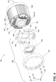
- FIG. 4 illustrates a partially exploded perspective view of a rotor assembly 96 such as for a main electrodynamic machine.
- the rotor assembly 96 can include a rotor core 100, such as a laminated rotor core, rotatably connected to co-rotate with the rotatable shaft 40.
- the rotor assembly 96 can include a set of coil support assemblies 130.
- Each coil support assembly 130 can respectively include a coil support disc 131 and a retaining ring 132.
- each coil support assembly 130 can further include a respective coolant spray ring 125.
- the rotor assembly 96 can further define a first end 102 and a second end 104, axially spaced from the first end 102.
- the rotor assembly 96 can include at least one rotor pole 106 defined by a rotor post 108 and formed when at least a portion of the rotor core 100 is wound with a conductive rotor wiring or rotor windings 110 about the rotor post 108.
- the rotor windings 110 wound around the rotor post 108 can define an axial winding portion 111 extending axially along the rotor core 100, and rotor winding end turns 112 extending axially beyond the rotor core 100.
- the rotor post 108 can underlie the set of rotor windings 110. While the rotor windings 110 or the rotor winding end turns 112 can refer to a set of or plural windings or end turns, an end turn can include only one of the set of rotor windings 110, or only one portion of the set of rotor windings 110 extending axially beyond the rotor core 100, such as only at the first end 102 or the second end 104.
- the set of rotor winding end turns 112 can define a respective loop or arcuate bight portion 113 disposed axially beyond the rotor core 100.
- each bight portion 113 can define a respective channel 116 extending therethrough.
- each respective channel 116 can have a width defined by a width of corresponding rotor post 108.
- the coil support assembly 130 can be disposed at either end 102, 104 of the rotor assembly 96.
- a single coil support assembly 130 can be disposed at one end of the rotor assembly 96.
- a respective coil support assembly 130 can be disposed at each end of the rotor assembly 96.
- a respective coil support assembly 130 can be fixedly coupled to each end of the rotatable shaft 40 of the rotor assembly 96.
- a respective coil support assembly 130 can be coupled to one end (e.g., either the first end 102 or the second end 104) of the rotor assembly 96.
- a respective coil support assembly 130 can be coupled to the rotatable shaft 40 at both the first end 102 and the second end 104 of the rotor assembly 96.
- the coil support disc 131 can comprise a radially inboard or central portion 133 and an outer portion 134 disposed radially outward from the central portion 133.
- the central portion 133 can define a bore 135 therethrough.
- the central portion 133 can be coupled to the outer portion 134 via a set of radially extending spokes 136.
- each spoke 136 can comprise a first end 138 coupled to the central portion 133, and an opposing second end 139 coupled to the outer portion 134.
- the spokes 136 can be circumferentially spaced from each other about the coil support disc 131.
- the number of spokes 136 can correspond to the number of rotor poles 106 of the rotor assembly 96.
- each spoke 136 can be operatively disposed between the rotor core 100 and a respective set of rotor winding end turns 112.
- each spoke 136 can be disposed within a respective channel 116 and extend therethrough.
- each set of rotor winding end turns 112 can be wound or wrapped at least partially about a respective spoke 136.
- the central portion 133 of the coil support disc 131 can at least partially underlie the rotor winding end turns 112. In this example, "underlie" denotes a relative position radially closer to the rotational axis 41.
- each spoke 136 can be at least partially surrounded by a respective set of rotor winding end turns 112 and provide support or limit a radial deflection or relative axial movement the respective set of rotor winding end turns 112.
- the number of spokes 136 of the coil support disc 131 can correspond to the number of rotor poles 106 of the rotor assembly 96.
- each respective spoke 136 can have a width defined by a width of a corresponding rotor post 108 ( FIG. 4 ).
- Other aspects are not so limited, and each respective spoke 136 can have a width that is narrower than a corresponding rotor post 108, or wider than a corresponding rotor post 108, without departing from the scope of the disclosure.
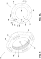
- FIG. 5 depicts a perspective view of an exemplary non-limiting aspect of the coolant spray ring 125
- FIG. 5A depicts another non-limiting aspect of the coolant spray ring 125 of FIG. 5 in an isometric front view.
- the coolant spray ring 125 can comprise an annular member having an inwardly facing, or radially inner surface 126 and an opposing outwardly facing, or radially outer surface 127.
- the radially inner surface 126 can define a bore 128 sized to receive the rotatable shaft 40 therethrough and to receive a flow of coolant therefrom.
- the radially inner surface 126 can operatively define a coolant collection surface.
- the radially inner surface 126 can be a relatively smooth surface.
- the radially inner surface 126 can define one or more channels or grooves 129 thereon. The grooves 129 can be arranged in fluid communication with the rotatable shaft 40. As such the one or more grooves 129 can operatively define a coolant reservoir.
- the coolant spray ring 125 can further include a set of coolant channels 187 defined therethrough.
- the coolant channels 187 can be sized to allow a flow of coolant fluid therethrough.
- the coolant channels 187 can be circumferentially spaced from each other about the coolant spray ring 125.
- Each coolant channel 187 can extend radially from a first end 187a at the radially inner surface 126 to an opposing second end 187b at the radially outer surface 127.
- Each coolant channel 187 can comprise a coolant inlet 188 defined on the radially inner surface 126, and a corresponding coolant outlet 189 defined on the radially outer surface 127, at the opposing second end 187b.
- the coolant channels 187 can be in fluid communication with the rotatable shaft 40, or the one or more grooves 129, or both, to receive the flow of coolant therefrom.
- Each coolant outlet 189 can comprise a respective spray nozzle 190.
- the spray nozzles 190 can be disposed at circumferentially spaced intervals on the radially outward surface 127.
- the coolant spray ring 125 can be fixed to the rotatable shaft 40 using one or more bolts, screws, pins, keys, or other known fasteners (not shown).
- the coolant spray ring 125 can be coupled to the rotatable shaft 40 via an interference, friction, or press-fit engagement between the coolant spray ring 125 and the rotatable shaft 40.
- Other aspects are not so limited, and it is contemplated that the coolant spray ring 125 can be rotatably coupled to the rotatable shaft 40 by any desired affixing mechanisms. It will be appreciated that when so coupled, a rotation of the rotatable shaft 40 will result in rotation of the coolant spray ring 125.
- the retaining ring 132 be disposed to surround the coil support disc 131.
- the retaining ring 132 can overlie or radially surround the coil support disc 131.
- the retaining ring 132 can be rigidly or fixedly coupled to the coil support disc 131.
- the retaining ring 132 can be coupled to the coil support disc 131 using bolts or other fasteners 118. When so coupled, the retaining ring and 132 can limit or arrest an axial movement of the coil support disc 131.
- the retaining ring 132 and coil support disc 131 can cooperatively limit a radial deflection or relative movement of the rotor winding end turns 112.
- FIG. 6 depicts a perspective view of exemplary non-limiting aspects of the coil support disc 131
- FIG. 6A depicts the coil support disc 131 of FIG. 6 and the retaining ring 132 in partial cut-away view along line A-A.
- FIGS. 6 and 6A depict a non-limiting example of the support disc 131 configured for a 4-pole rotor assembly 96
- other aspects are not so limited. It will be appreciated that aspects as disclosed herein are not limited to any specific number of rotor poles, and aspects can be adapted to rotor assemblies 96 having any desired number of poles.
- the outer portion 134 of the coil support disc 131 can comprise a set of elements or segments 137.
- the outer portion 134 can comprise a set of spaced apart segments 137.
- Each segment 137 can be coupled to a respective second end 139 of a corresponding spoke 136.
- the number of segments 137 can correspond to the number of rotor poles 106 of the rotor assembly 96.
- the segments 137 can define an arcuate shape. Other aspects are not so limited, and the segments 137 can define any desired shape without departing from the scope of the disclosure.
- Each segment 137 can comprise a respective outwardly facing, radially outer surface 144, and an opposing inwardly facing, radially inner surface 145.
- the radially inner surface 145 can underlie at least a portion of the radially outer surface 144.
- the outer portion 134 (e.g., the segments 137) can at least partially overlie the rotor winding end turns (not shown).
- "overlie” denotes a relative position radially farther from the rotational axis 41.
- each segment 137 can overlie a respective set of rotor winding end turns 112.
- the outer portion 134 of the support disc 131 can include a set of support disc channels 146 defined therethrough.
- the support disc channels 146 can be sized to allow flow of cooling fluid (e.g., oil) therethrough.
- each segment 137 can include one or more support disc channels 146.
- only a subset of the segments 137 can include one or more support disc channels 146.
- Each support disc channel 146 can comprise a coolant inlet 148 defined by a corresponding radially inner surface 145, and a coolant outlet 147 defined by a corresponding radially outer surface 144, at an opposing second end of the support disc channel 146.
- each support disc channel 146 can further define a fluid collection surface 149 disposed between the coolant inlet 148 and the coolant outlet 147.
- the one or more coolant inlets 148 of the coil support disc 131 can be coupled in fluid communication with a respective fluid collection surface 149 defined by a respective support disc channel 146.
- the fluid collection surface 149 can extend in an axial direction from the central portion 133.
- the coil support disc 131 can operatively receive the rotatable shaft 40 through the bore 135.
- the coil support disc 131 can be fixed to the rotatable shaft 40 using one or more bolts, screws, pins, keys, or other known fasteners.
- the coil support disc 131 can be coupled to the rotatable shaft 40 via an interference, friction, or press-fit engagement between the coil support disc 131 and the rotatable shaft 40.
- Other aspects are not so limited, and it is contemplated that the coil support disc 131 can be rotatably coupled to the rotatable shaft 40 by any desired affixing mechanisms. It will be appreciated that when so coupled, a rotation of the rotatable shaft 40 will result in rotation of the coil support disc 131.
- the retaining ring 132 can be disposed to surround the support disc 131.
- the retaining ring 132 can overlie or radially surround the coil support disc 131.
- the retaining ring 132 can be rigidly or fixedly coupled to the coil support disc 131.
- the retaining ring 132 can be coupled to the coil support disc 131 using bolts or other fasteners 118. When so coupled, the retaining ring 132 can limit or arrest an axial movement of the coil support disc 131.
- the retaining ring 132 and coil support disc 131 can cooperatively limit a radial deflection or relative movement of the rotor winding end turns 112.
- FIG. 7 illustrates a portion of the rotor assembly 96 of FIG. 4 for better understanding the cooling system 80 and fluid coolant flow 85 from the rotatable shaft 40 to the set of rotor winding end turns 112 and the set of stator winding end turns 92.
- the rotatable shaft 40 can define a first coolant conduit 150 fluidly connected with a source of coolant 152.
- the source of coolant 152 can be, but is not limited to the cooling fluid inlet port (not shown).
- the direction or location of the source of coolant 152 is not limited by the illustration and can be considered in any location that is fluidly coupled to the first coolant conduit 150. It is further considered that additional conduit, pumps, valves, or other devices can be included to fluidly connect the source of coolant 152 and the first coolant conduit 150.
- Fluid can enter the rotatable shaft 40 of the rotor assembly 96 via the inlet port 82.
- the rotatable shaft 40 at least in part, can define the first coolant conduit 150, through which fluid can flow radially outward from the rotational axis 41 due to the centrifugal force effects of the rotatable shaft 40.
- a first radial coolant passage 154 by way of extending radially through the rotatable shaft 40, can fluidly couple the first coolant conduit 150 and the coolant spray ring 125.
- the coolant spray ring 125 can receive the coolant fluid from the first radial coolant passage 154 via the radially inner surface 126.
- the coolant fluid can collect or accumulate in the one or more grooves 129 and then be centrifugally conveyed to the coolant channels 187, and to the corresponding coolant outlet 189.
- the coolant outlets e.g., spray nozzles 190
- spray nozzles 190 can be directed to provide a flow of coolant fluid flow 85 radially outwardly therefrom.
- the spray nozzles 190 can operatively spray finely atomized particles of coolant fluid toward the stator end turns using conventional atomization techniques.
- a first cavity 161 can be cooperatively defined by the rotatable shaft 40, or the coolant spray ring 125, or both, and the rotor winding end turns 112.
- the first cavity can underlie at least a portion of the rotor winding end turns 112.
- each first cavity 161 can be defined between the rotor winding end turns 112 and a the radially outer surface 127 of the coolant spray ring 125.
- each first cavity 161 can be disposed relative to and underlying one of the sets of rotor winding end turns 112
- a second cavity 162 can be cooperatively defined by the outer portion 134 of the coil support disc 131 and the rotor winding end turns 112.
- each second cavity 162 can be defined between the rotor winding end turns 112 and a respective radially inner surface 145.
- each second cavity 162 can be disposed relative to and overlying a respective set of rotor winding end turns 112.
- the rotor winding end turns 112 can include a set of radial rotor end turn passages 156.
- the set of radial rotor end turn passages 156 refers to a set of radially extending passages between the rotor windings 110 that fluidly couple the first cavity 161 to the second cavity 162.
- each second cavity 162, or radially inner surface 145 of the coil support disc, or both, can be coupled in fluid communication with rotor end turn passages 156. Additionally, in non-limiting aspects, each second cavity 162 can be coupled in fluid communication with a respective support disc channel 146.
- a gap or outlet channel 163 can cooperatively be defined by the coil support assembly 130 and the rotor core 100.
- the outlet channel 163 can be in fluid communication with the set of support disc channels 146.
- the outlet channel 163 can be disposed at the radially outer surface 144 or an outer circumference 164 of the rotor assembly 96.
- the outlet channel 163 can comprise a nozzle 166 configured to direct coolant toward the set of stator windings 90 or the set of stator winding end turns 92.
- the outlet channel 163 or nozzle 166 can be at least partially defined by, in contact with, or coupled to an insulating layer 186 located axially between at least part of the rotor core 100 and the end support 120.
- the first cavity 161 can be configured to overlie the coolant fluid output volume from the first radial coolant passage 154, a coolant outlet 189, (e.g., a nozzle 190), or a combination thereof, such that fluid centrifugally expelled from the first radial coolant passage 154 or the coolant outlet 189 of the coolant spray ring 125, or both can be received by the first cavity 161.
- a coolant outlet 189 e.g., a nozzle 190
- the first cavity 161 can be configured to limit or restrict where fluid received from the first radial coolant passage 154, or the nozzles 190, traverses radially, axially, or a combination thereof, such that the fluid is reliably delivered radially from the first cavity 161 to the rotor winding end turns 112 or the radial rotor end turn passages 156, and then to the radially inner surface 145 of the coil support disc 131.
- the fluid collection surface 149 can be configured relative to the coil support disc 131 such that a fluid received by the coolant inlets 148 (such as in a radially outward direction) is delivered to the corresponding support disc channel 146.
- the fluid can be collected and redirected by the fluid collection surface 149 toward the coolant outlet 147, via a respective support disc channel 146, such as in an axially inward direction (e.g., toward the rotor core 100).
- the fluid collection surface 149 can include other known fluid direction geometries or components.
- the fluid collection surface 149 can be angled relative to the rotational axis 41, shown as angle 165, such that the fluid collection surface 149 receives and redirects the fluid coolant flow 85 expelled radially outward from the coil support disc 131.
- the angle 165 can be configured to further redirect fluid received by the fluid collection surface 149 toward the coolant outlet 147.
- the outlet channel 163 can then centrifugally receive the fluid coolant flow 85 from one or more support disc channels 146 and can radially expel the fluid coolant flow 85 from the coil support assembly 130 past the rotor winding end turns 112.
- the coolant outlet 147 can be disposed at the radially outer surface 144 or an outer circumference 164 of the rotor assembly 96.
- the coolant outlet 147 can be configured to direct coolant toward the set of stator windings 90 or the set of stator winding end turns 92.
- the coolant outlet 142 or nozzle 166 can be at least partially defined by, in contact with, or coupled to an insulating layer 186 located axially between at least part of the rotor core 100 and the coil support assembly 130.
- the second cavity 162 can be in fluid communication with the outlet channel 163 via set of support disc channels 146 such that the rotation of the rotatable shaft 40 about the rotational axis 41 radially expels the fluid coolant flow 85 past the rotor winding end turns 112 and radially outward from the rotor assembly 96.
- coolant fluid can enter the rotatable shaft 40 of the rotor assembly 96 via the inlet port 82.
- the rotatable shaft 40 at least in part, can define the first coolant conduit 150, through which fluid can flow radially outward from the rotational axis 41.
- Fluid from the first coolant conduit 150 can pass through the first radial coolant passage 154 to be radially received by the coolant spray ring 125 and distributed through the coolant channels 187 to the first cavity 161. Fluid can continue to flow radially outward through the first cavity 161 and through the radial rotor end turn passages 156 that pass between the rotor windings 110 that form the second coolant conduit 158 which transfers heat from the set of main machine rotor windings 110 into the coolant by conduction. The coolant is radially expelled from radial rotor end turn passages 156 into the second cavity 162, where it further collects at the fluid collection surface 149.
- the angle 165 of the fluid collection surface 149 can redirect the fluid coolant flow 85 to the coolant outlet 142, where it is further radially expelled outward to contact the set of stator windings 90 to thereby remove heat from the stator windings 90 into the coolant.
- FIG. 8 illustrates a method 200 of cooling the set of rotor winding end turns 112 of the rotor assembly 96.
- the method 200 includes delivering the fluid coolant flow 85 to the coolant spray ring 125.
- a non-limiting example of delivering the fluid coolant flow 85 to the coolant spray ring 125 can include delivering the fluid coolant flow 85 flowing from the first coolant conduit 150 radially through the first radial coolant passage 154.
- the fluid coolant flow 85 can be delivered into one or more grooves 129 defined on the inner annular surface of the coolant spray ring 125.
- the delivering the fluid coolant flow 85 to the coolant spray ring 125 can include delivering the fluid coolant flow 85 from the first coolant conduit 150 radially through the first radial coolant passage 154 to the set of coolant channels 187 defined through the coolant spray ring 125, and to the corresponding spray nozzles 190.
- the method 200 can include delivering the fluid coolant flow 85 from the coolant spray ring 125 to the set of radial rotor end turn passages 156 that extend radially through the set of rotor winding end turns 112.
- the method 200 can include delivering the fluid coolant flow 85 from the set of radial end turn passages 156 to the coil support disc 131.
- a non-limiting example of delivering the fluid coolant flow 85 from the set of radial end turn passages 156 to the coil support disc 131 can include delivering the fluid coolant flow 85 from the set of radial end turn passages 156 to a set of radially inner surfaces 145 of the coil support disc 131.
- the radially inner surfaces 145 can define be in fluid communication with a set of support disc channels 146 defined through the coil support disc 131.
- Another non-limiting example of delivering the fluid coolant flow 85 from the set of radial end turn passages 156 to the coil support disc 131 can include delivering the fluid coolant flow 85 from the set of radial end turn passages 156 to of the support disc channels 146.
- the method 200 can include at 210, the directing the fluid coolant flow 85 radially outward.
- the directing the fluid coolant flow 85 radially outward can include, directing, by the fluid collection surface 149 the fluid coolant flow 85 radially outward toward the outlet channel 163. The redirecting from the fluid collection surface 149 toward the outlet channel 163 allows the fluid coolant flow 85 to flow radially outward from the rotor assembly 96.
- One or more of the first cavity 161, the second coolant conduit 158, the set of radial rotor end turn passages 156 or the second cavity 162 are in a thermally conductive relationship with the set of rotor winding end turns 112 so heat from the set of rotor winding end turns 112 is transferred by conduction to the second coolant conduit 158.
- the conduction of heat to the second coolant conduit 158 and the thermally conductive relationships described herein can result in the fluid coolant flow 85 removing heat from the rotor assembly 96.
- the method 200 can include the expelling, by a nozzle, the redirected fluid coolant flow 85 toward a set of stator windings. It is further contemplated that the method 200 can include redirecting at 208 that further includes redirecting the fluid coolant flow 85 by the fluid collection surface 149 disposed at the angle 165 relative to the rotational axis 41 of the rotor assembly 96.
- one aspect of the disclosure contemplates coolant conduits that extend along alternative portions or lengths of the set of rotor windings.
- the windings or the coolant conduits can further include intervening thermally conductive layers to assist in thermal conduction while, for example, avoiding an electrically conductive relationship between respective components.
- the design and placement of the various components such as valves, pumps, or conduits can be rearranged such that a number of different in-line configurations could be realized.
- the aspects disclosed herein provide method and apparatus for cooling a set of rotor windings or a set of rotor winding end turns during electric machine operations (e.g. motor or generator operations).
- electric machine operations e.g. motor or generator operations.
- One advantage that may be realized in the above aspects is that the above described aspects have significantly improved thermal conduction to remove heat from the set of rotor windings or the set of rotor winding end turns.
- the improved thermal conductivity between the set of rotor winding end turns and the coolant conduits coupled with the coolant channels provide for heat removal in a much more effective fashion from the rotor winding end turns to the coolant.
- the increased thermal dissipation of the rotor winding end turns allows for a higher speed rotation, which may otherwise generate too much heat.
- the higher speed rotation may result in improved power generation or improved generator efficiency without increasing generator size.
- the described aspects having the fluid channels for the wet cavity machine are also capable of cooling the stator windings or end turn segments which further reduces thermal losses of the electric machine. Reduced thermal losses in the electric machine allows for greater efficiency and greater power density of the generator.
- the above described end assembly can provide additional physics stability and improved cooling to the rotor winding end turns.
- the stability and cooling provided by the end support allow an increase in performance and reliability.
- a coil support assembly for a set of rotor windings of an electromotive machine comprising: a coil support disc comprising a radially inner portion and a radially outer portion, the radially inner portion rotatably coupled to a rotatable shaft of the electromotive machine, the radially outer portion defining a set of channels therethrough in fluid communication with the rotor windings, the radially outer portion configured to overlie an end turn of the rotor windings relative to a rotational axis of the rotatable shaft.
- each respective spoke is disposed between a corresponding end turn of the set of rotor windings a rotor core of the electromotive machine.
- a method of cooling rotor winding end turns of a rotor assembly of an electromotive machine comprising: receiving a fluid coolant flow at a coil support disc having a radially inner portion and a radially outer portion, the radially inner portion rotatably coupled to a rotatable shaft of the electromotive machine, and further coupled to the radially outer portion via a set of radially extending spokes, the radially outer portion configured to overlie a rotor winding end turn relative to a rotational axis of the rotor assembly, the radially outer portion defining a set of channels therethrough; delivering the fluid coolant flow through a set of passages extending radially through the rotor winding end turns and in a thermally conductive relationship with the rotor windings; collecting, at a collection surface of the radially outer portion of the coil support disc, the fluid coolant flow from the set of passages; and redirecting, by the collection surface, the fluid coolant flow radially outward
- a rotor assembly for an electric machine comprising: a rotatable shaft having a rotational axis and defining a first coolant conduit fluidly connected with a source of coolant; a rotor core fixed relative to the rotatable shaft and defining at least one rotor post; a set of rotor windings wound around the rotor post and defining a corresponding set of rotor winding end turns extending axially beyond the rotor core; and a coil support assembly fixed to the rotatable shaft, the coil support assembly including a coil support disc comprising a radially inner portion and a radially outer portion, the radially inner portion rotatably coupled to a rotatable shaft of the electromotive machine, and the radially inner portion further coupled to the radially outer portion via a set of radially extending spokes; the radially outer portion configured to overlie the set of rotor winding end turns relative to the rotational axis, defining a set of channels therethrough
- each respective spoke is disposed between a corresponding end turn of the set of rotor windings and the rotor core.
- the rotor assembly of any preceding clause further comprising a coolant spray ring fixed relative to the rotatable shaft and arranged to receive a flow of coolant therefrom.
- coolant spray ring defines a set of channels therethrough in fluid communication with the set of rotor winding end turns.
- each arcuate segment corresponds to a respective pole of the electric machine.
- the rotor winding end turns include end turn passages extending radially through the rotor winding end turns and in a thermally conductive relationship with the rotor winding end turns.
Landscapes
- Engineering & Computer Science (AREA)
- Power Engineering (AREA)
- Motor Or Generator Cooling System (AREA)
Applications Claiming Priority (1)
| Application Number | Priority Date | Filing Date | Title |
|---|---|---|---|
| US17/587,313 US11984766B2 (en) | 2022-01-28 | 2022-01-28 | Method and apparatus for cooling a rotor assembly |
Publications (1)
| Publication Number | Publication Date |
|---|---|
| EP4220902A1 true EP4220902A1 (de) | 2023-08-02 |
Family
ID=84981904
Family Applications (1)
| Application Number | Title | Priority Date | Filing Date |
|---|---|---|---|
| EP23152096.6A Pending EP4220902A1 (de) | 2022-01-28 | 2023-01-17 | Verfahren und vorrichtung zur kühlung einer rotoranordnung |
Country Status (3)
| Country | Link |
|---|---|
| US (1) | US11984766B2 (de) |
| EP (1) | EP4220902A1 (de) |
| CN (1) | CN116526725A (de) |
Cited By (2)
| Publication number | Priority date | Publication date | Assignee | Title |
|---|---|---|---|---|
| EP4510429A1 (de) * | 2023-08-16 | 2025-02-19 | GE Aviation Systems LLC | Verfahren und vorrichtung zur kühlung einer rotoranordnung |
| FR3155659A1 (fr) * | 2023-11-22 | 2025-05-23 | Ampere S.A.S. | Arrangement comprenant un rotor de moteur électrique et une couronne fixée au rotor. |
Families Citing this family (3)
| Publication number | Priority date | Publication date | Assignee | Title |
|---|---|---|---|---|
| FR3128331B1 (fr) * | 2021-10-15 | 2023-12-29 | Novares France | Rotor bobiné pour moteur électrique muni d’un circuit de refroidissement |
| PL441138A1 (pl) * | 2022-05-10 | 2023-11-13 | General Electric Company Polska Spółka Z Ograniczoną Odpowiedzialnością | Sposoby i urządzenie do ogrzewania łopat wirnika |
| DE102024120022A1 (de) | 2024-07-15 | 2026-01-15 | Bayerische Motoren Werke Aktiengesellschaft | Rotor mit Wicklungsstützen und kraftschlüssig verbundener Stützeinrichtung |
Citations (2)
| Publication number | Priority date | Publication date | Assignee | Title |
|---|---|---|---|---|
| US20160211712A1 (en) * | 2015-01-16 | 2016-07-21 | Hamilton Sundstrand Corporation | End winding support segment with integrated lubricant manifold |
| US20200106342A1 (en) * | 2018-09-27 | 2020-04-02 | Ge Aviation Systems Llc | Method and apparatus for cooling a rotor assembly |
Family Cites Families (24)
| Publication number | Priority date | Publication date | Assignee | Title |
|---|---|---|---|---|
| US3048725A (en) | 1958-04-29 | 1962-08-07 | Gen Electric | Rotor construction |
| US5140204A (en) | 1991-07-05 | 1992-08-18 | Westinghouse Electric Corp. | Heat pipes for cooling pole windings of salient pole machines |
| GB9304871D0 (en) | 1993-03-10 | 1993-04-28 | Lucas Ind Plc | A winding connector for a rotary electrical component |
| GB9505072D0 (en) | 1995-03-14 | 1995-05-03 | Lucas Ind Plc | A winding end support for a rotary electrical component |
| US7615899B2 (en) | 2005-12-13 | 2009-11-10 | Mitsubishi Electric Corporation | Magneto generator with arrangements for lead wires of three-phase windings |
| US20090058206A1 (en) | 2007-08-29 | 2009-03-05 | Ronald Dean Bremner | Motor winding assembly |
| JP4661849B2 (ja) | 2007-09-27 | 2011-03-30 | トヨタ自動車株式会社 | 固定子構造 |
| US7855487B2 (en) | 2008-12-05 | 2010-12-21 | Hamilton Sundstrand Corporation | Generator end turn stress reduction collar |
| US8269393B2 (en) | 2009-06-18 | 2012-09-18 | Hamilton Sundstrand Corporation | Crowned end winding support for main wound field of a generator |
| US8339011B2 (en) * | 2009-12-07 | 2012-12-25 | Hamilton Sundstrand Corporation | Rotor assembly wire support |
| JP5166566B2 (ja) | 2011-03-31 | 2013-03-21 | 株式会社小松製作所 | インシュレータおよびこれを備えたステータ、モータ |
| JP6079012B2 (ja) | 2011-09-09 | 2017-02-15 | アイシン精機株式会社 | 3相回転電機 |
| FR2984034B1 (fr) | 2011-12-08 | 2014-08-22 | Renault Sa | Dispositif de guidage d'un ensemble de fils electriques pour rotor de moteur electrique |
| CA2922464A1 (en) | 2013-09-06 | 2015-03-12 | Ge Aviation Systems Llc | Rotor assembly for an electric machine |
| JP5911034B1 (ja) | 2014-10-23 | 2016-04-27 | 三菱電機株式会社 | 回転電機のステータ |
| US20160211715A1 (en) | 2015-01-16 | 2016-07-21 | Hamilton Sundstrand Corporation | Rotor wedge for a generator |
| US20160211713A1 (en) | 2015-01-16 | 2016-07-21 | Hamilton Sundstrand Corporation | One-piece end winding support with integrated lubricant manifold |
| CN106787579A (zh) | 2016-12-30 | 2017-05-31 | 上海同慈特种电机技术有限公司 | 一种凸极绕线转子无刷双馈交流电机 |
| FR3079978B1 (fr) | 2018-04-04 | 2024-11-01 | Renault Sas | Couronne de rotor pour rotor d'une machine electrique et rotor comprenant une telle couronne |
| FR3084220B1 (fr) | 2018-07-23 | 2020-06-19 | Renault S.A.S | Dispositif de guidage de fils pour rotor de machine electrique synchrone de type a rotor bobine |
| IT201800020491A1 (it) | 2018-12-20 | 2020-06-20 | Eldor Corp Spa | Rotore per una macchina elettrica e metodo di realizzazione di detto rotore |
| US11025114B2 (en) | 2018-12-27 | 2021-06-01 | Ge Aviation Systems Llc | Rotor for an electric machine |
| CA3134252A1 (en) | 2019-03-19 | 2020-09-24 | Magna International Inc. | High performance electromagnetic machine and cooling system |
| US12088149B2 (en) * | 2021-12-02 | 2024-09-10 | Borgwarner Inc. | Cooling system for an electric machine |
-
2022
- 2022-01-28 US US17/587,313 patent/US11984766B2/en active Active
-
2023
- 2023-01-17 EP EP23152096.6A patent/EP4220902A1/de active Pending
- 2023-01-29 CN CN202310114057.3A patent/CN116526725A/zh active Pending
Patent Citations (2)
| Publication number | Priority date | Publication date | Assignee | Title |
|---|---|---|---|---|
| US20160211712A1 (en) * | 2015-01-16 | 2016-07-21 | Hamilton Sundstrand Corporation | End winding support segment with integrated lubricant manifold |
| US20200106342A1 (en) * | 2018-09-27 | 2020-04-02 | Ge Aviation Systems Llc | Method and apparatus for cooling a rotor assembly |
Cited By (3)
| Publication number | Priority date | Publication date | Assignee | Title |
|---|---|---|---|---|
| EP4510429A1 (de) * | 2023-08-16 | 2025-02-19 | GE Aviation Systems LLC | Verfahren und vorrichtung zur kühlung einer rotoranordnung |
| FR3155659A1 (fr) * | 2023-11-22 | 2025-05-23 | Ampere S.A.S. | Arrangement comprenant un rotor de moteur électrique et une couronne fixée au rotor. |
| WO2025108882A1 (fr) * | 2023-11-22 | 2025-05-30 | Ampere S.A.S. | Arrangement comprenant un rotor de moteur électrique et une couronne fixée au rotor |
Also Published As
| Publication number | Publication date |
|---|---|
| US20230246498A1 (en) | 2023-08-03 |
| CN116526725A (zh) | 2023-08-01 |
| US11984766B2 (en) | 2024-05-14 |
Similar Documents
| Publication | Publication Date | Title |
|---|---|---|
| EP3675332B1 (de) | Rotor für eine elektrische maschine | |
| US11682947B2 (en) | Method and apparatus for cooling a rotor assembly | |
| US11984766B2 (en) | Method and apparatus for cooling a rotor assembly | |
| US12206292B2 (en) | Method and apparatus for cooling a rotor assembly | |
| US12451742B2 (en) | Method and apparatus for cooling a rotor assembly | |
| CN109599972B (zh) | 用于电机的转子组件和用于冷却转子组件的方法 | |
| US10381900B2 (en) | Method and assembly of an electric machine | |
| US20260018950A1 (en) | Method and apparatus for cooling a rotor assembly | |
| US12126224B2 (en) | Method and apparatus for cooling a rotor assembly | |
| US20180278125A1 (en) | Method and assembly of an electric machine | |
| EP4220896A1 (de) | Rotoranordnung und verfahren für eine elektrische maschine | |
| US20190190336A1 (en) | Method and apparatus for cooling a rotor assembly | |
| US20250038599A1 (en) | Rotor assembly and method of cooling | |
| EP4510429A1 (de) | Verfahren und vorrichtung zur kühlung einer rotoranordnung | |
| CN116961289A (zh) | 用于冷却转子组件的方法和设备 |
Legal Events
| Date | Code | Title | Description |
|---|---|---|---|
| PUAI | Public reference made under article 153(3) epc to a published international application that has entered the european phase |
Free format text: ORIGINAL CODE: 0009012 |
|
| STAA | Information on the status of an ep patent application or granted ep patent |
Free format text: STATUS: THE APPLICATION HAS BEEN PUBLISHED |
|
| AK | Designated contracting states |
Kind code of ref document: A1 Designated state(s): AL AT BE BG CH CY CZ DE DK EE ES FI FR GB GR HR HU IE IS IT LI LT LU LV MC ME MK MT NL NO PL PT RO RS SE SI SK SM TR |
|
| STAA | Information on the status of an ep patent application or granted ep patent |
Free format text: STATUS: REQUEST FOR EXAMINATION WAS MADE |
|
| 17P | Request for examination filed |
Effective date: 20240118 |
|
| RBV | Designated contracting states (corrected) |
Designated state(s): AL AT BE BG CH CY CZ DE DK EE ES FI FR GB GR HR HU IE IS IT LI LT LU LV MC ME MK MT NL NO PL PT RO RS SE SI SK SM TR |
|
| STAA | Information on the status of an ep patent application or granted ep patent |
Free format text: STATUS: EXAMINATION IS IN PROGRESS |
|
| 17Q | First examination report despatched |
Effective date: 20260213 |