EP4221467A2 - Tragbares plasmastrahlhandwerkzeug - Google Patents
Tragbares plasmastrahlhandwerkzeug Download PDFInfo
- Publication number
- EP4221467A2 EP4221467A2 EP23154066.7A EP23154066A EP4221467A2 EP 4221467 A2 EP4221467 A2 EP 4221467A2 EP 23154066 A EP23154066 A EP 23154066A EP 4221467 A2 EP4221467 A2 EP 4221467A2
- Authority
- EP
- European Patent Office
- Prior art keywords
- nozzle
- plasma jet
- gas
- hand tool
- portable plasma
- Prior art date
- Legal status (The legal status is an assumption and is not a legal conclusion. Google has not performed a legal analysis and makes no representation as to the accuracy of the status listed.)
- Pending
Links
- 230000005684 electric field Effects 0.000 claims abstract description 9
- 238000005538 encapsulation Methods 0.000 claims description 21
- 230000004888 barrier function Effects 0.000 claims description 5
- 230000007246 mechanism Effects 0.000 claims description 4
- 239000000463 material Substances 0.000 claims description 3
- 230000003287 optical effect Effects 0.000 claims description 3
- 230000001419 dependent effect Effects 0.000 claims 1
- 210000002381 plasma Anatomy 0.000 description 192
- 239000003570 air Substances 0.000 description 37
- 238000005516 engineering process Methods 0.000 description 29
- 239000000203 mixture Substances 0.000 description 8
- 230000005611 electricity Effects 0.000 description 5
- 230000005672 electromagnetic field Effects 0.000 description 4
- 230000008901 benefit Effects 0.000 description 3
- 230000008859 change Effects 0.000 description 3
- 238000010586 diagram Methods 0.000 description 2
- 238000010891 electric arc Methods 0.000 description 2
- 230000007935 neutral effect Effects 0.000 description 2
- 238000003825 pressing Methods 0.000 description 2
- 230000002035 prolonged effect Effects 0.000 description 2
- WHXSMMKQMYFTQS-UHFFFAOYSA-N Lithium Chemical compound [Li] WHXSMMKQMYFTQS-UHFFFAOYSA-N 0.000 description 1
- 230000003213 activating effect Effects 0.000 description 1
- 239000012080 ambient air Substances 0.000 description 1
- 239000000919 ceramic Substances 0.000 description 1
- 239000011248 coating agent Substances 0.000 description 1
- 238000000576 coating method Methods 0.000 description 1
- 238000010276 construction Methods 0.000 description 1
- 230000000881 depressing effect Effects 0.000 description 1
- 238000013461 design Methods 0.000 description 1
- 238000011161 development Methods 0.000 description 1
- 238000007599 discharging Methods 0.000 description 1
- 238000001523 electrospinning Methods 0.000 description 1
- 230000005669 field effect Effects 0.000 description 1
- 239000011521 glass Substances 0.000 description 1
- 238000009413 insulation Methods 0.000 description 1
- 229910052744 lithium Inorganic materials 0.000 description 1
- 238000004519 manufacturing process Methods 0.000 description 1
- 229910044991 metal oxide Inorganic materials 0.000 description 1
- 150000004706 metal oxides Chemical class 0.000 description 1
- 238000000034 method Methods 0.000 description 1
- 238000012986 modification Methods 0.000 description 1
- 230000004048 modification Effects 0.000 description 1
- 238000013021 overheating Methods 0.000 description 1
- 230000002441 reversible effect Effects 0.000 description 1
- 239000004065 semiconductor Substances 0.000 description 1
- 230000002459 sustained effect Effects 0.000 description 1
- 238000011144 upstream manufacturing Methods 0.000 description 1
Images


Classifications
-
- H—ELECTRICITY
- H05—ELECTRIC TECHNIQUES NOT OTHERWISE PROVIDED FOR
- H05H—PLASMA TECHNIQUE; PRODUCTION OF ACCELERATED ELECTRICALLY-CHARGED PARTICLES OR OF NEUTRONS; PRODUCTION OR ACCELERATION OF NEUTRAL MOLECULAR OR ATOMIC BEAMS
- H05H1/00—Generating plasma; Handling plasma
- H05H1/24—Generating plasma
- H05H1/48—Generating plasma using an arc
- H05H1/482—Arrangements to provide gliding arc discharges
-
- H—ELECTRICITY
- H05—ELECTRIC TECHNIQUES NOT OTHERWISE PROVIDED FOR
- H05H—PLASMA TECHNIQUE; PRODUCTION OF ACCELERATED ELECTRICALLY-CHARGED PARTICLES OR OF NEUTRONS; PRODUCTION OR ACCELERATION OF NEUTRAL MOLECULAR OR ATOMIC BEAMS
- H05H1/00—Generating plasma; Handling plasma
- H05H1/24—Generating plasma
- H05H1/2406—Generating plasma using dielectric barrier discharges, i.e. with a dielectric interposed between the electrodes
- H05H1/2418—Generating plasma using dielectric barrier discharges, i.e. with a dielectric interposed between the electrodes the electrodes being embedded in the dielectric
-
- H—ELECTRICITY
- H05—ELECTRIC TECHNIQUES NOT OTHERWISE PROVIDED FOR
- H05H—PLASMA TECHNIQUE; PRODUCTION OF ACCELERATED ELECTRICALLY-CHARGED PARTICLES OR OF NEUTRONS; PRODUCTION OR ACCELERATION OF NEUTRAL MOLECULAR OR ATOMIC BEAMS
- H05H2245/00—Applications of plasma devices
- H05H2245/60—Portable devices
Definitions
- the disclosed technology relates to a portable plasma jet hand tool for arc plasma and to related aspects.
- a plasma jet hand tool configured to generate a gliding arc plasma jet suitable for one-handed operation, in other words, which can be operated whilst being held in one-hand.
- the same hand can both hold the tool and turn on a working gas supply and ignite the working gas, and may even, in some embodiments, adjust the gas flow rate and working temperature in some embodiments.
- the plasma tool takes in atmospheric pressure air to use as the working gas for generating the gliding arc plasma jet.
- Some embodiments of the disclosed plasma jet hand tool moreover are configured with a removable nozzle which can be exchanged for a different type of nozzle allowing the plasma jet hand tool to be used for generating other types of plasma jets.
- the disclosed plasma jet hand-tool is compact and uses atmospheric pressure air or an internal working gas source for the plasma rather. This removes a need to otherwise be suitably connected to an external working gas source via a suitable pipeline or hose.
- Plasma tools are known in the art for bonding and coating but are usually available only in the form of large, cumbersome, and expensive industrial equipment.
- plasma jets which are most commonly used in various industrial processes, for example, which use gliding arc plasmas, are usually provided as fixed based industrial equipment and are not provided as mobile handheld devices.
- Relyon Plasma GmbH provides a plasma tool product, which uses as a power and gas supply module a trolley with a weight of around 60 kg, a width of more than half a meter and a height of more than one meter. This supplies power to a handheld device, which is more than half a meter long and requires two hands for operation.
- a first aspect of the disclosed technology comprises a portable plasma jet hand tool configured to provide at least an arc-type plasma jet discharge such as, for example, a gliding arc plasma jet.
- the hand-held portable plasma jet hand tool may comprise: a casing comprising a handle; a power supply; a high voltage generator configured to draw power from the power supply; a removable or fixed nozzle the nozzle comprising at least one pair of opposing electrodes located in a side-wall of bore of the nozzle, wherein the at least one pair of opposing electrodes are conductively encapsulated within the side-wall of the bore of the nozzle; a gas source at least partially integrated in or attached to the casing and connected to a gas delivery channel within the casing and configured to provide a working gas via the gas delivery channel into an inner bore of the nozzle; wherein, when the power supply is actuated the high voltage generator is configured to apply a voltage to the at least one pair of opposing electrodes to cause an electric field to be generated across at least a part of the
- a technical benefit of the tool is that it is possible to use a hand-tool without the physical constraints of taking in air or other working gas from an external source via a hose connection.
- the portable plasma jet hand tool can be held in one hand and used to obtain a gliding arc-type plasma jet discharge which can be more precisely controlled by one hand in some situations.
- the portable plasma jet hand tool advantageously does not require a hose connection to an external working gas source as air is taken in via air-inlets built into the tool body, for example, the handle or head, or a gas canister which is directly inserted within the handle or other location of the tool body may be used instead.
- the portable plasma jet hand tool may have a "gun" type configuration where a working gas source, whether an air inlet in the casing or a gas canister for a working gas another than air which is incorporated into a handle of the hand tool allows the handle of the plasma jet hand tool to be held by a user with one hand and the tool operated by pressing a trigger or actuator to both draw gas and ignite the plasma.
- the device is compact, lightweight and portable. Whilst another hand may be used to steady or to provide further support when the device is in use, this is not a requirement. Moreover, prolonged operation of the device, even when a gliding arc discharge plasma jet is being generated is possible with less fatigue and more flexibility as there is no need to connect the hand tool via a hosepipe to an external gas supply.
- the nozzle is a removable nozzle which is replaceable or interchangeable with another nozzle configured to provide a different type of plasma jet from the same type of working gas or a different type of working gas.
- the nozzle is replaceable with another nozzle having one or more or all of: a different inner bore configuration to the inner bore configuration of the nozzle being replaced, a different number of pairs of opposing electrodes to the at least one pair of opposition electrodes of the nozzle being replaced, and a different electrode configuration to the configuration of at least one electrode of the at least one pair of opposing electrodes of the nozzle being replaced.
- the other nozzle encapsulates at least one pair of opposing electrodes located within a side wall of a bore of the other nozzle, wherein the at least one pair of opposing electrodes of the other nozzle are insulated by their encapsulation, and the portable plasma jet hand tool is reconfigured to provide a dielectric barrier discharge type of plasma jet.
- Embodiments where the nozzle may be exchanged for a nozzle for a different type of plasma discharge in some embodiments allow the tool to be easily reconfigured for a variety of different uses.
- a portable plasma jet hand tool comprises a casing including a handle, a power supply, a high voltage generator configured to draw power from the power supply, a removable or fixed nozzle, for example, a nozzle configured to provide a gliding arc plasma discharge, and a gas source, for example, a gas source integrated in or attached to the casing, the gas source being connected to a gas delivery channel of the tool within the casing, the gas source being configured to provide gas via the gas delivery channel into an inner bore of the nozzle, wherein, when the power supply is actuated, the high voltage generator is configured to apply a voltage to at least one pair of opposing electrodes provided in an inner bore of the nozzle which causes an electric field to be generated across at least a part of the inner bore to ignite gas delivered via the gas delivery channel into the inner bore to form a plasma jet.
- the gas provided by the gas source is: air at atmospheric pressure and/or a gas or gas mixture from a pressurized container.
- the working gas is air at atmospheric pressure and the gas source provides air drawn in via one or more air inlets, for example inlets integrated into the casing,
- the drawn in air is drawn into the gas delivery channel under the control of a gas supply controller which blows the indrawn air along the gas delivery channel into the inner bore of the nozzle.
- a gas supply controller which blows the indrawn air along the gas delivery channel into the inner bore of the nozzle.
- the working gas By drawing the working gas to the high-voltage region between the opposing electrodes it can be ignited as a plasma.
- the working gas source is an inlet integrated into the casing if air is used to form a gliding arc plasma, the arc plasma may be sustained for longer and under safer conditions than if a different working gas is used.
- the gas is a pressurized gas and the gas source provides pressurized gas into the gas delivery channel under the control of a gas supply controller comprising a valve mechanism, wherein actuation of the power supply also causes the valve to open and release pressurized gas into the gas delivery channel to flow towards the nozzle.
- the portable plasma jet hand tool is configured to be operated as a hand-held tool and the switch comprises a trigger switch located in the handle of the casing.
- the power supply is a battery power supply contained in or attachable to casing.
- the portable plasma jet hand tool may comprise a cordless hand-tool in which the outer surface of the casing maintains a neutral potential due to encapsulation of the high-voltage parts inside the portable plasma jet hand tool...
- the inner bore of the nozzle is configured to provide a gas-flow value or values through the gas delivery channel and nozzle bore between one of the following ranges: 5 m/s - 50 m/s and 10 m/s - 20 m/s.
- two or more pairs of electrodes are enclosed within the nozzle.
- the inner surface of the nozzle is provided by a non-conductive and heat-resistant casing or lining, or wherein the material of the nozzle itself is non-conductive and heat-resistant.
- the nozzle comprises one or more sensors which are isolated from the plasma within the nozzle, wherein the one or more sensors comprise one or more of the following types of sensors: a temperature sensor, a voltage sensor, an optical sensor, a gas sensor, e.g. a humidity sensor, a pressure sensor, and a gas flow sensor.
- the sensors are sensing the working gas flowing through the nozzle bore.
- the nozzle comprises one or more sensors which are isolated from the plasma within the nozzle body side walls.
- the temperature sensor is configured to detect the temperature of the working gas in the nozzle and/or the temperature of the gas it the source, and/or an ambient atmosphere temperature sensor.
- the voltage sensor is configured to sense the voltage drop between pairs of opposing electrodes.
- the optical sensor sense one or more wavelengths of light of the discharged plasma.
- the gas sensor senses if unignited gas is leaking from the hand tool.
- the gas sensor senses one or more characteristics of the gas in the nozzle and/or from the working gas source
- the gas sensor may comprise a humidity sensor in some embodiments, which may, for example, be configured to sense the humidity of the working gas.
- a pressure sensor is configured to sense the pressure of the working gas as it moves through the nozzle bore.
- the gas flow sensor is configured to sense the flow of the working gas from the source and/or through the nozzle.
- the removable or fixed nozzle is a removable nozzle having a first inner bore configuration and number of electrodes which is interchangeable with at least one other removable nozzle having a different inner bore configuration and/or number of electrodes.
- a nozzle configured to be attached to the casing of a hand-held portable plasma jet hand tool according to the first aspect or one of its embodiments, the nozzle comprising an inner bore, at least one pair of electrodes configured around the inner bore, and at least one pair of electrode connectors, wherein the electrode connectors are configured such that when the nozzle is attached to the casing body of the portable plasma jet hand tool and the inner bore of the nozzle is aligned with a gas delivery channel of the portable plasma jet hand tool, the connectors of the at least one pair of electrodes are connected to corresponding leads of a high voltage generator of the portable plasma jet hand tool...
- the nozzle encapsulates at least one sensor when attached to the portable plasma jet hand tool body.
- a pressurized gas canister is configured to be connected to a plasma jet hand tool according to the first aspect or one of its embodiments.
- the disclosed aspects and embodiments may be combined with each other in any suitable manner which would be apparent to someone of ordinary skill in the art.
- a portable plasma jet hand tool comprises a casing including a handle, a power supply, for example, a battery such as a high-Amp Lithium rechargeable battery, a high voltage generator configured to draw power from the power supply, an interchangeable nozzle, and a gas source connected to a gas delivery channel within the casing, the gas source being configured to provide gas via the gas delivery channel into an inner bore of the nozzle, wherein, when the power supply is actuated, the high voltage generator is configured to apply a voltage to at least one pair of opposing electrodes located in the side wall of an inner bore of the nozzle which causes an electric field to be generated across at least a part of the inner bore to ignite gas delivered via the gas delivery channel into the inner bore to form a plasma jet.
- the working gas may be air at atmospheric pressure and the interchangeable nozzle may be interchanged to allow the hand tool to generate different types of plasma jets, for example, glide arc plasmas and dielectric plasma discharges may be provided by selecting an appropriate nozzle for the hand tool
- a portable plasma jet hand tool 10 comprising a tool body casing 12 comprising a handle 14, a power supply 16, a high voltage generator 18, a gas source 20 connected to a gas supply channel 22, the gas source 20 being configured to supply gas via the channel 22 into an inner bore 28 of a nozzle 26 when the nozzle 26 is attached to the casing 12 responsive to actuation of an actuator such as an on/off switch 24.
- the nozzle 26 includes at least one pair of electrodes 30 connected to the high voltage generator.
- the high voltage generator applies a high voltage to the at least one pair of electrodes 30 so as to generate an electric field across at least a part of the inner bore 28 of the nozzle 26 when the on/off switch 24 is actuated. This causes gas flowing in the nozzle bore 28 to form a plasma as it passes the electrodes before emerging as a jet from the tip of the nozzle.
- the form factor of the hand-tool removes the physical constraints of taking in air or other working gas from an external source via a hose connection which might otherwise be required to obtain gliding arc-type of plasma jets.
- the portable plasma jet hand tool can be held in one hand and used to obtain a gliding arc-type plasma jet discharge which can be more precisely controlled by one hand in some situations as it is less unwieldy than tools that need a hose connection to an external working gas supply.
- the portable plasma jet hand tool of the disclosed technology advantageously does not require a hose connection to an external working gas source. Instead, in some embodiments, air is taken in via air-inlets built into the tool housing, for example, in the body of the tool, for example, the handle and/or head.
- a different working gas may be used by inserting a small cartridge or canister type of gas source into the head and/or handle or other suitable location in the plasma tool body.
- the working gas cartridge or canister may be completely concealed within the handle or other location of the tool body after it has been inserted. In some other embodiments, however, one or more parts of the gas cartridge or canister may be exposed in or protrude from the hand tool in a manner that does not impede how the hand tool is handled.
- FIG. 1 shows schematically an example embodiment of such a portable plasma jet hand tool 10 according to the first aspect of the disclosed technology.
- the portable plasma jet hand tool 10 comprises a detachable nozzle 22 including a nozzle bore 28 which aligns with a gas delivery channel 22 formed in the body of the portable plasma jet hand tool 10 when nozzle 26 is attached to the casing 12 of the portable plasma jet hand tool 10 using some sort of suitable attachment mechanism (not shown in Figure 1 ), for example, the nozzle may screw or clip on.
- an on/off switch 22 for activating the portable plasma jet hand tool 10 is located on the handle 14 of the tool casing 12 at a location which preferably allows the or 1. Actuation of the on/off switch 24 located in the handle 14 causes both the gas to flow through the nozzle bore 28 and activates the high voltage generator 18 so as to cause the electrodes 30 to generate an electromagnetic field across the nozzle bore 28.
- the on/off switch 22 may be configured as a trigger in some embodiments and is suitably located in the casing handle 14 so that the tool can be operated using one hand. Depressing the switch causes air or equivalently whatever gas or gas mixture is flowing through the high voltage region between the electrodes 30 in the nozzle 26 to emerge as a plasma jet from the nozzle bore 28. Releasing the trigger switch 22 then causes the gas supply to stop and/or the electrical power to be cut-off, both of which result in the plasma jet ceasing to emerge from the tip of the nozzle 26.
- Additional controls may be provided on the casing 12 in some embodiments to control the gas flow intake and adjust the voltage generated and applied to the electrodes 30 in the nozzle 26.
- the electrodes 30 must have a sufficiently high voltage applied to them to cause the electromagnetic field in the nozzle bore to generate a plasma as the gas flows through the nozzle bore 28 and passes between pairs of electrodes 30. At least one pair of electrodes 30 must be provided to generate a plasma, however, in some embodiments, more than one pair of electrodes is provided in the nozzle bore 26.
- the portable plasma jet hand tool are configured to provide one or more types of plasma jets by using interchangeable nozzles (26).
- the portable plasma jet hand too may provide an arc-type plasma jet discharge such as, for example, a gliding arc plasma jet in some embodiments where the hand-held portable plasma jet hand tool comprises a casing including a handle which may accommodate a battery and/or a gas canister in some embodiments.
- a larger battery may be accommodated within and/or attached to the handle of the casing.
- a high voltage generator which draws power from the battery power supply is used to establish a plasma within a nozzle region of a head of the portable plasma jet hand tool, where the head of the portable jet hand tool can be directed towards a working area by a user holding the portable jet hand tool in one or two hands.
- the portable plasma jet hand tool has a removable or fixed nozzle, which may be interchanged for a nozzle of a different type in some embodiments.
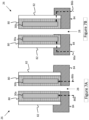
- the nozzle 26 comprises at least one pair of opposing electrodes located in a side-wall of bore of the nozzle. To provide a gliding arc plasma jet, the at least one pair of opposing electrodes are partially encapsulated within the side-wall and are partially exposed in the bore of the nozzle 26 (see also, for example, Figures 6A and 6B ). If a different type of plasma discharge or jet is to be provided, then a different encapsulation may be provided in the nozzle. For example, a dielectric plasma discharge may be provided by fully insulating the encapsulation of the nozzle electrodes in the side walls of the nozzle in some embodiments (see Figures 7A and 7B ).
- the electrodes located in the side-walls of the nozzle bore are encapsulated by the nozzle body so that they are not in direct contact with the working gas as it passed through the nozzle bore.
- the leads or the electrodes are exposed through the external side-walls of the nozzle or base of the nozzle in a suitable manner to form electrical contacts with the leads 86a, 86b (see Figures 6A,6B , 7A, 7B ) from the high-voltage generator.
- the portable hand tool also includes a gas source, which may be an air inlet or a gas canister.
- the gas source is at least partially integrated in or attached to the casing and connected to a gas delivery channel within the casing so as provide a working gas via the gas delivery channel into an inner bore of the nozzle under the control of a trigger or similar actuator in the handle of the tool casing.
- a trigger switch may be used in some embodiments of the tool to both trigger a gas flow via the nozzle and/or to ignite the gas to form a plasma as it flows out of the nozzle 26.
- a switch to actuate a power supply for the high voltage generator, a voltage is applied within the nozzle bore between the at least one pair of opposing electrodes. This voltage is sufficiently high to cause the resulting electric field which is generated across at least a part of the inner bore of the nozzle 26 to ignite the working gas delivered via the gas delivery channel into the inner bore.
- the portable plasma jet hand tool may have a "gun" type configuration where a working gas source, whether an air inlet in the casing or a gas canister for a working gas another than air which is incorporated into the tool body, for example, into the handle of the hand tool, allows the handle of the plasma jet hand tool to be held by a user with one hand and the tool operated by pressing a trigger or actuator to both draw gas and ignite the plasma.
- a benefit of the portable plasma jet hand tool is that it allows safe one-handed operation by a user, even when being used to generate a gliding arc type of plasma.
- embodiments of the portable plasma jet hand tool device may be compact, lightweight, and portable. Whilst another hand may be used to steady or to provide further support when the device is in use, this is not a requirement. Moreover, prolonged operation of the device, even when a gliding arc discharge plasma jet is being generated, is possible with less fatigue and more flexibility as there is no need to connect the portable plasma jet hand tool device via a hosepipe to an external gas supply.
- the nozzle is a removable nozzle which is interchangeable or replaceable with another nozzle configured to provide a different type of plasma jet from the same type of working gas or a different type of working gas.
- the nozzle is interchangeable or replaceable with another nozzle having one or more or all of: a different inner bore configuration to the inner bore configuration of the nozzle being replaced, a different number of pairs of opposing electrodes to the at least one pair of opposition electrodes of the nozzle being replaced, and a different electrode configuration to the configuration of at least one electrode of the at least one pair of opposing electrodes of the nozzle being replaced.
- the other nozzle encapsulates at least one pair of opposing electrodes located within a side wall of a bore of the other nozzle, wherein the at least one pair of opposing electrodes of the other nozzle are insulated by their encapsulation, and the portable plasma jet hand tool is reconfigured to provide a dielectric barrier discharge type of plasma jet.
- nozzle electrodes 30 The configuration of nozzle electrodes 30 is not shown in Figure 1 , see, for example, Figures 2A to 2F , Figures 3A-3D , and Figures 4A-4F for various examples of electrode configurations in the nozzle 26.
- the gas used to form the plasma may be air in some embodiments, or another type of gas or a gas mixture in other embodiments.
- the gas source 20 may be an air intake if the gas used is unpressurised air as shown in Figure 1 or a connected gas canister if the gas is pressurized air or another gas or gas mixture, not shown in Figure 1 . If the gas suppled is air, then in some embodiments, the gas source 20 may comprise a blower in the form of an impeller or fan, which may be powered or controlled via a motor 21.
- the blower is configured to draw air via inlets in the casing 12 in from the environment around the portable plasma jet hand tool 10 and blows the air along the gas delivery channel 22 into the nozzle bore 28 of the attached nozzle 26 and past electrodes 30.
- the plasma tool 10 configured to use ambient air as a gas to supply the plasma jet, there is no need to use an external (or internal) air compressor or other compressed gas source to generate sufficient airflow past the electrodes.
- the gas source 20 may be a pressurized gas source.
- a separate blower to drive the pressurized gas out along the gas delivery channel 22 may be not always be required.
- the gas source 20 may comprise a canister gas source 20 in some embodiments, and one aspect of the disclosed technology accordingly relates to a gas canister configured be connected to a hand held portable plasma jet hand tool 10 according to any of the disclosed embodiments.
- the high voltage generator 18 is located in the body 84 of the portable plasma jet hand tool 10 and is configured with leads 86a,86b (see Figures 6A, 6B and 7A and 7B ) which are connected to connectors of the electrodes 30 (shown as a pair of opposite electrodes 30a, 30b in Figures 6A, 6B , 7A and 7B and the figures 2A-F , 3A-D , 4A-F )of nozzle 26 when the nozzle 26 is attached to the portable plasma jet hand tool.
- the high voltage generator 18 is located close to the nozzle 26 so that the length of the high voltage leads 86a 86b connecting the voltage generator 18 to the electrodes 30 in the nozzle 26 is as short as possible. By locating the high voltage generator in the gas delivery channel 22 it also allows the gas (or air) stream flowing in the gas delivery channel 22 to chill the electronic components of the high voltage generator 18. This may prolong their operational lifetimes by preventing overheating from use of the tool 10.
- the power source 16 could be a mains power source in some embodiments, in the embodiment shown in Figure 1 , the power supply 16 is provided by a battery.
- Battery technology is continuously improving but there are currently batteries such as 18 volt rechargeable battery which have suitable Amp levels, for example, 10Ah, which can support a useful operational time of the portable plasma jet hand tool.
- Some embodiments of the portable plasma jet hand tool use one or more high-power batteries such as, for example, those of the CAS Cordless Alliance System TM .
- Typical characteristics of high-power batteries include the ability to provide e.g. 10Ah at 18V or up to 3kW. This allows the portable plasma jet hand tool to be reduced in size to a form factor typically associated with those of a handheld electric tool and operated for substantial periods of time.
- the use of a battery as a power source also allows the portable plasma jet hand tool to be operated as a portable hand-held tool and used in environment where no mains power is available.
- the portable plasma jet hand tool 10 battery may be charged within the tool or externally.
- the portable plasma jet hand tool 10 has a nozzle 26 is detachable and which may be interchanged with nozzles 26 having different internal and/or external configurations, such as the nozzle described in more detail later below in relation to Figures 2A-2F , 3A-3D , and 4A-4F .
- the gas supply channel 22 may be cylindrical, but may have other configurations, so long as a minimal obstruction to the airflow is ensured.
- the cross section may particularly be different in the nozzle region (for example, see the example nozzle bore 28 having a rectangular cross section as shown schematically in Figures 4A-4F ).
- the centers of the cross sections of the gas delivery channel and nozzle bore are aligned at the point where nozzle and portable plasma jet hand tool body connect to each other.
- the gas delivery channel inner dimensions and/or nozzle bore inner dimensions are uniform in diameter along the longitudinal direction/axis of the bores.
- the inner dimensions of the gas delivery channel and/or the nozzle more are not uniform along the longitudinal direction/axis of the bores.
- the nozzle bore 28 may taper or otherwise change its cross-sectional area in the nozzle region in some embodiments. Nonetheless, the cross section of the nozzle bore 28 is dimensionally configured in such a way that the electrode tips protruding into the gas delivery channel do not impede the airflow to any significant degree.
- a constriction within the gas delivery channel should not be formed by the electrodes emerging from the inner nozzle bore wall whilst still allowing the electrodes to be sufficiently close enough to ignite an electric discharge in the air or whatever gas or gas mixture is flowing past due to the high-voltage drop in the region of the nozzle bore between the electrodes.
- suitable airflow velocities along the gas delivery channel 22 from the air inlet to the nozzle tip outlet may range from 5 m/s to 50 m/s, but is preferably between 10 m/s and 20 m/s.
- the supply 20 is configured to generate a sufficient high airflow speed top results in an overpressure upstream from the nozzle.
- the nozzle 26 comprises at least an inner bore 28 to which case is delivered by the gas delivery channel 22 when the nozzle is attached to the portable plasma jet hand tool 10, at least one pair of electrodes 30 configured around the inner bore 28, at least one pair of electrode connectors, wherein the electrode connectors are configured such that when the nozzle is attached to the casing body 12 of the portable plasma jet hand tool 10 so that the inner bore 28 of the nozzle 12 is aligned with the gas delivery channel 22, the connectors are in contact with leads of the high voltage generator 18 of the portable plasma jet hand tool 10.
- FIGS 2A-2F , 3A-3D , and 4A-4F these illustrate example embodiments of such a nozzle 26 which may be removable from the portable plasma jet hand tool 10 and replaced with a nozzle of the same or a different nozzle configuration.
- a nozzle according to the example embodiment illustrated in Figure 2A-2F may be replaced with a nozzle according to the embodiments illustrated in Figures 3A to 3D or 4A to 4F .
- All of the example embodiments of nozzle 26 illustrated in Figures 2A-2F , 3A to 3D , and 4A to 4F are configured such that the inner nozzle bore 28 does not overly constrict the airflow which ensures a sufficiently high airflow velocity and volume flow through the nozzle 26 to form the plasma jet.
- the nozzle 26 shown in any of these figures is attached to the plasma tool, an electrical connection is formed between the high voltage generator 18 of the portable plasma jet hand tool 10 and the electrodes 30 located in the nozzle body, namely, electrodes shown as 30a, 30b, in Figures 2A-2F and 4A-4F , and the electrodes shown as 30a-30d in Figures 3A-3D .
- the high voltage generator applies a sufficiently high-voltage so that the electromagnetic field which forms across the nozzle bore 28 causes an electrical discharge in the gas flowing between each pair of electrodes such that the resulting plasma then emerges from the nozzle 26 in the form of a plasma jet.
- connection leads to the electrodes are located far enough apart to avoid arcing between the leads, in other words, further apart then the electrodes might be in any given configuration. This minimizes capacitive losses between the leads for non-RF operation frequencies.
- the high voltage, HV, leads are positioned on opposite sides of the gas channel, whereas all non-HV connections are located at approx. equal distance to opposing HV leads.
- one HV electrode is located on the one side of the channel or bore in the nozzle side wall and one is located on the opposite side of the channel or bore via which the working gas passes before exiting the nozzle as a plasma and all other contacts can be located at the top or at the bottom of the electrodes located in the nozzle. In this way, different nozzle heads with different electrode configurations can be used with the same plasma hand tool body for gliding arc and related technologies as well as, in some embodiments, DBD or Corona plasmas.
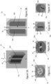
- Figures 2A to 2F show different views of a first example embodiment of a nozzle 26 for use in a portable plasma jet hand tool 10 according to some embodiments of the disclosed technology.
- Figure 2A shows a 3D cut-away view in which nozzle 26 has been cut in half along the longitudinal axis 32 of the inner bore 28 of nozzle 26. The cut-away view shows the longitudinal axis 32 from A-A' of the nozzle bore 28 as well as the two electrodes 30a, 30b disposed on opposite sides of the nozzle bore 28.
- Figure 2B shows the same cut-away view of Figure 2B in two-dimensions as a planar cut through the nozzle 26 and also shows the nozzle bore 28 disposed between the two electrodes 30a, 30b.
- Figure 2C shows the view of the nozzle looking down from the top end A', where the nozzle tapers inwards at its tip to form a dielectric body 36 and also shows how electrodes 30a, 30b extend through surface 38 of the inner bore 28 of the nozzle 26 and protrude into the airflow from within the nozzle jacket 34.
- Figure 2D shows the view from the other end A of nozzle 26 in which the electrodes 30a, and 30b are shown in relation to a sensor cavity 40.
- Sensor cavity 40 is also shown in Figure 2E , which presents a different 3D side cut through the nozzle 26 from that shown in Figure 2B . As shown in Figure 2E , the sensor cavity 40 extends longitudinally off the central longitudinal axis 32 of the nozzle bore 28. Air (or whatever gas or gas mixture is being used) flows along the bore in the direction A to A' through the nozzle 26.
- Figure 2F shows a 3D view of the nozzle shown in Figures 2A to 2E from end A.
- the inner surface of the nozzle 26, i.e. the surface of the nozzle bore 28, is provided by a non-conductive and heat-resistant casing.
- the electrodes 30 of the nozzle are encapsulated as shown in Figures 2A-2F to avoid any need for a ground connection. This allows, the portable plasma jet hand tool to be safely used as a cordless hand-tool.
- the outer surface of the casing 12, which forms the tool handle, maintains a neutral potential as a result of the encapsulation.
- Figures 2E and 2F illustrate schematically how a sensor cavity or chamber 40 is provided in some embodiments within nozzle 26 to house one or more sensors so that they are isolated from the plasma within the nozzle 26.
- a sensor chamber 40 which is isolated from the plasma by being encased within the nozzle side-wall as shown in, for example, the nozzle as illustrated in Figures 2A to 2F the sensors will be electrically isolated and so protected from the high voltage electrodes used to generate the electrical fields which ignite the plasma as well as from any sparks which may also be generated.
- the nozzle 26 and/or the plasma hand tool 10 instead or in addition are provided with other sensors, some or all of which may not completely isolated or which are house elsewhere along the gas supply channel 22.
- sensors which may be located within a cavity or chamber in the nozzle 26 or elsewhere in some embodiments include one or more of the following types of sensors: a temperature sensor; a voltage sensor; and gas flow sensor.
- the gas flow sensor may be located within the gas supply channel 22 (also referred to herein as gas delivery channel 22). This frees up some space within the nozzle 26 for housing other sensors.
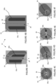
- Figures 3A to 3D show a second example of a nozzle 26 for use in a portable plasma jet hand tool 10 according to some embodiments of the disclosed technology where two pairs of electrodes are arranged around the inner bore 28 of nozzle 26.
- the nozzle 26 is configured to have four electrodes 30a-30d arranged around the longitudinal axis 32 of the nozzle which are completely encased within the nozzle 26 and are equally spaced radially around the central longitudinal axis A-A'. Gas flows in from end A and is ignited as it passes through the region between the four electrodes 30a, 30b,30c, and 30d, before emerging as a plasma jet at end A'.
- Figure 3A shows a side view of the nozzle 26 showing a sensor chamber 42, which is open at the nozzle base end A, but otherwise encapsulated within the nozzle sidewalls.
- the nozzle 26 shown in Figures 3A to 3D externally has a tapered nozzle tip 34 with a nozzle bore 28 having a uniform diameter which is aligned with gas delivery channel 22 in use such that there is no obstruction to the gas delivered via the gas delivery channel 22 which flows from end A to end A' of the nozzle as shown.
- Figure 3A just two of the four electrodes (the electrodes labelled 30a and 30b) are shown.
- Figure 3B shows another side view of the nozzle 26 shown in Figure 3A in which a tip of a third electrode 30c is shown protruding into the nozzle bore 28 between electrodes 30a and 30b.
- Figure 3C is a plan view facing down from the nozzle tip, in other words looking down along nozzle bore 28 along axis 32 from the nozzle end A'.
- Figure 3C shows how the nozzle tip tapers inwards towards the open gas delivery channel 22 and also shows four electrodes 30A, 30B, 30C and 30D protruding slightly through the nozzle's inner surface into the nozzle bore 28...
- Figure 3D shows a view of nozzle 26 from the end A, which is configured to engage with the portable plasma jet hand tool casing 12. As shown in Figure 3D , the four electrodes 30A-30D are shown arranged at right angles around and protruding into nozzle bore 28. Figure 3D also shows schematically the location of the sensor chamber 42 which in a similar manner to that shown in figures 2A to 2F extends longitudinally offset from the inner bore 28 of the nozzle 26.
- the electrodes 30a-30d may be flush with or encapsulated within the bore sidewall(s).
- the encapsulation is conductive in some embodiments, thus improving the characteristics of a gliding arc plasma discharge or similar type of plasma discharge from the nozzle of the portable plasma jet hand tool.
- the nozzle encapsulation of the electrodes is insulating, which allows the tool to be used as a portable plasma jet hand tool for a dielectric barrier discharge (DBD) plasma.
- DBD dielectric barrier discharge
- changing a nozzle providing insulating encapsulation of a first configuration of a plurality of electrodes within the nozzle bore sidewalls to another nozzle providing conductive encapsulation of a second configuration of a plurality of electrodes within the bore sidewalls changes the type of plasma jet discharged from the nozzle of the plasma jet hand tool.
- the type of plasma jet discharged from the tool can be changed by selecting a different type of nozzle, allowing the same plasma jet hand tool body to be used for both an arc-type plasma discharge, for example, a gliding arc plasma discharge, and dielectric barrier discharge plasmas, depending on which type of nozzle has been attached to the tool housing head.
- Figures 4A to 4F show yet another example embodiment of a nozzle for use in a portable plasma jet hand tool 10 according to some embodiments of the disclosed technology, which differs from the example nozzle of Figure 2A to 2F in that the nozzle bore 28 is non-cylindrical.
- the nozzle bore 28 is formed by a rectangular cavity within the cylindrical nozzle body, and when attached to the portable plasma jet hand tool 10, the gas delivery channel 22 of the portable plasma jet hand tool 10 is aligned with the nozzle bore 28.
- two electrodes 30a, 30b are shown located in the nozzle sidewall and disposed on opposite sides so that when the high voltage generator 18 of the plasma hand tool 10 is connected to the electrodes an strong enough electromagnetic field is formed in the nozzle bore to cause the gas flowing through the nozzle bore to ignite and form a plasma which then discharges from the nozzle tip at end A'.
- Figure 4A shows a 3D side view cut out of nozzle 26
- Figure 4B shows a 2D view of the nozzle shown in Figure 4A
- Figure 4C shows a 2D view of the nozzle from its base end A (the end which attaches to the casing 12 of the plasma hand tool)
- Figure 4D shows a three-dimensional view of the nozzle depicted in Figure 4C
- Figure 4E shows the view of the nozzle at the opposite end to open tip end A', from which the plasma jet emerges, which is shown in Figure 4F .
- the electrodes 30a and 30b do not protrude significantly into the rectangular nozzle bore 28 so as to ensure the gas or flow is not obstructed.
- the nozzle bore 28 is dimensioned to cause the gas or air flowing past the electrodes 30 to ignite an electrical discharge in the gas or air as it flows through the nozzle bore 28.
- the gas or air may also include a gas mixture (which may also be a gas and air mixture) in some embodiments.
- the portable plasma jet hand tool 10 comprises a nozzle 26 which is replaceable, in other words, the nozzle 26 is removable from the casing 12 of the portable plasma jet hand tool 10 and different types of nozzle may be configured to be interchangeable on the same body of the portable plasma jet hand tool 10.
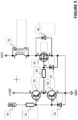
- Any suitable high voltage generator circuit may be used to form the high voltage generator 18 which applies the high voltages to electrodes 30 in the nozzle 26 when the nozzle 26 is attached to the portable plasma jet hand tool body.
- FIG. 5 shows an example circuit schematic in which the required high voltage potentials are produced using a Flyback-type circuit.
- a power transistor 64 such as a metal-oxide semiconductor field-effect transistor or an insulated gate bipolar transistor, with a freewheeling diode 68 for reverse voltage protection.
- the high pulse currents upon charging and discharging the transistor gate with a pulse-width modulated signal 50 requires a suitable driver component e.g. as an integrated circuit (IC, not shown) or implemented by a pair of bipolar transistors 56,58 in push-pull configuration.
- IC integrated circuit
- Typical safety features include a resistor 52 limiting signal currents on the input side of the driver component 56,58 another limit resistor 60 on the output side between driver components 56,58 and main transistor 64, as well as a Zener diode 54 on the input side of the driver components 56,58 and a Zener diode 62 on the gate contact of the main transistor 64.
- a nozzle 26 such as the examples of Figure which is configured to be attached permanently or removabley to a casing 12 of a hand-held portable plasma jet hand tool, for example, such as the portable plasma jet hand tool 10 shown in Figure 1 .
- the nozzle comprises a portion of the gas delivery channel 22, a connected nozzle bore and at least two electrodes 30a, 30b configured to form a high electric field across the nozzle bore, and power connector(s).
- the part of gas delivery channel 22 formed in nozzle 26 is aligned with the portion of the gas delivery channel 22 formed in the body of the portable plasma jet hand tool and the at least two electrodes are configured to receive power from the portable plasma jet hand tool via the power connection.
- Any suitable power connection mechanism may be used.
- some embodiments of a removable nozzle may encompass parts of the electronic sensor or control circuitry, or parts of the electronics generating the high voltage.
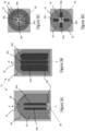
- Figures 6A and 6B show schematically examples of how the electrodes 30a 30b of the nozzle 26 for a gliding arc set up are embedded within insulating encapsulation 80 forming the nozzle side-wall or are embedded within an insulating liner of the bore 28 of nozzle 26.
- the insulating encapsulation 80 prevents the high-voltage electricity from going anywhere other than into the working gas to generate the plasma.
- an outer conductive encapsulation 82 surrounds the insulating encapsulation to prevent HV arcing, in other words, to prevent electricity leaking outside the nozzle.
- leads 86a embedded in the insulating encapsulation emerge and pass via the body 84 of the plasma hand tool to the HV generator 18 to provide electricity to the electrodes 30a, 30b.
- additional leads 86c,d may be provided to accommodate possibly different electrode configurations and/or numbers of electrodes, e.g. 30c, 30d.
- the conductive surface 82 encapsulates the entire nozzle in some embodiments to provide a safety feature which reduces or prevents any HV arcing or leaking to the outside of the hand-tool housing.
- Figures 7A and 7B are similar to Figures 6A and 6B but show schematically examples of how the electrodes 30a 30b of the nozzle 26 for a DBD plasma jet are fully embedded within insulating encapsulation 80 of the nozzle wall or fully enclosed within an insulating liner of the bore 28 within nozzle 26 in some embodiments of the disclosed technology.
- a separate layer or similar form of electrode insulation may be provided, for example, a glass or ceramic tube over the electrode may be used to provide insulating encapsulation over the electrodes in some embodiments (not shown in Figures 7A or 7B ).
- the insulating encapsulation which surrounds the electrodes previous the high-voltage electricity from going anywhere other than into the working gas to generate the plasma.
- an outer conductive encapsulation surrounds the insulating encapsulation to prevent electricity leaking outside the nozzle 26 and/or HV arcing.
- leads 86a, 86b are configured to engage via the base of the nozzle with the electrodes whereas in Figures 6B and 7B the leads 86a, 86b engage via the bottom of the side-walls with the electrodes. It will be apparent to any one of ordinary skill in the art that a variety of different configurations, including the leads 86a, 86b in the body 84 of the hand tool connecting with the electrodes 30a, 30b via leads within the nozzle 26 are possible.
- Different types of nozzle may require different operating parameters (frequency, duty cycle, voltages%) in some embodiments. If so, then in some embodiment the different operating parameters may be programmed through electronic components within the nozzle. This allows a user to simply swap nozzles for different applications and the nozzle and plasma jet will be adapted for any new operational requirements without the need to change any settings or otherwise manipulate the device
- Changing the nozzles may change the plasma jet configuration so that a different shaped jet is provided. If the electrodes or sensors in the nozzle fail, for example, due to wear, instead of changing the entire portable plasma jet hand tool 10, just the nozzle 26 needs to be replaced. For example, in some embodiments, where nozzle (12) encapsulates at least one sensor when attached to the portable plasma jet hand tool body, it may be desirable for some applications to use a more sensitive temperature sensor or more sensitive airflow sensor. Nozzles may also be changed for different applications.
Landscapes
- Physics & Mathematics (AREA)
- Engineering & Computer Science (AREA)
- Plasma & Fusion (AREA)
- Spectroscopy & Molecular Physics (AREA)
- Plasma Technology (AREA)
Applications Claiming Priority (1)
| Application Number | Priority Date | Filing Date | Title |
|---|---|---|---|
| LU501366A LU501366B1 (en) | 2022-01-31 | 2022-01-31 | Plasma jet hand tool |
Publications (2)
| Publication Number | Publication Date |
|---|---|
| EP4221467A2 true EP4221467A2 (de) | 2023-08-02 |
| EP4221467A3 EP4221467A3 (de) | 2023-10-25 |
Family
ID=81307112
Family Applications (1)
| Application Number | Title | Priority Date | Filing Date |
|---|---|---|---|
| EP23154066.7A Pending EP4221467A3 (de) | 2022-01-31 | 2023-01-30 | Tragbares plasmastrahlhandwerkzeug |
Country Status (2)
| Country | Link |
|---|---|
| EP (1) | EP4221467A3 (de) |
| LU (1) | LU501366B1 (de) |
Cited By (1)
| Publication number | Priority date | Publication date | Assignee | Title |
|---|---|---|---|---|
| EP4486071A1 (de) * | 2023-06-28 | 2025-01-01 | Leibniz-Institut für Plasmaforschung und Technologie e.V. | Handhaltbares system zur behandlung von oberflächen mittels plasmas und verfahren zur behandlung von oberflächen mittels plasmas unter verwendung des handhaltbaren systems |
Family Cites Families (8)
| Publication number | Priority date | Publication date | Assignee | Title |
|---|---|---|---|---|
| BRPI0820864A2 (pt) * | 2007-12-10 | 2018-05-22 | Construction Research & Technology Gmbh | método e dispositivo para tratamento de superfícies |
| DE102013100617B4 (de) * | 2013-01-22 | 2016-08-25 | Epcos Ag | Vorrichtung zur Erzeugung eines Plasmas und Handgerät mit der Vorrichtung |
| DE102013109887A1 (de) * | 2013-09-10 | 2015-03-12 | Reinhausen Plasma Gmbh | Handgerät und Verfahren zur Plasmabehandlung |
| GB201401137D0 (en) * | 2014-01-23 | 2014-03-12 | Linde Aktiengesellshcaft | A nozzle for a plasma generation device |
| JP2016081842A (ja) * | 2014-10-21 | 2016-05-16 | 国立大学法人豊橋技術科学大学 | プラズマ処理装置 |
| EP3346808A1 (de) * | 2017-01-06 | 2018-07-11 | INP Greifswald Leibniz-institut Fuer Plasmaforschung Und Technologie E. V. | Planare vorrichtung und verfahren zur erzeugung eines plasmas oder reaktiver spezies |
| CN107580403A (zh) * | 2017-09-25 | 2018-01-12 | 深圳市中科摩方科技有限公司 | 一种手持式低温等离子体射流装置 |
| CN111107707A (zh) * | 2019-12-31 | 2020-05-05 | 河海大学常州校区 | 一种蓄电池供电的电晕灭菌装置 |
-
2022
- 2022-01-31 LU LU501366A patent/LU501366B1/en active IP Right Grant
-
2023
- 2023-01-30 EP EP23154066.7A patent/EP4221467A3/de active Pending
Cited By (1)
| Publication number | Priority date | Publication date | Assignee | Title |
|---|---|---|---|---|
| EP4486071A1 (de) * | 2023-06-28 | 2025-01-01 | Leibniz-Institut für Plasmaforschung und Technologie e.V. | Handhaltbares system zur behandlung von oberflächen mittels plasmas und verfahren zur behandlung von oberflächen mittels plasmas unter verwendung des handhaltbaren systems |
Also Published As
| Publication number | Publication date |
|---|---|
| LU501366B1 (en) | 2023-07-31 |
| EP4221467A3 (de) | 2023-10-25 |
Similar Documents
| Publication | Publication Date | Title |
|---|---|---|
| US20250048527A1 (en) | Device for producing a non-thermal atmospheric pressure plasma and active space comprising such a device | |
| KR101387878B1 (ko) | 휴대용 자주 물질 처리 시스템 | |
| US5039837A (en) | Plasma torch head, body, handle and control circuitry | |
| US4701590A (en) | Spring loaded electrode exposure interlock device | |
| US6522150B2 (en) | Corona discharge apparatus | |
| CN1500024A (zh) | 接触起动的等离子体焊炬 | |
| EP4221467A2 (de) | Tragbares plasmastrahlhandwerkzeug | |
| JPS62155955A (ja) | 静電噴射ピストル | |
| US20150132711A1 (en) | Plasma treatment device | |
| EP0899016A3 (de) | Sprühpistole | |
| CN102742364A (zh) | 用于生成气态核素的设备 | |
| US11637449B2 (en) | Wireless charging air compressor | |
| TW201400191A (zh) | 靜電噴塗工具的電源供應器 | |
| CN110036696B (zh) | 等离子体电动工具 | |
| WO2023015207A1 (en) | Plasma-generating nozzle and plasma device including same | |
| JP2009099472A (ja) | 送風式イオン生成装置 | |
| CA2407815C (en) | Coating-powder spray gun | |
| ES2222423T3 (es) | Procedimiento y dispositivo para proteger un entorno explosivo de un componente electronico a traves de intercambio de aire. | |
| JP4664090B2 (ja) | エアーノズル型イオン生成装置 | |
| JP2001297898A (ja) | プラズマ表面処理装置 | |
| EP3467975A1 (de) | Verbesserungen an oder in ionisierten gasströmen | |
| JP3196758U (ja) | 携帯型塗装装置 | |
| CN120935917A (zh) | 一种低温等离子体发生装置 | |
| RU215068U1 (ru) | Портативный мобильный ультразвуковой распылитель жидкости | |
| KR20200092081A (ko) | 대기압 플라즈마 분사장치 |
Legal Events
| Date | Code | Title | Description |
|---|---|---|---|
| PUAI | Public reference made under article 153(3) epc to a published international application that has entered the european phase |
Free format text: ORIGINAL CODE: 0009012 |
|
| STAA | Information on the status of an ep patent application or granted ep patent |
Free format text: STATUS: THE APPLICATION HAS BEEN PUBLISHED |
|
| AK | Designated contracting states |
Kind code of ref document: A2 Designated state(s): AL AT BE BG CH CY CZ DE DK EE ES FI FR GB GR HR HU IE IS IT LI LT LU LV MC ME MK MT NL NO PL PT RO RS SE SI SK SM TR |
|
| PUAL | Search report despatched |
Free format text: ORIGINAL CODE: 0009013 |
|
| AK | Designated contracting states |
Kind code of ref document: A3 Designated state(s): AL AT BE BG CH CY CZ DE DK EE ES FI FR GB GR HR HU IE IS IT LI LT LU LV MC ME MK MT NL NO PL PT RO RS SE SI SK SM TR |
|
| RIC1 | Information provided on ipc code assigned before grant |
Ipc: H05H 1/24 20060101ALI20230919BHEP Ipc: H05H 1/48 20060101AFI20230919BHEP |
|
| STAA | Information on the status of an ep patent application or granted ep patent |
Free format text: STATUS: REQUEST FOR EXAMINATION WAS MADE |
|
| 17P | Request for examination filed |
Effective date: 20240422 |
|
| RBV | Designated contracting states (corrected) |
Designated state(s): AL AT BE BG CH CY CZ DE DK EE ES FI FR GB GR HR HU IE IS IT LI LT LU LV MC ME MK MT NL NO PL PT RO RS SE SI SK SM TR |