EP4223096A2 - Systèmes, procédés et appareil de détection de tranchée agricole - Google Patents
Systèmes, procédés et appareil de détection de tranchée agricole Download PDFInfo
- Publication number
- EP4223096A2 EP4223096A2 EP23166570.4A EP23166570A EP4223096A2 EP 4223096 A2 EP4223096 A2 EP 4223096A2 EP 23166570 A EP23166570 A EP 23166570A EP 4223096 A2 EP4223096 A2 EP 4223096A2
- Authority
- EP
- European Patent Office
- Prior art keywords
- trench
- depth
- light source
- seed
- light
- Prior art date
- Legal status (The legal status is an assumption and is not a legal conclusion. Google has not performed a legal analysis and makes no representation as to the accuracy of the status listed.)
- Pending
Links
Images







Classifications
-
- A—HUMAN NECESSITIES
- A01—AGRICULTURE; FORESTRY; ANIMAL HUSBANDRY; HUNTING; TRAPPING; FISHING
- A01B—SOIL WORKING IN AGRICULTURE OR FORESTRY; PARTS, DETAILS, OR ACCESSORIES OF AGRICULTURAL MACHINES OR IMPLEMENTS, IN GENERAL
- A01B79/00—Methods for working soil
- A01B79/005—Precision agriculture
-
- A—HUMAN NECESSITIES
- A01—AGRICULTURE; FORESTRY; ANIMAL HUSBANDRY; HUNTING; TRAPPING; FISHING
- A01C—PLANTING; SOWING; FERTILISING
- A01C5/00—Making or covering furrows or holes for sowing, planting or manuring
- A01C5/06—Machines for making or covering drills or furrows for sowing or planting
- A01C5/066—Devices for covering drills or furrows
- A01C5/068—Furrow packing devices, e.g. press wheels
-
- A—HUMAN NECESSITIES
- A01—AGRICULTURE; FORESTRY; ANIMAL HUSBANDRY; HUNTING; TRAPPING; FISHING
- A01B—SOIL WORKING IN AGRICULTURE OR FORESTRY; PARTS, DETAILS, OR ACCESSORIES OF AGRICULTURAL MACHINES OR IMPLEMENTS, IN GENERAL
- A01B27/00—Clod-crushers
- A01B27/005—Clod-crushers comprising roller-type tools moving on the ground
-
- A—HUMAN NECESSITIES
- A01—AGRICULTURE; FORESTRY; ANIMAL HUSBANDRY; HUNTING; TRAPPING; FISHING
- A01B—SOIL WORKING IN AGRICULTURE OR FORESTRY; PARTS, DETAILS, OR ACCESSORIES OF AGRICULTURAL MACHINES OR IMPLEMENTS, IN GENERAL
- A01B63/00—Lifting or adjusting devices or arrangements for agricultural machines or implements
- A01B63/002—Devices for adjusting or regulating the position of tools or wheels
- A01B63/008—Vertical adjustment of tools
-
- A—HUMAN NECESSITIES
- A01—AGRICULTURE; FORESTRY; ANIMAL HUSBANDRY; HUNTING; TRAPPING; FISHING
- A01B—SOIL WORKING IN AGRICULTURE OR FORESTRY; PARTS, DETAILS, OR ACCESSORIES OF AGRICULTURAL MACHINES OR IMPLEMENTS, IN GENERAL
- A01B79/00—Methods for working soil
- A01B79/02—Methods for working soil combined with other agricultural processing, e.g. fertilising, planting
-
- A—HUMAN NECESSITIES
- A01—AGRICULTURE; FORESTRY; ANIMAL HUSBANDRY; HUNTING; TRAPPING; FISHING
- A01C—PLANTING; SOWING; FERTILISING
- A01C23/00—Distributing devices specially adapted for liquid manure or other fertilising liquid, including ammonia, e.g. transport tanks or sprinkling wagons
- A01C23/02—Special arrangements for delivering the liquid directly into the soil
- A01C23/023—Special arrangements for delivering the liquid directly into the soil for liquid or gas fertilisers
- A01C23/025—Continuous injection tools
-
- A—HUMAN NECESSITIES
- A01—AGRICULTURE; FORESTRY; ANIMAL HUSBANDRY; HUNTING; TRAPPING; FISHING
- A01C—PLANTING; SOWING; FERTILISING
- A01C5/00—Making or covering furrows or holes for sowing, planting or manuring
- A01C5/06—Machines for making or covering drills or furrows for sowing or planting
- A01C5/062—Devices for making drills or furrows
- A01C5/064—Devices for making drills or furrows with rotating tools
-
- A—HUMAN NECESSITIES
- A01—AGRICULTURE; FORESTRY; ANIMAL HUSBANDRY; HUNTING; TRAPPING; FISHING
- A01C—PLANTING; SOWING; FERTILISING
- A01C7/00—Sowing
- A01C7/006—Minimum till seeding
-
- A—HUMAN NECESSITIES
- A01—AGRICULTURE; FORESTRY; ANIMAL HUSBANDRY; HUNTING; TRAPPING; FISHING
- A01C—PLANTING; SOWING; FERTILISING
- A01C7/00—Sowing
- A01C7/06—Seeders combined with fertilising apparatus
-
- A—HUMAN NECESSITIES
- A01—AGRICULTURE; FORESTRY; ANIMAL HUSBANDRY; HUNTING; TRAPPING; FISHING
- A01C—PLANTING; SOWING; FERTILISING
- A01C7/00—Sowing
- A01C7/08—Broadcast seeders; Seeders depositing seeds in rows
- A01C7/10—Devices for adjusting the seed-box ; Regulation of machines for depositing quantities at intervals
- A01C7/102—Regulating or controlling the seed rate
- A01C7/105—Seed sensors
-
- A—HUMAN NECESSITIES
- A01—AGRICULTURE; FORESTRY; ANIMAL HUSBANDRY; HUNTING; TRAPPING; FISHING
- A01C—PLANTING; SOWING; FERTILISING
- A01C7/00—Sowing
- A01C7/20—Parts of seeders for conducting and depositing seed
- A01C7/201—Mounting of the seeding tools
- A01C7/203—Mounting of the seeding tools comprising depth regulation means
-
- G—PHYSICS
- G01—MEASURING; TESTING
- G01B—MEASURING LENGTH, THICKNESS OR SIMILAR LINEAR DIMENSIONS; MEASURING ANGLES; MEASURING AREAS; MEASURING IRREGULARITIES OF SURFACES OR CONTOURS
- G01B11/00—Measuring arrangements characterised by the use of optical techniques
- G01B11/22—Measuring arrangements characterised by the use of optical techniques for measuring depth
-
- A—HUMAN NECESSITIES
- A01—AGRICULTURE; FORESTRY; ANIMAL HUSBANDRY; HUNTING; TRAPPING; FISHING
- A01C—PLANTING; SOWING; FERTILISING
- A01C21/00—Methods of fertilising, sowing or planting
- A01C21/007—Determining fertilization requirements
-
- A—HUMAN NECESSITIES
- A01—AGRICULTURE; FORESTRY; ANIMAL HUSBANDRY; HUNTING; TRAPPING; FISHING
- A01C—PLANTING; SOWING; FERTILISING
- A01C7/00—Sowing
- A01C7/08—Broadcast seeders; Seeders depositing seeds in rows
-
- Y—GENERAL TAGGING OF NEW TECHNOLOGICAL DEVELOPMENTS; GENERAL TAGGING OF CROSS-SECTIONAL TECHNOLOGIES SPANNING OVER SEVERAL SECTIONS OF THE IPC; TECHNICAL SUBJECTS COVERED BY FORMER USPC CROSS-REFERENCE ART COLLECTIONS [XRACs] AND DIGESTS
- Y02—TECHNOLOGIES OR APPLICATIONS FOR MITIGATION OR ADAPTATION AGAINST CLIMATE CHANGE
- Y02P—CLIMATE CHANGE MITIGATION TECHNOLOGIES IN THE PRODUCTION OR PROCESSING OF GOODS
- Y02P60/00—Technologies relating to agriculture, livestock or agroalimentary industries
- Y02P60/20—Reduction of greenhouse gas [GHG] emissions in agriculture, e.g. CO2
Definitions
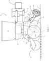
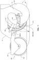
- FIG. 1 illustrates an agricultural implement, e.g., a planter, comprising a toolbar 8 to which multiple row units 10 are mounted in transversely spaced relation.
- Each row unit 10 may be mounted to the toolbar by a parallel arm arrangement 16 such that the row unit 10 is permitted to translate vertically with respect to the toolbar 8.
- An actuator 18 may be pivotally mounted to the toolbar 8 and the parallel arm arrangement 16 and configured to apply supplemental downpressure to the row unit 10.
- the row unit 10 includes a frame 14 supporting an opening disc assembly 60.
- the opening disc assembly 60 may include two angled opening discs 62 (62-1 and 62-2, respectively) rollingly mounted to a downwardly extending shank 15 of the frame 14 and disposed to open a v- shaped trench 3 in a soil surface 7 as the row unit advances in a forward direction of travel through a field.
- the row unit 10 may include a gauge wheel assembly 50 including two gauge wheels 52 pivotally mounted to either side of the frame 14 by two gauge wheel arms 54 (54-1 and 54-2, respectively) and disposed to roll along the surface of the soil.
- a closing assembly 40 may be pivotally coupled to the frame 14 and configured to move soil back into the trench 3 after the seeds have been deposited in the trench 3.
- seeds 5 are communicated from a hopper 12 to a seed meter 30 which may be configured to singulate the supplied seeds.
- the meter 30 may be a vacuum-type meter such as that disclosed in International Patent Publication No. WO2012/129442 .
- the seed meter 30 may dispense the singulated seeds into a seed tube 32 removably mounted to the frame 14.
- the seed tube 32 directs the seeds 5 dispensed by by the seed meter downwardly and rearwardly for depositing in the trench 3.
- a row cleaner assembly 200 such as disclosed in U.S. Patent No. 8,550,020 , may be mounted to the forward end of the row unit 10 via a bracket 202 attached to the shank 15. Row cleaner arms 204 are attached to the bracket 202 and extend downward to row cleaner wheels 206.
- An actuator 208 is disposed between the bracket 202 and a plate (not shown), which is mounted to forwardly extending row cleaner arms 204.
- the actuator 208 may be in signal communication with a monitor 50 (discussed later) for receiving signals to increase or decrease a downforce applied to the row cleaner assembly 200.
- the actuator 208 may be a pneumatic actuator as described in U.S. Patent No. 8,550,020 , or the actuator 208 may be hydraulic, electromechanical, or combinations thereof.
- the actuator 208 may be double acting or single acting.
- the depth adjustment assembly 90 includes a rocker 95 pivotally mounted to a depth adjustment body 94.
- the depth adjustment body 94 is pivotally mounted to the row unit frame 14 about the pivot 92.
- a handle 98 is slidably received within the depth adjustment body 94 such that the user can selectively engage and disengage the handle with one of a plurality of depth adjustment slots 97 ( FIG. 6 ) formed within the row unit frame 14.
- the upward travel of the gauge wheels 52 is limited by contact of the gauge wheel arms 54 with the rocker 95.
- the rocker 95 allows the left gauge wheel arm 54-1 to travel upward while lowering the right gauge wheel 52-2 by the same absolute displacement such that the row unit 10 rises by half the height of the obstruction.
- agricultural row unit 10 can optionally further include a trench closing assembly 250.
- the trench closing assembly 250 includes a closing wheel arm 252 which pivotally attaches to the row unit frame 14.
- a pair of offset closing wheels 254 are rotatably attached to the closing wheel arm 252 and are angularly disposed to "close" the seed trench 10 by pushing the walls of the open seed trench back together over the deposited seed 5.
- An actuator may be pivotally attached at one end to the closing wheel arm 252 and at its other end to the row unit frame 14 to vary the down pressure exerted by the closing wheels 254 depending on soil conditions.
- the closing wheel assembly 250 may be of the type disclosed in International Patent Publication No. WO2014/066650 .
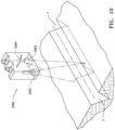
- a light plane triangulator 2000 such as a laser line triangulator, is disposed on shank 15 of agricultural row unit 10 to measure a depth of a trench created by row unit 10.
- the light plane triangulator 2000 includes a body 1001 in which a light source 2002, such as a laser light, and a receiver 2003 are disposed.
- the receiver 2003 is disposed at an angle to the light source 2002 to receive reflected light from a surface upon which light source 2002 illuminates.
- a sensor matrix 2004 is connected to the receiver 2003 to generate an output signal comprising an image or pattern based on the reflected light from which a data frame is generated providing characteristics of the trench.
- a light plane triangulator 2000 in the form of a laser line triangulator is the scanCONTROL 2D/3D laser scanner (laser profile sensor) from Micro-Epsilon of Raleigh, North Carolina, USA, as disclosed in published Brochure No. Y9766353-G021077GKE, incorporated herein by reference and attached as Appendix A.
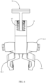
- a light source 2002 and receiver 2003 and sensor 2004 can be separately disposed on row unit 10 to allow for placement around other parts on the row unit 10 and still measure the depth of the seed trench 3.
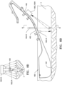
- the light source 2002, receiver 2003 and sensor 2004 may be disposed on a rearwardly extending appurtenance 400 supported from a bracket 410 mounted to the shank 15 or frame 14 of the row unit 10 and in longitudinal alignment with the trench 3.
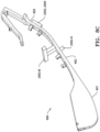
- the appurtenance 400 may be a seed firmer having a trailing end disposed in the trench 3.
- the appurtenance 400 may be an arm that extends rearwardly above the soil surface.
- the light source 2002-A may be disposed under the appurtenance or seed firmer 400, or the light source 2002-B may be disposed over seed firmer 400, or both light source 2002-A and light source 2002-B may be used in combination.
- seed firmer 400 has a ground engaging portion 401, an upper portion 402, and a mounting portion 403.
- Receiver 2003 and sensor 2004 may be disposed on mounting portion 403 and disposed to view the seed trench 3.
- Light source 2002-A and light source 2002-B may be disposed on the upper portion 402 to direct the light into the trench 3.
- Light source 2002-A can provide light under seed firmer 400, and light source 2002-B can provide light to either or both sides of seed firmer 400.
- light plane triangulator 2000 may be disposed as a whole unit or by its parts anywhere on row unit 10 that has a view of trench 38.
- Light plane triangulator 2000 is in data communication with depth control and a soil monitoring system 300 (discussed later). A depth measured by light plane triangulator 2000 can be displayed on monitor 50 and/or a depth of the trench can be adjusted either manually or automatically as described below.
- the wavelength of the light source can be modulated or alternated to generate different data frames.
- Each data frame containing the triangulated line pattern and intensity values of the reflected light along the triangulated line pattern for one wavelength.
- Data Frame A can use 640 nm (red)
- Data Frame B can use 940 nm (infrared).
- the relationship between the intensity values of the pattern of Data Frame A and the pattern of Data Frame B can provide information about the seed trench 3, such as relative moisture versus depth profile of the seed trench 3, identify topsoil falling onto seed, residue falling into seed trench 3, identify seed placement in the seed trench 3 including seed location paired with GPS coordinates, seed spacing, seed population, and/or seed orientation in seed trench 3.
- more than two data frames of varying wavelengths such as Data Frame A, Data Frame B, and Data Frame C, can be used.
- the data frame may be based on four generated images captured using the reflected light. For example, a first wavelength A of structured light is used to illuminate seed trench 3, generating Image A. Wavelength A is then turned off. A second wavelength B of structured light is used to illuminate seed trench 3, generating Image B. Wavelength B is then turned off. Image C is generated with no light illuminating seed trench 3. A white light may be used to illuminate seed trench 3, generating Image D. The white light is then turned off. The generation of Image A, Image B, Image C, and Image D can be done in any order. For the following calculations, when Image D is not used, the generation of Image D can be omitted.
- a Net Image A pattern is calculated or derived by subtracting Image C from Image A.
- a Net Image B pattern is calculated or derived by subtracting Image C from Image B.
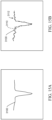
- An example of subtracting images is illustrated in FIG. 14A .
- the Net Image A or Net Image B patterns can then be scaled and filtered to produce a data frame providing characteristics of the trench, wherein the triangulated line pattern and intensity values along the triangulated pattern varies by soil characteristics, which is illustrated in FIG. 14B .
- SD represents seed depth.
- the depth RC is subtracted from depth SD to provide a depth of the row cleaner trenching.
- FIG. 14C illustrates a display screen 3000 showing the row cleaner trenching depth and seed depth.
- gauge wheels 52 can compress a portion of seed trench 3.
- Full trench depth is the depth from the top of seed trench 3 to the bottom of seed trench 3 as measured by depth SD.
- the depth of gauge wheels 52 to full trench depth can be determined as the difference between depth SD and depth RC.
- Net Image A or Net Image B pattern can also be used to measure a uniformity of the furrow.
- the filtered and scaled Net Image A or Net Image B are used for the calculation.
- Net Image A or Net Image B is compared to a trench profile curve.
- image to image comparisons can be used.
- root mean square (RMS) error is used to compare Net Image A or Net Image B to a nominal trench shape.
- FIG. 15A is intended to illustrate a trench profile 3100 having 99% uniformity.
- FIG. 15B is intended to illustrate a trench profile 3100 having 75% uniformity with a trench profile curve 3110.
- the trench profile 3100 can be displayed on monitor 50 graphically as illustrated in FIGs. 15A or 15B or numerically as a percent uniformity.
- Uniformity can be displayed based on the individual values calculated, or a running average over a selected time or distance can be used. In another embodiment, voids 3112 greater than a selected size can be counted to determine the amount of uniformity. In another method, standard deviation from trench profile curve 3110 can be calculated and then averaged between multiple images.
- FIG. 16 illustrates the process for calculation. Reflected intensity of wavelength A 3200 and reflected intensity of wavelength B 3202 are captured. In other embodiments, additional wavelengths can be used. In one embodiment, one wavelength can be 640nm and the other can be 940nm. The relative intensity of reflected intensity of wavelength A 3200 compared to reflected intensity of wavelength B 3202 is calculated. Relative intensity between the two wavelengths reveals whether the reflection at a given point is residue (organic crop residue) or soil. For each image, a soil/residue image 3210 is generated. As illustrated, soil 3212 may be shown in once color (e.g., green) and residue 3214 may be shown in another color (e.g., red).
- color e.g., green
- residue 3214 may be shown in another color (e.g., red).
- FIG. 17 illustrates a screen 3300 showing one or more of moisture at seed depth and moisture profile at different depths in seed trench 3.
- FIG. 18 illustrates a screen 3400 showing one or more of residue at seed depth and residue profile at different depths in seed trench 3.
- FIG. 19 illustrates the process. Reflected intensity of wavelength A 3200 and reflected intensity of wavelength B 3202 are captured. In other embodiments, additional wavelengths can be used. In one embodiment, one wavelength can be 640nm and the other can be 940nm. The relative intensity of reflected intensity of wavelength A 3200 compared to reflected intensity of wavelength B 3202 is calculated. Relative intensity between the two wavelengths reveals whether the reflection at a given point is seed 5 or soil. For each image, a soil/seed image 3500 is generated. As illustrated, soil 3212 may be shown in one color (e.g., green) and the seed 5 may be shown in another color (e.g., red).
- soil 3212 may be shown in one color (e.g., green) and the seed 5 may be shown in another color (e.g., red).
- Images can be combined to provide a soil/seed trench profile 3520 shown in perspective view or in side elevation view. This works well in tilled fields when there is little to no residue. In some situations, it may be difficult to distinguish between seed 5 and residue.
- Image D using white light can be used. Seeds 5 are usually coated, and colors are used to distinguish different seed treatments. Knowing the color of the seed 5 that is being planted, Image D can be used to look for color reflection corresponding to the color of the seed 5. Seed placement provides spacing information (described below), population, and can be used for placement of material on or adjacent to the seed 5 (described below).
- the light can be white light and one or more filters can be used with receiver 2003 to select one wavelength of light to view.
- receiver 2003 can be a red-green-blue (RGB) camera or a blue-green-near-infrared camera.
- RGB red-green-blue
- multiple filters can be used sequentially to capture different wavelengths of light in different images.
- Relative intensity data from the light plane triangulator 2000 can be combined with other sensors, such as SmartFirmer sensor (which is available from Precision Planting LLC and is described in International Patent Publication Nos. WO2014153157 , WO2015171915 , WO2015171908 , or U.S. Patent Application Publication No. 2018/0168094 .
- the sensor mounted on the SmartFirmer sensor can provide a detailed analysis of the bottom of the seed trench 3, and the light plane triangulator 2000 can provide analysis of higher points in the seed trench 3.
- the firmer mounted sensor has a high confidence in moisture, but it only "looks" at the bottom/side of the trench.
- the intensity ratio from the light plane triangulator 2000 provides a good depth versus moisture, but it has a lower accuracy with respect to absolute moisture. Knowing the moisture at the bottom of trench 3 from the firmer mounted sensor, absolute moisture above the bottom of trench 38 can be calculated from the relative soil moisture.
- the images captured by the light plane triangulator 2000 can provide a cross sectional view of seed trench 3.
- Distance measuring software can measure a distance from the top of seed trench 3 to the bottom of seed trench 3 to provide a depth of the seed trench 3.
- Images captured by the light plane triangulator 2000 can also capture the placement of the seeds 5 in seed trench 3 to confirm whether the seeds are placed in the bottom of the trench 3, and optionally, whether the seeds 5 are firmed by seed firmer 400.
- a depth of the seed 5 in the seed trench 3 can be measured. Referring to FIG. 12 , the seed depth may be displayed spatially on a seed depth map 1600 displayed (e.g., on the implement monitor 50 or remote computer).
- Areas of the field may be associated with graphical representations 1622, 1624, 1626 (e.g., pixels or blocks) associated by color or pattern with subsets 1612, 1614, 1616, respectively of a legend 1610.
- the subsets may correspond to numerical ranges of seed depth.
- the numerical ranges can be scaled based on a selected depth for seed planting. Different types of seeds can be planted at different depths.
- a color green can be associated with a seed planted at the selected depth, and other colors can be used to represent a depth shallower or deeper than the selected depth.
- a profile of a seed trench 3 showing a soil moisture profile may be displayed based on a color of the soil.
- Drier soil 1701 shown toward the top of the trench 3
- moister soil 1702 shown toward the bottom of the trench 3
- dry soil 1703 may be displayed. Dry soil 1703 may be dry soil that falls into the seed trench 3 from the top of the seed trench 3 or from outside of the seed trench 3.
- the above described depth adjustment can be made to increase depth until the seed 5 is in moist soil 1702. If there is sufficient moist soil 1702, then the depth can be decreased to a selected depth.
- tracking the placement of seeds 5 with light plane triangulator 2000 can provide a seed pulse similar to the seed pulse described in International Patent Publication No. WO2015/171915 .
- This seed pulse can be used to track "good spacing", or the seed pulse can be used with pulsing a valve (not shown), such as is described in U.S. Patent Number 7,370,589 to place fluid on or adjacent to a seed.
- the image from the light plane triangulator 2000 can detect a seed in the image, and the processor can generate a seed pulse. The processor can then send a signal to the valve to selectively open and close to place fluid on or adjacent to the seed.
- the row cleaner assembly 200 may be adjusted to increase debris removal by increasing the downforce applied to the actuator 208.
- An image from light plane triangulator 2000 may identify residue 3214 or dry soil 1703 present in seed trench 3, and a signal may be sent from the processor in the monitor 50 to the actuator 208 to change the downforce of the row cleaner 200.
- the depth control and soil monitoring system 300 is used in conjunction with depth adjustment systems from International Patent Publication No. WO2017/143125 . Part numbers listed below are from WO2017/143125 .
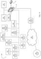
- the depth adjustment actuators/motors may be in data communication with a depth control and the soil monitoring system 300 as illustrated in FIG. 11 and described herein.
- a monitor 50 is in electrical communication with components associated with each row unit 10 including seed meter drives 315, seed sensors 305, the GPS receiver 53, downforce sensors 392, downforce valves 390, depth adjustment actuators 380, and depth actuator encoders 382 (and in some embodiments actual depth sensors 385 such as those described in applicant' s U.S. Patent Application Publication Number 2015/0298438 ).
- the monitor 50 may be in electrical communication with clutches 310 configured to selectively operably couple the seed meter 30 to the drive 315.
- the monitor 50 may be in electrical communication with a cellular modem 330 or other component configured to place the monitor 50 in data communication with the Internet, indicated by reference numeral 335. Via the Internet connection, the monitor 50 may receive data from a soil data server 345.
- the soil data server 345 may include soil map files (e.g., shape files) associating soil types (or other soil characteristics) with GPS locations. In some embodiments, soil map files are stored in the memory of the monitor 50.
- the monitor 50 may also be in electrical communication with one or more temperature sensors 360 mounted to the planter and configured to generate a signal related to the temperature of soil being worked by the planter row units 10.
- one or more of the temperature sensors 360 comprise thermocouples disposed to engage the soil as disclosed in Applicant's International Patent Pub. No. WO2014/153157 .
- the temperature sensors 360 engage the soil at the bottom of the trench 3.
- one or more of the temperature sensors 360 may comprise a sensor disposed and configured to measure the temperature of the soil without contacting the soil.
- the monitor 50 may be in electrical communication with one or more moisture sensors 350 mounted to the planter and configured to generate a signal related to the temperature of soil being worked by the planter row units 10.
- the moisture sensor 350 comprises a reflectance sensor such as that disclosed in U. S. Patent no. 8,204,689 .
- the moisture sensor 350 may be mounted to the shank 15 of the row unit 10 and disposed to measure the soil moisture at the bottom of the trench 3, which may be at a position longitudinally forward of the seed tube 32.
- the monitor 50 may be in electrical communication with one or more second-depth moisture sensors 352.
- the second-depth moisture sensor 352 may comprise a reflectance sensor such as that disclosed in the '689 patent, disposed to measure soil moisture at a depth at which consistent moisture reading is expected. In some embodiments the second-depth moisture sensor 352 is disposed to measure soil moisture at a greater depth than used for planting, such as between 3 and 6 inches and preferably approximately 4 inches below the soil surface. In other embodiments the second-depth moisture sensor 352 is disposed to measure soil moisture at a lesser depth than used for planting, such as between 0.25 inch and 1 inch and preferably approximately 0.5 inches below the soil surface. The second-depth moisture sensor 352 may be disposed to open a trench laterally offset from the trenches 3 opened by the row units 10.
- the monitor 50 may be in electrical communication with one or more electrical conductivity sensors 365.
- the electrical conductivity sensor 365 preferably comprises one or more electrodes disposed to cut into the soil surface such as the sensors disclosed in U. S. Patents nos. 5,841,282 and 5,524,560 .
- the monitor 50 may also be in electrical communication with one or more pH sensors 355.
- the pH sensor 355 is drawn by a tractor or by another implement (e.g., a tillage implement) such that data is stored in the monitor 50 for later use.
- the pH sensor 355 is similar to that disclosed in U. S. Patent no. 6,356,830 .
- the pH sensor 355 may be mounted to the toolbar 8, such as at a position laterally offset from the row units 10.
- a user may manually adjust the primary and/or secondary depth adjustment assemblies.
- the user may manually adjust the primary depth adjustment assembly and use the monitor 50 to command a depth adjustment to the secondary depth adjustment assembly.
- the user may manually adjust the primary depth adjustment assembly and the monitor 50 may command a desired depth adjustment to the secondary depth adjustment assembly (e.g., one of the actuators/motors 720, 800, 950, 1000, 1230, 1450, 1550, 1650, 1750, 1850, 1950, 1984) by receiving one or more agronomic variables from the sensors (e.g., sensors 350, 355, 360, 365, 352, 385) or from the soil data server 345 and determining a desired depth adjustment by consulting a database or algorithm relating one or more agronomic variables to a desired furrow depth.
- the sensors e.g., sensors 350, 355, 360, 365, 352, 385
- the soil data server 345 e.g., determining a desired depth adjustment by consulting a database or algorithm relating one or more agronomic variables to a desired furrow depth.
- the monitor 50 may command a desired depth adjustment to the primary depth adjustment assembly and/or to the secondary depth adjustment assembly (e.g., one of the actuators/motors 720, 800, 950, 1000, 1230, 1450, 1550, 1650, 1750, 1850, 1950, 1984) by receiving one or more agronomic variables from the sensors (e.g., sensors 350, 355, 360, 365, 352, 385) or from the soil data server 345 and determining a desired depth adjustment by consulting a database or algorithm relating one or more agronomic variables to a desired furrow depth.
- the sensors e.g., sensors 350, 355, 360, 365, 352, 385
- the soil data server 345 e.g., determining a desired depth adjustment by consulting a database or algorithm relating one or more agronomic variables to a desired furrow depth.
- the monitor 50 may command a desired depth adjustment to the primary depth adjustment assembly and/or to the secondary depth adjustment assembly (e.g., one of the actuators/motors 720, 800, 950, 1000, 1230, 1450, 1550, 1650, 1750, 1850, 1950, 1984) by determining the GPS-reported location of the row unit 10 and consulting a depth prescription map spatially relating locations and/or regions in the field to desired furrow depths.
- a desired depth adjustment to the primary depth adjustment assembly and/or to the secondary depth adjustment assembly e.g., one of the actuators/motors 720, 800, 950, 1000, 1230, 1450, 1550, 1650, 1750, 1850, 1950, 1984
- the monitor 50 may record changes in depth in the field by associating commanded actuations of the actuator/motor 720, 800, 950, 1000, 1230, 1450, 1550, 1650, 1750, 1850, 1950, 1984 with GPS locations reported by the GPS receiver 53. In some such embodiments, the monitor 50 may record a change in depth concurrently with the commanded actuations of the actuator/motor 720, 800, 950, 1000, 1230, 1450, 1550, 1650, 1750, 1850, 1950.
- the force between the rocker 95 and the gauge wheel arm and/or the depth adjustment member may vary, e.g., as the row unit moves across uneven terrain.
- the monitor 50 may monitor the force on the gauge wheel arm and/or the depth adjustment rocker and record the change in depth only when the force is lower than a predetermined threshold.
- the monitor 50 may monitor the force on the gauge wheel arm and/or the depth adjustment rocker and record the change in depth only when the force is lower than a predetermined threshold at which the depth adjustment member can be advanced for a given position of the actuator 1230.
- the force on the gauge wheel arm and/or the depth adjustment rocker may be recorded by a load sensor such as a strain gauge mounted to the gauge wheel arm or other location through which the force is transmitted, or by a load sensing pin incorporated in the row unit as is known in the art.
- the monitor 50 may command a temporary change (e.g., reduction) in row unit downforce applied by the actuator 18 concurrently with (or before or after) a commanded change in the extension of the actuator/motor 720, 800, 950, 1000, 1230, 1450, 1550, 1650, 1750, 1850, 1950, 1984 in order to permit the depth adjustment.
- the monitor 50 then preferably commands the row unit downforce applied by the actuator 18 to return to its previously commanded level.
- An agricultural trench depth sensing system comprising:
- Aspect 2 The agricultural trench depth sensing system of aspect 1, wherein said light source, said receiver and said sensor are disposed in a single body mounted to a frame member of said agricultural row unit.
- Aspect 3 The agricultural trench depth sensing system of aspect 1, wherein said light source, said receiver and said sensor are separately disposed and supported on said row unit rearward of said opening disc.
- Aspect 4 The agricultural trench depth sensing system of aspect 1, wherein said light source, said receiver and said sensor are mounted on an appurtenance supported from a frame member of said row unit, said appurtenance extending rearwardly from said opening disc and longitudinally aligned with said trench.
- Aspect 5 The agricultural trench depth sensing system of aspect 4, wherein said appurtenance is a seed firmer, said seed firmer having a ground engaging portion disposed in said trench.
- Aspect 6 The agricultural trench depth sensing system of aspect 5, wherein said light source and said receiver are disposed on an underside of said seed firmer.
- Aspect 7 The agricultural trench depth sensing system of aspect 5, wherein said light source is disposed over said seed firmer directing light downwardly toward said soil surface and into said trench and said receiver disposed on an underside of said seed firmer.
- Aspect 8 The agricultural trench depth sensing system of aspect 5, wherein said light source includes a first light source and a second light source, said first light source disposed over said seed firmer directing light downwardly toward said soil surface on at least one side of said trench, said second light source disposed on an underside of said seed firmer directing light into said trench, said receiver disposed on an underside of said seed firmer and disposed to receive said reflected light from said first light source and said second light source.
- Aspect 9 The agricultural trench depth sensing system of aspect 1, wherein said monitoring system is configured to display a spatial map of said measured depths of said trench as said agricultural row unit advances through said field.
- Aspect 10 The agricultural trench depth sensing system of aspect 1, further comprising:
- Aspect 11 The agricultural trench depth sensing system of aspect 1, further comprising:
- Aspect 12 The agricultural trench depth sensing system of aspect 1, wherein said light from said light source is modulated to produce light of different wavelengths, whereby said data frame contains triangulated line patterns and intensity values of said different wavelengths of said reflected light along said triangulated line pattern, and whereby a relationship between said triangulated line patterns and said intensity values along said triangulated line pattern is indicative of at least one of: (i) uniformity of said trench; (ii) relative soil moisture versus trench depth; (iii) presence of dry topsoil in said trench; (iv) presence of residue in said trench; (v) presence of a seed in said trench; (vi) a depth of said seed in said trench; and (vii) depth of gauge wheels relative to full trench depth.
- Aspect 13 The agricultural trench depth sensing system of aspect 12, wherein said monitoring system is configured to generate a profile of said trench based on said generated data frame.
- Aspect 14 The agricultural trench depth sensing system of aspect 12, wherein said monitoring system is configured to display a spatial map of seed depth as said agricultural row unit advances through said field.
- Aspect 15 The agricultural trench depth sensing system of aspect 12, further comprising:
- Aspect 16 The agricultural trench depth sensing system of aspect 14, further comprising:
- Aspect 17 The agricultural trench depth sensing system of aspect 12, further comprising:
- Aspect 18 The agricultural trench depth sensing system of aspect 12, further comprising:
- Aspect 19 The agricultural trench depth sensing system of aspect 12, wherein a first image is generated based on said reflected light of a first wavelength of said different wavelengths, and wherein a second image is generated based on said reflected light of a second wavelength of said different wavelengths, and wherein a third image is generated when said light source is off; whereby said monitoring system generates a first net image pattern by subtracting said third image from said first image, and said monitoring system generates a second net image pattern by subtracting said third image from said second image.
- Aspect 20 The agricultural trench depth sensing system of aspect 19, wherein said uniformity of said trench is determined by comparing said first net image pattern or said second net image pattern to a trench profile curve.
- Aspect 21 The agricultural trench depth sensing system of aspect 19, wherein said uniformity of said trench is determined by comparing said first net image pattern to said second net image pattern.
- Aspect 22 The agricultural trench depth sensing system of aspect 19, wherein said uniformity of said trench is determined by calculating a standard deviation from a trench profile curve and averaged between the first net image pattern and the second net image pattern.
- a method of determining depth of a trench formed in a soil surface by an opening disc of an agricultural row unit as the agricultural row unit advances in a forward direction of travel through a field comprising:
- Aspect 24 The method of aspect 23, wherein said light source and said receiver are disposed in a single body mounted to a frame member of the agricultural row unit.
- Aspect 25 The method of aspect 23, wherein said light source and said receiver are separately disposed and supported on the agricultural row unit rearward of the opening disc.
- Aspect 26 The method of aspect 23, wherein said light source, said receiver and said sensor are mounted on an appurtenance supported from a frame member of the row unit, said appurtenance extending rearwardly from the opening disc and longitudinally aligned with the trench.
- Aspect 27 The method of aspect 26, wherein said appurtenance is a seed firmer, said seed firmer having a ground engaging portion disposed in the trench.
- Aspect 28 The method of aspect 27, wherein said light source and said receiver are disposed on an underside of said seed firmer.
- Aspect 29 The method of aspect 27, wherein said light source is disposed over said seed firmer directing light downwardly toward said soil surface and into the trench and said receiver disposed on an underside of said seed firmer.
- Aspect 30 The method of aspect 27, wherein said light source includes a first light source and a second light source, said first light source disposed over said seed firmer directing light downwardly toward said soil surface on at least one side of the trench, said second light source disposed on an underside of said seed firmer directing light into the trench, said receiver disposed on an underside of said seed firmer and disposed to receive said reflected light from said first light source and said second light source.
- Aspect 31 The method of aspect 23, further comprising: displaying a spatial map of said measured depths of the trench as the agricultural row unit advances through the field.
- Aspect 32 The method of aspect 23, further comprising: actuating a downforce actuator to adjust downforce applied to the agricultural row unit based on said measured depths.
- Aspect 33 The method of aspect 23, further comprising: adjusting a depth control actuator to adjust a depth of the trench based on said measured depth.
- Aspect 34 The method of aspect 23, further comprising: modulating said light source to produce light of different wavelengths, whereby said data frame contains triangulated line patterns and intensity values of said different wavelengths of said reflected light along said triangulated line pattern.
- Aspect 35 The method of aspect 34, further comprising: determining at least one of the following characteristics of the trench based on relationship between said triangulated line patterns and said intensity values along said triangulated line pattern: (i) uniformity of the trench; (ii) relative soil moisture versus trench depth; (iii) presence of dry topsoil in the trench; (iv) presence of residue in the trench; (v) presence of a seed in the trench; (vi) a depth of said seed in the trench; and (vii) depth of gauge wheels relative to full trench depth.
- Aspect 36 The method of aspect 34, further comprising: generating a profile of the trench, based on said generated data frame.
- Aspect 37 The method of aspect 34, further comprising: displaying a spatial map of seed depth as the agricultural row unit advances through the field.
- Aspect 38 The method of aspect 35, further comprising: actuating a depth control actuator to adjust depth of the trench based on said determination of said presence of dry topsoil soil in said trench.
- Aspect 39 The method of aspect 35, further comprising: actuating a depth adjustment actuator to adjust depth of the trench based on said determination of said seed depth in relation to said relative soil moisture.
- Aspect 40 The method of aspect 35, further comprising: actuating a row cleaner actuator to adjust downforce applied by said row cleaner actuator to said row cleaner based on said determination of said presence of residue in said trench.
- Aspect 41 The method of aspect 35, further comprising: based on the determination of the presence of the seeds in the trench, opening a valve to release liquid from a liquid source relative to said seeds such that said liquid is placed either on said seeds, between said seeds or adjacent to said seeds.
- Aspect 42 The method of aspect 34, further comprising:
- Aspect 43 The method of aspect 35, further comprising: comparing said first net image pattern or said second net image pattern to a trench profile curve to determine said uniformity of the trench.
- Aspect 44 The method of aspect 35, further comprising: comparing said first net image pattern to said second net image pattern to determine said uniformity of the trench.
- Aspect 45 The method of aspect 35, further comprising: calculating a standard deviation from a trench profile curve averaged between the first net image pattern and the second net image pattern to determine said uniformity of the trench.
Landscapes
- Life Sciences & Earth Sciences (AREA)
- Soil Sciences (AREA)
- Environmental Sciences (AREA)
- Engineering & Computer Science (AREA)
- Mechanical Engineering (AREA)
- Physics & Mathematics (AREA)
- General Physics & Mathematics (AREA)
- Water Supply & Treatment (AREA)
- Management, Administration, Business Operations System, And Electronic Commerce (AREA)
- Pretreatment Of Seeds And Plants (AREA)
- Investigating Or Analysing Materials By Optical Means (AREA)
- Sowing (AREA)
Applications Claiming Priority (3)
| Application Number | Priority Date | Filing Date | Title |
|---|---|---|---|
| US201862722386P | 2018-08-24 | 2018-08-24 | |
| PCT/IB2019/056949 WO2020039322A1 (fr) | 2018-08-24 | 2019-08-16 | Systèmes, procédés, et appareil de détection de profondeur de tranchée agricole |
| EP19790056.6A EP3840561B1 (fr) | 2018-08-24 | 2019-08-16 | Système et procédé de détection de profondeur de tranchée agricole |
Related Parent Applications (2)
| Application Number | Title | Priority Date | Filing Date |
|---|---|---|---|
| EP19790056.6A Division EP3840561B1 (fr) | 2018-08-24 | 2019-08-16 | Système et procédé de détection de profondeur de tranchée agricole |
| EP19790056.6A Division-Into EP3840561B1 (fr) | 2018-08-24 | 2019-08-16 | Système et procédé de détection de profondeur de tranchée agricole |
Publications (2)
| Publication Number | Publication Date |
|---|---|
| EP4223096A2 true EP4223096A2 (fr) | 2023-08-09 |
| EP4223096A3 EP4223096A3 (fr) | 2023-10-18 |
Family
ID=68290013
Family Applications (2)
| Application Number | Title | Priority Date | Filing Date |
|---|---|---|---|
| EP19790056.6A Active EP3840561B1 (fr) | 2018-08-24 | 2019-08-16 | Système et procédé de détection de profondeur de tranchée agricole |
| EP23166570.4A Pending EP4223096A3 (fr) | 2018-08-24 | 2019-08-16 | Systèmes, procédés et appareil de détection de tranchée agricole |
Family Applications Before (1)
| Application Number | Title | Priority Date | Filing Date |
|---|---|---|---|
| EP19790056.6A Active EP3840561B1 (fr) | 2018-08-24 | 2019-08-16 | Système et procédé de détection de profondeur de tranchée agricole |
Country Status (7)
| Country | Link |
|---|---|
| US (3) | US12256656B2 (fr) |
| EP (2) | EP3840561B1 (fr) |
| CN (1) | CN112601450B (fr) |
| AR (2) | AR116014A1 (fr) |
| AU (3) | AU2019326066B2 (fr) |
| WO (1) | WO2020039322A1 (fr) |
| ZA (1) | ZA202100754B (fr) |
Families Citing this family (41)
| Publication number | Priority date | Publication date | Assignee | Title |
|---|---|---|---|---|
| AR113306A1 (es) | 2017-10-03 | 2020-04-08 | Ag Leader Tech | Aparato dosificador de impulsos de aire controlados para una sembradora agrícola y sistemas y métodos relacionados |
| US11277961B2 (en) | 2018-02-09 | 2022-03-22 | Ag Leader Technology | Seed spacing device for an agricultural planter and related systems and methods |
| US10813281B2 (en) | 2018-02-20 | 2020-10-27 | Ag Leader Technology | Apparatus, systems and methods for applying fluid |
| US20190297769A1 (en) | 2018-03-30 | 2019-10-03 | Ag Leader Technology | Devices, Systems, and Methods for Seed Trench Protection |
| CN112601450B (zh) | 2018-08-24 | 2024-12-06 | 精密种植有限责任公司 | 农业沟道深度感测系统、方法和装置 |
| US12520744B2 (en) | 2018-11-15 | 2026-01-13 | Ag Leader Technology | On the go organic matter sensor and associated systems and methods |
| US11523554B2 (en) | 2019-01-25 | 2022-12-13 | Ag Leader Technology | Dual seed meter and related systems and methods |
| US11785881B2 (en) | 2019-08-19 | 2023-10-17 | Ag Leader Technology | Adjustable seed meter and related systems and methods |
| US11419254B2 (en) * | 2019-10-28 | 2022-08-23 | Cnh Industrial Canada, Ltd. | System and method for detecting levelness of tools of a tillage implement based on tool loading |
| US11523556B2 (en) | 2019-12-24 | 2022-12-13 | Cnh Industrial America Llc | Particle delivery system of an agricultural row unit |
| US11483963B2 (en) | 2019-12-24 | 2022-11-01 | Cnh Industrial America Llc | Particle delivery system of an agricultural row unit |
| US11582899B2 (en) | 2019-12-24 | 2023-02-21 | Cnh Industrial America Llc | Particle delivery system of an agricultural row unit |
| US11553638B2 (en) | 2019-12-24 | 2023-01-17 | Cnh Industrial America Llc | Particle delivery system of an agricultural row unit |
| US11490558B2 (en) | 2019-12-24 | 2022-11-08 | Cnh Industrial America Llc | Particle delivery system of an agricultural row unit |
| US11596095B2 (en) | 2019-12-24 | 2023-03-07 | Cnh Industrial America Llc | Particle delivery system of an agricultural row unit |
| US11523555B2 (en) | 2019-12-24 | 2022-12-13 | Cnh Industrial America Llc | Particle delivery system of an agricultural row unit |
| US11564346B2 (en) | 2019-12-24 | 2023-01-31 | Cnh Industrial America Llc | Particle delivery system of an agricultural row unit |
| US11553639B2 (en) | 2019-12-24 | 2023-01-17 | Cnh Industrial America Llc | Particle delivery system of an agricultural row unit |
| US11564344B2 (en) | 2019-12-24 | 2023-01-31 | Cnh Industrial America Llc | Particle delivery system of an agricultural row unit |
| US11516958B2 (en) | 2019-12-24 | 2022-12-06 | Cnh Industrial America Llc | Particle delivery system of an agricultural row unit |
| US11589500B2 (en) | 2019-12-24 | 2023-02-28 | Cnh Industrial America Llc | Particle delivery system of an agricultural row unit |
| US12268115B2 (en) | 2020-02-07 | 2025-04-08 | Ag Leader Technology | Planter obstruction monitoring and associated devices and methods |
| US11558993B2 (en) * | 2020-03-26 | 2023-01-24 | Cnh Industrial America Llc | Soil monitoring system for an agricultural tillage implement |
| US12564121B2 (en) * | 2020-07-01 | 2026-03-03 | Deere & Company | Implement mounted sensors sensing surface/furrow characteristics and control |
| US12477973B2 (en) | 2020-11-13 | 2025-11-25 | Ag Leader Technology | Agricultural high speed row unit |
| US12256657B2 (en) | 2021-01-25 | 2025-03-25 | Deere & Company | Implement mounted sensors sensing seed and residue characteristics and control |
| US11669592B2 (en) | 2021-02-12 | 2023-06-06 | Cnh Industrial America Llc | Systems and methods for residue bunch detection |
| US11538180B2 (en) | 2021-02-12 | 2022-12-27 | Cnh Industrial Canada, Ltd. | Systems and methods for determining residue length within a field |
| US12342739B2 (en) | 2021-02-17 | 2025-07-01 | Cnh Industrial America Llc | System and method for controlling the operation of a row cleaning device of a seed-planting implement |
| US12075718B2 (en) | 2021-02-17 | 2024-09-03 | Cnh Industrial America Llc | System and method for controlling the operation of a row cleaning device of a seed-planting implement |
| AU2022327711B2 (en) * | 2021-08-11 | 2026-04-16 | Precision Planting Llc | Method and systems for using sensors to determine characteristics of seeds or particles |
| SE548189C2 (en) * | 2021-12-16 | 2026-04-15 | Vaederstad Holding Ab | Row unit for agricultural implement, agricultural implement comprising closing wheel and method of adjusting closing wheel |
| WO2023158569A1 (fr) * | 2022-02-08 | 2023-08-24 | Deere & Company | Mesure de profil de tranchée basée sur une lumière structurée pour élément semeur en rangée |
| EP4422383A4 (fr) * | 2022-02-08 | 2025-11-19 | Deere & Co | Mesure de profil de tranchée basée sur une lumière structurée pour élément semeur en rangée |
| US20240040952A1 (en) * | 2022-08-03 | 2024-02-08 | Veris Technologies, Inc. | Agricultural implement with sensors for measuring soil properties |
| US12536695B2 (en) * | 2022-08-31 | 2026-01-27 | Deere & Company | Trench profile determination by motion |
| US20250040475A1 (en) * | 2022-12-20 | 2025-02-06 | Deere & Company | Camera driven section control delay |
| US20240303839A1 (en) * | 2023-03-09 | 2024-09-12 | Deere & Company | Agricultural camera confidence |
| CA3244669A1 (en) * | 2023-07-31 | 2025-06-09 | Deere & Company | Camera driven section control delay |
| US20250113765A1 (en) * | 2023-10-04 | 2025-04-10 | Deere & Company | Generating prescriptive depth values based on soil environment and controlling an actuator to vary planting depth based on the prescriptive depth values |
| CN119866711B (zh) * | 2025-03-17 | 2025-07-11 | 中国科学院沈阳应用生态研究所 | 基于土壤温湿度的秸秆还田深松耕作调控方法 |
Citations (15)
| Publication number | Priority date | Publication date | Assignee | Title |
|---|---|---|---|---|
| US5524560A (en) | 1994-12-09 | 1996-06-11 | The United States Of America As Represented By The Department Of Agriculture | System for controlling vertical displacement of agricultural implements into the soil |
| US5841282A (en) | 1997-02-10 | 1998-11-24 | Christy; Colin | Device for measuring soil conductivity |
| US6356830B1 (en) | 1998-08-11 | 2002-03-12 | Purdue Research Foundation | System and method for automated measurement of soil pH |
| US7370589B2 (en) | 2003-04-24 | 2008-05-13 | University Of Tennessee Research Foundation | Systems and methods for fluid dispensing |
| US8204689B2 (en) | 2007-10-24 | 2012-06-19 | Veris Technologies, Inc. | Mobile soil mapping system for collecting soil reflectance measurements |
| WO2012129442A2 (fr) | 2011-03-22 | 2012-09-27 | Precision Planting, Inc. | Dispositif de mesure de graines |
| US8550020B2 (en) | 2010-12-16 | 2013-10-08 | Precision Planting Llc | Variable pressure control system for dual acting actuators |
| WO2014066650A1 (fr) | 2012-10-24 | 2014-05-01 | Precision Planting Llc | Systèmes, procédés et appareil de fermeture de tranchée agricole |
| WO2014153157A1 (fr) | 2013-03-14 | 2014-09-25 | Precision Planting Llc | Systèmes, procédés et appareil pour régulation de profondeur de sillon d'instruments agricoles et surveillance du sol |
| US20150298438A1 (en) | 2012-11-30 | 2015-10-22 | Stora Enso Oyj | A method for manufacturing a packaging material |
| WO2015171908A1 (fr) | 2014-05-08 | 2015-11-12 | Precision Planting Llc | Systèmes, procédés et appareils de surveillance du sol et des semences |
| WO2017143125A1 (fr) | 2016-02-19 | 2017-08-24 | Precision Planting Llc | Systèmes, procédés et appareil de profondeur de tranchée agricole |
| WO2017197292A1 (fr) | 2016-05-13 | 2017-11-16 | Precision Planting Llc | Systèmes de détection de profondeur de sillon de semis |
| WO2018018050A1 (fr) | 2016-07-22 | 2018-01-25 | Precision Planting Llc | Systèmes, procédés et appareil de détection de profondeur de tranchée agricole |
| US20180168094A1 (en) | 2016-12-19 | 2018-06-21 | The Climate Corporation | Systems, methods, and apparatus for soil and seed monitoring |
Family Cites Families (32)
| Publication number | Priority date | Publication date | Assignee | Title |
|---|---|---|---|---|
| US9743574B1 (en) | 2007-10-24 | 2017-08-29 | Veris Technologies, Inc. | Mobile soil optical mapping system |
| US8843281B2 (en) * | 2010-09-17 | 2014-09-23 | Kinze Manufacturing, Inc. | Seed characteristic sensor |
| US9743578B2 (en) * | 2011-04-27 | 2017-08-29 | Kinze Manufacturing, Inc. | Agricultural devices, systems, and methods for determining soil and seed characteristics and analyzing the same |
| US8935986B2 (en) | 2011-04-27 | 2015-01-20 | Kinze Manufacturing, Inc. | Agricultural devices, systems, and methods for determining soil and seed characteristics and analyzing the same |
| US8869629B2 (en) * | 2012-03-08 | 2014-10-28 | Cnh Industrial Canada, Ltd. | System and method for monitoring agricultural product delivery |
| DE102012203761A1 (de) | 2012-03-09 | 2013-09-12 | Deere & Company | Anordnung und Verfahren zur Präzisionsaussaat von Saatkörnern |
| US9113590B2 (en) | 2012-08-06 | 2015-08-25 | Superior Edge, Inc. | Methods, apparatus, and systems for determining in-season crop status in an agricultural crop and alerting users |
| EP3656196B1 (fr) | 2012-10-24 | 2022-08-03 | Precision Planting LLC | Appareil de détection de profondeur de tranchées agricoles |
| EP2972252B1 (fr) * | 2013-03-14 | 2023-10-18 | Robert Ernest Troxler | Systèmes et procédés permettant de mesurer les propriétés d'ensemble d'une chaussée et l'humidité d'un sol au moyen d'un géoradar |
| US9629304B2 (en) | 2013-04-08 | 2017-04-25 | Ag Leader Technology | On-the go soil sensors and control methods for agricultural machines |
| US8849523B1 (en) * | 2013-05-20 | 2014-09-30 | Elwha Llc | Systems and methods for detecting soil characteristics |
| US9401030B2 (en) * | 2014-04-25 | 2016-07-26 | Tazco Soil Service Co. | Image processing system for soil characterization |
| EP3295224B1 (fr) * | 2015-05-08 | 2020-09-02 | The Climate Corporation | Imagerie et analyse de couche de travail pour surveillance d'outil, commande et retour d'informations à l'opérateur |
| EP4241550A3 (fr) | 2015-06-15 | 2023-11-15 | Precision Planting LLC | Systèmes, procédés et appareil pour application de liquide agricole |
| US10681861B2 (en) | 2015-06-15 | 2020-06-16 | The Climate Corporation | Agricultural operation monitoring apparatus, systems and methods |
| US9693496B2 (en) * | 2015-09-30 | 2017-07-04 | Deere & Company | Agricultural planting depth sensor |
| US10462956B2 (en) | 2016-06-28 | 2019-11-05 | Agco Corporation | Down force control to allow for easier depth adjustment |
| US11516959B2 (en) * | 2017-07-24 | 2022-12-06 | Precision Planting, Llc | Agricultural trench depth sensing systems, methods, and apparatus |
| AU2017355315B2 (en) * | 2016-11-07 | 2023-12-14 | Climate Llc | Work layer imaging and analysis for implement monitoring, control and operator feedback |
| US10867377B2 (en) * | 2016-12-21 | 2020-12-15 | Massachusetts Institute Of Technology | Determining soil state and controlling equipment based on captured images |
| US10257973B2 (en) | 2017-02-14 | 2019-04-16 | Deere & Company | Row planter unit with sensor-mounted furrow shaper |
| EP3434091B1 (fr) | 2017-07-27 | 2020-02-12 | Baumer Electric AG | Dispositif capteur pour déterminer la position de graines pendant l'ensemencement, système d'ensemencement et procédé permettant de déterminer la position de graines dans une tranchée |
| WO2019079205A1 (fr) * | 2017-10-17 | 2019-04-25 | Precision Planting Llc | Systèmes de détection de sol et instruments de détection de différents paramètres pédologiques |
| US20190254223A1 (en) | 2018-02-19 | 2019-08-22 | Ag Leader Technology | Planter Downforce And Uplift Monitoring And Control Feedback Devices, Systems And Associated Methods |
| US20250113761A1 (en) | 2018-06-07 | 2025-04-10 | Precision Planting Llc | Agricultural operation monitoring apparatus, systems and methods |
| US20190373801A1 (en) | 2018-06-12 | 2019-12-12 | Cnh Industrial America Llc | Adjustable closing system |
| CN112601450B (zh) | 2018-08-24 | 2024-12-06 | 精密种植有限责任公司 | 农业沟道深度感测系统、方法和装置 |
| US10986766B2 (en) | 2018-10-05 | 2021-04-27 | Cnh Industrial America Llc | System and related methods for monitoring and adjusting actual seed depths during a planting operation based on soil moisture content |
| EP3965544B1 (fr) | 2019-05-10 | 2024-11-27 | Great Plains Manufacturing, Inc. | Système de contrôl pour outils agricoles et procédé |
| US20210027449A1 (en) * | 2019-07-23 | 2021-01-28 | Cnh Industrial America Llc | System and method for determining field characteristics based on data from multiple types of sensors |
| US11832545B2 (en) * | 2019-12-31 | 2023-12-05 | Cnh Industrial America Llc | System and method for operating ground engaging tools based on measured soil moisture |
| US12564121B2 (en) | 2020-07-01 | 2026-03-03 | Deere & Company | Implement mounted sensors sensing surface/furrow characteristics and control |
-
2019
- 2019-08-16 CN CN201980055838.1A patent/CN112601450B/zh active Active
- 2019-08-16 US US17/270,198 patent/US12256656B2/en active Active
- 2019-08-16 EP EP19790056.6A patent/EP3840561B1/fr active Active
- 2019-08-16 WO PCT/IB2019/056949 patent/WO2020039322A1/fr not_active Ceased
- 2019-08-16 EP EP23166570.4A patent/EP4223096A3/fr active Pending
- 2019-08-16 AU AU2019326066A patent/AU2019326066B2/en active Active
- 2019-08-23 AR ARP190102414A patent/AR116014A1/es active IP Right Grant
-
2021
- 2021-02-03 ZA ZA2021/00754A patent/ZA202100754B/en unknown
-
2023
- 2023-01-04 US US18/149,975 patent/US12369514B2/en active Active
- 2023-09-19 AR ARP230102489A patent/AR130522A2/es unknown
-
2024
- 2024-11-21 US US18/955,090 patent/US20250081875A1/en active Pending
-
2025
- 2025-06-20 AU AU2025204683A patent/AU2025204683B2/en active Active
-
2026
- 2026-02-26 AU AU2026201495A patent/AU2026201495A1/en active Pending
Patent Citations (16)
| Publication number | Priority date | Publication date | Assignee | Title |
|---|---|---|---|---|
| US5524560A (en) | 1994-12-09 | 1996-06-11 | The United States Of America As Represented By The Department Of Agriculture | System for controlling vertical displacement of agricultural implements into the soil |
| US5841282A (en) | 1997-02-10 | 1998-11-24 | Christy; Colin | Device for measuring soil conductivity |
| US6356830B1 (en) | 1998-08-11 | 2002-03-12 | Purdue Research Foundation | System and method for automated measurement of soil pH |
| US7370589B2 (en) | 2003-04-24 | 2008-05-13 | University Of Tennessee Research Foundation | Systems and methods for fluid dispensing |
| US8204689B2 (en) | 2007-10-24 | 2012-06-19 | Veris Technologies, Inc. | Mobile soil mapping system for collecting soil reflectance measurements |
| US8550020B2 (en) | 2010-12-16 | 2013-10-08 | Precision Planting Llc | Variable pressure control system for dual acting actuators |
| WO2012129442A2 (fr) | 2011-03-22 | 2012-09-27 | Precision Planting, Inc. | Dispositif de mesure de graines |
| WO2014066650A1 (fr) | 2012-10-24 | 2014-05-01 | Precision Planting Llc | Systèmes, procédés et appareil de fermeture de tranchée agricole |
| US20150298438A1 (en) | 2012-11-30 | 2015-10-22 | Stora Enso Oyj | A method for manufacturing a packaging material |
| WO2014153157A1 (fr) | 2013-03-14 | 2014-09-25 | Precision Planting Llc | Systèmes, procédés et appareil pour régulation de profondeur de sillon d'instruments agricoles et surveillance du sol |
| WO2015171908A1 (fr) | 2014-05-08 | 2015-11-12 | Precision Planting Llc | Systèmes, procédés et appareils de surveillance du sol et des semences |
| WO2015171915A1 (fr) | 2014-05-08 | 2015-11-12 | Precision Planting Llc | Systèmes, procédés et appareil pour application de liquide agricole |
| WO2017143125A1 (fr) | 2016-02-19 | 2017-08-24 | Precision Planting Llc | Systèmes, procédés et appareil de profondeur de tranchée agricole |
| WO2017197292A1 (fr) | 2016-05-13 | 2017-11-16 | Precision Planting Llc | Systèmes de détection de profondeur de sillon de semis |
| WO2018018050A1 (fr) | 2016-07-22 | 2018-01-25 | Precision Planting Llc | Systèmes, procédés et appareil de détection de profondeur de tranchée agricole |
| US20180168094A1 (en) | 2016-12-19 | 2018-06-21 | The Climate Corporation | Systems, methods, and apparatus for soil and seed monitoring |
Also Published As
| Publication number | Publication date |
|---|---|
| US20230189691A1 (en) | 2023-06-22 |
| AU2025204683A1 (en) | 2025-07-10 |
| CN112601450A (zh) | 2021-04-02 |
| US12256656B2 (en) | 2025-03-25 |
| BR112021003070A2 (pt) | 2021-05-11 |
| EP3840561A1 (fr) | 2021-06-30 |
| WO2020039322A1 (fr) | 2020-02-27 |
| US12369514B2 (en) | 2025-07-29 |
| AU2019326066A1 (en) | 2021-03-11 |
| EP3840561B1 (fr) | 2023-06-07 |
| EP4223096A3 (fr) | 2023-10-18 |
| CN112601450B (zh) | 2024-12-06 |
| US20250081875A1 (en) | 2025-03-13 |
| AR130522A2 (es) | 2024-12-11 |
| AU2025204683B2 (en) | 2026-02-05 |
| AU2019326066B2 (en) | 2025-03-27 |
| CA3108433A1 (fr) | 2020-02-27 |
| AR116014A1 (es) | 2021-03-25 |
| US20210307236A1 (en) | 2021-10-07 |
| AU2026201495A1 (en) | 2026-03-19 |
| ZA202100754B (en) | 2024-09-25 |
Similar Documents
| Publication | Publication Date | Title |
|---|---|---|
| AU2025204683B2 (en) | Agricultural trench depth sensing systems, methods, and apparatus | |
| US20250000009A1 (en) | Agricultural operation monitoring apparatus, systems and methods | |
| US12329059B2 (en) | Agricultural operation monitoring apparatus, systems, and methods | |
| US12274193B2 (en) | Systems, apparatuses, and methods for monitoring soil characteristics and determining soil color | |
| US20230371419A1 (en) | Systems and apparatuses for soil and seed monitoring | |
| RU2720278C2 (ru) | Устройство, система и способ мониторинга критериев почвы во время операций обработки почвы и управление почвообрабатывающими рабочими органами | |
| US10681861B2 (en) | Agricultural operation monitoring apparatus, systems and methods | |
| CA3108433C (fr) | Systemes, procedes, et appareil de detection de profondeur de tranchee agricole | |
| BR112021003070B1 (pt) | Sistema de detecção de profundidade de sulco agrícola e método de usar o sistema | |
| RU2823622C2 (ru) | Почвообрабатывающий агрегат для обработки почвы, система и способ обработки почвы таким почвообрабатывающим агрегатом |
Legal Events
| Date | Code | Title | Description |
|---|---|---|---|
| PUAI | Public reference made under article 153(3) epc to a published international application that has entered the european phase |
Free format text: ORIGINAL CODE: 0009012 |
|
| STAA | Information on the status of an ep patent application or granted ep patent |
Free format text: STATUS: THE APPLICATION HAS BEEN PUBLISHED |
|
| AC | Divisional application: reference to earlier application |
Ref document number: 3840561 Country of ref document: EP Kind code of ref document: P |
|
| AK | Designated contracting states |
Kind code of ref document: A2 Designated state(s): AL AT BE BG CH CY CZ DE DK EE ES FI FR GB GR HR HU IE IS IT LI LT LU LV MC MK MT NL NO PL PT RO RS SE SI SK SM TR |
|
| PUAL | Search report despatched |
Free format text: ORIGINAL CODE: 0009013 |
|
| AK | Designated contracting states |
Kind code of ref document: A3 Designated state(s): AL AT BE BG CH CY CZ DE DK EE ES FI FR GB GR HR HU IE IS IT LI LT LU LV MC MK MT NL NO PL PT RO RS SE SI SK SM TR |
|
| RIC1 | Information provided on ipc code assigned before grant |
Ipc: A01C 21/00 20060101ALN20230912BHEP Ipc: G01B 11/22 20060101ALI20230912BHEP Ipc: A01C 7/10 20060101ALI20230912BHEP Ipc: A01C 23/02 20060101ALI20230912BHEP Ipc: A01C 7/20 20060101ALI20230912BHEP Ipc: A01C 7/06 20060101ALI20230912BHEP Ipc: A01C 7/00 20060101ALI20230912BHEP Ipc: A01B 79/00 20060101ALI20230912BHEP Ipc: A01C 5/06 20060101AFI20230912BHEP |
|
| STAA | Information on the status of an ep patent application or granted ep patent |
Free format text: STATUS: REQUEST FOR EXAMINATION WAS MADE |
|
| 17P | Request for examination filed |
Effective date: 20240418 |
|
| RBV | Designated contracting states (corrected) |
Designated state(s): AL AT BE BG CH CY CZ DE DK EE ES FI FR GB GR HR HU IE IS IT LI LT LU LV MC MK MT NL NO PL PT RO RS SE SI SK SM TR |
|
| STAA | Information on the status of an ep patent application or granted ep patent |
Free format text: STATUS: EXAMINATION IS IN PROGRESS |
|
| 17Q | First examination report despatched |
Effective date: 20250714 |