EP4223339B1 - Katheterstutzen mit saugport - Google Patents
Katheterstutzen mit saugport Download PDFInfo
- Publication number
- EP4223339B1 EP4223339B1 EP23165160.5A EP23165160A EP4223339B1 EP 4223339 B1 EP4223339 B1 EP 4223339B1 EP 23165160 A EP23165160 A EP 23165160A EP 4223339 B1 EP4223339 B1 EP 4223339B1
- Authority
- EP
- European Patent Office
- Prior art keywords
- catheter
- mount
- interface
- conduit
- valve
- Prior art date
- Legal status (The legal status is an assumption and is not a legal conclusion. Google has not performed a legal analysis and makes no representation as to the accuracy of the status listed.)
- Active
Links
Images












Classifications
-
- A—HUMAN NECESSITIES
- A61—MEDICAL OR VETERINARY SCIENCE; HYGIENE
- A61M—DEVICES FOR INTRODUCING MEDIA INTO, OR ONTO, THE BODY; DEVICES FOR TRANSDUCING BODY MEDIA OR FOR TAKING MEDIA FROM THE BODY; DEVICES FOR PRODUCING OR ENDING SLEEP OR STUPOR
- A61M16/00—Devices for influencing the respiratory system of patients by gas treatment, e.g. ventilators; Tracheal tubes
- A61M16/04—Tracheal tubes
- A61M16/0463—Tracheal tubes combined with suction tubes, catheters or the like; Outside connections
-
- A—HUMAN NECESSITIES
- A61—MEDICAL OR VETERINARY SCIENCE; HYGIENE
- A61M—DEVICES FOR INTRODUCING MEDIA INTO, OR ONTO, THE BODY; DEVICES FOR TRANSDUCING BODY MEDIA OR FOR TAKING MEDIA FROM THE BODY; DEVICES FOR PRODUCING OR ENDING SLEEP OR STUPOR
- A61M16/00—Devices for influencing the respiratory system of patients by gas treatment, e.g. ventilators; Tracheal tubes
- A61M16/08—Bellows; Connecting tubes ; Water traps; Patient circuits
- A61M16/0816—Joints or connectors
- A61M16/0825—Joints or connectors with ball-sockets
-
- A—HUMAN NECESSITIES
- A61—MEDICAL OR VETERINARY SCIENCE; HYGIENE
- A61M—DEVICES FOR INTRODUCING MEDIA INTO, OR ONTO, THE BODY; DEVICES FOR TRANSDUCING BODY MEDIA OR FOR TAKING MEDIA FROM THE BODY; DEVICES FOR PRODUCING OR ENDING SLEEP OR STUPOR
- A61M16/00—Devices for influencing the respiratory system of patients by gas treatment, e.g. ventilators; Tracheal tubes
- A61M16/08—Bellows; Connecting tubes ; Water traps; Patient circuits
- A61M16/0816—Joints or connectors
- A61M16/0833—T- or Y-type connectors, e.g. Y-piece
-
- A—HUMAN NECESSITIES
- A61—MEDICAL OR VETERINARY SCIENCE; HYGIENE
- A61M—DEVICES FOR INTRODUCING MEDIA INTO, OR ONTO, THE BODY; DEVICES FOR TRANSDUCING BODY MEDIA OR FOR TAKING MEDIA FROM THE BODY; DEVICES FOR PRODUCING OR ENDING SLEEP OR STUPOR
- A61M39/00—Tubes, tube connectors, tube couplings, valves, access sites or the like, specially adapted for medical use
- A61M39/10—Tube connectors; Tube couplings
- A61M39/1055—Rotating or swivel joints
-
- A—HUMAN NECESSITIES
- A61—MEDICAL OR VETERINARY SCIENCE; HYGIENE
- A61M—DEVICES FOR INTRODUCING MEDIA INTO, OR ONTO, THE BODY; DEVICES FOR TRANSDUCING BODY MEDIA OR FOR TAKING MEDIA FROM THE BODY; DEVICES FOR PRODUCING OR ENDING SLEEP OR STUPOR
- A61M16/00—Devices for influencing the respiratory system of patients by gas treatment, e.g. ventilators; Tracheal tubes
- A61M16/04—Tracheal tubes
- A61M16/0465—Tracheostomy tubes; Devices for performing a tracheostomy; Accessories therefor, e.g. masks, filters
Definitions
- the present invention generally relates to respiratory devices having assemblies for handling liquids and particulate matter. More particularly, the present invention relates to assemblies that facilitate suctioning materials from within the respiratory gas flow conduits.
- tracheostomy or endotracheal tube into the windpipe of a patient to deliver air directly into the lungs.
- a ventilator to assist with breathing.
- a catheter mount can be positioned between the ventilator and the patient interface.
- the catheter mount allows access to the patient interface using a suction catheter.
- catheter mounts are not currently configured to provide easy access to the components between the catheter mount and the ventilators.
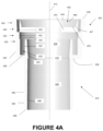
- the mount connector 402 deforms in response to the increased force caused by contact between the outer surface the annular locking protrusion 274a and the contact surface 456 of the interlocking ramps 452 caused by the decrease in radial dimension towards the trailing edge 453.
- the mount connector 402 Upon being fully inserted, the mount connector 402 returns substantially to its original shape and the locking edge 457 abuts the corresponding locking edge 276a of the tubular member 252a.
- the tube connector 404 has a generally cylindrical tubular member 482 formed around the longitudinal axis 412 with the channel 480 running therethrough.
- the channel 480 defines the inner surface 486, which tapers moving from the end 488 of the tube connector to the intersection 406.
- the inner surface 486 can have a generally constant radial dimension about the longitudinal axis 412 throughout the length of the tubular member 482.
- the radial dimension about the longitudinal axis 412 can increase when moving from the end 488 toward the intersection 406.
- the outer surface 482 can be of relatively constant radial dimension and can be configured to receive a mount connector 134 from the conduit tube 130.
- a generally hermetic seal can be formed, for example, by a friction fit, interference fit, or press fit.
- other types of coupling mechanisms such as a snap fit, a bayonet socket, threads, screws, tightening collars, retention collars, or other similar mechanisms can be used.
- the suction port 350a of the angled catheter mount 200a can comprise an opening 360a on the outer surface 370a of the suction port 350a.
- the opening 360a can be configured to allow insertion of a suction catheter 160 into the mount body 210a and into the flow channel 212a.
- the opening 360a is circular.
- the opening 360a may be of different shapes such as ovals, ellipses, and polygons. Circumscribing the opening 360a is engagement lip 362a that is configured to be received within an annular locking slot 520 of the valve 380a.
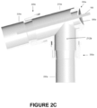
- a desired placement of the single opening 360a allows the suction catheter 160 to access both, as illustrated in Figure 2C , the interior of the conduit port 250a and possibly any attached tubing and, as illustrated in Figure 3D, the interior of the interface port 300a and possibly any attached tubing. Therefore, placement of the opening 360a advantageously allows direct access to both tubes without having to remove the catheter mount 200a from the system.
- Such a configuration reduces the amount of time necessary in maintaining the interior surfaces of a respiratory assistance system, such as those or the part thereof shown in Figures 1A-1C , since the catheter mount 200a need not be removed from the system for routine removal of condensate or the like.
- the opening 360a is opposite the interface port 300a and is centered on the interface axis 204a. In some embodiments, the opening 360a is parallel to a plane that is generally perpendicular to the interface axis 204a. As such, in the illustrated embodiment, the opening angle O a is equal to about 90°. In some embodiments, the opening angle O a can range from about 70° to about 160°. In some embodiments, the opening angle O a can range from about 75° to about 130°. In some embodiments, the opening angle O a can range from about 80° to about 100°.
- the opening angle O a may vary based on other design features, such as, but not limited to, the intersection angle I a , the offset distance D a from the conduit axis 202a, and the offset distance H a from the interface axis 204a, and the like as described in more detail below.
- an offset distance D a defined as the distance between the conduit axis 202a and an axis parallel to the conduit axis 202a running through the center of opening 360a.
- This offset distance D a can allow a conduit tube 160 sufficient space to access the conduit port 250a.
- the offset distance D a varies from about 0.1 cm to about 6.0 cm.
- the offset distance D a can vary from about 0.5 cm to about 3.0 cm.
- the offset distance D a can vary from about 0.5 cm to about 1 cm.
- the offset distance can be equal to about 0.7 cm.
- the offset distance D a can vary based on other design features, such as, but not limited to, the opening angle O a , the intersection angle I a , and the offset distance H a from the interface axis 204a, and the intended application.
- the offset distance D a may be about 0.7 cm for an adult catheter mount and about 0.36 cm for an infant catheter mount, for example.
- an offset distance H a defined as the distance between the interface axis 204a and an axis parallel to the interface axis 204a tangential to the uppermost part of the opening 360a.
- This offset distance H a can allow a conduit tube 160 sufficient space to access the conduit port 250a.
- the offset distance H a varies from about 0.2 cm to about 1.0 cm.
- the offset distance H a can vary from about 0.4 cm to about 0.8 cm.
- the offset distance H a can vary from about 0.5 cm to about 0.7 cm. In some embodiments, the offset distance can be equal to about 0.58 cm.
- the offset distance H a can vary based on other design features, such as, but not limited to, the opening angle O a , the intersection angle I a , and the offset distance D a from the conduit axis 202a, and the intended application.
- the offset distance H a may be 0.58 cm for an adult catheter mount and about 0.35 cm for an infant catheter mount, for example.
- intersection angle I a which in a preferred embodiment, is an acute angle.
- the intersection angle I a ranges from about 35° to about 90°.
- the intersection angle I a ranges from about 50° to about 85°.
- the intersection angle I a ranges from about 65° to about 80°.
- the intersection angle I a is about 75°.
- the offset distance H a can vary based on other design features, such as, but not limited to, the opening angle O a , the offset distance D a from the conduit axis 202a, and the offset distance H a from the interface axis 204a.
- the opening 360a may be raised vertically along the outer surface 370a, thereby increasing the offset distance H a as the opening angle O a is increased or decreased from 90°. In some embodiments, the offset distance H a and/or D a can be reduced as the intersection angle I a is decreased. Furthermore, the opening 360a is not limited to placement opposite the interface section 300a. In some embodiments, the opening 360a may be placed opposite the conduit section 204 with the same general placement principals being applicable.
- a valve 380a can be provided and received within the opening 360a of the suction port 350a.
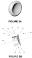
- Figs. 5A-5B are illustrations of an embodiment of the valve 380a which can be placed in the opening 360a.
- the design of the valves for other embodiments of the catheter mount, such as, but not limited to, the dual-valve catheter mount 200b and the switch catheter mount 200c, are similar to that of the valve 380a. As such, the description contained herein, can be applicable to the design of the valves for such other embodiments.
- the valve 380a can be manufactured from any suitable materials.
- the valve 380a can be manufactured from materials with sufficient elasticity such that the valve 330a can deform and conform to the shape of the opening 360a to provide a more effective seal.
- the valve 380a has an insertion member 500, an annular locking slot 520, an end cap 540, and inner channel 580.
- the valve 380a has a generally circular shape rotated about a central longitudinal axis 560.
- the insertion member 500 is configured to be received within the mount body 210a when fully assembled.
- the radial dimension of the outer surface 502 at the trailing end 504 of the insertion portion 500 about the longitudinal axis 560 is greater than the radial dimension of the opening 360a.
- the insertion portion 500 is preferably tapered at the leading end 506.
- the radial dimension of the outer surface 502 at the leading end 506 is equal to, or slightly less than, the diameter of opening 360a.
- the annular locking slot 520 can be configured to reduce the likelihood of undesired movement of the valve 380a when the valve has been attached to the mount body 210a.
- the dimensions of the annular locking slot 520 generally correspond to the dimensions of the engagement lip 362a.
- the radial dimension of the outer surface 522 of the locking slot 520 is generally equal to, or slightly greater than, the radial dimension of opening 360a.
- the radial dimension of the outer surface 522 can be sized slightly greater than the radial dimension of the opening 360a in order to provide a more airtight seal.
- the width of the locking slot 520 in the longitudinal direction may be equal to, or slightly less than, the width of the engagement lip 362a.
- the size of the annular locking slot 520 can be based upon the amount of sealing required, the elasticity of the material, and any concerns of ease of placement and replacement.
- the end cap 540 can be configured to control fluid communication through the inner channel 560.
- End cap 540 can be comprised of a generally flat surface 542 configured to abut the outer surface 370a of the suction port 350a when the valve is fully inserted within the mount body 210a.
- the end cap 540 can be tapered from the leading edge to the trailing edge. Other embodiments need not have the reduction in diameter and can be tapered or of constant diameter.
- the end cap has detent 546 configured to allow insertion of a suction catheter 160 or the like.
- detent may include a slit.
- the slit extends the center of the detent to allow a suction catheter 160 to be inserted into the valve 380a and into the inner channel 580 without the need to remove the valve 380a.
- the slit runs generally vertically such that the catheter can be moved along at least a portion of the slit in a generally vertical direction. When a suction catheter 160 is removed from the slit, the slit can return to its original shape and provide a generally hermetic seal.
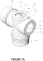
- FIGS 6-7 are illustrations of an embodiment of a dual-valve catheter mount 200b that is configured to allow a suction catheter 160 to access to both the conduit port 250b and the interface port 300b and possibly the corresponding tubes attached thereto due to the provision of two suction ports 350b, 351b.
- Dual-valve catheter mount 200b can be comprised of a conduit port 250b, an interface port 300b, and two suction ports 350b, 351b.
- the dual-valve catheter mount 200b has a mount body 210b configured to allow fluid communication between the conduit port 250b and the interface port 300b via flow channel 212b.
- the construction of the dual-valve catheter mount 200b is similar to that of the angled catheter mount 200a with the main exception that the interface angle I a is 90° and that the catheter mount 200b includes a dual-suction port 350b, 351b design.
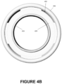
- reference should be made to the description of the angled catheter mount 200a for a description of the components contained in the dual-valve catheter mount 200b such as those for the conduit port 250b, the interface port 300b, the design of the reverse connectors 280b and 330b as shown in Figs. 4A-4B , and the design of the valves 380b and 381b as shown in Figs. 5A-5B .
- the dual-valve catheter mount 200b has a conduit suction port 351b directly opposite the conduit port 250b and an interface suction port 350b directly opposite the interface port 300b.
- Both the interface suction port 350b and the conduit suction port 351b have openings 360b, 361b respectively configured to permit insertion of a suction catheter 160 into the mount body 210b and into the flow channel 212b.
- the suction ports 350b, 351b and the associated openings 360b, 361b have generally circular shapes that are centered about the conduit axis 202b and the interface axis 204b respectively.
- both ports 350b, 351b and their respective openings 360b, 361b are generally the same.
- the size and shape of the ports may be dissimilar and may take on other shapes.
- ports and openings may also be elliptical, such as an oval, or polygonal, such as a square, rectangle, pentagon, hexagon or the like.
- the interface suction port 350b is extended beyond the outer wall of tubular member 252b of the conduit port 250b.
- the conduit suction port 351b is not extended beyond the outer wall of tubular member 302b of the interface port 300b.
- both of the suction ports 350b, 351b may be extended beyond the outer wall of the tubular members 302b, 252b in order to reduce the likelihood of interference or obstruction to flow within the fluid channel 212b of the mount body 210b.
- both suction ports, 351b may not be extended beyond the outer wall of the tubular members 302b, 252b.
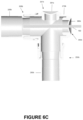
- openings 361b, 360b allows the suction catheter 160 to access both, as illustrated in Figure 6C , the interior of the conduit port 250b and possibly any attached tubing and, as illustrated in Figure 6D , the interior of the interface port 300b and possibly any attached tubing. Therefore, placement of the openings 360b, 361b advantageously allows direct access to both tubes without removal of the catheter mount 200b from the system. Such a configuration reduces the amount of time necessary in maintaining the interior surfaces of a respiratory assistance system because the catheter mount 200b need not be removed from the system in order to perform routine maintenance.
- the intersection of the conduit axis 202b and the interface axis 204b form an intersection angle I b .
- the intersection angle I b could be any angle from about 30° to about 150°.
- the intersection angle I b ranges from about 45° to about 135°.
- the intersection angle I b ranges from about 70° to about 110°.
- the intersection angle I b is about 90°.
- the intersection angle I b used for a particular embodiment of the dual-valve catheter mount 200b can be based on other design parameters such as, but not limited to, the offset angle O b and the placement of the two suction ports 350b, 351b.
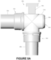
- FIGS 8-9 are illustrations of an embodiment of a switch catheter mount 200c that is configured to allow a suction catheter access to both the conduit port 250c and the interface port 300c and the corresponding tubes attached thereto due to the valve 380c and the switch 390c.
- the switch catheter mount 200c can comprise a conduit port 250c, an interface port 300c, and a suction port 350c.
- the switch catheter mount 200c has a mount body 210c configured to allow fluid communication between the conduit port 250c and the interface port 300c via the flow channel 212c.
- the construction of the switch catheter mount 200c can be similar to that of the dual-valve catheter mount 200b with the main exception that, rather than having a dual suction port design, the switch catheter mount 200c of the illustrated embodiment replaces one of the valves with a switch 390c.
- the description of the dual-valve catheter mount 200b for a description of the components contained in the switch catheter mount 200a such as those for the conduit port 250c, the interface port 300c, the design of the reverse connectors 280c and 330c as shown in Figs. 4A-4B , and the design of the valves 380c as shown in Figs. 5A-5B .
- the suction port 250c of the switch catheter mount 200c can be comprised of a suction port 350c directly opposite the interface port 300c and the switch 390c directly opposite the conduit port 250c.
- the suction port 350c can have an opening 360c configured to permit insertion of a suction catheter 160 into the mount body 210c and into the flow channel 212c.
- the suction port 350c and opening 360c have a generally circular shape formed about the interface axis 204c.
- circumscribing the opening 360c is an engagement lip 362c configured to be received within a locking slot 520 of the valve 380c being used.
- the size and shape of the port 350c and the opening 360c may vary.
- ports and openings may also be elliptical, such as an oval, or polygonal, such as a square, rectangle, pentagon, hexagon or the like.
- the switch 390c can be configured to redirect the suction catheter depending upon the positioning of the switch 390c.
- the switch 390c generally could be constructed of a material that would not substantially deform when contacting the suction catheter 160. Such materials could include, but are not limited to, plastics such as ABS, polycarbonate, polypropylene, HTPE, metals, composites, polymers, or other suitable materials.
- the switch 390c has a top portion 392c and a rod-shaped redirection portion 394c that is configured to redirect the suction catheter 160.
- the redirection portion 394c is configured to redirect the suction catheter 160
- the redirection portion 394c generally has a large cross-sectional area to facilitate contact with a suction catheter 160 that has been inserted into the mount body 210c. If the cross-sectional area is not sufficiently wide in a direction perpendicular to the cross-sectional plane shown in Figure 9 , a user of the device may find it difficult to redirect a suction catheter 160 into the conduit port 250c.
- the redirection portion 394c may have at least a portion with a rectangular cross-sectional area.
- additional design parameters include the length of the redirection portion 394c.
- the length of the redirection portion can be between about 0.5 cm and about 3.0 cm. In some embodiments, the length of the redirection portion can be between about 0.5 cm and about 2.0 cm. In some embodiments, the length of the redirection portion can be between about 0.5 cm and about 1.0 cm. Finally, in some embodiments, the length of the redirection portion is about 1.0 cm.
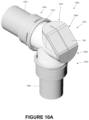
- Figures 10-12 show an exemplary embodiment of the invention and are illustrations of an embodiment of a wide-range valve catheter mount 200d that is configured to allow a suction catheter 160 to access both ports and possibly the corresponding tubes attached thereto due to the wide-range valve 600.
- the wide-range valve catheter mount 200d comprises a conduit port 250d, an interface port 300d, and a suction port 350d.
- the catheter mount 200d has a mount body 210d configured to allow fluid communication between the conduit port 250d, the interface port 300d, and the suction port 350d.
- the construction of the catheter mount 200d is similar to the preceding catheter mounts 200a, 200b, 200c with the main exception being that the wide-range valve catheter mount 200d uses a larger, wide-range valve 600 rather than the smaller valve 380 of the other catheter mounts.
- the description of the angled catheter mount 200a for a description of the components contained in the wide-range valve catheter mount 200d such as those for the conduit port 250d, the interface port 300d, and the design of the reverse connectors 280d and 330d as shown in Figs. 4A-4B .
- the suction port 350d of the wide range catheter mount 200d is comprised of a flat top surface 364d having a semi-circular shape, a flat chamfered surface 366d with a rectangular shape, a flat trailing surface 368d with a semicircular shape.
- a flat top surface 364d having a semi-circular shape
- a flat chamfered surface 366d with a rectangular shape having a flat trailing surface 368d with a semicircular shape.
- Other configurations are possible.
- an opening 360d can be defined through one or more of the surfaces 364d, 366d, 368d.
- the shape of the opening 360d can vary along the surfaces 364d, 366d, 368d.
- the opening 360d can have a generally semicircular shape and, along the chamfered surface 366d, the opening 360d can have a generally rectangular shape.
- the area of the opening 360d is approximately 1.2 times greater than the area of the conduit port 250c or the interface port 300d. In some embodiments, the area of the opening 360d can be greater than or less than the area of the ports 250c, 300c.
- the opening 360d can be centered on these surfaces such that an engagement lip 362d is formed and defined by the shape of the opening 360d.
- the engagement lip 362d can be configured to be received within an annular locking slot 640 of the wide-range valve 600.
- the location and configuration of the opening 360d allows the suction catheter 160 to access both, as illustrated in Figure 10C , the interior of the conduit port 250d and possibly any attached tubing and, as illustrated in Figure 10D , the interior of the interface port 300d and possibly any attached tubing.
- the illustrated configuration advantageously allows direct access to both tubes without having to remove the catheter mount 200d from the system. This reduces the amount of time spent in maintaining the interior surfaces of a respiratory assistance system because the catheter mount 200d facilitates this routine maintenance without requiring removal.
- the intersection of the conduit axis and the interface axis 204d form an intersection angle I d .
- the intersection angle I d could range from about 60° to about 120°. In some embodiments, the intersection angle I d ranges from about 70° to about 110°. In some embodiments, the intersection angle I d ranges from about 80° to about 100°. In some embodiments, such as that illustrated in Figs. 10-12 , the intersection angle I d is about 90°.
- the intersection angle I d used for a particular embodiment of the wide-range catheter mount 200d can be based on other design parameters such as, but not limited to, the size and placement of the opening 360d and the wide-range valve 600.
- the opening 360d can be of sufficient size such that both the conduit axis and the interface axis 204d pass through the aperture 360d along the top surface 364d and the trailing surface 368d respectively.
- the chamfered surface 366d is angled such that: (1) the first intermediate angle B 1 , defined as the angle of intersection between the conduit axis 202a and a line both coplanar with the conduit axis 202a and perpendicular to the chamfered surface 366d, is approximately equal to 45° and (2) the second intermediate angle B 2 , defined as the angle of intersection between the interface axis 204a and a line both coplanar with the interface axis 202a and perpendicular to the chamfered surface 366d, is approximately equal to 45°.
- both intermediate angles are generally equal.
- the intermediate angles may differ.
- the angles may differ.
- the wide-range valve catheter mount 200d may have openings 360d of different sizes, shapes and placements.
- the chamfered surface 366d may be omitted such that the two surfaces, 364d and 368d, are directly connected.
- the top surface 364d and the trailing surfaces 368d may be omitted such that only the chamfered surface 366d exists.
- the placement of the opening 360d may also be changed such that the opening 360d along the top and trailing surfaces 364d and 368d is placed further back such that the opening is not intersected by one or more of the conduit axis and interface axis 204d.
- the opening 360d may be moved forward such that the opening 360d along the chamfered surface 366d is intersected by either of the interface axis 204d, conduit axis or both.
- a wide-range valve 600 can be used in conjunction with the wide-range valve catheter mount 200d and received within the opening 360d of the suction port 350d.
- Figs. 12A-12C are illustrations of an embodiment of the wide-range valve 600 which can be used to provide a generally hermetic seal.
- the valve 600 can be manufactured from any suitable materials keeping in mind the desire to allow the valve to accommodate the suction catheter 160.
- the valve 600 is manufactured from materials with sufficient elasticity such that the valve 600 can deform and conform to the shape of the opening 360d to provide a more effective seal.
- the wide-range valve 600 has an insertion member 620, a locking slot 640, an end cap 660, and inner channel 680.
- the insertion member 620 is configured to be received within the mount body 210d when fully assembled.
- the shape of the insertion member 620 generally corresponds to the shape of the opening 360d being used for the wide-range catheter mount 200d.
- the insertion member 620 is sized such that, at least at the trailing end 622, the insertion member 900 has dimensions greater than those of the opening 360d.
- the shape of the insertion member 620 remains generally constant throughout its length from the leading edge 624 to the trailing edge 622.
- the insertion portion 320 in order to facilitate insertion of the insertion portion 620 into the aperture 360d due to the differences in size, can be tapered along the leading end 624.
- the size and shape of the leading end 624 is equal to, or slightly smaller than, the size and shape of the opening 360d in order to facilitate insertion into the catheter mount 200d.
- the locking slot 640 can be configured to reduce or eliminate the likelihood of movement of the wide-range valve 600 when attached to the mount body 210d.
- the dimensions of the annular locking slot 640 generally correspond to the dimensions of the engagement lip 362d.
- the annular locking slot 640 can be sized and shaped to be slightly larger than the opening 360d in order to provide a more generally hermetic seal.
- the size and shape can be slightly greater depending on the elastic properties of the wide-range valve 600. When fully inserted, the sections of the wide-range valve 600 in contact with the mount body 210d surfaces are compressed and form a more advantageous seal.
- the dimensions chosen are based on the type of material being used, the amount of sealing required, and considerations of difficulty of insertion and removal of the valve.
- the end cap 660 is configured to control fluid communication to the inner channel 680.
- end cap 660 is comprised of a flat surface 664 configured to abut the top surface 364d, the chamfered surface 366d, and the trailing surface 368d, of the mount body 210d when the valve 600 is fully inserted within the mount body 210d.
- the size and shape of the end cap 660 generally corresponds to the size and shape of surfaces 364d, 366d, 368d.
- the end cap 660 has slit 670 running through the end cap 660 and into the inner channel 680.
- a single slit 670 runs through a central section of the top portion 674, an entire central section of the chamfered portion 676, and a central section of the trailing portion 678 of the valve.
- the slit 670 allow a suction catheter 160 to be inserted into the valve 600 and into the inner channel 680 without removal of the valve 600.
- the slit can return to its original shape and provide a generally hermetic seal.
- the slit runs solely through the chamfered portion 676.
- multiple slits may be used.
- a first slit can exist along a central part of the top portion 674 and a second slit can exist along a central part of the trailing portion 678.
- Figure 13 illustrates an embodiment of a ball-joint catheter mount 200e with a conduit port 250e and an interface port 300e.
- the conduit portion 250e and the interface port 300e can rotate relative to each other to allow a suction catheter 160 to access to both connectors and possibly the corresponding tubes attached thereto.
- the ball-joint catheter mount 200e also has a suction port 350e opposite the interface port 300e.
- the ball-joint catheter mount 200e has a mount body 210e configured to allow fluid communication between the conduit port 250e, the interface port 300e, and the suction port 350e through an interior flow channel 212e.
- the conduit port 250e is attached to a ball-joint assembly 700 allowing the conduit port 250e to be rotated.
- the suction port 350a is oriented opposite the conduit port 250a with the interface port 300e attached to the ball-joint assembly 700.
- the construction of the ball-joint catheter mount 200e is similar to that of the above-described catheter mounts such as the angled catheter mount 200a with the main exception that, rather than being fixed, the ball-joint catheter mount 200e can be rotated thereby changing the interface axis 204e and resulting in a modifiable intersection angle I e .
- the dual-valve catheter mount 200b for a description of the components contained in the switch catheter mount 200a such as those for the conduit port 250c, the interface port 300c, the design of the reverse connectors 280c and 330c as shown in Figs. 4A-4B , and the design of the valves 380c as shown in Figs. 5A-5B .
- ball-joint catheter mount 200e can have an intersection angle I e of 90° or greater to facilitate placement near the interface 150.
- the ball-joint catheter mount can be rotated at the ball-joint assembly 700 to decrease the intersection angle I e and, similar to the angled catheter mount 200a, allow a suction catheter 160 to access both the conduit port 250e and the interface port 300e.
- the ball-joint assembly includes an arcuate inner surface such that the catheter can be better directed toward the conduit port 250e.
- the suction port 350e is non-movably positioned relative to an axis of the interface port 300e while being movably positioned relative to an axis of the conduit port 250e.
- a connector e.g., an intermediate suction tube connector
- the port and valve assembly can be angled to provide each of access to one or more components between the flow generators (e.g., ventilator) and the catheter mount.
- the connector it is possible to use the connector in combination with a standard catheter mount.
- a dual-valve catheter mount 200b may also have a narrow intersection angle I b akin to the angled catheter mount 200a.
- the ball-joint catheter mount 200e can also have a wide-range valve 600 of the wide-range valve catheter mount 200d rather than the smaller valve 380e. The remaining combinations and permutations are also included herein as embodiments.
Landscapes
- Health & Medical Sciences (AREA)
- Pulmonology (AREA)
- Heart & Thoracic Surgery (AREA)
- Engineering & Computer Science (AREA)
- Anesthesiology (AREA)
- Biomedical Technology (AREA)
- Hematology (AREA)
- Life Sciences & Earth Sciences (AREA)
- Animal Behavior & Ethology (AREA)
- General Health & Medical Sciences (AREA)
- Public Health (AREA)
- Veterinary Medicine (AREA)
- Emergency Medicine (AREA)
- Infusion, Injection, And Reservoir Apparatuses (AREA)
- External Artificial Organs (AREA)
Claims (14)
- Katheterstutzen (200d), der dazu konfiguriert ist, an einem Atemunterstützungssystem (100a, 100b) angebracht zu werden, wobei der Katheterstutzen (200d) Folgendes umfasst:eine Vielzahl von Ports (250d, 300d, 350d) in Fluidverbindung miteinander, wobei die Vielzahl von Ports (250d, 300d, 350d) Folgendes umfasst:einen Anschlussport (300d), der zum Koppeln mit einem Anschlusstubus (140) konfiguriert ist und eine Anschlussachse (204d) umfasst;einen Leitungsport (250d), der zum Koppeln mit einem Leitungstubus (130) konfiguriert ist und eine Leitungsachse umfasst; undeinen Absaugport (350d), der dazu konfiguriert ist, das Einführen eines Absaugkatheters (160) zu ermöglichen; undein Ventil (600), das mit dem Absaugport (350d) assoziiert ist und dazu konfiguriert ist, dem Absaugkatheter (160) durch den Absaugport (350d) direkten Zugang zu dem Anschlusstubus (140) zu ermöglichen, wobei die Anschlussachse (204d) des Anschlussports (300d) das Ventil (600) schneidet;dadurch gekennzeichnet, dass das Ventil (600) dazu konfiguriert ist, dem Absaugkatheter (160) direkten Zugang zu dem Leitungstubus (130) zu ermöglichen, und Leitungsachse das Ventil (600) schneidet.
- Katheterstutzen (200d) nach Anspruch 1, wobei das Ventil (600) eine flache abgeschrägte Oberfläche (676) umfasst, die einen in dem Ventil (600) gebildeten Zugangsschlitz (670) umgibt.
- Katheterstutzen (200d) nach Anspruch 1 oder 2, wobei das Ventil (600) eine flache obere Oberfläche (674) und/oder eine flache hintere Oberfläche (678) umfasst.
- Katheterstutzen (200d) nach Anspruch 2 oder Anspruch 3, wenn abhängig von Anspruch 2, wobei:
die flache abgeschrägte Oberfläche (676) eine rechteckige Form aufweist; die flache obere Oberfläche (674) im Wesentlichen halbkreisförmig ist; und/oder die flache hintere Oberfläche (678) im Wesentlichen halbkreisförmig ist. - Katheterstutzen (200d) nach einem der vorangehenden Ansprüche, wobei das Ventil (600) verformbar ist und/oder dazu konfiguriert ist, eine im Wesentlichen hermetische Dichtung bereitzustellen.
- Katheterstutzen (200d) nach einem der vorangehenden Ansprüche, wobei ein Schnittwinkel (Id) zwischen der Leitungsachse und der Anschlussachse (204d) definiert ist, wobei der Schnittwinkel (Id) zwischen etwa 60 Grad und etwa 120 Grad beträgt.
- Katheterstutzen (200d) nach Anspruch 6, wobei der Schnittwinkel (Id) etwa 90 Grad beträgt.
- Katheterstutzen (200d) nach einem der vorangehenden Ansprüche, wobei:ein erster Zwischenwinkel (B1), der als ein Winkel zwischen der Leitungsachse und einer zu einer/der abgeschrägten Oberfläche (366d, 676) einer Ansaugportöffnung (360d) oder des Ventils (600) senkrechten Linie definiert ist, ungefähr gleich 45 Grad ist; und/oderein zweiter Zwischenwinkel (B2), der als ein Winkel zwischen der Anschlussachse (204d) und der zu der abgeschrägten Oberfläche (366d, 676) der Ansaugportöffnung (360d) oder des Ventils (600) senkrechten Linie definiert ist, ungefähr gleich 45 Grad ist.
- Katheterstutzen (200d) nach einem der vorangehenden Ansprüche, wobei:der Absaugport (350d) eine/die Ansaugportöffnung (360d) umfasst;das Ventil (600) einen/den Zugangsschlitz (670) umfasst; unddie Absaugportöffnung (360d) und/oder der Zugangsschlitz (670) des Ventils (600) die Anschlussachse (204d) und die Leitungsachse überlagern.
- Katheterstutzen (200d) nach einem der vorangehenden Ansprüche, wobei:
das Ventil (600) dazu konfiguriert ist, zu ermöglichen, dass der Absaugkatheter (160) eingeführt wird und sich selektiv entlang der Anschlussachse (204d) oder der Leitungsachse erstreckt. - Katheterstutzen (200d) nach einem der vorangehenden Ansprüche, umfassend einen/den Zugangsschlitz (670), der dazu konfiguriert ist, zu ermöglichen, dass der Absaugkatheter (160) durch den Schlitz (670) eingeführt wird, um Zugang zu dem Anschlussport (300d) und dem Leitungsport (250d) zu erhalten, wobei der Schlitz (670) dazu konfiguriert ist, in eine ursprüngliche Form zurückzukehren, wenn der Absaugkatheter (160) aus dem Schlitz (670) entfernt wird.
- Katheterstutzen (200d) nach einem der vorangehenden Ansprüche, wobei das Ventil (600) eine ringförmige Arretiernut (640) umfasst, wobei die Arretiernut (640) eine Eingriffslippe (362d) umfasst, die dazu konfiguriert ist, in der ringförmigen Arretiernut (640) des Ventils (600) aufgenommen zu werden.
- Katheterstutzen (200d) nach Anspruch 12, wobei der Absaugport (350d) eine/die Öffnung (360d) umfasst, wobei die ringförmige Arretiernut (640) etwa größer als die Öffnung (360d) bemessen und geformt ist.
- Atemunterstützungssystem (100a, 100b), umfassend:einen Atemkreislauf (120), umfassend einen Inspirationstubus (122) und einen Exspirationstubus (124); undden Katheterstutzen (200d) nach einem der vorangehenden Ansprüche.
Applications Claiming Priority (5)
| Application Number | Priority Date | Filing Date | Title |
|---|---|---|---|
| US201361785798P | 2013-03-14 | 2013-03-14 | |
| EP14765620.1A EP2968808B1 (de) | 2013-03-14 | 2014-03-14 | Katheterstutzen mit saugport |
| EP19172997.9A EP3603715B1 (de) | 2013-03-14 | 2014-03-14 | Katheterstutzen mit saugport |
| PCT/NZ2014/000037 WO2014142678A1 (en) | 2013-03-14 | 2014-03-14 | Catheter mount with suction port |
| EP21153311.2A EP3827863B1 (de) | 2013-03-14 | 2014-03-14 | Katheterstutzen mit saugport |
Related Parent Applications (4)
| Application Number | Title | Priority Date | Filing Date |
|---|---|---|---|
| EP21153311.2A Division EP3827863B1 (de) | 2013-03-14 | 2014-03-14 | Katheterstutzen mit saugport |
| EP21153311.2A Division-Into EP3827863B1 (de) | 2013-03-14 | 2014-03-14 | Katheterstutzen mit saugport |
| EP14765620.1A Division EP2968808B1 (de) | 2013-03-14 | 2014-03-14 | Katheterstutzen mit saugport |
| EP19172997.9A Division EP3603715B1 (de) | 2013-03-14 | 2014-03-14 | Katheterstutzen mit saugport |
Publications (2)
| Publication Number | Publication Date |
|---|---|
| EP4223339A1 EP4223339A1 (de) | 2023-08-09 |
| EP4223339B1 true EP4223339B1 (de) | 2025-01-29 |
Family
ID=51537164
Family Applications (4)
| Application Number | Title | Priority Date | Filing Date |
|---|---|---|---|
| EP23165160.5A Active EP4223339B1 (de) | 2013-03-14 | 2014-03-14 | Katheterstutzen mit saugport |
| EP14765620.1A Active EP2968808B1 (de) | 2013-03-14 | 2014-03-14 | Katheterstutzen mit saugport |
| EP19172997.9A Active EP3603715B1 (de) | 2013-03-14 | 2014-03-14 | Katheterstutzen mit saugport |
| EP21153311.2A Active EP3827863B1 (de) | 2013-03-14 | 2014-03-14 | Katheterstutzen mit saugport |
Family Applications After (3)
| Application Number | Title | Priority Date | Filing Date |
|---|---|---|---|
| EP14765620.1A Active EP2968808B1 (de) | 2013-03-14 | 2014-03-14 | Katheterstutzen mit saugport |
| EP19172997.9A Active EP3603715B1 (de) | 2013-03-14 | 2014-03-14 | Katheterstutzen mit saugport |
| EP21153311.2A Active EP3827863B1 (de) | 2013-03-14 | 2014-03-14 | Katheterstutzen mit saugport |
Country Status (3)
| Country | Link |
|---|---|
| US (4) | US10413687B2 (de) |
| EP (4) | EP4223339B1 (de) |
| WO (1) | WO2014142678A1 (de) |
Families Citing this family (14)
| Publication number | Priority date | Publication date | Assignee | Title |
|---|---|---|---|---|
| AU2005228826B2 (en) | 2004-03-31 | 2008-05-08 | Fisher & Paykel Healthcare Limited | A patient ventilating and aspirating system |
| EP4223339B1 (de) | 2013-03-14 | 2025-01-29 | Fisher & Paykel Healthcare Limited | Katheterstutzen mit saugport |
| EP3177353B1 (de) | 2014-08-08 | 2018-05-23 | Vyaire Medical Consumables LLC | Luftwegadapter und ansaugkathetersysteme |
| US20160243329A1 (en) * | 2015-02-18 | 2016-08-25 | Alexander C. Chen | High flow ventilation system for endoscopy procedures |
| HK1250925A1 (zh) * | 2015-04-06 | 2019-01-18 | Janssen Pharmaceutica, N.V. | 包含依鲁替尼的组合物 |
| GB2542479B (en) * | 2015-07-24 | 2020-04-15 | Fisher & Paykel Healthcare Ltd | Tracheostomy guard |
| KR101729027B1 (ko) | 2016-09-23 | 2017-04-21 | (주)엘메카 | 착탈식 카테터 구조체 |
| US10864338B2 (en) * | 2017-05-19 | 2020-12-15 | Austere Medical Group, Llc | Rescue breathing apparatus |
| WO2019058199A1 (en) * | 2017-09-19 | 2019-03-28 | FISH, Frank | NEBULIZER ORIENTATION APPARATUS |
| DE102018113154A1 (de) * | 2018-06-01 | 2019-12-05 | Ventinova Technologies B.V. | Endotrachealtubusadapter |
| US12090297B2 (en) | 2019-10-01 | 2024-09-17 | Instrumentation Industries, Inc. | Adaptors for removal of debris and fluids from ventilator circuits |
| DE102020000503B4 (de) * | 2020-01-28 | 2023-02-02 | Drägerwerk AG & Co. KGaA | Gekrümmte Verbindungseinheit zum Verbinden eines Patienten mit einem Beatmungsgerät |
| WO2022251735A1 (en) * | 2021-05-28 | 2022-12-01 | Morejon Orlando V | Adjustable valve assembly for medical tubing |
| CN120916807A (zh) * | 2023-02-24 | 2025-11-07 | 费雪派克医疗保健有限公司 | 用于连接呼吸管的适配器 |
Family Cites Families (106)
| Publication number | Priority date | Publication date | Assignee | Title |
|---|---|---|---|---|
| US4211229A (en) | 1977-12-01 | 1980-07-08 | Richard Wolf Medical Instruments Corp. | Laser endoscope |
| US4351328A (en) | 1980-03-27 | 1982-09-28 | Sontek Industries, Inc. | Simultaneous respiration and endotracheal suctioning of a critically ill patient |
| US4475548A (en) | 1982-06-01 | 1984-10-09 | Rudolph Muto | Fitting for endotracheal tube apparatus and method of making the fitting |
| USD282772S (en) | 1982-11-29 | 1986-02-25 | Fleury William A | Aspirator fitting |
| US4531328A (en) | 1983-02-07 | 1985-07-30 | Jewett Bryce D | Tooth rest for cutter grinder |
| US4569344A (en) | 1984-07-23 | 1986-02-11 | Ballard Medical Products | Aspirating/ventilating apparatus and method |
| US4836199A (en) | 1984-07-23 | 1989-06-06 | Ballard Medical Products | Aspirating/ventilating apparatus and method |
| DE3538033A1 (de) | 1985-10-25 | 1987-04-30 | Lang Volker | Vorrichtung zum anschliessen von patienten an respiratoren mit einfuehrventil fuer absaugsonden und kondenswasser-eliminationsautomatik |
| US5135489A (en) | 1988-01-25 | 1992-08-04 | Baxter International Inc. | Pre-slit injection site and tapered cannula |
| IE66526B1 (en) | 1989-03-17 | 1996-01-24 | Baxter Int | A pre-slit injection site usable with a blunt cannula |
| US5060646A (de) * | 1990-09-10 | 1991-10-29 | ||
| US5259376A (en) * | 1990-09-26 | 1993-11-09 | Bales Joseph H | Tracheostomy tube assembly |
| US5255676A (en) | 1991-11-08 | 1993-10-26 | Russo Ronald D | Safety sealed tracheal suction system |
| DK0988871T3 (da) | 1991-12-18 | 2004-05-24 | Icu Medical Inc | Fremgangsmåde til overføring af fluid |
| DE69329711T2 (de) | 1992-04-24 | 2001-08-02 | Sherwood Services Ag, Schaffhausen | Atmungsunterstützungssystem |
| US5309902A (en) | 1992-10-19 | 1994-05-10 | Sherwood Medical Company | Respiratory support system and suction catheter device therefor |
| US5333606A (en) | 1992-04-24 | 1994-08-02 | Sherwood Medical Company | Method for using a respirator accessory access port and adaptor therefore |
| US5313934A (en) | 1992-09-10 | 1994-05-24 | Deumed Group Inc. | Lens cleaning means for invasive viewing medical instruments |
| GB2270845B (en) | 1992-09-24 | 1996-07-10 | Smiths Ind Med Syst Inc | Suction catheter assemblies |
| US5329921A (en) | 1993-03-01 | 1994-07-19 | Spiro Socaris | Endotracheal tube |
| US5513628A (en) | 1993-07-14 | 1996-05-07 | Sorenson Critical Care, Inc. | Apparatus and method for ventilating and aspirating |
| EP0672430A3 (de) | 1994-03-15 | 1995-12-27 | Fisher & Paykel | Befeuchtenleitung. |
| US5549554A (en) | 1994-04-01 | 1996-08-27 | Advanced Cardiovascular Systems, Inc. | Catheters having separable reusable components |
| US5694922A (en) * | 1994-05-18 | 1997-12-09 | Ballard Medical Products | Swivel tube connections with hermetic seals |
| DE69430145T2 (de) | 1994-09-19 | 2002-10-31 | Sorenson Medical, Inc. | Gerät zum ventilieren und aspirieren |
| US5501214A (en) | 1994-09-26 | 1996-03-26 | Respironics, Inc. | Non-rebreathing valve and valve element therefor |
| US5711294A (en) * | 1994-12-21 | 1998-01-27 | Sherwood Medical Company | Ventilator manifold having cleaning ports and method of use thereof |
| WO1996026757A1 (en) * | 1995-02-28 | 1996-09-06 | Ballard Medical Products | Access control respiratory devices and methods |
| US5598840A (en) | 1995-03-17 | 1997-02-04 | Sorenson Critical Care, Inc. | Apparatus and method for ventilation and aspiration |
| IL114960A0 (en) | 1995-03-20 | 1995-12-08 | Medimop Medical Projects Ltd | Flow control device |
| EP0827416A4 (de) | 1995-03-28 | 1999-06-09 | Ballard Med Prod | Katheterhülle mit anti-kontaminationsbarrierren in form von filter bzw. verschluss |
| US5775325A (en) | 1995-05-11 | 1998-07-07 | Russo; Ronald D. | Two part closed tracheal suction system |
| US6245048B1 (en) | 1996-12-16 | 2001-06-12 | Icu Medical, Inc. | Medical valve with positive flow characteristics |
| US6702789B1 (en) | 1997-03-11 | 2004-03-09 | Alcove Medical, Inc. | Catheter having insertion control mechanism and anti-bunching mechanism |
| US6086529A (en) | 1997-05-13 | 2000-07-11 | Wisconsin Medical, Inc. | Bronchoscopic manifold with compressible diaphragmatic valve for simultaneous airway instrumentation |
| US6109259A (en) | 1997-12-10 | 2000-08-29 | Spirit Medical Systems, Inc. | Gas supplying and substance suctioning relative to a patients trachea |
| US6068609A (en) | 1998-05-19 | 2000-05-30 | Douglas E. Ott | Method and apparatus for conditioning gas for medical procedures having humidity monitoring and recharge alert |
| BR9804529A (pt) * | 1998-10-23 | 2000-04-25 | Newmed Importadora Ltda | Dispositivo para realização de aspirador de secreções em pacientes entubados ou traquenostomizados e kit contendo um dispositivo para realização de aspiração de secreções em pacientes entubados ou tranqueostomizados. |
| US6269813B1 (en) | 1999-01-15 | 2001-08-07 | Respironics, Inc. | Tracheal gas insufflation bypass and phasic delivery system and method |
| US6287280B1 (en) | 1999-09-07 | 2001-09-11 | Merit Medical Systems, Inc. | Hemostasis valve apparatus with integral introducer |
| US6615835B1 (en) * | 1999-09-20 | 2003-09-09 | Ballard Medical Products | Flexible multiple port adaptor |
| DE60131150T2 (de) * | 2000-04-06 | 2008-08-14 | Unomedical A/S | Verteiler |
| US20010044600A1 (en) | 2000-05-17 | 2001-11-22 | Elkins John I. | Closed catheter suction system |
| USD453221S1 (en) | 2000-06-12 | 2002-01-29 | Elcam Plastic Cooperative Agricultural Association Ltd. | Luer-type connector |
| US6575944B1 (en) | 2000-06-19 | 2003-06-10 | Portex, Inc. | Adapter for localized treatment through a tracheal tube and method for use thereof |
| US6695817B1 (en) | 2000-07-11 | 2004-02-24 | Icu Medical, Inc. | Medical valve with positive flow characteristics |
| US6612304B1 (en) * | 2000-10-05 | 2003-09-02 | Kimberly-Clark Worldwide, Inc. | Respiratory care multiple access port assembly and adapter |
| US6895803B2 (en) | 2000-10-20 | 2005-05-24 | Fisher & Paykel Healthcare Limited | Humidity sensor |
| US6769430B1 (en) | 2000-10-31 | 2004-08-03 | Kimberly-Clark Worldwide, Inc. | Heat and moisture exchanger adaptor for closed suction catheter assembly and system containing the same |
| US6629530B2 (en) | 2000-12-22 | 2003-10-07 | Kimberly-Clark Worldwide, Inc. | Single-element sealing valve for a respiratory support system |
| US6923184B1 (en) | 2001-02-05 | 2005-08-02 | Ronald D. Russo | Suction system with high efficiency suction control valve |
| US7490604B2 (en) | 2002-03-15 | 2009-02-17 | C. R. Bard, Inc. | Endotracheal surfactant distribution system |
| US8353895B2 (en) | 2002-04-16 | 2013-01-15 | Ronald D Russo | Closed system irrigation connector for urinary catheters |
| DE10234811C1 (de) | 2002-07-31 | 2003-11-27 | Draeger Medical Ag | Atemgasanfeuchtersystem für einen Patienten |
| US20040181192A1 (en) | 2003-03-11 | 2004-09-16 | Cuppy Michael John | Vascular access device and method of using same |
| AU2004202274B2 (en) | 2003-05-30 | 2006-10-26 | Fisher & Paykel Healthcare Limited | Breathing Assistance Apparatus |
| US8118024B2 (en) | 2003-08-04 | 2012-02-21 | Carefusion 203, Inc. | Mechanical ventilation system utilizing bias valve |
| WO2005048982A2 (en) | 2003-11-17 | 2005-06-02 | Nektar Therapeutics | Efficient introduction of an aerosol into a ventilator circuit |
| AU2005228826B2 (en) | 2004-03-31 | 2008-05-08 | Fisher & Paykel Healthcare Limited | A patient ventilating and aspirating system |
| US20060025724A1 (en) | 2004-07-27 | 2006-02-02 | Globe Medical Tech, Inc. | Medical connector with valve |
| US7523967B2 (en) | 2004-12-13 | 2009-04-28 | Alcon, Inc. | Tubing fitting |
| US7931619B2 (en) | 2005-01-04 | 2011-04-26 | C. R. Bard, Inc. | Power injection catheters |
| US7665465B2 (en) | 2005-03-25 | 2010-02-23 | Ric Investments, Llc | Headgear assembly for a respiratory support system |
| US7568483B2 (en) | 2005-05-06 | 2009-08-04 | Ric Investments, Llc | Patient interface with respiratory gas measurement component |
| US7870857B2 (en) | 2005-05-23 | 2011-01-18 | Aeon Research And Technology, Inc. | Patient interface assemblies for use in ventilator systems to deliver medication to a patient |
| US20070088292A1 (en) | 2005-07-06 | 2007-04-19 | Fangrow Thomas F Jr | Medical connector with closeable male luer |
| AU2006272088A1 (en) * | 2005-07-18 | 2007-01-25 | Bayer Schering Pharma Aktiengesellschaft | Novel use of activators and stimulators of soluble guanylate cyclase for the prevention or treatment of renal disorders |
| US8287503B2 (en) | 2006-03-13 | 2012-10-16 | Applied Medical Resources Corporation | Balloon trocar |
| DE202006007397U1 (de) | 2006-05-08 | 2007-09-20 | GRÜNDLER GmbH | Beatmungsschlauch mit unterschiedlichen Heizzonen |
| GB0616687D0 (en) * | 2006-08-23 | 2006-10-04 | Smiths Group Plc | Fluid-flow apparatus and arrangements |
| AU2007308835A1 (en) | 2006-10-25 | 2008-05-02 | Icu Medical, Inc. | Medical connector |
| US8377040B2 (en) | 2006-11-06 | 2013-02-19 | Becton, Dickinson And Company | Extravascular system venting |
| DE102007003454B4 (de) | 2007-01-18 | 2009-05-28 | Schaller, Peter, Dr.-Ing.habil. | Beheizungssystem für einen Beatmungsschlauch |
| WO2008142359A1 (en) * | 2007-05-17 | 2008-11-27 | Ventaneb Limited | Resuscitation and breathing apparatus |
| US20090182309A1 (en) | 2008-01-11 | 2009-07-16 | Dartmouth-Hitchcock Clinic | Medical fluid coupling port with guide for reduction of contamination |
| WO2009136871A1 (en) * | 2008-05-06 | 2009-11-12 | National University Of Singapore | An improved cannula adaptor |
| AU2015264908B2 (en) | 2008-05-09 | 2017-06-29 | Pari Pharma Gmbh | Nebuliser for Ventilation Machines and a Ventilation Machine Comprising such a Nebuliser |
| US8777933B2 (en) * | 2008-10-10 | 2014-07-15 | Mergenet Medical, Inc. | Respiratory secretion retention device, system and method |
| US8591496B2 (en) | 2008-10-10 | 2013-11-26 | Mergenet Medical, Inc. | Respiratory secretion retention device, system and method |
| US8814838B2 (en) * | 2008-10-10 | 2014-08-26 | Mergenat Medical, Inc. | Respiratory secretion retention device, system and method |
| US8679090B2 (en) | 2008-12-19 | 2014-03-25 | Icu Medical, Inc. | Medical connector with closeable luer connector |
| US8444627B2 (en) * | 2008-12-31 | 2013-05-21 | Kimberly-Clark Worldwide, Inc. | Respiratory manifold with bridge |
| US10532177B2 (en) | 2009-12-22 | 2020-01-14 | Fisher & Paykel Healthcare Limited | Components for medical circuits |
| US20120022331A1 (en) | 2010-01-11 | 2012-01-26 | Minimally Invasive Devices, Llc | Systems and Methods for Optimizing and Maintaining Visualization of a Surgical Field During the Use of Surgical Scopes |
| HUE046268T2 (hu) | 2010-10-22 | 2020-02-28 | Hewlett Packard Development Co | Folyadékpatron |
| WO2012080941A1 (en) | 2010-12-17 | 2012-06-21 | Koninklijke Philips Electronics N.V. | System and method for administering humidified gas to a ventilated patient |
| DE102011055439A1 (de) | 2011-11-17 | 2013-05-23 | Hamilton Bonaduz Ag | Schlauch für ein Beatmungssystem |
| US20130269686A1 (en) | 2012-01-25 | 2013-10-17 | Thomas Jefferson University Hospitals, Inc. | Nebulizer assemblies |
| US9597470B2 (en) * | 2012-02-06 | 2017-03-21 | Cook Medical Technologies Llc | Manifold having rotatable ports |
| GB2541301B (en) | 2012-03-15 | 2017-07-12 | Fisher & Paykel Healthcare Ltd | Respiratory gas humidification system |
| US9993608B2 (en) | 2012-05-02 | 2018-06-12 | Fisher & Paykel Healthcare Limited | Respiratory humidifier communication systems and methods |
| JP6412879B2 (ja) | 2012-12-04 | 2018-10-24 | フィッシャー アンド ペイケル ヘルスケア リミテッド | 医療用チューブおよびその製造方法 |
| EP4223339B1 (de) | 2013-03-14 | 2025-01-29 | Fisher & Paykel Healthcare Limited | Katheterstutzen mit saugport |
| US20150087911A1 (en) | 2013-09-26 | 2015-03-26 | Gyrus Acmi, Inc. D.B.A Olympus Surgical Technologies America | Endoscope sheath deflection devices |
| US10814091B2 (en) | 2013-10-24 | 2020-10-27 | Fisher & Paykel Healthcare Limited | System for delivery of respiratory gases |
| JP6302740B2 (ja) | 2013-12-12 | 2018-03-28 | オリンパス株式会社 | 内視鏡用耐熱シースおよび内視鏡用耐熱シースを備えた内視鏡システム |
| CN111265754B (zh) | 2014-03-17 | 2023-06-06 | 费雪派克医疗保健有限公司 | 用于呼吸系统的医用管 |
| US20170280988A1 (en) | 2014-04-02 | 2017-10-05 | Visionscope Technologies Llc | Devices and methods for minimally invasive surgery |
| US9427541B2 (en) | 2014-04-30 | 2016-08-30 | Vitaltec Corporation | Switchable adapter for a suction tube |
| EP3177353B1 (de) | 2014-08-08 | 2018-05-23 | Vyaire Medical Consumables LLC | Luftwegadapter und ansaugkathetersysteme |
| CN107257648B (zh) | 2015-02-27 | 2020-04-03 | 柯惠有限合伙公司 | 具有零度视场角的倾斜尖端内窥镜 |
| CN112891694B (zh) | 2015-03-31 | 2026-03-17 | 费雪派克医疗保健有限公司 | 用于在呼吸支持系统中使用的设备 |
| EP3463536B1 (de) | 2016-06-07 | 2023-05-10 | Fisher & Paykel Healthcare Limited | Beatmungskreislaufkomponenten für atemvorrichtung |
| EP3525862B8 (de) | 2016-10-11 | 2023-08-16 | Fisher & Paykel Healthcare Limited | Verfahren zur erkennung von fehlern bei den anschlüssen in einem befeuchtungssystem |
| WO2018217105A1 (en) | 2017-05-26 | 2018-11-29 | Fisher And Paykel Healthcare Limited | Neonatal flexible and hybrid medical tubes |
| US20230014759A1 (en) | 2019-12-26 | 2023-01-19 | Fisher & Paykel Healthcare Limited | A respiratory therapy system, incubator, and medical breathing gas delivery conduit therefor |
-
2014
- 2014-03-14 EP EP23165160.5A patent/EP4223339B1/de active Active
- 2014-03-14 EP EP14765620.1A patent/EP2968808B1/de active Active
- 2014-03-14 WO PCT/NZ2014/000037 patent/WO2014142678A1/en not_active Ceased
- 2014-03-14 EP EP19172997.9A patent/EP3603715B1/de active Active
- 2014-03-14 US US14/776,459 patent/US10413687B2/en active Active
- 2014-03-14 EP EP21153311.2A patent/EP3827863B1/de active Active
-
2019
- 2019-08-06 US US16/532,875 patent/US10898667B2/en active Active
-
2020
- 2020-12-18 US US17/126,665 patent/US11701485B2/en active Active
-
2023
- 2023-05-19 US US18/320,887 patent/US12194238B2/en active Active
Also Published As
| Publication number | Publication date |
|---|---|
| EP2968808B1 (de) | 2019-06-05 |
| EP3827863A1 (de) | 2021-06-02 |
| US12194238B2 (en) | 2025-01-14 |
| US10413687B2 (en) | 2019-09-17 |
| EP2968808A4 (de) | 2016-09-28 |
| US20200069899A1 (en) | 2020-03-05 |
| WO2014142678A1 (en) | 2014-09-18 |
| EP4223339A1 (de) | 2023-08-09 |
| US20160022942A1 (en) | 2016-01-28 |
| EP3827863B1 (de) | 2023-06-07 |
| EP2968808A1 (de) | 2016-01-20 |
| US20230405252A1 (en) | 2023-12-21 |
| EP3603715B1 (de) | 2021-03-03 |
| EP3603715A1 (de) | 2020-02-05 |
| US11701485B2 (en) | 2023-07-18 |
| US10898667B2 (en) | 2021-01-26 |
| US20210170126A1 (en) | 2021-06-10 |
Similar Documents
| Publication | Publication Date | Title |
|---|---|---|
| EP4223339B1 (de) | Katheterstutzen mit saugport | |
| EP1551486B1 (de) | Atemwegsadapter mit geringem totraum | |
| US11040160B2 (en) | Compressible connector for an inner cannula | |
| US9211398B2 (en) | Connector system for an apparatus that delivers breathable gas to a patient | |
| US11571540B2 (en) | Respiratory valve apparatus and related method | |
| US9265906B2 (en) | Compressible cannula connector with release grip | |
| US9907921B2 (en) | Tracheostomy tube with inner cannula | |
| US20110265798A1 (en) | Medical device tube having spaced lumens and an associated ported adapter | |
| US11504493B2 (en) | Curved connection unit for connecting a patient to a medical device | |
| EP2613831B1 (de) | Ncpap zur atemaufwandreduzierung | |
| EP3871724B1 (de) | Auslassanschluss für eine positive exspiratorische therapievorrichtung |
Legal Events
| Date | Code | Title | Description |
|---|---|---|---|
| PUAI | Public reference made under article 153(3) epc to a published international application that has entered the european phase |
Free format text: ORIGINAL CODE: 0009012 |
|
| STAA | Information on the status of an ep patent application or granted ep patent |
Free format text: STATUS: THE APPLICATION HAS BEEN PUBLISHED |
|
| AC | Divisional application: reference to earlier application |
Ref document number: 2968808 Country of ref document: EP Kind code of ref document: P Ref document number: 3603715 Country of ref document: EP Kind code of ref document: P Ref document number: 3827863 Country of ref document: EP Kind code of ref document: P |
|
| AK | Designated contracting states |
Kind code of ref document: A1 Designated state(s): AL AT BE BG CH CY CZ DE DK EE ES FI FR GB GR HR HU IE IS IT LI LT LU LV MC MK MT NL NO PL PT RO RS SE SI SK SM TR |
|
| STAA | Information on the status of an ep patent application or granted ep patent |
Free format text: STATUS: REQUEST FOR EXAMINATION WAS MADE |
|
| 17P | Request for examination filed |
Effective date: 20231215 |
|
| RBV | Designated contracting states (corrected) |
Designated state(s): AL AT BE BG CH CY CZ DE DK EE ES FI FR GB GR HR HU IE IS IT LI LT LU LV MC MK MT NL NO PL PT RO RS SE SI SK SM TR |
|
| GRAP | Despatch of communication of intention to grant a patent |
Free format text: ORIGINAL CODE: EPIDOSNIGR1 |
|
| STAA | Information on the status of an ep patent application or granted ep patent |
Free format text: STATUS: GRANT OF PATENT IS INTENDED |
|
| INTG | Intention to grant announced |
Effective date: 20240909 |
|
| GRAS | Grant fee paid |
Free format text: ORIGINAL CODE: EPIDOSNIGR3 |
|
| GRAA | (expected) grant |
Free format text: ORIGINAL CODE: 0009210 |
|
| STAA | Information on the status of an ep patent application or granted ep patent |
Free format text: STATUS: THE PATENT HAS BEEN GRANTED |
|
| P01 | Opt-out of the competence of the unified patent court (upc) registered |
Free format text: CASE NUMBER: APP_66936/2024 Effective date: 20241218 |
|
| AC | Divisional application: reference to earlier application |
Ref document number: 2968808 Country of ref document: EP Kind code of ref document: P Ref document number: 3603715 Country of ref document: EP Kind code of ref document: P Ref document number: 3827863 Country of ref document: EP Kind code of ref document: P |
|
| AK | Designated contracting states |
Kind code of ref document: B1 Designated state(s): AL AT BE BG CH CY CZ DE DK EE ES FI FR GB GR HR HU IE IS IT LI LT LU LV MC MK MT NL NO PL PT RO RS SE SI SK SM TR |
|
| REG | Reference to a national code |
Ref country code: GB Ref legal event code: FG4D |
|
| REG | Reference to a national code |
Ref country code: CH Ref legal event code: EP |
|
| REG | Reference to a national code |
Ref country code: DE Ref legal event code: R096 Ref document number: 602014091517 Country of ref document: DE |
|
| REG | Reference to a national code |
Ref country code: IE Ref legal event code: FG4D |
|
| REG | Reference to a national code |
Ref country code: NL Ref legal event code: MP Effective date: 20250129 |
|
| PG25 | Lapsed in a contracting state [announced via postgrant information from national office to epo] |
Ref country code: NL Free format text: LAPSE BECAUSE OF FAILURE TO SUBMIT A TRANSLATION OF THE DESCRIPTION OR TO PAY THE FEE WITHIN THE PRESCRIBED TIME-LIMIT Effective date: 20250129 |
|
| PG25 | Lapsed in a contracting state [announced via postgrant information from national office to epo] |
Ref country code: RS Free format text: LAPSE BECAUSE OF FAILURE TO SUBMIT A TRANSLATION OF THE DESCRIPTION OR TO PAY THE FEE WITHIN THE PRESCRIBED TIME-LIMIT Effective date: 20250429 |
|
| PG25 | Lapsed in a contracting state [announced via postgrant information from national office to epo] |
Ref country code: FI Free format text: LAPSE BECAUSE OF FAILURE TO SUBMIT A TRANSLATION OF THE DESCRIPTION OR TO PAY THE FEE WITHIN THE PRESCRIBED TIME-LIMIT Effective date: 20250129 |
|
| PG25 | Lapsed in a contracting state [announced via postgrant information from national office to epo] |
Ref country code: PL Free format text: LAPSE BECAUSE OF FAILURE TO SUBMIT A TRANSLATION OF THE DESCRIPTION OR TO PAY THE FEE WITHIN THE PRESCRIBED TIME-LIMIT Effective date: 20250129 |
|
| PG25 | Lapsed in a contracting state [announced via postgrant information from national office to epo] |
Ref country code: ES Free format text: LAPSE BECAUSE OF FAILURE TO SUBMIT A TRANSLATION OF THE DESCRIPTION OR TO PAY THE FEE WITHIN THE PRESCRIBED TIME-LIMIT Effective date: 20250129 |
|
| REG | Reference to a national code |
Ref country code: LT Ref legal event code: MG9D |
|
| PG25 | Lapsed in a contracting state [announced via postgrant information from national office to epo] |
Ref country code: IS Free format text: LAPSE BECAUSE OF FAILURE TO SUBMIT A TRANSLATION OF THE DESCRIPTION OR TO PAY THE FEE WITHIN THE PRESCRIBED TIME-LIMIT Effective date: 20250529 Ref country code: NO Free format text: LAPSE BECAUSE OF FAILURE TO SUBMIT A TRANSLATION OF THE DESCRIPTION OR TO PAY THE FEE WITHIN THE PRESCRIBED TIME-LIMIT Effective date: 20250429 |
|
| REG | Reference to a national code |
Ref country code: AT Ref legal event code: MK05 Ref document number: 1762843 Country of ref document: AT Kind code of ref document: T Effective date: 20250129 |
|
| PG25 | Lapsed in a contracting state [announced via postgrant information from national office to epo] |
Ref country code: HR Free format text: LAPSE BECAUSE OF FAILURE TO SUBMIT A TRANSLATION OF THE DESCRIPTION OR TO PAY THE FEE WITHIN THE PRESCRIBED TIME-LIMIT Effective date: 20250129 |
|
| PG25 | Lapsed in a contracting state [announced via postgrant information from national office to epo] |
Ref country code: LV Free format text: LAPSE BECAUSE OF FAILURE TO SUBMIT A TRANSLATION OF THE DESCRIPTION OR TO PAY THE FEE WITHIN THE PRESCRIBED TIME-LIMIT Effective date: 20250129 Ref country code: PT Free format text: LAPSE BECAUSE OF FAILURE TO SUBMIT A TRANSLATION OF THE DESCRIPTION OR TO PAY THE FEE WITHIN THE PRESCRIBED TIME-LIMIT Effective date: 20250529 |
|
| PG25 | Lapsed in a contracting state [announced via postgrant information from national office to epo] |
Ref country code: BG Free format text: LAPSE BECAUSE OF FAILURE TO SUBMIT A TRANSLATION OF THE DESCRIPTION OR TO PAY THE FEE WITHIN THE PRESCRIBED TIME-LIMIT Effective date: 20250129 Ref country code: GR Free format text: LAPSE BECAUSE OF FAILURE TO SUBMIT A TRANSLATION OF THE DESCRIPTION OR TO PAY THE FEE WITHIN THE PRESCRIBED TIME-LIMIT Effective date: 20250430 |
|
| PG25 | Lapsed in a contracting state [announced via postgrant information from national office to epo] |
Ref country code: AT Free format text: LAPSE BECAUSE OF FAILURE TO SUBMIT A TRANSLATION OF THE DESCRIPTION OR TO PAY THE FEE WITHIN THE PRESCRIBED TIME-LIMIT Effective date: 20250129 |
|
| PG25 | Lapsed in a contracting state [announced via postgrant information from national office to epo] |
Ref country code: SE Free format text: LAPSE BECAUSE OF FAILURE TO SUBMIT A TRANSLATION OF THE DESCRIPTION OR TO PAY THE FEE WITHIN THE PRESCRIBED TIME-LIMIT Effective date: 20250129 |
|
| PG25 | Lapsed in a contracting state [announced via postgrant information from national office to epo] |
Ref country code: SM Free format text: LAPSE BECAUSE OF FAILURE TO SUBMIT A TRANSLATION OF THE DESCRIPTION OR TO PAY THE FEE WITHIN THE PRESCRIBED TIME-LIMIT Effective date: 20250129 |
|
| PG25 | Lapsed in a contracting state [announced via postgrant information from national office to epo] |
Ref country code: DK Free format text: LAPSE BECAUSE OF FAILURE TO SUBMIT A TRANSLATION OF THE DESCRIPTION OR TO PAY THE FEE WITHIN THE PRESCRIBED TIME-LIMIT Effective date: 20250129 |
|
| PG25 | Lapsed in a contracting state [announced via postgrant information from national office to epo] |
Ref country code: MC Free format text: LAPSE BECAUSE OF FAILURE TO SUBMIT A TRANSLATION OF THE DESCRIPTION OR TO PAY THE FEE WITHIN THE PRESCRIBED TIME-LIMIT Effective date: 20250129 |
|
| PG25 | Lapsed in a contracting state [announced via postgrant information from national office to epo] |
Ref country code: IT Free format text: LAPSE BECAUSE OF FAILURE TO SUBMIT A TRANSLATION OF THE DESCRIPTION OR TO PAY THE FEE WITHIN THE PRESCRIBED TIME-LIMIT Effective date: 20250129 |
|
| PG25 | Lapsed in a contracting state [announced via postgrant information from national office to epo] |
Ref country code: CZ Free format text: LAPSE BECAUSE OF FAILURE TO SUBMIT A TRANSLATION OF THE DESCRIPTION OR TO PAY THE FEE WITHIN THE PRESCRIBED TIME-LIMIT Effective date: 20250129 Ref country code: EE Free format text: LAPSE BECAUSE OF FAILURE TO SUBMIT A TRANSLATION OF THE DESCRIPTION OR TO PAY THE FEE WITHIN THE PRESCRIBED TIME-LIMIT Effective date: 20250129 |
|
| PG25 | Lapsed in a contracting state [announced via postgrant information from national office to epo] |
Ref country code: RO Free format text: LAPSE BECAUSE OF FAILURE TO SUBMIT A TRANSLATION OF THE DESCRIPTION OR TO PAY THE FEE WITHIN THE PRESCRIBED TIME-LIMIT Effective date: 20250129 |
|
| REG | Reference to a national code |
Ref country code: CH Ref legal event code: H13 Free format text: ST27 STATUS EVENT CODE: U-0-0-H10-H13 (AS PROVIDED BY THE NATIONAL OFFICE) Effective date: 20251024 |
|
| PG25 | Lapsed in a contracting state [announced via postgrant information from national office to epo] |
Ref country code: SK Free format text: LAPSE BECAUSE OF FAILURE TO SUBMIT A TRANSLATION OF THE DESCRIPTION OR TO PAY THE FEE WITHIN THE PRESCRIBED TIME-LIMIT Effective date: 20250129 |
|
| REG | Reference to a national code |
Ref country code: DE Ref legal event code: R097 Ref document number: 602014091517 Country of ref document: DE |
|
| PG25 | Lapsed in a contracting state [announced via postgrant information from national office to epo] |
Ref country code: LU Free format text: LAPSE BECAUSE OF NON-PAYMENT OF DUE FEES Effective date: 20250314 |
|
| PLBE | No opposition filed within time limit |
Free format text: ORIGINAL CODE: 0009261 |
|
| STAA | Information on the status of an ep patent application or granted ep patent |
Free format text: STATUS: NO OPPOSITION FILED WITHIN TIME LIMIT |
|
| REG | Reference to a national code |
Ref country code: BE Ref legal event code: MM Effective date: 20250331 |
|
| 26N | No opposition filed |
Effective date: 20251030 |
|
| PG25 | Lapsed in a contracting state [announced via postgrant information from national office to epo] |
Ref country code: BE Free format text: LAPSE BECAUSE OF NON-PAYMENT OF DUE FEES Effective date: 20250331 |
|
| PG25 | Lapsed in a contracting state [announced via postgrant information from national office to epo] |
Ref country code: CH Free format text: LAPSE BECAUSE OF NON-PAYMENT OF DUE FEES Effective date: 20250331 |
|
| PG25 | Lapsed in a contracting state [announced via postgrant information from national office to epo] |
Ref country code: IE Free format text: LAPSE BECAUSE OF NON-PAYMENT OF DUE FEES Effective date: 20250314 |
|
| PGFP | Annual fee paid to national office [announced via postgrant information from national office to epo] |
Ref country code: GB Payment date: 20260219 Year of fee payment: 13 |
|
| PGFP | Annual fee paid to national office [announced via postgrant information from national office to epo] |
Ref country code: DE Payment date: 20260219 Year of fee payment: 13 |
|
| PGFP | Annual fee paid to national office [announced via postgrant information from national office to epo] |
Ref country code: FR Payment date: 20260220 Year of fee payment: 13 |