EP4223365A1 - Dispositif de transmission de lumière dans une cavité corporelle - Google Patents
Dispositif de transmission de lumière dans une cavité corporelle Download PDFInfo
- Publication number
- EP4223365A1 EP4223365A1 EP22155600.4A EP22155600A EP4223365A1 EP 4223365 A1 EP4223365 A1 EP 4223365A1 EP 22155600 A EP22155600 A EP 22155600A EP 4223365 A1 EP4223365 A1 EP 4223365A1
- Authority
- EP
- European Patent Office
- Prior art keywords
- body cavity
- light
- transmitting light
- light source
- switch
- Prior art date
- Legal status (The legal status is an assumption and is not a legal conclusion. Google has not performed a legal analysis and makes no representation as to the accuracy of the status listed.)
- Withdrawn
Links
Images



Classifications
-
- A—HUMAN NECESSITIES
- A61—MEDICAL OR VETERINARY SCIENCE; HYGIENE
- A61N—ELECTROTHERAPY; MAGNETOTHERAPY; RADIATION THERAPY; ULTRASOUND THERAPY
- A61N5/00—Radiation therapy
- A61N5/06—Radiation therapy using light
- A61N5/0613—Apparatus adapted for a specific treatment
- A61N5/0624—Apparatus adapted for a specific treatment for eliminating microbes, germs, bacteria on or in the body
-
- A—HUMAN NECESSITIES
- A61—MEDICAL OR VETERINARY SCIENCE; HYGIENE
- A61N—ELECTROTHERAPY; MAGNETOTHERAPY; RADIATION THERAPY; ULTRASOUND THERAPY
- A61N5/00—Radiation therapy
- A61N5/06—Radiation therapy using light
- A61N5/0601—Apparatus for use inside the body
- A61N5/0603—Apparatus for use inside the body for treatment of body cavities
-
- A—HUMAN NECESSITIES
- A61—MEDICAL OR VETERINARY SCIENCE; HYGIENE
- A61N—ELECTROTHERAPY; MAGNETOTHERAPY; RADIATION THERAPY; ULTRASOUND THERAPY
- A61N5/00—Radiation therapy
- A61N5/06—Radiation therapy using light
- A61N5/0601—Apparatus for use inside the body
- A61N5/0603—Apparatus for use inside the body for treatment of body cavities
- A61N2005/0611—Vagina
-
- A—HUMAN NECESSITIES
- A61—MEDICAL OR VETERINARY SCIENCE; HYGIENE
- A61N—ELECTROTHERAPY; MAGNETOTHERAPY; RADIATION THERAPY; ULTRASOUND THERAPY
- A61N5/00—Radiation therapy
- A61N5/06—Radiation therapy using light
- A61N2005/0632—Constructional aspects of the apparatus
-
- A—HUMAN NECESSITIES
- A61—MEDICAL OR VETERINARY SCIENCE; HYGIENE
- A61N—ELECTROTHERAPY; MAGNETOTHERAPY; RADIATION THERAPY; ULTRASOUND THERAPY
- A61N5/00—Radiation therapy
- A61N5/06—Radiation therapy using light
- A61N2005/065—Light sources therefor
- A61N2005/0651—Diodes
-
- A—HUMAN NECESSITIES
- A61—MEDICAL OR VETERINARY SCIENCE; HYGIENE
- A61N—ELECTROTHERAPY; MAGNETOTHERAPY; RADIATION THERAPY; ULTRASOUND THERAPY
- A61N5/00—Radiation therapy
- A61N5/06—Radiation therapy using light
- A61N2005/065—Light sources therefor
- A61N2005/0654—Lamps
-
- A—HUMAN NECESSITIES
- A61—MEDICAL OR VETERINARY SCIENCE; HYGIENE
- A61N—ELECTROTHERAPY; MAGNETOTHERAPY; RADIATION THERAPY; ULTRASOUND THERAPY
- A61N5/00—Radiation therapy
- A61N5/06—Radiation therapy using light
- A61N2005/0658—Radiation therapy using light characterised by the wavelength of light used
- A61N2005/0661—Radiation therapy using light characterised by the wavelength of light used ultraviolet
Definitions
- the present invention relates to a device for transmitting light within a body cavity, such as a vagina, by using at least one light source positioned in the device.
- Vaginitis is a condition commonly characterized by pain, itching, discomfort or unusual discharge most commonly caused by fungal and bacterial infections. Many women experience this condition recurrently throughout their. The condition can arise for a number of different reasons but is preferably a result of a change in the composition of the vaginal microbiome. This can happen due to, for example, hormonal changes, introduction of foreign pathogens, sensitivity to external compounds often found in personal care products such as soaps, detergents or tampons or introduction of semen.
- a typical treatment is antibiotics for bacterial vaginosis, or antifungal medication for fungal infections, most often vulvovaginal candidiasis.
- Antibiotics are systemic and may cause side effects such as nausea, vomiting, diarrhea and headaches.
- antibiotics dominantly target bacteria, including both commensal and pathogenic species, leaving the vaginal microbiome susceptible to colonization by fungus species, leading to fungal infections. It is also documented that Gardnerella vaginalis, the bacteria most commonly associated with bacterial vaginosis has shown propensity for quickly developing antibiotic resistance when repeatedly treated with antibiotics. A similar tendency is observed in fungus species becoming resistant to antifungal treatments.
- a device for transmitting light within a body cavity comprising:
- the invention is particularly, but not exclusively, advantageous for obtaining a comfortable and reusable device insertable within a body cavity, such as a vagina, for transmitting light to provide a light therapy to the surroundings inside the body cavity, while the device effectively expands the body cavity to increase the inner surface area of the body cavity affected by the light therapy.
- At least one of the end elements may be moveable along a predetermined part of the tubular body and wherein the moveable end element may further comprises a locking element for locking the moveable end element at a position, wherein the device may have expanded the volume of the body cavity.
- the device may have increased the volume of the body cavity at least by 3%, such as at least 5%, such as at least 10%, such as at least 20%.
- the bending of the outer surface may be provided by one end element being moveable and moved towards the other end element along the main tubular body, and may be locked by a locking element at a position, wherein the bending of the outer surface may have provided an expansion of the body cavity.
- the device may further comprising a groove and/or a through-going opening for providing air from the surroundings outside the body cavity to the void.
- the invention is particularly, but not exclusively, advantageous for obtaining a device, which can provide air from the surroundings, such as the air available around the body cavity, through the groove and/or the through-going opening and into the void, thereby being able to provide oxygen preferably present in the air to the inside of the body cavity, which can limit the growth of harmful anaerobe microorganisms.
- the increased oxygen concentration based on the air exchange through the groove and/or the through-going opening can change the body cavity conditions from being anaerobe to more aerobe.
- the device may further comprises a penetration cap, to guide the device into the body cavity.
- the device may further comprising a sensor to be electrically connected to the battery and configured to measure pH and/or temperature and/or colour of a tissue inside the body cavity and/or colour of a fluid inside the body cavity.
- the device further comprising a plurality of sensors to be electrically connected to the battery, each sensor configured to measure pH and/or temperature and/or colour of a tissue inside the body cavity and/or colour of a fluid inside the body cavity.
- the senor may be arranged in the penetration cap and/or in the outer part.
- the device may further comprises an extending element, which extends outside the body cavity when the device may be inserted within the body cavity.
- the extending element may be configured to facilitate signal transmission from the sensor to a receiving device positioned outside the body cavity during use of the device.
- the outer part may be made of an expandable material, such as rubber, such as latex and/or the outer surface may be made of an expandable material, such as rubber, such as latex.
- the exterior part may at least partly covers an outer surface of the body cavity, being the outer surface, which at least forms the entrance to the body cavity.
- the exterior part may comprising a light source configured to provide light at a predetermined wavelength to the surroundings of the exterior part and electrically connected to the switch.
- the light provided by the light source may be at a wavelength of at least 250 nm, such as at least 300 nm, such as at least 350 nm, such as at least 400 nm, but not at a wavelength above 500 nm.
- the invention is particularly, but not exclusively, advantageous for obtaining a device for transmitting light, being light that is antimicrobial, which effectively can be used in a body cavity to decrease the amount of microorganisms present.
- the use of light within the range of 250-500 nm is known to be antimicrobial and/ antifungal and/or bactericidal.
- the outer part may be a balloon structure and configured to be inflated such as to expand the body cavity.
- the device may further comprising a controller for controlling light intensity of the light source.
- the length of the device may be between 3 cm and 15 cm, such as 5 cm and 11 cm, and/or the circumference of the device in a not expanded configuration may be between 4 cm and 12 cm, such as 6 cm and 10 cm.
- the extending element may further comprises a communication element, and wherein the communication element may comprises a charger port for charging a battery, such as a rechargeable battery, and/or a transmitter for transmitting sensor data from the sensor.
- the communication element may comprises a charger port for charging a battery, such as a rechargeable battery, and/or a transmitter for transmitting sensor data from the sensor.
- the device may further comprises a communication element arranged in the proximal end of the main tubular body, and wherein the communication element comprises a charger port for charging a battery, such as a rechargeable battery, and/or a transmitter for transmitting sensor data from the sensor.
- a communication element arranged in the proximal end of the main tubular body, and wherein the communication element comprises a charger port for charging a battery, such as a rechargeable battery, and/or a transmitter for transmitting sensor data from the sensor.
- the device may further comprising a rechargeable battery arranged in the main tubular body and/or in the end elements and/or in the communication element, and configured to be recharged by a charger through a charger port.
- the device may further comprising a plurality of light sources, such as a plurality of LEDs, such as a plurality of light bulbs, and wherein each light source may have a preselected wavelength.
- a plurality of light sources such as a plurality of LEDs, such as a plurality of light bulbs, and wherein each light source may have a preselected wavelength.
- the invention is particularly, but not exclusively, advantageous for obtaining a device with a plurality of light sources wherein each light source has an individual wavelength, so that the device can be used to transmit light in a body cavity using a plurality of light wavelengths to decrease unwanted pathogens and/or microorganisms using preferably both UV and non-UV light.
- the body cavity may be a vagina.
- the present invention relates to a method for transmitting light within a body cavity, the method comprising:
- the method may firther comprises, upon inserting said device within a body cavity, expanding the body cavity by providing a bending of an outer part of the device, and preferably locking the bended outer part by a locking element, such as a cam locking mechanism.
- This aspect of the invention is particularly, but not exclusively, advantageous in that the method according to the present invention may be implemented by providing a device according to the first aspect, which may significantly improve light transmitting in a body cavity, as a larger inner surface area may be available for light reception, when the body cavity is expanded due to the outer part of the device.
- This aspect of the invention is further, but not exclusively, advantageous in that the method may be implemented by providing a device that transmits light within a body cavity, and provides a therapy, such as a treatment, of the body cavity when inserted, which can inhibit the growth and decrease the amount of pathogens and other unwanted microorganisms present in the body cavity.
- the method may further comprises, upon activating said at least one light source, measuring pH and/or temperature and/or colour of a tissue inside the body cavity and/or colour of a fluid inside the body cavity, and preferably sending said measurements to a receiving device outside the body cavity or storing said measurements in a data storage comprised in the device.
- the body cavity may be a vagina.
- the device provided is a device according to aspect one.
- the first and second aspect of the present invention may each be combined with any of the other aspects.
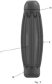
- Figure 2 illustrates a device for transmitting light within a body cavity, where the device comprises a main tubular body 1 having a distal end and a proximal end.
- the tubular body is typically transparent or translucent, but may also be opaque. In some embodiments, the tubular body may even be partly transparent and/or partly translucent and/or partly opaque.
- the distal end of the tubular body 1 is characterised as the end, which is most distant compared to the proximal end to the entry of a body cavity, when the device is inserted in the body cavity. Contrary, is the proximal end closest compared to the distal end to the entry of a body cavity, when the device is inserted in the body cavity.
- the tubular body 1 further comprises two end elements 2A, 2B, preferably circular shaped but the end elements 2A, 2B may also have an outer shape being different, such as squared, such as rugged, such as rectangular or such as coned.
- One end element 2A is arranged at the distal end of the tubular body 1 and the other end element 2B is arranged at the proximal end of the tubular body 1.
- the proximal end of the tubular body and/or the end element 2B arranged at the proximal end is not within the body cavity when the device is inserted herein.
- the device further comprises at least one light source positioned within the main tubular body 1, not shown in fig. 2 , which is configured to provide light at a preselected wavelength and arranged to emit said light to the surroundings of the device.
- An outer part 3, such as a plurality of tubular ribs as shown in fig. 2 is typically attached to the two end elements 2A, 2B and configured to expand the body cavity by providing a bending of an outer surface 4 of the outer part 3 away from the main tubular body 1, such that a void 10 between the main tubular body 1 and the outer part 3 is provided.
- the outer surface 4 of the outer part 3 refers to the surface of the outer part, such as the surface of the ribs.
- the outer part 3 may be pre-bended as shown in fig. 2 .
- the device In order to power the light source(s) the device is configured to receive a battery to be electrically connected to a switch.
- expand the body cavity preferably refers to an increase in a volume or in the three-dimensional-space of the body cavity.
- the device is typically used on an on/off basis, and adapted to be inserted within the body cavity, such as a vagina. Based on the shape of the body cavity, wherein the device is to be inserted, the overall shape of the device may be altered to fit the shape of the body cavity.
- the device is preferably retained in the body cavity for a predetermined amount of time, and then turned off by using a switch before removed. In some embodiments, the device may be turned off outside the body cavity.
- the length of the device is between 3 and 15 cm, such as 5 and 11 cm, and the circumference of the device in a not expanded configuration is between 4 and 12 cm, such as 6 and 10 cm.
- a not expanded configuration preferably refers to the device being in a configuration as illustrated in fig. 2 , where the outer part 3 shown as ribs are limited to a pre-bended, not-bended or in a neutral position, which is preferably the position of ribs when the device is not inserted into a body cavity.
- the void comprises air, typically air comprising oxygen.
- the device preferably comprises a switch located at a predetermined location on the device, electrically connected to an energy source, such as a battery, and the light source, and wherein the switch is configured to turn on/off the light source.
- an energy source such as a battery
- the device may also be in an expanded configuration.
- an expanded configuration preferably refers to the outer part 3 of the device, shown as ribs in figure 3 , being bended to such a degree that the device expand the body cavity when inserted.
- the expanded configuration is achieved by at least one of the end elements 2A, 2B being moveable along a predetermined part of the tubular body 1.
- the moveable end element 2A, 2B preferably comprises a locking element 8 for locking the moveable end element 2A, 2B at a position, wherein the device has expanded the volume of the body cavity.
- the locking element 8 is preferably arranged along and/or within the main tubular 1 at a position preferably being in the proximal end of the main tubular body 1.
- the void 10 is preferably larger and thereby preferably comprises more air, such as air with oxygen, than when the device is in a not expanded configuration.
- the device has increased the volume of the body cavity at least by 3%, such as at least 5%, such as at least 10%, such as at least 20%.
- the increase of volume can be calculated based on a point of reference, which is a volume of the body cavity before the device is inserted therein.
- a point of reference which is a volume of the body cavity before the device is inserted therein.
- an internal diameter of the body cavity is used instead of volume, and wherein an increase in diameter based on a point of reference reflects the amount the device has increased the body cavity, such as at least by 3%, such as at least 5%, such as at least 10%, such as at least 20%.
- the internal diameter preferably refers to an internal diameter measured from one wall of the body cavity to an opposite wall of the body cavity, and typically a point of reference is chosen based on the largest internal diameter before the device is inserted.
- the bending of the outer surface 4 is provided by one end element 2A, 2B being moveable and moved towards the other end element 2A, 2B along the main tubular body 1, and locked by a locking element 8 at a position, wherein the bending of the outer surface has provided an expansion of the body cavity, which preferably increases the inner surface area of the body cavity.
- a locking element 8 is illustrated in fig. 6 in the form of a cam locking mechanism.
- the "inner surface area” preferably refers to a surface area on the inside of the body cavity, being the surface area within the body cavity.
- the outer part 3 is a balloon structure and configured to be inflated, so as to expand the body cavity.
- FIG 4 which is a cross-sectional view of one of the end elements 2A, 2B, one embodiment of the invention is illustrated, where air from the surroundings outside the body cavity can be provided to the void 10 through through-going openings 11 in couplers 9 arranged between the end element 2A, 2B and the main tubular body 1.
- through-going openings 11 are only illustrated in one of the couplers 9, but similar through-going openings 11 is preferably in the coupler being closest to the outer part 3.
- FIG. 5 another embodiment with respect to the position of the through-going openings 11 is illustrated, wherein the through-going openings 11 are positioned within the end element 2A, 2B, for providing air from the surroundings outside the body cavity to the void of the device.
- the through-going openings 11 can be positioned in both end elements 2A, 2B or in one of them.
- the through-going openings 11 are located in the proximal end of the tubular body, being the end element 2B.
- the device further comprising a groove for providing air from the surroundings outside the body cavity to the void 10.
- the environment inside a body cavity is typically anaerobic, meaning that free oxygen is absent, which could favours bacteria and other microorganisms being obligate anaerobes and aerotolerant anaerobes.
- the environment inside the body cavity may change from being anaerobic to contain some free oxygen and thereby be more aerobic.
- the effect obtained by providing a more aerobic environment inside a body cavity can be obtained.
- the device further comprises a penetration cap 5, to guide the device into a body cavity.
- a penetration cap 5 to guide the device into a body cavity.
- the device further comprising a sensor to be electrically connected to the battery and configured to measure pH and/or temperature and/or colour of a tissue and/or colour of a fluid inside the body cavity.
- the fluid is typically but not limited to bodily mucous.
- Measuring pH, temperature, colour of a tissue or the colour of a fluid inside the body cavity using a sensor arranged within the device may be used to provide information regarding a current health status.
- a health status may be used to determine the amount of time the device should be inserted and retained in the body cavity, such as a vagina.
- the senor is arranged in the penetration cap 5 and/or in the outer part.
- the device further comprises an extending element 7, which extends outside the body cavity when the device is inserted within the body cavity. Such as by easing a retrieval of the device from the body cavity.
- an extending element 7 which extends outside the body cavity when the device is inserted within the body cavity.
- the extending element 7 is configured but not limited to facilitate signal transmission from the sensor to a receiving device positioned outside the body cavity during use of the device.
- the extending element 7 further comprises a communication element 6, and wherein the communication element 6 comprises a charger port for charging a battery, such as a rechargeable battery, and/or a transmitter for transmitting sensor data from the sensor.
- the communication element 6 may be arranged in one end of the main tubular body 1.
- the outer part 3 is made of an expandable material, such as rubber, such as latex and/or the outer surface 4 is made of an expandable material, such as rubber, such as latex.
- the expandable material is preferably transparent or translucent, to allowing light to pass through the material.
- the device further comprising an exterior part, wherein the exterior part at least partly covers an outer surface of the body cavity, being the surface, which at least forms the entrance to the body cavity.
- the area forming an entrance to a body cavity is not defined, but may preferably be predetermined for each application.
- the surface which at least forms the entrance around a vagina can be predetermined to be at least the area of a circle around the entrance having at least a diameter of 1 cm, such as at least 2cm, such as at least 2.5 cm, but not exceeding 7.5 cm.
- the exterior part comprises a light source configured to provide light at a predetermined wavelength to the surroundings of the exterior part and electrically connected to the switch.
- the light provided by the light source is at a wavelength of at least 250 nm, such as at least 300 nm, such as at least 350 nm, such as at least 400 nm, but not at a wavelength above 500 nm.
- the device comprising a plurality of light sources, such as a plurality of LEDs, such as a plurality of light bulbs, and wherein each light source has a preselected wavelength.
- the device further comprising a controller for controlling light intensity of the light source.
- a switch may also be arranged in the controller, and configured to turn on/off the light source.
- the device further comprising multiple light sources, such as multiple LEDs, such as multiple light bulbs, and wherein each light source has a preselected wavelength.
- the device comprising a rechargeable battery arranged in the main tubular body 1 and/or in any of the end elements 2A, 2B and/or in the communication element 6, and configured to be recharged by a charger in a charger port.
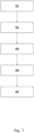
- Figure 7 schematically illustrates through five steps a preferred embodiment of a method for transmitting light within a body cavity, the method comprising:
- the method upon expanding the body, the method further comprising the step of locking the bended outer part by a locking element, such as a cam locking mechanism.
- a locking element such as a cam locking mechanism
- the method upon activating said at least one light source, the method further comprising the step of measuring pH and/or temperature and/or colour of a tissue inside the body cavity and/or colour of a fluid inside the body cavity, and preferably sending said measurements to a receiving device outside the body cavity or storing said measurements in a data storage comprised in the device.
- the invention relates to a device suitable for transmitting light from a device in a body cavity.
- the device includes a main tubular body having a distal end and a proximal end, at least one light source positioned within the main tubular body, an outer part, such as a plurality of tubular ribs and a switch.
- the device is configured to receive a battery to be electrically connected to the switch to power the light source, the battery and the switch preferably positioned within the main body , and wherein the device is adapted to be inserted within the body cavity, such as a vagina.
Landscapes
- Health & Medical Sciences (AREA)
- Engineering & Computer Science (AREA)
- Biomedical Technology (AREA)
- Pathology (AREA)
- Nuclear Medicine, Radiotherapy & Molecular Imaging (AREA)
- Radiology & Medical Imaging (AREA)
- Life Sciences & Earth Sciences (AREA)
- Animal Behavior & Ethology (AREA)
- General Health & Medical Sciences (AREA)
- Public Health (AREA)
- Veterinary Medicine (AREA)
- Measurement Of The Respiration, Hearing Ability, Form, And Blood Characteristics Of Living Organisms (AREA)
- Measuring And Recording Apparatus For Diagnosis (AREA)
Priority Applications (4)
| Application Number | Priority Date | Filing Date | Title |
|---|---|---|---|
| EP22155600.4A EP4223365A1 (fr) | 2022-02-08 | 2022-02-08 | Dispositif de transmission de lumière dans une cavité corporelle |
| PCT/EP2023/053093 WO2023152173A1 (fr) | 2022-02-08 | 2023-02-08 | Dispositif d'émission de lumière à l'intérieur d'une cavité corporelle |
| EP23706538.8A EP4475949A1 (fr) | 2022-02-08 | 2023-02-08 | Dispositif d'émission de lumière à l'intérieur d'une cavité corporelle |
| US18/835,866 US20250205510A1 (en) | 2022-02-08 | 2023-02-08 | A device for transmitting light within a body cavity |
Applications Claiming Priority (1)
| Application Number | Priority Date | Filing Date | Title |
|---|---|---|---|
| EP22155600.4A EP4223365A1 (fr) | 2022-02-08 | 2022-02-08 | Dispositif de transmission de lumière dans une cavité corporelle |
Publications (1)
| Publication Number | Publication Date |
|---|---|
| EP4223365A1 true EP4223365A1 (fr) | 2023-08-09 |
Family
ID=80445705
Family Applications (2)
| Application Number | Title | Priority Date | Filing Date |
|---|---|---|---|
| EP22155600.4A Withdrawn EP4223365A1 (fr) | 2022-02-08 | 2022-02-08 | Dispositif de transmission de lumière dans une cavité corporelle |
| EP23706538.8A Pending EP4475949A1 (fr) | 2022-02-08 | 2023-02-08 | Dispositif d'émission de lumière à l'intérieur d'une cavité corporelle |
Family Applications After (1)
| Application Number | Title | Priority Date | Filing Date |
|---|---|---|---|
| EP23706538.8A Pending EP4475949A1 (fr) | 2022-02-08 | 2023-02-08 | Dispositif d'émission de lumière à l'intérieur d'une cavité corporelle |
Country Status (3)
| Country | Link |
|---|---|
| US (1) | US20250205510A1 (fr) |
| EP (2) | EP4223365A1 (fr) |
| WO (1) | WO2023152173A1 (fr) |
Families Citing this family (1)
| Publication number | Priority date | Publication date | Assignee | Title |
|---|---|---|---|---|
| ZA202209265B (en) * | 2022-03-09 | 2023-05-31 | Zero Candida Ltd | Devices and method for prevention and treatment of fungal and bacterial microorganisms |
Citations (3)
| Publication number | Priority date | Publication date | Assignee | Title |
|---|---|---|---|---|
| US20160008624A1 (en) * | 2014-07-11 | 2016-01-14 | Jessica D Grossman | Devices and methods for treatment inside a body cavity |
| US20160059034A1 (en) * | 2014-07-03 | 2016-03-03 | Gregg Alan Klang | Led based vaginal light therapy device |
| WO2017070155A1 (fr) * | 2015-10-19 | 2017-04-27 | Christoph Scharf | Dispositifs pour l'émission de lumière thérapeutique réglée de manière répétée et dispositifs pour le traitement de l'empoisonnement au monoxyde de carbone |
Family Cites Families (7)
| Publication number | Priority date | Publication date | Assignee | Title |
|---|---|---|---|---|
| US6159236A (en) * | 1999-01-28 | 2000-12-12 | Advanced Photodynamic Technologies, Inc. | Expandable treatment device for photodynamic therapy and method of using same |
| US6749623B1 (en) * | 2000-03-31 | 2004-06-15 | Richard A Hsi | Method and apparatus for catheter phototherapy with dose sensing |
| GB201221123D0 (en) * | 2012-11-23 | 2013-01-09 | Photocure As | Device for photodynamic treatment |
| GB201522398D0 (en) * | 2015-12-18 | 2016-02-03 | Photocure As | Device for photodynamic therapy |
| MX2018014694A (es) * | 2016-05-31 | 2019-05-16 | Cedars Sinai Medical Center | Terapia ultravioleta interna. |
| KR102136840B1 (ko) * | 2019-11-14 | 2020-07-23 | 부경대학교 산학협력단 | 광 조사 치료가 가능한 의료용 삽관 장치 |
| EP3875146A1 (fr) * | 2020-03-02 | 2021-09-08 | RP-Technik GmbH | Éclairage, en particulier destiné à la réduction des germes, pourvu, de préférence d'au moins deux sources lumineuses, ainsi que procédé d'utilisation de l'éclairage comme désinfectant mobile |
-
2022
- 2022-02-08 EP EP22155600.4A patent/EP4223365A1/fr not_active Withdrawn
-
2023
- 2023-02-08 US US18/835,866 patent/US20250205510A1/en active Pending
- 2023-02-08 EP EP23706538.8A patent/EP4475949A1/fr active Pending
- 2023-02-08 WO PCT/EP2023/053093 patent/WO2023152173A1/fr not_active Ceased
Patent Citations (3)
| Publication number | Priority date | Publication date | Assignee | Title |
|---|---|---|---|---|
| US20160059034A1 (en) * | 2014-07-03 | 2016-03-03 | Gregg Alan Klang | Led based vaginal light therapy device |
| US20160008624A1 (en) * | 2014-07-11 | 2016-01-14 | Jessica D Grossman | Devices and methods for treatment inside a body cavity |
| WO2017070155A1 (fr) * | 2015-10-19 | 2017-04-27 | Christoph Scharf | Dispositifs pour l'émission de lumière thérapeutique réglée de manière répétée et dispositifs pour le traitement de l'empoisonnement au monoxyde de carbone |
Also Published As
| Publication number | Publication date |
|---|---|
| EP4475949A1 (fr) | 2024-12-18 |
| US20250205510A1 (en) | 2025-06-26 |
| WO2023152173A1 (fr) | 2023-08-17 |
Similar Documents
| Publication | Publication Date | Title |
|---|---|---|
| US20160008624A1 (en) | Devices and methods for treatment inside a body cavity | |
| EP4223365A1 (fr) | Dispositif de transmission de lumière dans une cavité corporelle | |
| EP3738640B1 (fr) | Cathéter urinaire incurvé | |
| CN107648720B (zh) | 一种内置式导尿管 | |
| CA2507142A1 (fr) | Appareils, dispositifs et methodes pour la contraception, la conception et la grossesse | |
| GB2599850A (en) | Urinary catheter | |
| BR0108182B1 (pt) | aparelho para o tratamento de incontinência urinária com suprimento de energia sem fio. | |
| NZ197025A (en) | Device to assist exercise and control of sphincter type muscles | |
| ATE273719T1 (de) | Desinfizierendes kunststoffschaummaterial | |
| US12220600B2 (en) | Light-based vaginal therapy devices and methods for use | |
| US20250025670A1 (en) | Apparatus and method for inactivating infectious organisms in human body | |
| CN105343986A (zh) | 一种医用抗菌导尿管 | |
| WO2025032575A1 (fr) | Système de cathéter de diagnostic contrôlable | |
| CN103251467A (zh) | 一种杀菌型阴道模具 | |
| CN102512314A (zh) | 引导式臭氧妇科治疗仪 | |
| CN224056445U (zh) | 一次性可膨胀式尿道扩张包 | |
| CN205379550U (zh) | 一种侵入式多功能妇科疾病治疗装置 | |
| CN111166944B (zh) | 引流装置 | |
| CN214388498U (zh) | 一种自消毒阴道抑菌吸附器 | |
| CN210992521U (zh) | 一种肝胆胰脾外科用的扩张导管 | |
| TIERNEY et al. | A NOVEL IN VITRO URETHRA MODEL TO DEMONSTRATE BACTERIAL DISPLACEMENT DURING URINARY CATHETER INSERTION | |
| CN114788759A (zh) | 一种泌尿外科手术后护理用包扎套 | |
| EP4138997A1 (fr) | Dispositifs de thérapie vaginale par lumière et procédés d'utilisation correspondants | |
| ES2577537B1 (es) | Colector y separador de orina para mujer | |
| BG4013U1 (bg) | Вагинален протектор |
Legal Events
| Date | Code | Title | Description |
|---|---|---|---|
| PUAI | Public reference made under article 153(3) epc to a published international application that has entered the european phase |
Free format text: ORIGINAL CODE: 0009012 |
|
| STAA | Information on the status of an ep patent application or granted ep patent |
Free format text: STATUS: THE APPLICATION HAS BEEN PUBLISHED |
|
| AK | Designated contracting states |
Kind code of ref document: A1 Designated state(s): AL AT BE BG CH CY CZ DE DK EE ES FI FR GB GR HR HU IE IS IT LI LT LU LV MC MK MT NL NO PL PT RO RS SE SI SK SM TR |
|
| STAA | Information on the status of an ep patent application or granted ep patent |
Free format text: STATUS: REQUEST FOR EXAMINATION WAS MADE |
|
| RBV | Designated contracting states (corrected) |
Designated state(s): AL AT BE BG CH CY CZ DE DK EE ES FI FR GB GR HR HU IE IS IT LI LT LU LV MC MK MT NL NO PL PT RO RS SE SI SK SM TR |
|
| 17P | Request for examination filed |
Effective date: 20240208 |
|
| GRAP | Despatch of communication of intention to grant a patent |
Free format text: ORIGINAL CODE: EPIDOSNIGR1 |
|
| STAA | Information on the status of an ep patent application or granted ep patent |
Free format text: STATUS: GRANT OF PATENT IS INTENDED |
|
| INTG | Intention to grant announced |
Effective date: 20250805 |
|
| STAA | Information on the status of an ep patent application or granted ep patent |
Free format text: STATUS: THE APPLICATION IS DEEMED TO BE WITHDRAWN |
|
| 18D | Application deemed to be withdrawn |
Effective date: 20251206 |