EP4223481A1 - Élément de boîtier pour équipement électrique ayant un joint intégré et procédé de fabrication d'un tel élément de boîtier pour équipement électrique - Google Patents
Élément de boîtier pour équipement électrique ayant un joint intégré et procédé de fabrication d'un tel élément de boîtier pour équipement électrique Download PDFInfo
- Publication number
- EP4223481A1 EP4223481A1 EP22155509.7A EP22155509A EP4223481A1 EP 4223481 A1 EP4223481 A1 EP 4223481A1 EP 22155509 A EP22155509 A EP 22155509A EP 4223481 A1 EP4223481 A1 EP 4223481A1
- Authority
- EP
- European Patent Office
- Prior art keywords
- gasket
- electrical equipment
- equipment housing
- housing element
- shell
- Prior art date
- Legal status (The legal status is an assumption and is not a legal conclusion. Google has not performed a legal analysis and makes no representation as to the accuracy of the status listed.)
- Granted
Links
Images

Classifications
-
- F—MECHANICAL ENGINEERING; LIGHTING; HEATING; WEAPONS; BLASTING
- F16—ENGINEERING ELEMENTS AND UNITS; GENERAL MEASURES FOR PRODUCING AND MAINTAINING EFFECTIVE FUNCTIONING OF MACHINES OR INSTALLATIONS; THERMAL INSULATION IN GENERAL
- F16J—PISTONS; CYLINDERS; SEALINGS
- F16J15/00—Sealings
- F16J15/02—Sealings between relatively-stationary surfaces
- F16J15/06—Sealings between relatively-stationary surfaces with solid packing compressed between sealing surfaces
- F16J15/10—Sealings between relatively-stationary surfaces with solid packing compressed between sealing surfaces with non-metallic packing
- F16J15/108—Special methods for making a non-metallic packing
-
- H—ELECTRICITY
- H05—ELECTRIC TECHNIQUES NOT OTHERWISE PROVIDED FOR
- H05K—PRINTED CIRCUITS; CASINGS OR CONSTRUCTIONAL DETAILS OF ELECTRIC APPARATUS; MANUFACTURE OF ASSEMBLAGES OF ELECTRICAL COMPONENTS
- H05K5/00—Casings, cabinets or drawers for electric apparatus
- H05K5/06—Hermetically-sealed casings
-
- B—PERFORMING OPERATIONS; TRANSPORTING
- B29—WORKING OF PLASTICS; WORKING OF SUBSTANCES IN A PLASTIC STATE IN GENERAL
- B29C—SHAPING OR JOINING OF PLASTICS; SHAPING OF MATERIAL IN A PLASTIC STATE, NOT OTHERWISE PROVIDED FOR; AFTER-TREATMENT OF THE SHAPED PRODUCTS, e.g. REPAIRING
- B29C45/00—Injection moulding, i.e. forcing the required volume of moulding material through a nozzle into a closed mould; Apparatus therefor
- B29C45/14—Injection moulding, i.e. forcing the required volume of moulding material through a nozzle into a closed mould; Apparatus therefor incorporating preformed parts or layers, e.g. injection moulding around inserts or for coating articles
- B29C45/14336—Coating a portion of the article, e.g. the edge of the article
-
- B—PERFORMING OPERATIONS; TRANSPORTING
- B29—WORKING OF PLASTICS; WORKING OF SUBSTANCES IN A PLASTIC STATE IN GENERAL
- B29C—SHAPING OR JOINING OF PLASTICS; SHAPING OF MATERIAL IN A PLASTIC STATE, NOT OTHERWISE PROVIDED FOR; AFTER-TREATMENT OF THE SHAPED PRODUCTS, e.g. REPAIRING
- B29C45/00—Injection moulding, i.e. forcing the required volume of moulding material through a nozzle into a closed mould; Apparatus therefor
- B29C45/16—Making multilayered or multicoloured articles
- B29C45/1642—Making multilayered or multicoloured articles having a "sandwich" structure
-
- B—PERFORMING OPERATIONS; TRANSPORTING
- B29—WORKING OF PLASTICS; WORKING OF SUBSTANCES IN A PLASTIC STATE IN GENERAL
- B29C—SHAPING OR JOINING OF PLASTICS; SHAPING OF MATERIAL IN A PLASTIC STATE, NOT OTHERWISE PROVIDED FOR; AFTER-TREATMENT OF THE SHAPED PRODUCTS, e.g. REPAIRING
- B29C45/00—Injection moulding, i.e. forcing the required volume of moulding material through a nozzle into a closed mould; Apparatus therefor
- B29C45/16—Making multilayered or multicoloured articles
- B29C45/1676—Making multilayered or multicoloured articles using a soft material and a rigid material, e.g. making articles with a sealing part
-
- H—ELECTRICITY
- H01—ELECTRIC ELEMENTS
- H01R—ELECTRICALLY-CONDUCTIVE CONNECTIONS; STRUCTURAL ASSOCIATIONS OF A PLURALITY OF MUTUALLY-INSULATED ELECTRICAL CONNECTING ELEMENTS; COUPLING DEVICES; CURRENT COLLECTORS
- H01R13/00—Details of coupling devices of the kinds covered by groups H01R12/70 or H01R24/00 - H01R33/00
- H01R13/46—Bases; Cases
- H01R13/52—Dustproof, splashproof, drip-proof, waterproof, or flameproof cases
- H01R13/521—Sealing between contact members and housing, e.g. sealing insert
-
- H—ELECTRICITY
- H05—ELECTRIC TECHNIQUES NOT OTHERWISE PROVIDED FOR
- H05K—PRINTED CIRCUITS; CASINGS OR CONSTRUCTIONAL DETAILS OF ELECTRIC APPARATUS; MANUFACTURE OF ASSEMBLAGES OF ELECTRICAL COMPONENTS
- H05K5/00—Casings, cabinets or drawers for electric apparatus
- H05K5/02—Details
- H05K5/0217—Mechanical details of casings
-
- B—PERFORMING OPERATIONS; TRANSPORTING
- B29—WORKING OF PLASTICS; WORKING OF SUBSTANCES IN A PLASTIC STATE IN GENERAL
- B29C—SHAPING OR JOINING OF PLASTICS; SHAPING OF MATERIAL IN A PLASTIC STATE, NOT OTHERWISE PROVIDED FOR; AFTER-TREATMENT OF THE SHAPED PRODUCTS, e.g. REPAIRING
- B29C45/00—Injection moulding, i.e. forcing the required volume of moulding material through a nozzle into a closed mould; Apparatus therefor
- B29C45/14—Injection moulding, i.e. forcing the required volume of moulding material through a nozzle into a closed mould; Apparatus therefor incorporating preformed parts or layers, e.g. injection moulding around inserts or for coating articles
- B29C45/14336—Coating a portion of the article, e.g. the edge of the article
- B29C2045/14459—Coating a portion of the article, e.g. the edge of the article injecting seal elements
-
- B—PERFORMING OPERATIONS; TRANSPORTING
- B29—WORKING OF PLASTICS; WORKING OF SUBSTANCES IN A PLASTIC STATE IN GENERAL
- B29K—INDEXING SCHEME ASSOCIATED WITH SUBCLASSES B29B, B29C OR B29D, RELATING TO MOULDING MATERIALS OR TO MATERIALS FOR MOULDS, REINFORCEMENTS, FILLERS OR PREFORMED PARTS, e.g. INSERTS
- B29K2995/00—Properties of moulding materials, reinforcements, fillers, preformed parts or moulds
- B29K2995/0037—Other properties
- B29K2995/0065—Permeability to gases
-
- B—PERFORMING OPERATIONS; TRANSPORTING
- B29—WORKING OF PLASTICS; WORKING OF SUBSTANCES IN A PLASTIC STATE IN GENERAL
- B29L—INDEXING SCHEME ASSOCIATED WITH SUBCLASS B29C, RELATING TO PARTICULAR ARTICLES
- B29L2031/00—Other particular articles
- B29L2031/26—Sealing devices, e.g. packaging for pistons or pipe joints
Definitions
- the present invention relates to an electrical equipment housing element with an integrated gasket comprising a body of the electrical equipment housing element and an integrated gasket, in particular gasket with gas barrier properties.
- the invention relates also to a method of manufacturing of such electrical equipment housing elements.
- 2K injection molding is commonly used in order to create elements made of two different materials, for example hard thermoplastic part with well adhering soft thermoplastic.
- the 2K injection molding is also known as two-component injection molding or two-color molding.
- sealing in gas insulated electrical devices is application of the O-rings made of vulcanized rubber, like EPDM.
- O-rings made of vulcanized rubber, like EPDM.
- Such type of sealing is applied separately during device assembly and is used mainly in epoxy casted parts.
- epoxy resin to more sustainable thermoplastic materials, therefore it would be of interest to also switch from standard rubber sealing to thermoplastic one.
- sealing system can be integrated with device during the same injection molding process by means of two-component - 2K - injection molding.
- EP0792095A2 discloses a one-piece seal comprising protruding areas which overcomes this problem.
- the seal is produced in one manufacturing step at the same time as the appropriate part of the housing - a lid or a body. During manufacturing process, after the end of the moulding step, mobile element of a counterdie form creates a groove in the lid or in the body.
- the groove is a space which dimensions are corresponding to those of the seal. Into this space there is injected plastic material that forms the seal.
- the plastic material is normally softer than the material forming the lid or the body.
- the box is made of a thermoplastic material and the integrated seal is made of thermoplastic elastomer.
- EP1045174 discloses a gasket fitted to a frame which hermetically seals the joint surface between a cover body and a main body in lightweight electronic equipment. Process of production of such gasket is also disclosed.
- the gasket is designated to be used for example in hard disc equipment of a computer and its application completely keeps water and air away from the electronic equipment and thus it gives high tightness.
- the frame of the body comprises an outer frame body and an inner frame which are integrated with each other.
- the frame is made of a thermoplastic resin.
- the gasket is integrated with the outer frame body and inner frame body and comprises an elastic body.
- the gasket is made of a thermoplastic elastomer.
- Fixing the gasket to the lateral sides of the outer frame body and the inner frame body leads to integration of the gasket with inner frame body and outer frame body.
- the fixing process covers integration by fusion adhesion or integration by two-color molding method.
- the frame of the body might be made of synthetic resin, especially thermoplastic resin and the elastic body constituting the gasket might be of thermoplastic elastomer.
- EP3310547B1 discloses a plastic housing with housing body made of first plastic material, duroplastic or thermoplastic, which is modified with heat-conductive fillers.
- the housing can be made of a thermoplastic material reinforced with the same thermally conductive fillers, such as polyamide or polyphenylene sulfide.
- the housing body has got at least one sealing element which is made of second plastic material, for example it might be made of thermoplastic elastomer.
- the housing body and the sealing element are connected.
- the sealing element is bonded and/or injected onto the housing body in a formfitting manner.
- the housing has also at least one covering cap, which is placed on the housing body at an end portion. The sealing element seals a connection between the housing body and the covering cap.
- Patent EP3310547B1 discloses also method of a production of the plastic housing by means of injection-moulding devices.
- Method of production comprises step of injection of first plastic material into a first cavity of an injection mould in order to produce housing body and step of withdrawal of hydraulic cores in the injection mould in order to configure a second cavity in the injection mould in order to produce the sealing element.
- resilient plastic is injected by means of a second injection unit, which configures the sealing element. Therefore, the sealing element is bonded to the housing body.
- the covering cap is placed on the housing body.
- EP0245975B1 discloses an electrical connector.
- This document discloses also a method of making a connector housing by dual injection molding.
- the connector comprises a plug and receptacle housing members, each member having a rigid and a flexible portion secured to one end thereof.
- the connector contains at least one electrical terminal receiving passageway extending through the rigid and flexible portions.
- the flexible portions of the passageways accommodate and engages a variety of wire sizes terminated to electrical terminals. Electrical terminals are received and disposed in the passageways of the assembled connector.
- the connector has got a sealing part made during dual injection molding.
- Manufacturing process of electrical connector covers introducing a first plastic material having flexible or rigid characteristics into a first section of a connector housing forming area in a mold and preventing the first plastic material from entering a second section of the connector housing forming area of the mold.
- a second plastic material is introduced, which has rigid or flexible characteristics opposite to the first plastic material into the second section of the connector housing forming area so that the connector housing so that the connector housing is formed and chemical bonding takes place at an interface between the first and second plastic materials causing them to adhere.
- thermoplastics thermoplastic elastomers and thermosetting rubbers might be used and in order to increase chemical affinity between these materials. It is preferred when a similarly based polymer is used as a first and second plastic material.
- WO20100 86144A1 discloses a seal produced by injection molding according to the sandwich technology or with usage of by multi-component injection molding.
- the seal comprises a core made of a hard plastic and a skin made of a comparatively soft plastic. At lase one core end passes through the skin. This core end passes to the outside to form an opening or passes in a narrowing manner up to the edge of the skin without forming an opening. What is more, in the interior of the core a dimensionally stable carrier might be arranged.
- materials of the seal are injected one after the other to melt into the cavity of injection mold.
- the skin component is injected, which extends progressively in the cavity.
- the core component is injected into the cavity.
- the core component then progresses in the cavity, at least partially surrounded by the skin component.
- Such seal produced by presented method, needs to be assembled into parts where a sealing should be realized. This seal is not connected nor bonded with sealed components.
- the invention presents the means to improve sealing system in the electrical device.
- the invention presents how to increase the gas tightness by application of 2K integrated gasket with embedded gas barrier made by means of sandwich molding.
- the invention concerns an electrical equipment housing element with an integrated gasket comprising a body of the electrical equipment housing element and an integrated gasket.
- the essence of the invention is that the gasket is a core-shell gasket having a core formed of thermoplastic elastomer and the shell formed of a thermoplastic polymer having high gas barrier properties, wherein the body of the electrical equipment housing element and the shell of the gasket are chemically or chemically-mechanically bonded in 2K injection molding process.
- thermoplastic material In case when a main body of the electrical device is manufactured from thermoplastic material by means of injection molding, it is beneficial to fabricate in the same process the integrated sealing by means of 2K injection molding. Additionally, the fabricated thermoplastic gasket has an advanced core-shell barrier structure made by means of a sandwich molding process, with a shell material possessing high gas barrier properties. The proposed solution allows to obtain more reliable sealing system manufactured simultaneously during injection molding of electrical device housing.
- the core of the gasket is formed of thermoplastic elastomer having a low compression set values equal to or less than 10% at temperature of 23°C, and equal to or less than 30% at temperature of 70°C.
- Low compression set is understood as an amount of permanent deformation that a product sustains when put under pressure or force according to ISO 815 and ASTM D395 standard.
- the shell of the gasket is formed of an ethylene-vinyl alcohol copolymer or a thermoplastic elastomer with a low carbon dioxide gas permeability values equal to or less than 65 Barrer at temperature of 25°C and equal to or less than 250 Barrer at temperature of 75°C.
- Barrer is understood as a non-SI unit of gas permeability. It gives information concerning measure of the rate of fluid flow passing through an area of material with a thickness driven by a given pressure.
- Another aspect of invention concerns method of manufacturing an electrical equipment housing element with integrated gasket. 2K injection molding process comprising the steps of:
- step b) a core-shell gasket is formed in sandwich injection molding process wherein a core of the gasket is formed of thermoplastic elastomer whereas the shell of the gasket is formed of material of polymers having high gas barrier properties.
- the core of the gasket is formed of thermoplastic elastomer having a low compression set with the values equal to or less than 10% at temperature of 23°C and equal to or less than 30% at temperature of 70°C.
- the shell of the gasket is formed of an ethylene-vinyl alcohol copolymer or thermoplastic elastomer with a low carbon dioxide gas permeability values equal to or less than 65 Barrer at temperature of 25°C and equal to or less than 250 Barrer at temperature of 75°C.
- the body of the electrical equipment housing element is molded from high strength and dielectric thermoplastic material, or thermoplastic composite material.
- Gaskets according to the invention provide improved sealing performance.
- Gaskets have shell formed of a thermoplastic polymer having high gas barrier properties and provide gas tightness and possibility to use electrical devices regardless of external conditions, especially when they are exposed to environment or when should provide gas tightness. What is more, increased gas tightness protects internal space of electrical equipment against leakage to the outside and pressure loss of dielectric protection gases placed inside the housing.
- the invention may, for example, be applied in such electrical equipment as bushings, cable sockets, busbar sockets.
- An electrical equipment housing element with an integrated gasket comprises a body 1 of the electrical equipment housing, a conductor 2 being the electrical equipment and the integrated gasket 3.
- the gasket 3 integrated with the body 1 of the electrical equipment housing it is understood that the gasket 3 is inseparably, chemically or chemically-mechanically bonded with the housing body 1.
- the housing body 1 of the electrical equipment housing is integrated with the gasket 3 in 2K injection molding process, during which chemical or chemical-mechanical bonding between the housing and the gasket takes place.
- Gasket 3 is a core shell gasket. It has a core 4 formed of thermoplastic elastomer and the shell 5 formed of thermoplastic polymer having high gas barrier properties. Gasket 3 ensures gas tightness of the electrical equipment housing.
- the core 4 of the gasket 3 is formed of thermoplastic elastomer having a low compression set according to standard ISO 815 and ASTM D395 with the values equal to or less than 10% at temperature of 23°C and equal to or less than 30% at temperature of 70°C.
- Low compression set is defined as an amount of permanent deformation that a product sustains when put under pressure or force.
- Low compression set means that after removal of pressure or force the product has relatively small deformations.
- the shell 5 of the gasket 3 is formed of an ethylene-vinyl alcohol copolymer or thermoplastic elastomer with low gas permeability, which protects internal space of electrical equipment against leakage to the outside and pressure loss of dielectric protection gases placed inside the housing.
- the shell 5 is characterized by a low carbon dioxide gas permeability values equal to or less than 65 Barrer at temperature of 25°C and equal to or less than 250 Barrer at temperature of 75°C.
- the body 1 of the electrical equipment housing element is molded from high strength and dielectric thermoplastic material, or thermoplastic composite material, which possess the adequate dielectric properties. It provides appropriate proprieties of the housing, which might be used in different conditions as well as protects users or other people against damaged electrical equipment.
- the above presented electrical equipment housing element with integrated gasket 3 is manufactured in one 2K injection molding process.
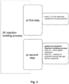
- the manufacturing process has following steps of 2K injection molding process:
- the manufacturing process covers also sandwich injection molding process which is defined in a such way, that two or more polymers are injected one after the another through the same gate in one or more cavities.
- sandwich injection molding process which is defined in a such way, that two or more polymers are injected one after the another through the same gate in one or more cavities.
- first step of injecting first material and second step of injecting second material, so both materials are injected into the mould one after another.
- a thin boundary layer of the first injected material solidifies, while the core remains plastic.
- the second subsequently injected material fills the core and the first material takes over the function of the skin.
- the process can be used for all thermoplastic materials.
- the process of forming the body 1 of the electrical equipment housing element is generally used to manufacture main body 1 from high strength thermoplastic material, or thermoplastic composite material possessing the dielectric properties, which are necessary for housings which might be used as external housings.
- the process of forming the body 1 covers first step of 2K injection molding. In this step electrical equipment is inserted to the mould and these internal parts are over-moulded with high strength thermoplastic material, or thermoplastic composite material.
- the second step is used to form sealing system with high gas barrier properties. It also requires appropriate selection of sealing material which have to allow for good integration of sealing with the housing with electrical device. Factors like good adhesion or modification of the interface between the body 1 and the gasket 3 by mechanical interlocking, should be considered.
- the process of forming the body 1 of the electrical equipment housing element covers also final step of 2K injection molding, during which final product with integrated gasket 3 is demolded.
- the core 4 material can be selected from the group of thermoplastic elastomers having the low compression set values equal to or less than 10% at temperature of 23°C and equal to or less than 30% at temperature of 70°C.
- a material for the shell 5 of the gasket 3 can be chosen from the polymers possessing high gas barrier properties, for example ethylene-vinyl alcohol copolymer or thermoplastic elastomers with low carbon dioxide gas permeability, so with values equal to or less than 65 Barrer at temperature of 25°C and equal to or less than 250 Barrer at temperature of 75°C.
- the applied core material will maintain proper mechanical functionality of the gasket 3, while the shell material will ensure gas tightness of the electrical device.
- thermoplastic elastomers for the core 4 and polymers for the shell 5 can be selected from the following types of materials:
- the body 1 of the electrical equipment housing element is molded from high strength and dielectric thermoplastic material, or thermoplastic composite material, including but not limited to acetal and ketal based polymers and copolymers, polyesters, with polyethylene terephthalate and polybutylene terephthalate; polycarbonate, polystyrene, polyether sulfone, polyphenylene sulfone, polysulfone, and polytetrafluoroethylene.
- polymers can also be implemented, including but not limited to polyvinyl chloride, polyethylene, polypropylene, polyetherimide, polyphenylene sulfide, polyether ether ketone, polyphthalamide, polyoxymethylene, phenolformaldehyde, unsatured polyester, polyurethane, polyimide, polyamide, polyvinyl alcohol, polyvinylidene chloride, polyacrylonitrile and polyalkylene paraoxybenzoate.
- the composite can include a variety of types of fibers, including but not limited to glass fiber, basalt fiber, wool, silk, cotton, rayon, cellulose, cellulose acetate, flax, ramie, jute and aramid fibers.
- additives can be used to improve the qualities of the materials, including but not limited to the mechanical and thermal stability, chemical resistance, insulation property and flammability.
- the additives can include, but are not limited to, ceramics, alumina, calcium silicate, flame retardants and clays.
- the materials used to produce the body 1 of the electrical equipment housing with the integrated gasket 3 can be characterized by a hardness relationship between materials of the body 1 and materials of the gasket 3.
- the hardness of the gasket 3 is measured according to ISO 48 and ASTM D2240-00 standard for test method for rubber property, also called as durometer hardness.
- the hardness of the body 1 of the electrical equipment housing is measured according to ISO 2039-2 standard, which specifies a method for determining the indentation hardness of plastics by means of the Rockwell hardness tester using the Rockwell M, L and R hardness scales.
- materials which have been used to produce the body 1 of the electrical equipment housing and gasket 3 with the core 4 and with the shell 5, have following hardness relationship between them:
- the hardness of the shell 5 of the gasket 3 is not greater than that of the core 4 of the gasket 3, while the hardness of the shell 5 and of core 3 is not greater than the hardness of the body 1.
- the use of low-hardness materials as the shell 5 allows for better filling of unevenness on the interface between the gasket 3 and the sealed element - body 1.
Landscapes
- Engineering & Computer Science (AREA)
- Mechanical Engineering (AREA)
- Manufacturing & Machinery (AREA)
- Microelectronics & Electronic Packaging (AREA)
- General Engineering & Computer Science (AREA)
- Casings For Electric Apparatus (AREA)
- Injection Moulding Of Plastics Or The Like (AREA)
Priority Applications (3)
| Application Number | Priority Date | Filing Date | Title |
|---|---|---|---|
| ES22155509T ES2995031T3 (en) | 2022-02-07 | 2022-02-07 | An electrical equipment housing element with an integrated gasket and a method of manufacturing of such an electrical equipment housing element |
| EP22155509.7A EP4223481B1 (fr) | 2022-02-07 | 2022-02-07 | Élément de boîtier pour équipement électrique ayant un joint intégré et procédé de fabrication d'un tel élément de boîtier pour équipement électrique |
| CN202310068089.4A CN116567979A (zh) | 2022-02-07 | 2023-02-06 | 具有集成垫片的电气设备外壳元件及其制造方法 |
Applications Claiming Priority (1)
| Application Number | Priority Date | Filing Date | Title |
|---|---|---|---|
| EP22155509.7A EP4223481B1 (fr) | 2022-02-07 | 2022-02-07 | Élément de boîtier pour équipement électrique ayant un joint intégré et procédé de fabrication d'un tel élément de boîtier pour équipement électrique |
Publications (2)
| Publication Number | Publication Date |
|---|---|
| EP4223481A1 true EP4223481A1 (fr) | 2023-08-09 |
| EP4223481B1 EP4223481B1 (fr) | 2024-08-07 |
Family
ID=80445723
Family Applications (1)
| Application Number | Title | Priority Date | Filing Date |
|---|---|---|---|
| EP22155509.7A Active EP4223481B1 (fr) | 2022-02-07 | 2022-02-07 | Élément de boîtier pour équipement électrique ayant un joint intégré et procédé de fabrication d'un tel élément de boîtier pour équipement électrique |
Country Status (3)
| Country | Link |
|---|---|
| EP (1) | EP4223481B1 (fr) |
| CN (1) | CN116567979A (fr) |
| ES (1) | ES2995031T3 (fr) |
Citations (9)
| Publication number | Priority date | Publication date | Assignee | Title |
|---|---|---|---|---|
| EP0245975B1 (fr) | 1986-05-13 | 1992-08-12 | Amp Incorporated | Connecteur étanche à l'environnement |
| EP0552040A1 (fr) * | 1992-01-15 | 1993-07-21 | Patrick Arthur Leach | Procédé et appareil pour la fabrication d'un cône de haut-parleur et d'un équipage de suspension |
| EP0792095A2 (fr) | 1996-02-20 | 1997-08-27 | ABB Lucasystem S.r.L. | Joint pour une boîte étanche |
| DE19743134A1 (de) * | 1997-09-30 | 1999-04-01 | Hoechst Ag | Formteile aus Polyacetal mit direkt angeformten Funktionselementen aus thermoplastischen Elastomeren |
| DE19848246A1 (de) * | 1998-10-20 | 2000-04-27 | Krauss Maffei Kunststofftech | Thermoplastteil mit eingespritzter Elastomerdichtung |
| EP1045174A2 (fr) | 1999-04-13 | 2000-10-18 | Bridgestone Corporation | Joint monté sur un cadre et sa méthode de production |
| DE102004031314A1 (de) * | 2004-06-29 | 2006-01-19 | Robert Bosch Gmbh | Gehäuseteil für eine Antriebseinheit, sowie Verfahren und Werkzeug zur Herstellung eines solchen |
| WO2010086144A1 (fr) | 2009-01-27 | 2010-08-05 | Neo-Plastic Dr. Doetsch Diespeck Gmbh | Joint en sandwich avec noyau traversant et commande de procédé avec dispositif de trop-plein |
| EP3310547B1 (fr) | 2015-06-17 | 2021-11-24 | Robert Bosch GmbH | Boîtier en matière plastique et procédé pour sa fabrication |
-
2022
- 2022-02-07 ES ES22155509T patent/ES2995031T3/es active Active
- 2022-02-07 EP EP22155509.7A patent/EP4223481B1/fr active Active
-
2023
- 2023-02-06 CN CN202310068089.4A patent/CN116567979A/zh active Pending
Patent Citations (9)
| Publication number | Priority date | Publication date | Assignee | Title |
|---|---|---|---|---|
| EP0245975B1 (fr) | 1986-05-13 | 1992-08-12 | Amp Incorporated | Connecteur étanche à l'environnement |
| EP0552040A1 (fr) * | 1992-01-15 | 1993-07-21 | Patrick Arthur Leach | Procédé et appareil pour la fabrication d'un cône de haut-parleur et d'un équipage de suspension |
| EP0792095A2 (fr) | 1996-02-20 | 1997-08-27 | ABB Lucasystem S.r.L. | Joint pour une boîte étanche |
| DE19743134A1 (de) * | 1997-09-30 | 1999-04-01 | Hoechst Ag | Formteile aus Polyacetal mit direkt angeformten Funktionselementen aus thermoplastischen Elastomeren |
| DE19848246A1 (de) * | 1998-10-20 | 2000-04-27 | Krauss Maffei Kunststofftech | Thermoplastteil mit eingespritzter Elastomerdichtung |
| EP1045174A2 (fr) | 1999-04-13 | 2000-10-18 | Bridgestone Corporation | Joint monté sur un cadre et sa méthode de production |
| DE102004031314A1 (de) * | 2004-06-29 | 2006-01-19 | Robert Bosch Gmbh | Gehäuseteil für eine Antriebseinheit, sowie Verfahren und Werkzeug zur Herstellung eines solchen |
| WO2010086144A1 (fr) | 2009-01-27 | 2010-08-05 | Neo-Plastic Dr. Doetsch Diespeck Gmbh | Joint en sandwich avec noyau traversant et commande de procédé avec dispositif de trop-plein |
| EP3310547B1 (fr) | 2015-06-17 | 2021-11-24 | Robert Bosch GmbH | Boîtier en matière plastique et procédé pour sa fabrication |
Also Published As
| Publication number | Publication date |
|---|---|
| ES2995031T3 (en) | 2025-02-05 |
| EP4223481B1 (fr) | 2024-08-07 |
| CN116567979A (zh) | 2023-08-08 |
Similar Documents
| Publication | Publication Date | Title |
|---|---|---|
| CN1809733B (zh) | 温度传感器 | |
| EP1133222B1 (fr) | Boitier en resine alliant permeabilite a l'air et impermeabilite a l'eau, et moule permettant de produire ledit boitier | |
| US8272895B2 (en) | Sealed electrical connector | |
| CN102754286B (zh) | 具有垫密封件的连接器壳体 | |
| US8759700B2 (en) | Push switch and method of manufacturing the same | |
| US6482021B2 (en) | Structure of waterproof portion of waterproof connector | |
| KR100367568B1 (ko) | 프리몰드 부재를 사용한 복합 일체 성형품 | |
| CN112303231A (zh) | 密封部件和防水结构 | |
| CN104340027A (zh) | 带有传感器的防护装置及该防护装置的端部的成型方法 | |
| CN102377069B (zh) | 防水型电连接器、防水型电连接器的组装方法 | |
| EP4223481B1 (fr) | Élément de boîtier pour équipement électrique ayant un joint intégré et procédé de fabrication d'un tel élément de boîtier pour équipement électrique | |
| CN102474035A (zh) | 用于电导体的连接部件和用于包覆该连接部件的方法 | |
| US7442334B2 (en) | Resin case in which gas-permeability and waterproof quality are compatible, and die for manufacturing such case | |
| CN1977442B (zh) | 驱动单元的壳体件以及用于制造该壳体件的方法和模具 | |
| DK2486637T3 (en) | Cable channel connector houses | |
| US20080149364A1 (en) | Ribbon cable | |
| WO2018230331A1 (fr) | Joint d'étanchéité | |
| JP2009093935A (ja) | 防水ソケット | |
| JP2011244247A (ja) | 携帯電話筐体用密封小蓋構造 | |
| US6796851B2 (en) | Electrical device having a wall made of plastic and comprising at least one flexible conductor and method for manufacturing such an electrical device | |
| JPH0820082A (ja) | 防水シール構造およびその成形方法 | |
| CN220041658U (zh) | 一种防水式汽车后备箱开关 | |
| KR20180121989A (ko) | 방수 격벽 부싱에 삽입되는 플러그 커넥터 부품{Water-tight partition wall bushing for plug connectors} | |
| CN215010951U (zh) | 一种防水组件及电子设备 | |
| CN111037844A (zh) | 一种预注塑一射产品及包胶注塑二射产品 |
Legal Events
| Date | Code | Title | Description |
|---|---|---|---|
| PUAI | Public reference made under article 153(3) epc to a published international application that has entered the european phase |
Free format text: ORIGINAL CODE: 0009012 |
|
| STAA | Information on the status of an ep patent application or granted ep patent |
Free format text: STATUS: THE APPLICATION HAS BEEN PUBLISHED |
|
| AK | Designated contracting states |
Kind code of ref document: A1 Designated state(s): AL AT BE BG CH CY CZ DE DK EE ES FI FR GB GR HR HU IE IS IT LI LT LU LV MC MK MT NL NO PL PT RO RS SE SI SK SM TR |
|
| STAA | Information on the status of an ep patent application or granted ep patent |
Free format text: STATUS: REQUEST FOR EXAMINATION WAS MADE |
|
| 17P | Request for examination filed |
Effective date: 20240125 |
|
| RBV | Designated contracting states (corrected) |
Designated state(s): AL AT BE BG CH CY CZ DE DK EE ES FI FR GB GR HR HU IE IS IT LI LT LU LV MC MK MT NL NO PL PT RO RS SE SI SK SM TR |
|
| GRAP | Despatch of communication of intention to grant a patent |
Free format text: ORIGINAL CODE: EPIDOSNIGR1 |
|
| STAA | Information on the status of an ep patent application or granted ep patent |
Free format text: STATUS: GRANT OF PATENT IS INTENDED |
|
| INTG | Intention to grant announced |
Effective date: 20240327 |
|
| GRAS | Grant fee paid |
Free format text: ORIGINAL CODE: EPIDOSNIGR3 |
|
| GRAA | (expected) grant |
Free format text: ORIGINAL CODE: 0009210 |
|
| STAA | Information on the status of an ep patent application or granted ep patent |
Free format text: STATUS: THE PATENT HAS BEEN GRANTED |
|
| AK | Designated contracting states |
Kind code of ref document: B1 Designated state(s): AL AT BE BG CH CY CZ DE DK EE ES FI FR GB GR HR HU IE IS IT LI LT LU LV MC MK MT NL NO PL PT RO RS SE SI SK SM TR |
|
| REG | Reference to a national code |
Ref country code: GB Ref legal event code: FG4D |
|
| REG | Reference to a national code |
Ref country code: CH Ref legal event code: EP |
|
| REG | Reference to a national code |
Ref country code: IE Ref legal event code: FG4D |
|
| REG | Reference to a national code |
Ref country code: DE Ref legal event code: R096 Ref document number: 602022005047 Country of ref document: DE |
|
| REG | Reference to a national code |
Ref country code: LT Ref legal event code: MG9D |
|
| REG | Reference to a national code |
Ref country code: NL Ref legal event code: MP Effective date: 20240807 |
|
| PG25 | Lapsed in a contracting state [announced via postgrant information from national office to epo] |
Ref country code: NO Free format text: LAPSE BECAUSE OF FAILURE TO SUBMIT A TRANSLATION OF THE DESCRIPTION OR TO PAY THE FEE WITHIN THE PRESCRIBED TIME-LIMIT Effective date: 20241107 |
|
| REG | Reference to a national code |
Ref country code: AT Ref legal event code: MK05 Ref document number: 1710465 Country of ref document: AT Kind code of ref document: T Effective date: 20240807 |
|
| PG25 | Lapsed in a contracting state [announced via postgrant information from national office to epo] |
Ref country code: PT Free format text: LAPSE BECAUSE OF FAILURE TO SUBMIT A TRANSLATION OF THE DESCRIPTION OR TO PAY THE FEE WITHIN THE PRESCRIBED TIME-LIMIT Effective date: 20241209 Ref country code: GR Free format text: LAPSE BECAUSE OF FAILURE TO SUBMIT A TRANSLATION OF THE DESCRIPTION OR TO PAY THE FEE WITHIN THE PRESCRIBED TIME-LIMIT Effective date: 20241108 Ref country code: FI Free format text: LAPSE BECAUSE OF FAILURE TO SUBMIT A TRANSLATION OF THE DESCRIPTION OR TO PAY THE FEE WITHIN THE PRESCRIBED TIME-LIMIT Effective date: 20240807 Ref country code: NL Free format text: LAPSE BECAUSE OF FAILURE TO SUBMIT A TRANSLATION OF THE DESCRIPTION OR TO PAY THE FEE WITHIN THE PRESCRIBED TIME-LIMIT Effective date: 20240807 Ref country code: PL Free format text: LAPSE BECAUSE OF FAILURE TO SUBMIT A TRANSLATION OF THE DESCRIPTION OR TO PAY THE FEE WITHIN THE PRESCRIBED TIME-LIMIT Effective date: 20240807 |
|
| PG25 | Lapsed in a contracting state [announced via postgrant information from national office to epo] |
Ref country code: BG Free format text: LAPSE BECAUSE OF FAILURE TO SUBMIT A TRANSLATION OF THE DESCRIPTION OR TO PAY THE FEE WITHIN THE PRESCRIBED TIME-LIMIT Effective date: 20240807 |
|
| PG25 | Lapsed in a contracting state [announced via postgrant information from national office to epo] |
Ref country code: LV Free format text: LAPSE BECAUSE OF FAILURE TO SUBMIT A TRANSLATION OF THE DESCRIPTION OR TO PAY THE FEE WITHIN THE PRESCRIBED TIME-LIMIT Effective date: 20240807 |
|
| PG25 | Lapsed in a contracting state [announced via postgrant information from national office to epo] |
Ref country code: IS Free format text: LAPSE BECAUSE OF FAILURE TO SUBMIT A TRANSLATION OF THE DESCRIPTION OR TO PAY THE FEE WITHIN THE PRESCRIBED TIME-LIMIT Effective date: 20241207 Ref country code: AT Free format text: LAPSE BECAUSE OF FAILURE TO SUBMIT A TRANSLATION OF THE DESCRIPTION OR TO PAY THE FEE WITHIN THE PRESCRIBED TIME-LIMIT Effective date: 20240807 |
|
| PG25 | Lapsed in a contracting state [announced via postgrant information from national office to epo] |
Ref country code: HR Free format text: LAPSE BECAUSE OF FAILURE TO SUBMIT A TRANSLATION OF THE DESCRIPTION OR TO PAY THE FEE WITHIN THE PRESCRIBED TIME-LIMIT Effective date: 20240807 |
|
| PG25 | Lapsed in a contracting state [announced via postgrant information from national office to epo] |
Ref country code: RS Free format text: LAPSE BECAUSE OF FAILURE TO SUBMIT A TRANSLATION OF THE DESCRIPTION OR TO PAY THE FEE WITHIN THE PRESCRIBED TIME-LIMIT Effective date: 20241107 |
|
| PG25 | Lapsed in a contracting state [announced via postgrant information from national office to epo] |
Ref country code: RS Free format text: LAPSE BECAUSE OF FAILURE TO SUBMIT A TRANSLATION OF THE DESCRIPTION OR TO PAY THE FEE WITHIN THE PRESCRIBED TIME-LIMIT Effective date: 20241107 Ref country code: PT Free format text: LAPSE BECAUSE OF FAILURE TO SUBMIT A TRANSLATION OF THE DESCRIPTION OR TO PAY THE FEE WITHIN THE PRESCRIBED TIME-LIMIT Effective date: 20241209 Ref country code: PL Free format text: LAPSE BECAUSE OF FAILURE TO SUBMIT A TRANSLATION OF THE DESCRIPTION OR TO PAY THE FEE WITHIN THE PRESCRIBED TIME-LIMIT Effective date: 20240807 Ref country code: NO Free format text: LAPSE BECAUSE OF FAILURE TO SUBMIT A TRANSLATION OF THE DESCRIPTION OR TO PAY THE FEE WITHIN THE PRESCRIBED TIME-LIMIT Effective date: 20241107 Ref country code: NL Free format text: LAPSE BECAUSE OF FAILURE TO SUBMIT A TRANSLATION OF THE DESCRIPTION OR TO PAY THE FEE WITHIN THE PRESCRIBED TIME-LIMIT Effective date: 20240807 Ref country code: LV Free format text: LAPSE BECAUSE OF FAILURE TO SUBMIT A TRANSLATION OF THE DESCRIPTION OR TO PAY THE FEE WITHIN THE PRESCRIBED TIME-LIMIT Effective date: 20240807 Ref country code: IS Free format text: LAPSE BECAUSE OF FAILURE TO SUBMIT A TRANSLATION OF THE DESCRIPTION OR TO PAY THE FEE WITHIN THE PRESCRIBED TIME-LIMIT Effective date: 20241207 Ref country code: HR Free format text: LAPSE BECAUSE OF FAILURE TO SUBMIT A TRANSLATION OF THE DESCRIPTION OR TO PAY THE FEE WITHIN THE PRESCRIBED TIME-LIMIT Effective date: 20240807 Ref country code: GR Free format text: LAPSE BECAUSE OF FAILURE TO SUBMIT A TRANSLATION OF THE DESCRIPTION OR TO PAY THE FEE WITHIN THE PRESCRIBED TIME-LIMIT Effective date: 20241108 Ref country code: FI Free format text: LAPSE BECAUSE OF FAILURE TO SUBMIT A TRANSLATION OF THE DESCRIPTION OR TO PAY THE FEE WITHIN THE PRESCRIBED TIME-LIMIT Effective date: 20240807 Ref country code: BG Free format text: LAPSE BECAUSE OF FAILURE TO SUBMIT A TRANSLATION OF THE DESCRIPTION OR TO PAY THE FEE WITHIN THE PRESCRIBED TIME-LIMIT Effective date: 20240807 Ref country code: AT Free format text: LAPSE BECAUSE OF FAILURE TO SUBMIT A TRANSLATION OF THE DESCRIPTION OR TO PAY THE FEE WITHIN THE PRESCRIBED TIME-LIMIT Effective date: 20240807 |
|
| REG | Reference to a national code |
Ref country code: ES Ref legal event code: FG2A Ref document number: 2995031 Country of ref document: ES Kind code of ref document: T3 Effective date: 20250205 |
|
| PG25 | Lapsed in a contracting state [announced via postgrant information from national office to epo] |
Ref country code: DK Free format text: LAPSE BECAUSE OF FAILURE TO SUBMIT A TRANSLATION OF THE DESCRIPTION OR TO PAY THE FEE WITHIN THE PRESCRIBED TIME-LIMIT Effective date: 20240807 Ref country code: SM Free format text: LAPSE BECAUSE OF FAILURE TO SUBMIT A TRANSLATION OF THE DESCRIPTION OR TO PAY THE FEE WITHIN THE PRESCRIBED TIME-LIMIT Effective date: 20240807 |
|
| PG25 | Lapsed in a contracting state [announced via postgrant information from national office to epo] |
Ref country code: EE Free format text: LAPSE BECAUSE OF FAILURE TO SUBMIT A TRANSLATION OF THE DESCRIPTION OR TO PAY THE FEE WITHIN THE PRESCRIBED TIME-LIMIT Effective date: 20240807 |
|
| PG25 | Lapsed in a contracting state [announced via postgrant information from national office to epo] |
Ref country code: CZ Free format text: LAPSE BECAUSE OF FAILURE TO SUBMIT A TRANSLATION OF THE DESCRIPTION OR TO PAY THE FEE WITHIN THE PRESCRIBED TIME-LIMIT Effective date: 20240807 |
|
| PG25 | Lapsed in a contracting state [announced via postgrant information from national office to epo] |
Ref country code: SK Free format text: LAPSE BECAUSE OF FAILURE TO SUBMIT A TRANSLATION OF THE DESCRIPTION OR TO PAY THE FEE WITHIN THE PRESCRIBED TIME-LIMIT Effective date: 20240807 |
|
| REG | Reference to a national code |
Ref country code: DE Ref legal event code: R097 Ref document number: 602022005047 Country of ref document: DE |
|
| PLBE | No opposition filed within time limit |
Free format text: ORIGINAL CODE: 0009261 |
|
| STAA | Information on the status of an ep patent application or granted ep patent |
Free format text: STATUS: NO OPPOSITION FILED WITHIN TIME LIMIT |
|
| PGFP | Annual fee paid to national office [announced via postgrant information from national office to epo] |
Ref country code: ES Payment date: 20250331 Year of fee payment: 4 |
|
| 26N | No opposition filed |
Effective date: 20250508 |
|
| PG25 | Lapsed in a contracting state [announced via postgrant information from national office to epo] |
Ref country code: SE Free format text: LAPSE BECAUSE OF FAILURE TO SUBMIT A TRANSLATION OF THE DESCRIPTION OR TO PAY THE FEE WITHIN THE PRESCRIBED TIME-LIMIT Effective date: 20240807 |
|
| PG25 | Lapsed in a contracting state [announced via postgrant information from national office to epo] |
Ref country code: MC Free format text: LAPSE BECAUSE OF FAILURE TO SUBMIT A TRANSLATION OF THE DESCRIPTION OR TO PAY THE FEE WITHIN THE PRESCRIBED TIME-LIMIT Effective date: 20240807 |
|
| REG | Reference to a national code |
Ref country code: CH Ref legal event code: PL |
|
| PG25 | Lapsed in a contracting state [announced via postgrant information from national office to epo] |
Ref country code: LU Free format text: LAPSE BECAUSE OF NON-PAYMENT OF DUE FEES Effective date: 20250207 |
|
| PG25 | Lapsed in a contracting state [announced via postgrant information from national office to epo] |
Ref country code: CH Free format text: LAPSE BECAUSE OF NON-PAYMENT OF DUE FEES Effective date: 20250228 |
|
| REG | Reference to a national code |
Ref country code: BE Ref legal event code: MM Effective date: 20250228 |
|
| PG25 | Lapsed in a contracting state [announced via postgrant information from national office to epo] |
Ref country code: BE Free format text: LAPSE BECAUSE OF NON-PAYMENT OF DUE FEES Effective date: 20250228 |
|
| PG25 | Lapsed in a contracting state [announced via postgrant information from national office to epo] |
Ref country code: IE Free format text: LAPSE BECAUSE OF NON-PAYMENT OF DUE FEES Effective date: 20250207 |
|
| PG25 | Lapsed in a contracting state [announced via postgrant information from national office to epo] |
Ref country code: IT Free format text: LAPSE BECAUSE OF FAILURE TO SUBMIT A TRANSLATION OF THE DESCRIPTION OR TO PAY THE FEE WITHIN THE PRESCRIBED TIME-LIMIT Effective date: 20240807 |
|
| PGFP | Annual fee paid to national office [announced via postgrant information from national office to epo] |
Ref country code: DE Payment date: 20260218 Year of fee payment: 5 |
|
| PG25 | Lapsed in a contracting state [announced via postgrant information from national office to epo] |
Ref country code: RO Free format text: LAPSE BECAUSE OF FAILURE TO SUBMIT A TRANSLATION OF THE DESCRIPTION OR TO PAY THE FEE WITHIN THE PRESCRIBED TIME-LIMIT Effective date: 20240807 |
|
| PGFP | Annual fee paid to national office [announced via postgrant information from national office to epo] |
Ref country code: FR Payment date: 20260219 Year of fee payment: 5 |