EP4223596B1 - Gurtgestell für einen fahrzeugsitz - Google Patents
Gurtgestell für einen fahrzeugsitz Download PDFInfo
- Publication number
- EP4223596B1 EP4223596B1 EP23153313.4A EP23153313A EP4223596B1 EP 4223596 B1 EP4223596 B1 EP 4223596B1 EP 23153313 A EP23153313 A EP 23153313A EP 4223596 B1 EP4223596 B1 EP 4223596B1
- Authority
- EP
- European Patent Office
- Prior art keywords
- belt
- vehicle
- attachment element
- vertical strut
- belt frame
- Prior art date
- Legal status (The legal status is an assumption and is not a legal conclusion. Google has not performed a legal analysis and makes no representation as to the accuracy of the status listed.)
- Active
Links
Images



Classifications
-
- B—PERFORMING OPERATIONS; TRANSPORTING
- B60—VEHICLES IN GENERAL
- B60R—VEHICLES, VEHICLE FITTINGS, OR VEHICLE PARTS, NOT OTHERWISE PROVIDED FOR
- B60R22/00—Safety belts or body harnesses in vehicles
- B60R22/18—Anchoring devices
-
- B—PERFORMING OPERATIONS; TRANSPORTING
- B60—VEHICLES IN GENERAL
- B60N—SEATS SPECIALLY ADAPTED FOR VEHICLES; VEHICLE PASSENGER ACCOMMODATION NOT OTHERWISE PROVIDED FOR
- B60N2/00—Seats specially adapted for vehicles; Arrangement or mounting of seats in vehicles
- B60N2/68—Seat frames
- B60N2/688—Particular seat belt attachment and guiding
-
- B—PERFORMING OPERATIONS; TRANSPORTING
- B60—VEHICLES IN GENERAL
- B60R—VEHICLES, VEHICLE FITTINGS, OR VEHICLE PARTS, NOT OTHERWISE PROVIDED FOR
- B60R22/00—Safety belts or body harnesses in vehicles
- B60R22/18—Anchoring devices
- B60R22/22—Anchoring devices secured to the vehicle floor
-
- B—PERFORMING OPERATIONS; TRANSPORTING
- B60—VEHICLES IN GENERAL
- B60R—VEHICLES, VEHICLE FITTINGS, OR VEHICLE PARTS, NOT OTHERWISE PROVIDED FOR
- B60R22/00—Safety belts or body harnesses in vehicles
- B60R22/18—Anchoring devices
- B60R22/26—Anchoring devices secured to the seat
-
- B—PERFORMING OPERATIONS; TRANSPORTING
- B60—VEHICLES IN GENERAL
- B60R—VEHICLES, VEHICLE FITTINGS, OR VEHICLE PARTS, NOT OTHERWISE PROVIDED FOR
- B60R22/00—Safety belts or body harnesses in vehicles
- B60R22/18—Anchoring devices
- B60R2022/1806—Anchoring devices for buckles
Definitions
- Devices for arranging a passenger restraint system in a means of transport are known, for example, from CN 102 923 030 A known, for example, for attaching a safety belt arrangement for passenger safety and components of an associated passenger seat in a vehicle. Such devices are also referred to as belt frames.
- Such devices are provided as a single unit for retrofitting into the vehicle interior after the vehicle has been manufactured.
- the device including the occupant restraint system, must be designed for the maximum load situations that may occur in the vehicle, particularly in connection with road traffic accident scenarios.
- the object of the present invention is to provide an improved belt frame of the type described in the introduction.
- an improved belt frame is to be provided in which technical and economic improvements are advantageously met while maintaining stability and safety criteria.
- the invention is based on a belt frame for a vehicle seat in a vehicle or for a vehicle bench seat in a vehicle, wherein the belt frame has an attachment element, a vertical strut and a occupant restraint system, wherein the attachment element is designed to be arranged on a vehicle structure of the vehicle in the region of a vehicle floor such that the belt frame can be fixed in the region of the vehicle floor, wherein the vertical strut is connected to the attachment element at a first end of the vertical strut, wherein a longitudinal axis of the vertical strut extends in the vertical direction, wherein a restraint element of the occupant restraint system is fastened to the attachment element.
- the belt frame with the occupant restraint system can be mounted on the vehicle comparatively easily and time-savingly.
- the belt frame with elements of the occupant restraint system is also comparatively compact.
- the vehicle is designed as an automobile, a bus, a lorry, a caravan, a mobile home or even a camping vehicle.
- a passenger restraint system is advantageously designed as a safety belt arrangement, e.g. as a multi-point belt safety system or as a three-point belt safety system.
- the restraint device is provided as a restraint element.
- the restraint device is provided as a belt retractor, as a belt deflection arrangement for changing the direction of the belt guided past it, and/or as a holder for securing a belt end of a belt of the occupant restraint system.
- the restraint device is provided as a belt buckle to which an insert part can be releasably engaged.
- the belt is provided as a loop that can be extended using the insert part.
- the proposed belt frame must be structurally and mechanically designed to be able to offer sufficient resistance to a maximum tolerable or possible load, particularly during dynamic loading processes, and thus be able to absorb and transmit corresponding forces and moments.
- the proposed belt frame must meet the existing standards for type approval in vehicles.
- the belt frame must comply with Regulation (EC) 661/2009 of the European Parliament and of the Council and its amending standards, Regulation (EU) 407/2011 of the European Parliament and of the Council of the European Union and/or Regulation No. 14 of the Economic Commission for Europe of the United Nations (UN/ECE).
- the proposed belt frame must be connected to the vehicle in such a way that a maximum tolerable or possible load can be absorbed, particularly during dynamic loading processes.
- the belt frame must be able to offer sufficient resistance to a maximum tolerable or possible load, i.e. be able to absorb corresponding forces and moments and transmit them to the vehicle.
- a plane of a vehicle floor extends in the direction of travel of the vehicle. It is also conceivable that the plane of the vehicle floor extends transversely to the direction of travel of the vehicle. It is conceivable that the vehicle floor as an interior vehicle floor. It is also conceivable that a vehicle support structure of the vehicle forms the vehicle floor. For example, the plane of the vehicle floor is aligned parallel to a driving plane of the vehicle.
- a vehicle's direction of travel is seen in a seating direction or viewing direction of a driver of the vehicle toward the front of the vehicle.
- the vehicle's direction of travel is a forward direction of the vehicle.
- the vehicle's driving plane is formed by a road on which the vehicle is traveling.
- the vehicle's direction of travel extends in a direction from a rear of the vehicle to the front of the vehicle.
- the vertical strut has a second end.
- a restraint element of the occupant restraint system is formed in the region of the second end of the vertical strut.
- the second end of the vertical strut is spaced apart from the first end of the vertical strut. It is also conceivable for a longitudinal axis of the vertical strut to run from the first end of the vertical strut to the second end of the vertical strut, with the vertical strut running in a straight line from the first end to the second end.
- the belt deflection element is formed in the region of the second end of the vertical strut, e.g., as a belt deflection roller.
- the restraint element it is also conceivable for the restraint element to be present as a belt deflection point or as a belt anchor point.
- the restraint element is provided in the form of an eyelet or an opening.
- the belt of the occupant restraint system can be passed through the eyelet or opening, so that the eyelet or opening forms a guide for the belt.
- the passenger restraint system comprises a belt, a belt retractor, a belt buckle, a belt lock and a belt deflection element. It is conceivable that the The occupant restraint system also includes an additional restraint element.
- the occupant restraint system is designed as a 3-point belt system.
- the belt is provided as a safety belt.
- the retaining element located on the vertical strut, all other elements of the belt restraint system are connected to the attachment element.
- the retaining element is directly connected to the vertical strut.
- the retaining element and the vertical strut are permanently connected to one another.
- the retaining element and the vertical strut are welded together.
- the vertical strut is formed as a single piece. It is conceivable that the vertical strut is made of a square tube. For example, the vertical strut is made of metal. For example, the vertical strut runs continuously in a straight line from the first end to the second end.
- the vertical strut extends along the longitudinal axis from the first end to the second end over a length greater than 0.4 m, greater than 0.5 m, greater than 0.6 m, greater than 0.7 m, greater than 0.8 m or greater than 0.9 m.
- the vertical strut extends along the longitudinal axis from the first end to the second end over a length of up to 1.3 m, up to 1.4 m, up to 1.5 m, up to 1.6 m, up to 1.7 m, up to 1.8 m, up to 1.9 m or up to 2 m.
- the vertical strut has a length between 0.4 m and 2 m, between 0.4 m and 1.7 m, between 0.5 m and 1.7 m or between 0.7 m and 1.4 m along the longitudinal axis from the first end to the second end.
- the belt frame comprises a single vertical strut.
- the belt frame has exactly two vertical struts.
- the exactly two vertical struts are arranged in a direction transverse to the longitudinal axes.
- the vertical struts are spaced apart from each other.
- exactly two vertical struts are connected to each other along their longitudinal axes, e.g., directly connected.
- the longitudinal axes of the two vertical struts are aligned parallel to each other.
- the belt frame has two or more vertical struts.
- the longitudinal axis of the vertical strut is tilted relative to the normal to the plane of the vehicle floor. This allows for comparatively better usability of the space within the vehicle.
- the longitudinal axis of the vertical strut and the normal of the vehicle floor form an angle ⁇ .
- the angle ⁇ is 0° or greater than 0°.
- the angle ⁇ is between 0° and 45°, between 0° and 30°, between 0° and 25°, or between 3° and 25°.
- the angle ⁇ is 0°, 3°, 4°, 5°, 6°, 7°, 8°, 9°, 10°, 15°, 20°, or 25°.
- the mounting element is designed as a plate, an angled sheet, or a strip. This makes the mounting element relatively inexpensive.
- the mounting element can be plate-shaped, e.g., in the form of a panel.
- the attachment element is provided as an angled plate.
- the attachment element is formed as an L-profile or U-profile.
- the attachment element is provided as a strip-shaped, e.g., angled plate.
- the attachment element is provided as a one-piece element.
- the attachment element be made of metal. This makes the attachment element relatively stable, allowing it to absorb and/or transmit the forces that may occur in the event of a load.
- a longitudinal axis of the attachment element extends transversely to the vehicle's direction of travel when the belt frame is mounted on the vehicle.
- the longitudinal axis of the attachment element extends perpendicularly to the vehicle's direction of travel.
- the attachment element extends in an attachment element plane.
- the attachment element plane is aligned parallel to the plane of the vehicle floor.
- the attachment element extends lengthwise along its longitudinal axis and widthwise in a direction transverse to the longitudinal axis.
- the ratio of the length of the attachment element to the width of the attachment element is greater than 2:1, greater than 3:1, or greater than 4:1.
- the attachment element extends in a third direction, transverse to the longitudinal axis of the attachment element and transverse to the widthwise extension, in a heightwise direction.
- the length of the attachment element is greater than 0.5 m, greater than 0.6 m, greater than 0.8 m, or greater than 1 m.
- the length of the attachment element is between 0.5 m and 1.2 m, between 0.6 m and 1.2 m, between 0.7 m and 1.1 m, or between 0.8 m and 1 m. It is conceivable that the attachment element extends along the longitudinal axis of the attachment element over a length of 0.5 m, 0.59 m, 0.6 m, 0.65 m, 0.7 m, 0.76 m, 0.8 m, 0.9 m, 1 m, 1.1 m, or 1.2 m.
- the attachment element is wider than 0.1m, wider than 0.2m or wider than 0.3m.
- the attachment element is less than 0.6m, less than 0.5m, less than 0.4m, less than 0.35m or less than 0.2m in width.
- the attachment element extends more than 0.1m, more than 0.2m, more than 0.3m or more than 0.4m in width.
- the attachment element extends in the width direction over a width between 0.1m and 0.6m, between 0.15m and 0.5m or between 0.15m and 0.4m.
- the attachment element extends in the height direction over a height of more than 0.05 m, more than 0.1 m, more than 0.15 m, more than 0.2 m or more than 0.3 m.
- the attachment element extends in the height direction at a height between 0.05 m and 0.4 m, at a height between 0.05 m and 0.3 m or at a height between 0.05 m and 0.25 m.
- the height of the attachment element is 0.05 m, 0.1 m, 0.15 m, 0.2 m, 0.25 m, 0.3 m or 0.4 m.
- the longitudinal axis of the vertical strut and the attachment element plane, or the longitudinal axis of the vertical strut and the plane of the vehicle floor form an angle ⁇ .
- the angle ⁇ is 90° or less than 90°.
- the angle ⁇ is between 90° and 45°, between 90° and 60°, between 90° and 65°, or between 87° and 65°.
- the angle ⁇ is 90°, 87°, 86°, 85°, 84°, 83°, 82°, 81°, 80°, 75°, 70°, or 65°.
- the vertical strut be permanently connected to the attachment element. This creates a comparatively stable connection between the vertical strut and the attachment element.
- the vertical strut is firmly connected, e.g., permanently, to the attachment element at the first end. It is conceivable that the vertical strut is welded to the attachment element at the first end. It is also conceivable that the vertical strut is screwed or riveted to the attachment element at the first end.
- the attachment element has an attachment plane, wherein the attachment element can be mounted with the attachment plane adjacent to the vehicle floor of the vehicle and/or a vehicle structure of the vehicle, wherein the longitudinal axis of the vertical strut is tilted to the normal of the attachment plane of the attachment element.
- the belt frame have a horizontal strut, wherein the horizontal strut is arranged on the vertical strut, wherein the horizontal strut is spaced from the attachment element.
- the horizontal strut can be used to create a belt frame for a vehicle bench seat with two or more seats. It is conceivable that the horizontal strut is directly connected to the vertical strut.
- the horizontal strut is screwed and/or welded to the vertical strut.
- the vertical strut and the horizontal strut are permanently connected to one another.
- the longitudinal axis of the horizontal strut runs perpendicular to the longitudinal axis of the vertical strut. It is conceivable that the longitudinal axis of the horizontal strut is perpendicular to the vehicle's direction of travel. For example, the longitudinal axis of the horizontal strut is aligned perpendicular to the vehicle's direction of travel. For example, the longitudinal axis of the horizontal strut is aligned perpendicular to the normal to the plane of the vehicle floor.
- the vertical strut and/or the horizontal strut is designed as a hollow profile.
- the hollow profile is typically rectangular or square, but it is also conceivable that the hollow profile has a round or elliptical cross-section.
- a typical length and/or width or side dimension of the cross-section of the hollow profile is approximately 20 to 40 millimeters.
- the wall thickness of the hollow profile is usually in the single-digit millimeter range.
- the hollow profile is present as a multiple hollow profile.
- the horizontal strut is present as a square tube.
- the hollow profile, in particular the vertical strut to have a material recess, e.g. a slot, which is designed as a desired bending point when the arranged belt frame is subjected to load, e.g. in the event of a vehicle crash.
- a material recess e.g. a slot
- the recess on the vertical support extends in particular in the horizontal direction over a front side of the vertical strut and over at least one lateral region of the vertical strut adjoining the front side.
- the material recess extends in sections on the front side and onto two opposite lateral regions of the vertical strut laterally adjoining the front side.
- the front side is to be understood in relation to a mounting state of the belt frame in the vehicle and thus, for example, faces the front of the vehicle when mounted on the vehicle.
- a vehicle or passenger seat that can be formed with the belt frame accordingly has a seat structure with a seat surface that is located on the front side of the passenger seat and thus on the front side of the belt frame or the front side of the vertical strut and/or a front side of the horizontal strut, wherein the front side of the vertical strut and/or the front side of the horizontal strut is aligned, for example, in the direction of travel.
- the relevant load direction generally corresponds to the seating direction of the secured person or the direction of travel of the vehicle.
- maximum load occurs , for example , when the moving vehicle collides with an obstacle, in a crash. Due to the decelerated mass of the person sitting and secured in the vehicle, a sudden tensile force or a resulting moment is exerted on the support structure via the seat belt of the occupant restraint system in the loading direction or in the direction of travel.
- a locking element of the occupant restraint system be provided on the horizontal strut.
- two locking elements are provided on the horizontal strut, the two locking elements being spaced apart from one another.
- a belt buckle of the occupant restraint system can be arranged or is arranged on the horizontal strut.
- the locking element is designed as a belt buckle of the occupant restraint system.
- the locking element is provided as a restraint device or a restraint element of the occupant restraint system.
- a locking element of the occupant restraint system be arranged on the attachment element.
- the locking element is designed as a belt buckle and/or a belt lock. This allows the belt frame to be manufactured relatively inexpensively. For example, this facilitates assembly of the belt frame, in particular, it can be realized relatively inexpensively.
- the belt frame has a belt whip, whereby the restraining element of the occupant restraint system is connected to the attachment element via the belt whip.
- two or more restraint elements of the occupant restraint system are arranged on the attachment element.
- the locking element is arranged on the attachment element via an extension element.
- two or more locking elements are arranged on the attachment element.
- the extension element is designed as a belt whip.
- exactly one locking element, exactly two locking elements, or exactly three locking elements are arranged on the attachment element.
- the number of locking elements on the attachment element depends on the number of vehicle seats that can be realized with the belt frame.
- the belt whip is available in the form of a belt strap and/or a metal band.
- the belt whip is available in the form of a metal strut.
- the belt retractor is attached to the attachment element or to the vertical strut.
- the restraint element is designed as the locking element and/or as a belt retractor.
- the safety belt is connected to the attachment element at a first end.
- the safety belt is connected directly to the attachment element at the first end.
- the safety belt is attached to the attachment element at the first end of the safety belt.
- the safety belt is connected to the belt retractor at a second end of the safety belt.
- the safety belt is provided so that it can be rolled up or wound up by the belt retractor.
- the safety belt extends from the first end to the second end along its longitudinal extent.
- a support element and/or a support foot is arranged on the attachment element.
- the belt frame comprises a support element.
- the support element is in the form of a support foot.
- the support element is present with a first end of the support element resting on the attachment element and with a second end of the support element arranged on the vertical strut.
- the support element is screwed and/or welded to the vertical strut at the second end.
- the support element is connected to the vertical strut at the second end of the support element and to the vehicle, to the vehicle floor of the vehicle or to the vehicle frame of the vehicle.
- the support element when the belt frame is arranged on the vehicle, the support element is connected to the first end of the support element directly on or adjacent to the vehicle floor. It is also conceivable for the support element to be detachably connected to the vertical strut, so that the belt frame with the attachment element can be mounted on the vehicle first, and then the support element can be mounted.
- the support element is made of metal. It is conceivable that the support element is a square tube. It is also conceivable that the support element is a metal strip or a metal sheet. For example, a support element is designed as a sheet and/or as an angled sheet. For example, the support element is strip-shaped. For example, the support element comprises connecting elements at its ends for connecting the support element to the vertical strut and/or the attachment element.
- the support element extends from the second end of the support element in the direction of travel away from the vertical strut toward the vehicle floor. It is also conceivable that the support element extends from the second end of the support element in the opposite direction of travel away from the vertical strut toward the vehicle floor.
- the vertical strut has a connection area for connecting the second end of the support element.
- the support element is screwed and/or welded to the vertical strut at its second end at the connection area.
- the connection area of the vertical strut is formed, starting from the first end of the vertical strut, between the attachment element and the horizontal strut.
- the connection area is formed, starting from the first end of the vertical strut, at a distance of less than half the extension of the vertical strut along the longitudinal axis from the first to the second end of the vertical strut.
- the connection area is formed, starting from the first end of the vertical strut, at a distance of less than one third of the extension of the vertical strut along the longitudinal axis from the first up to the second end of the vertical strut.
- the support element extends from the first end of the support element to the second end of the support element along a longitudinal axis of the support element.
- the support element extends continuously in a straight line along its longitudinal axis.
- the support element is tilted with its longitudinal axis in the same direction as the longitudinal axis of the vertical strut.
- the longitudinal axis of the support element and the longitudinal axis of the vertical strut lie in a longitudinal axis plane.
- the longitudinal axis plane is aligned transversely, for example perpendicularly, to the attachment element plane and/or transversely, for example perpendicularly, to the plane of the vehicle floor.
- the longitudinal axis of the vertical strut and the longitudinal axis of the support element span a plane that is aligned perpendicularly to the attachment element plane.
- the plane spanned by the two longitudinal axes of the vertical strut and the support element is aligned perpendicularly to the plane of the vehicle floor.
- the belt frame have two support elements. This improves the support of the vertical strut of the belt frame.
- a single support element is provided.
- one support element is designed in the form of a support foot.
- exactly two support elements are provided.
- a first support element is provided, tilted at the same angle and in the same direction relative to the vehicle floor as the vertical strut.
- this first support element is designed in the form of a support foot and extends from its second end, with which the first support element is arranged on the vertical strut, in the direction of travel and toward the attachment element, and is arranged with its first end on the attachment element.
- first support element supports the vertical strut in a first direction, e.g. in a direction of travel of the vehicle
- a second support element supports the vertical strut in a second direction, wherein the first and second directions are aligned transversely to each other.
- a mounting member be formed on the attachment element, wherein the mounting member is designed to connect the attachment element to a vehicle structure when the belt frame is mounted on the vehicle. This allows the belt frame to be mounted on the vehicle relatively easily and quickly, and thus cost-effectively.
- the mounting member is provided as a through-opening, e.g., as a bore on the attachment element. It is also conceivable for the mounting member to have a thread. For example, the mounting member has an internal thread. It is also conceivable for the mounting member to be designed as a threaded rod or as a bolt, e.g., as a threaded bolt. For example, the mounting member is provided protruding from the attachment element. It is conceivable for the mounting member to be integral with the attachment element. For example, the mounting member is permanently connected to the attachment element. For example, the mounting member is welded to the attachment element. It is also conceivable for two or more mounting members to be provided on the attachment element. For example, the plurality of mounting members on the attachment element are designed to be spaced apart from one another.
- a vehicle seat assembly with a belt frame according to one of the aforementioned embodiments is also proposed.
- the vehicle seat assembly is designed as a vehicle seat and/or as a vehicle seat bench.
- a belt frame 1 is shown which is arranged on a vehicle floor 2 of a vehicle (not shown) and fastened to a vehicle frame 3 of the vehicle by means of fastening means, e.g. in the form of screws or rivets.
- the belt frame 1 comprises a vertical strut 4, which is arranged at a first end 5 upright on the vehicle floor 2.
- the belt frame 1 can have a passenger restraint system 6.
- the passenger restraint system 6 comprises a safety belt 7, a belt deflection arrangement 8, a belt buckle 9, a closure element 10, and/or a belt attachment 11.
- the belt deflection arrangement 8 is attached to a second end 12 of the vertical strut 4.
- the closing element 10 is arranged directly on the vehicle floor 2.
- the vehicle floor 2 extends in a vehicle floor plane F
- the vertical strut 4 extends along a longitudinal axis L.
- the vehicle floor plane F and the longitudinal axis L of the vertical strut 4 form an angle ⁇ .
- the normal of the vehicle floor F and the longitudinal axis L of the vertical strut 4 form an angle ⁇ .
- the belt frame 12 according to Figure 2 differs from the belt frame 1 according to Figure 1 in that the belt frame 12 has an attachment element 13 next to the vertical strut 4.
- the attachment element 13 is designed in the form of a plate.
- the vertical strut 4 is provided standing on the attachment element 13.
- the attachment element 13 is present resting on the vehicle floor 2 when the belt frame 12 is arranged. It is conceivable that the attachment element 13 is connected to the vehicle frame 3 via fastening means when the belt frame 12 is arranged on the vehicle floor 2. It is also conceivable that the vertical strut 4 is connected to the attachment element 13 so that the vertical strut 4 is connected to the vehicle frame 3 via the attachment element 13 when the belt frame 12 is arranged on the vehicle floor 2.
- the attachment element 13 extends in an attachment plane A.
- the longitudinal axis L of the vertical strut 4 forms an angle ⁇ with the attachment plane A.
- a normal of the attachment plane A and the longitudinal axis L of the vertical strut 4 form an angle ⁇ .
- the belt frame 12 comprises a support element 14.
- the support element 14 is attached to the attachment element 13 at a first end 15 and to the vertical strut 4 at a second end 16.
- an extension element 17 is arranged on the attachment element 13.
- the extension element 17 is in the form of a belt whip.
- the extension element 17 is attached to the attachment element 13 at a first end 18 and protrudes therefrom at a second end 19.
- a closing element 10 is formed on the second end 19 of the extension element 17.
- the belt frame 20 comprises a vertical strut 21, an attachment element 22, extension elements 23, a first support element 24, and/or a second support element 25.
- the attachment element 22 designed as a bent sheet metal element.
- the attachment element 22 extends in a length l, a width b and a height h (see also Figures 4, 5 ).
- the second support element 25 on the belt frame 20 is designed in the form of a support foot, so that the second support element 25 supports the vertical strut 21 in the event of a load when mounted on the vehicle in a direction of travel FR downwards toward the vehicle floor.
- the belt frame 20 comprises the first support element 24, which laterally supports the vertical strut 21 analogously to the support element 14 according to the design of the belt frame 12.
- extension elements 23 are arranged on the attachment element 22 of the belt frame 20, projecting vertically from the attachment element 22.
- the extension elements 23 are formed from a metal strut 26 and a belt strap 27 arranged thereon, e.g., a flexible one, at the end of which a closure element 10 is arranged.
- the belt frame 28 comprises a vertical strut 29, an attachment element 30, a first support element 31, a second support element 32, and/or an extension element 33.
- mounting members 34 are formed on the attachment element 30 in order to connect the attachment element 30 to the vehicle in the arranged state on the vehicle.
- the mounting members 34 are in the form of Through holes or bores on the attachment element 30.
- a vertical strut 35 of a belt frame 36 can be supported on the vehicle by a support element 37, 38 either in the direction of travel FA or against the direction of travel FA in the arranged state.
- the belt frame 39 comprises two vertical struts 40.
- the two vertical struts 40 are aligned parallel to one another. It is conceivable that the longitudinal axes of the vertical struts 40 are aligned parallel to one another.
- the belt frame 40 comprises an attachment element 41 and a horizontal strut 42.
- the horizontal strut 42 is aligned transversely to the longitudinal extent of the vertical struts 409.
- a closing element 10 is arranged on the horizontal strut 42.
- the vertical struts 40 are tilted relative to the vehicle floor 2 or to the mounting plane A of the mounting element 41, e.g., towards the rear in the image plane.
Landscapes
- Engineering & Computer Science (AREA)
- Mechanical Engineering (AREA)
- Aviation & Aerospace Engineering (AREA)
- Transportation (AREA)
- Body Structure For Vehicles (AREA)
- Automotive Seat Belt Assembly (AREA)
Description
- Vorrichtungen zur Anordnung eines Personenrückhaltesystems in einem Verkehrsmittel sind beispielsweise aus der
CN 102 923 030 A bekannt, beispielsweise zur Anbringung einer Sicherheitsgurtanordnung zur Personensicherung und von Komponenten eines dazugehörigen Personensitzes im Verkehrsmittel. Solche Vorrichtungen werden auch als Gurtgestelle bezeichnet. - In Verkehrsmitteln, wie Fahrzeugen, beispielsweise Personenkraftwagen, Kleinbussen, Wohnmobilen oder Camping-Mobilen werden solche Vorrichtungen als eine Baueinheit für einen nach der Herstellung des Fahrzeugs nachträglichen Einbau im Fahrzeuginneren bereitgestellt. Die Vorrichtung mit dem daran vorhandenen Personenrückhaltesystem muss für im Fahrzeug auftretende maximale Belastungssituationen ausgelegt sein, die insbesondere im Zusammenhang mit Unfallszenarien im Straßenverkehr auftreten können.
- Bei der Auslegung der Vorrichtung sind insbesondere Sicherheits- bzw. Stabilitätskriterien zu erfüllen, welche zum Beispiel für eine Zulassung der Vorrichtung bzw. des Fahrzeugs erforderlich sind. Die kostengünstige und wirtschaftlich vorteilhafte Ausbildung bzw. Herstellung der Vorrichtung stellt dabei eine besondere Herausforderung dar.
- Aufgabe der vorliegenden Erfindung ist es, eine verbessertes Gurtgestell der einleitend beschriebenen Art bereitzustellen.
- Beispielsweise soll ein verbessertes Gurtgestell bereitgestellt werden, bei welchem technische und wirtschaftliche Verbesserungen unter Beibehaltung von Stabilitäts- und Sicherheitskriterien vorteilhaft erfüllt werden.
- Diese Aufgabe wird durch die unabhängigen Ansprüche gelöst.
- Die abhängigen Ansprüche betreffen vorteilhafte und zweckmäßige Weiterbildungen der Erfindung.
- Die Erfindung geht von einem Gurtgestell für einen Fahrzeugsitz in einem Fahrzeug oder für eine Fahrzeugsitzbank in einem Fahrzeug aus, wobei das Gurtgestell ein Anbringelement, eine Vertikalstrebe und ein Personenrückhaltesystem aufweist, wobei das Anbringelement dazu ausgebildet ist, an einer Fahrzeugstruktur des Fahrzeugs im Bereich eines Fahrzeugbodens angeordnet zu werden, sodass das Gurtgestell im Bereich des Fahrzeugbodens fixierbar ist, wobei die Vertikalstrebe an einem ersten Ende der Vertikalstrebe mit dem Anbringelement verbunden ist, wobei eine Längsachse der Vertikalstrebe sich in Richtung der Vertikalen erstreckt, wobei ein Rückhalteorgan des Personenrückhaltesystems am Anbringelement befestigt ist. Hierdurch ist das Gurtgestell mit dem Personenrückhaltesystem vergleichsweise einfach und zeitsparend am Fahrzeug montierbar. Auch ist hierdurch das Gurtgestell mit Elementen des Personenrückhaltesystems vergleichsweise kompakt aufgebaut.
- Zum Beispiel ist das Fahrzeug als ein Automobil, als ein Autobus, als ein Lastkraftwagen (LKW), als ein Caravan, als ein Wohnmobil oder auch als ein Camping-Mobil ausgebildet.
- Ein Personenrückhaltesystem ist vorteilhafterweise als eine Sicherheitsgurtanordnung, z.B. als ein Mehrpunktgurt-Sicherheitssystem oder als ein Dreipunktgurt-Sicherheitssystem ausgebildet. Beispielsweise ist das Rückhalteorgan als ein Rückhalteelement vorhanden. Zum Beispiel ist das Rückhalteorgan als ein Gurtaufroller, als eine Gurtumlenkanordnung zur Richtungsänderung des daran vorbeigeführten Gurts und/oder als eine Halterung zur Fixierung eines Gurtendes eines Gurts des Personenrückhaltesystems vorhanden. Das Rückhalteorgan ist als ein Gurtschloss, an dem ein Einsteckteil lösbar einrastbar ist, vorhanden. Beispielsweise ist der Gurt mittels des Einsteckteils als eine Schlaufe ausziehbar vorhanden.
- Beispielsweise muss das vorgeschlagene Gurtgestell konstruktiv bzw. mechanisch so ausgelegt sein, um einer maximal tolerierbaren bzw. möglichen Belastung, insbesondere bei dynamischen Belastungsvorgängen, einen ausreichenden Widerstand entgegensetzen zu können, also entsprechende Kräfte und Momente aufzunehmen und weitergeben zu können. Beispielsweise muss das vorgeschlagenen Gurtgestell die vorhandenen Normen zur Typengenehmigung in Fahrzeugen erfüllen. Zum Beispiel muss das Gurtgestell die Verordnung (EG) 661/2009 des Europäischen Parlaments und des Rates und deren Änderungsnormen, die Verordnung (EU) 407/2011 des Europäischen Parlaments und des Rates der Europäischen Union und/oder die Regelung Nr. 14 der Wirtschaftskommission der Vereinten Nationen für Europa (UN/ECE) erfüllen. Zum Beispiel muss das vorgeschlagene Gurtgestell im angeordneten Zustand derart mit dem Fahrzeug verbunden sein, dass eine maximal tolerierbare bzw. mögliche Belastung, insbesondere bei dynamischen Belastungsvorgängen, aufgenommen werden kann. Beispielsweise muss das Gurtgestell bei einer maximal tolerierbaren bzw. mögliche Belastung einen ausreichenden Widerstand entgegensetzen können, also entsprechende Kräfte und Momente aufnehmen und an das Fahrzeug weitergeben können.
- Beispielsweise erstreckt sich eine Ebene eines Fahrzeugbodens des Fahrzeugs in Fahrtrichtung des Fahrzeugs. Denkbar ist auch, dass die Ebene des Fahrzeugbodens sich quer zur Fahrtrichtung des Fahrzeugs erstreckt. Vorstellbar ist, dass der Fahrzeugboden als ein Innenraumfahrzeugboden vorhanden ist. Vorstellbar ist auch, dass eine Fahrzeugträgerstruktur des Fahrzeugs den Fahrzeugboden bildet. Zum Beispiel ist die Ebene des Fahrzeugbodens parallel zu einer Fahrebene des Fahrzeugs ausgerichtet vorhanden.
- Beispielsweise ist eine Fahrtrichtung des Fahrzeugs in eine Sitzrichtung oder Blickrichtung eines Fahrers des Fahrzeugs zur Fahrzeugfront des Fahrzeugs zu sehen. Zum Beispiel ist die Fahrtrichtung des Fahrzeugs eine Fahrtrichtung des Fahrzeugs in Vorwärtsrichtung. Zum Beispiel wird die Fahrebene des Fahrzeugs durch eine Straße gebildet, auf welcher das Fahrzeug fährt. Beispielsweise erstreckt sich die Fahrtrichtung des Fahrzeugs in einer Richtung von einem Fahrzeugheck des Fahrzeugs zur Fahrzeugfront des Fahrzeugs.
- Beispielswiese weist die Vertikalstrebe ein zweites Ende auf. Zum Beispiel ist im Bereich des zweiten Endes der Vertikalstrebe ein Rückhalteelement des Personenrückhaltesystems ausgebildet. Beispielsweise ist das zweite Ende der Vertikalstrebe vom ersten Ende der Vertikalstrebe beabstandet vorhanden. Vorstellbar ist auch, dass eine Längsachse der Vertikalstrebe vom ersten Ende der Vertikalstrebe zum zweiten Ende der Vertikalstrebe verläuft, wobei die Vertikalstrebe vom ersten Ende zum zweiten Ende geradlinig verläuft.
- Das Gurtumlenkelement ist im Bereich des zweiten Endes der Vertikalstrebe, z.B. als eine Gurtumlenkrolle, ausgebildet. Denkbar ist jedoch auch, dass das Rückhalteelement als ein Gurtumlenkpunkt oder als ein Gurtankerpunkt vorhanden ist. Beispielsweise ist das Rückhalteelement in Form einer Öse oder einer Öffnung vorhanden. Zum Beispiel ist durch die Öse oder die Öffnung der Gurt des Personenrückhaltesystems durchführbar, sodass die Öse oder die Öffnung eine Führung für den Gurt bildet.
- Das Personenrückhaltesystem umfasst einen Gurt, einen Gurtaufroller, eine Gurtschließe, ein Gurtschloss und ein Gurtumlenkelement. Vorstellbar ist, dass das Personenrückhaltesystem auch ein weiteres Rückhalteelement umfasst. Zum Beispiel ist das Personenrückhaltesystem als ein 3-Punkt-Gurtsystem ausgebildet. Zum Beispiel ist der Gurt als ein Sicherheitsgurt vorhanden.
- Vorstellbar ist auch, dass bis auf das Rückhalteelement, welches an der Vertikalstrebe vorhanden ist, alle weiteren Elemente des Gurtrückhaltesystems mit dem Anbringelement verbunden sind. Beispielsweise ist das Rückhaltelement unmittelbar mit der Vertikalstrebe verbunden. Beispielsweise sind das Rückhalteelement und die Vertikalstrebe unlösbar miteinander verbunden. Zum Beispiel sind das Rückhalteelement und die Vertikalstrebe miteinander verschweißt.
- Zum Beispiel ist die Vertikalstrebe einstückig ausgebildet. Denkbar ist, dass die Vertikalstrebe als ein Vierkantrohr vorhanden ist. Beispielweise ist die Vertikalstrebe aus Metall ausgebildet. Beispielsweise verläuft die Vertikalstrebe vom ersten Ende zum zweiten Ende durchgehend geradlinig.
- Beispielsweise erstreckt sich die Vertikalstrebe entlang der Längsachse vom ersten Ende bis zum zweiten Ende über eine Länge größer 0,4m, größer 0,5m, größer 0,6m, größer 0,7m, größer 0,8m oder größer 0,9m. Zum Beispiel erstreckt sich die Vertikalstrebe entlang der Längsachse vom ersten Ende bis zum zweiten Ende über eine Länge von bis zu 1,3m, bis zu 1,4m, bis zu 1,5m, bis zu 1,6m, bis zu 1,7m, bis zu 1,8m, bis zu 1,9m oder bis zu 2m. Vorstellbar ist, dass die Vertikalstrebe entlang der Längsachse vom ersten Ende bis zum zweiten Ende eine Länge zwischen 0,4m und 2m, zwischen 0,4m und 1,7m, zwischen 0,5m und 1,7m oder zwischen 0,7m und 1,4m aufweist.
- Beispielsweise umfasst das Gurtgestell eine einzige Vertikalstrebe. Hierdurch ist das Gurtgestell vergleichsweise kostengünstig ausbildbar oder vergleichsweise einfach herstellbar. Denkbar ist aber auch, dass das Gurtgestell genau zwei Vertikalstreben aufweist. Vorstellbar ist, dass die genau zwei Vertikalstreben in einer Richtung quer zu den Längsachsen der Vertikalstreben voneinander beabstandet vorhanden sind. Zum Beispiel sind die genau zwei Vertikalstreben entlang ihrer Längsachsen miteinander verbunden, z.B. unmittelbar miteinander verbunden. Beispielsweise sind die Längsachsen der beiden Vertikalstreben zueinander parallel ausgerichtet vorhanden. Vorstellbar ist außerdem, dass das Gurtgestell zwei oder mehr Vertikalstreben aufweist.
- Beispielsweise ist im angeordneten Zustand des Gurtgestells am Fahrzeugboden des Fahrzeugs die Längsachse der Vertikalstrebe relativ zu der Normalen der Ebene des Fahrzeugbodens gekippt vorhanden. Hierdurch ist ein Raum im Fahrzeug vergleichsweise besser nutzbar vorhanden.
- Beispielsweise schließen die Längsachse der Vertikalstrebe und die Normale des Fahrzeugbodens einen Winkel α ein. Zum Beispiel ist der Winkel α 0° oder größer als 0°. Beispielsweise ist der Winkel α zwischen 0° bis 45°, zwischen 0° bis 30°, zwischen 0° bis 25° oder zwischen 3° bis 25°. Zum Beispiel ist der Winkel α 0°, 3°, 4°, 5°, 6°, 7°, 8°, 9°, 10°, 15°, 20° oder 25° groß.
- Das Anbringelement ist als eine Platte, als ein Winkelblech oder als eine Leiste ausgebildet. Hierdurch ist das Anbringelement vergleichsweise kostengünstig ausgebildet. Das Anbringelement kann plattenförmig, z.B. in Form einer Platte, ausgebildet sein.
- Beispielsweise ist das Anbringelement als eine abgewinkelte Platte vorhanden. Zum Beispiel ist das Anbringelement L-profilförmig oder U-profilförmig ausgebildet. Beispielsweise ist das Anbringelement als eine leistenförmige, z.B. abgewinkelte Platte vorhanden. Zum Beispiel ist das Anbringelement als ein einstückiges Element vorhanden.
- Auch wird vorgeschlagen, dass das Anbringelement aus Metall ausgebildet ist. Hierdurch ist das Anbringelement vergleichsweise stabil ausgebildet, um die im möglichen Belastungsfall auftretenden Kräfte aufnehmen und/oder weiterleiten zu können.
- Beispielsweise erstreckt sich eine Längsachse des Anbringelements im angeordneten Zustand des Gurtgestells am Fahrzeug quer zur Fahrtrichtung des Fahrzeugs. Beispielsweise erstreckt sich die Längsachse des Anbringelements senkrecht zur Fahrtrichtung des Fahrzeugs. Zum Beispiel erstreckt sich das Anbringelement in einer Anbringelementebene. Beispielsweise ist im angeordneten Zustand des Gurtgestells am Fahrzeug die Anbringelementebene parallel zur Ebene des Fahrzeugbodens ausgerichtet vorhanden.
- Beispielsweise erstreckt sich das Anbringelement entlang seiner Längsachse in eine Länge und in einer Richtung quer zur Längsachse in eine Breite. Beispielsweise ist ein Verhältnis der Länge des Anbringelements zur Breite des Anbringelements größer 2:1, größer 3:1 oder größer 4:1. Beispielsweise erstreckt sich das Anbringelement in eine dritte Richtung, quer zur Längsachse des Anbringelements und quer zur Breitenerstreckung in eine Höhe.
- Beispielsweise ist die Länge des Anbringelements größer 0,5m, größer 0,6m, größer 0,8m oder größer 1m. Zum Beispiel ist die Länge des Anbringelements zwischen 0,5m und 1,2m, zwischen 0,6m und 1,2m, zwischen 0,7 und 1,1m oder zwischen 0,8m und 1m lang. Vorstellbar ist, dass das Anbringelement sich entlang der Längsachse des Anbringelements in einer Länge von 0,5m, 0,59m, 0,6m, 0,65m, 0,7m, 0,76m, 0,8m, 0,9m, 1m, 1,1m oder 1,2m erstreckt.
- Beispielsweise ist das Anbringelement in der Breite breiter als 0,1m, breiter als 0,2m oder breiter als 0,3m. Beispielsweise ist das Anbringelement in der Breite kleiner als 0,6m, kleiner als 0,5m, kleiner als 0,4m, kleiner als 0,35m oder kleiner als 0,2m. Beispielsweise erstreckt sich das Anbringelement in der Breite über mehr als 0,1m, über mehr als 0,2m, über mehr als 0,3m oder über 0,4m. Beispielsweise erstreckt sich das Anbringelement in Breitenrichtung in einer Breite zwischen 0,1m und 0,6m, zwischen 0,15m und 0,5m oder zwischen 0,15m und 0,4m.
- Beispielsweise erstreckt sich das Anbringelement in Höhenrichtung über eine Höhe von mehr als 0,05m, von mehr als 0,1m, von mehr als 0,15m, von mehr als 0,2m oder von mehr als 0,3m. Beispielsweise erstreckt sich das Anbringelement in Höhenrichtung in einer Höhe zwischen 0,05m und 0,4m, in einer Höhe zwischen 0,05m und 0,3m oder in einer Höhe zwischen 0,05m und 0,25m. Beispielsweise ist die Höhe des Anbringelements 0,05m, 0,1m, 0,15m, 0,2m, 0,25m, 0,3m oder 0,4m.
- Zum Beispiel schließen die Längsachse der Vertikalstrebe und die Anbringelementebene oder schließen die Längsachse der Vertikalstrebe und die Ebene des Fahrzeugbodens einen Winkel β ein. Zum Beispiel ist der Winkel β 90° oder kleiner als 90°. Beispielsweise ist der Winkel β zwischen 90° bis 45°, zwischen 90° bis 60°, zwischen 90° bis 65° oder zwischen 87° bis 65°. Zum Beispiel ist der Winkel β 90°, 87°, 86°, 85°, 84°, 83°, 82°, 81°, 80°, 75°, 70° oder 65° groß.
- Ebenfalls wird vorgeschlagen, dass die Vertikalstrebe unlösbar mit dem Anbringelement verbunden ist. Hierdurch ist eine vergleichsweise stabile Verbindung zwischen Vertikalstrebe und Anbringelement realisiert.
- Beispielsweise ist die Vertikalstrebe am ersten Ende mit dem Anbringelement fest, z.B. unlösbar verbunden. Vorstellbar ist, dass die Vertikalstrebe am ersten Ende mit dem Anbringelement verschweißt ist. Denkbar ist auch, dass die Vertikalstrebe am ersten Ende mit dem Anbringelement verschraubt oder vernietet ist.
- Außerdem wird vorgeschlagen, dass das Anbringelement eine Anbringebene aufweist, wobei das Anbringelement mit der Anbringebene am Fahrzeugboden des Fahrzeugs und/oder einer Fahrzeugstruktur des Fahrzeugs anliegend montierbar ist, wobei die Längsachse der Vertikalstrebe zur Normalen der Anbringebene des Anbringelements gekippt vorhanden ist. Beispielsweise sind die Normale der Anbringebene und die Normale der Ebene des Fahrzeugbodens im angeordneten Zustand des Gurtgestells zueinander parallel ausgerichtet vorhanden.
- Außerdem wird vorgeschlagen, dass das Gurtgestell eine Horizontalstrebe aufweist, wobei die Horizontalstrebe an der Vertikalstrebe angeordnet ist, wobei die Horizontalstrebe vom Anbringelement beabstandet vorhanden ist. Beispielsweise ist durch die Horizontalstrebe ein Gurtgestell für eine Fahrzeugsitzbank mit zwei oder mehr Sitzplätzen realisierbar. Vorstellbar ist, dass die Horizontalstrebe unmittelbar mit der Vertikalstrebe verbunden ist. Beispielsweise ist die Horizontalstrebe mit der Vertikalstrebe verschraubt und/oder verschweißt. Zum Beispiel sind die Vertikalstrebe und die Horizontalstrebe unlösbar miteinander verbunden.
- Zum Beispiel verläuft eine Längsachse der Horizontalstrebe quer zur Längsachse der Vertikalstrebe. Denkbar ist, dass die Längsachse der Horizontalstrebe quer zur Fahrtrichtung des Fahrzeugs vorhanden ist. Zum Beispiel ist die Längsachse der Horizontalstrebe senkrecht zur Fahrtrichtung des Fahrzeugs ausgerichtet. Beispielsweise ist die Längsachse der Horizontalstrebe quer zu der Normalen der Ebene des Fahrzeugbodens ausgerichtet.
- Beispielsweise ist die Vertikalstrebe und/oder die Horizontalstrebe als ein Hohlprofil ausgebildet. Im Querschnitt ist das Hohlprofil typischerweise rechteckig oder quadratisch vorhanden, denkbar ist aber auch, dass das Hohlprofil im Querschnitt rund oder elliptisch ausgebildet ist. Ein typisches Längen- und/oder Breitenmaß bzw. Seitenmaß des Querschnitts des Hohlprofils beträgt ca. 20 bis 40 Millimeter. Beispielsweise liegt eine Wanddicke des Hohlprofils in der Regel in einem einstelligen Millimeterbereich. Denkbar ist auch, dass das Hohlprofil als ein Mehrfachhohlprofil vorhanden ist. Beispielsweise ist die Horizontalstrebe als ein Vierkantrohr vorhanden.
- Des Weiteren ist es vorstellbar, dass das Hohlprofil, insbesondere die Vertikalstrebe, eine Materialausnehmung z.B. eine Schlitzung aufweist, welche als Soll-Biegestelle im Belastungsfall des angeordneten Gurtgestells, z.B. in einem Crashfall des Fahrzeugs ausgebildet ist. Damit ist ein plastisches Verformungsverhalten der Vertikalstrebe in einem Belastungsfall beeinflussbar, insbesondere vorgebbar. Beispielsweise erstreckt sich die Ausnehmung an der Vertikalstützte insbesondere in horizontaler Richtung über eine Vorderseite der Vertikalstrebe und über zumindest einen an die Vorderseite anschließenden seitlichen Bereich der Vertikalstrebe. Zum Beispiel erstreckt sich die Materialausnehmung abschnittsweise auf der Vorderseite und auf zwei seitlich an die Vorderseite anschließende sich gegenüberliegende seitliche Bereiche der Vertikalstrebe. Die Vorderseite ist bezogen auf einen Anbringzustand des Gurtgestells im Fahrzeug zu verstehen und damit beispielsweise im angeordneten Zustand am Fahrzeug der Fahrzeugfront zugewandt.
- Ein mit dem Gurtgestell bildbarer Fahrzeug- bzw. Personensitz weist demgemäß eine Sitzstruktur mit einer Sitzfläche auf, welche sich an der Vorderseite des Personensitzes und damit an der Vorderseite des Gurtgestell bzw. der Vorderseite der Vertikalstrebe und/oder einer Vorderseite der Horizontalstrebe befindet, wobei die Vorderseite der Vertikalstrebe und/oder die Vorderseite der Horizontalstrebe beispielsweise in Fahrtrichtung ausgerichtet ist.
- Im eingebauten Zustand des Gurtgestells im Fahrzeug entspricht die relevante Belastungsrichtung in der Regel einer Sitzrichtung der gesicherten Person bzw. der Fahrtrichtung des Fahrzeugs. Bei einem Fahrzeug tritt eine maximale Belastung z.B. bei einem Aufprall des fahrenden Fahrzeugs gegen ein Hindernis auf, einem Crashfall. Aufgrund der abgebremsten Masse der im Fahrzeug sitzenden und gesicherten Person wird über den Sicherheitsgurt des Personenrückhaltesystems eine ruckartig wirkende Zugkraft bzw. ein daraus resultierendes Moment in der Belastungsrichtung bzw. in Fahrtrichtung an der Stützanordnung wirksam.
- Weiter wird vorgeschlagen, dass ein Schließelement des Personenrückhaltesystems an der Horizontalstrebe vorhanden ist. Beispielsweise sind zwei Schließelemente an der Horizontalstrebe vorhanden, wobei die zwei Schließelemente voneinander beabstandet vorhanden sind. Vorstellbar ist auch, dass an der Horizontalstrebe ein Gurtschloss des Personenrückhaltesystems anordenbar oder angeordnet ist. Beispielsweise ist das Schließelement als ein Gurtschloss des Personenrückhaltesystems ausgebildet. Zum Beispiel ist das Schließelement als ein Rückhalteorgan oder ein Rückhalteelement des Personenrückhaltesystems vorhanden.
- Auch wird vorgeschlagen, dass ein Schließelement des Personenrückhaltesystems am Anbringelement angeordnet ist. Beispielsweise ist das Schließelement als eine Gurtschließe und/oder als ein Gurtschloss ausgebildet. Hierdurch ist das Gurtgestell vergleichsweise kostengünstig herstellbar. Beispielsweise ist hierdurch eine Montage des Gurtgestells beispielsweise erleichtert, insbesondere vergleichsweise kostengünstig realisiert.
- Das Gurtgestell weist eine Gurtpeitsche auf, wobei das Rückhalteorgan des Personenrückhaltesystems über die Gurtpeitsche mit dem Anbringelement verbunden ist.
- Weiter wird vorgeschlagen, dass am Anbringelement zwei oder mehr Rückhalteorgane des Personenrückhaltesystems angeordnet sind.
- Beispielsweise ist das Schließelement über ein Verlängerungselement am Anbringelement angeordnet. Zum Beispiel sind zwei oder mehr Schließelemente am Anbringelement angeordnet. Zum Beispiel ist das Verlängerungselement als eine Gurtpeitsche ausgebildet. Zum Beispiel sind am Anbringelement genau ein Schließelement, genau zwei Schließelemente oder genau drei Schließelemente angeordnet. Beispielsweise ist die Anzahl der Schließelemente am Anbringelement abhängig von der Anzahl der mit dem Gurtgestell realisierbaren Fahrzeugsitze.
- Die Gurtpeitsche ist in Form eines Gurtbands und/oder in Form eines Metallbands vorhanden. Beispielsweise ist die Gurtpeitsche in Form einer Metallstrebe vorhanden.
- Am Anbringelement oder an der Vertikalstrebe ist der Gurtaufroller befestigt. Beispielsweise ist das Rückhalteelement als das Schließelement und/oder als ein Gurtaufroller ausgebildet. Beispielsweise ist der Sicherheitsgurt mit einem ersten Ende mit dem Anbringelement verbunden. Zum Beispiel ist der Sicherheitsgurt mit dem ersten Ende unmittelbar mit dem Anbringelement verbunden. Beispielsweise ist der Sicherheitsgurt am ersten Ende des Sicherheitsgurts am Anbringelement befestigt. Zum Beispiel ist der Sicherheitsgurt mit einem zweiten Ende des Sicherheitsgurts mit dem Gurtaufroller verbunden. Beispielsweise ist der Sicherheitsgurt durch den Gurtaufroller aufrollbar oder aufwickelbar vorhanden. Beispielsweise erstreckt sich der Sicherheitsgurt vom ersten Ende bis zum zweiten Ende entlang seiner Längserstreckung.
- Außerdem wird vorgeschlagen, dass am Anbringelement ein Stützelement und/oder ein Stützfuß angeordnet ist.
- Beispielsweise umfasst das Gurtgestell ein Stützelement. Denkbar ist, dass das Stützelement in Form eines Stützfuß vorhanden ist. Zum Beispiel ist das Stützelement im angeordneten Zustand des Gurtgestells am Fahrzeug mit einem ersten Ende des Stützelements am Anbringelement anstehend vorhanden und mit einem zweiten Ende des Stützelements an der Vertikalstrebe angeordnet. Denkbar ist, dass das Stützelement mit dem zweiten Ende mit der Vertikalstrebe verschraubt und/oder verschweißt vorhanden ist. Denkbar ist auch, dass im angeordneten Zustand des Gurtgestells am Fahrzeug das Stützelement mit dem zweiten Ende des Stützelement mit der Vertikalstrebe verbunden ist und mit dem ersten Ende mit dem Fahrzeug, mit dem Fahrzeugboden des Fahrzeugs oder mit dem Fahrzeugrahmen des Fahrzeugs. Beispielsweise im angeordneten Zustand des Gurtgestells am Fahrzeug das Stützelement mit dem ersten Ende des Stützelement unmittelbar aufstehend oder anliegend am Fahrzeugboden vorhanden. Vorstellbar ist auch, dass das Stützelement lösbar mit der Vertikalstrebe verbindbar ist, sodass zunächst das Gurtgestell mit dem Anbringelement am Fahrzeug montierbar ist und anschließend das Stützelement montierbar ist.
- Zum Beispiel ist das Stützelement aus Metall ausgebildet. Vorstellbar ist, dass das Stützelement als ein Vierkantrohr vorhanden ist. Denkbar ist auch, dass das Stützelement als ein Metallband oder als ein Metallblech vorhanden ist. Beispielsweise ist ein Stützelement als ein Blech und/oder als ein Winkelblech ausgebildet. Beispielsweise ist das Stützelement leistenförmig ausgebildet. Beispielweise umfasst das Stützelement an seinen Enden Verbindungselemente zum Verbinden des Stützelements mit der Vertikalstrebe und/oder dem Anbringelement.
- Beispielsweise erstreckt sich das Stützelement ausgehend vom zweiten Ende des Stützelements in Fahrtrichtung weg von der Vertikalstrebe in Richtung Fahrzeugboden. Denkbar ist auch, dass das Stützelement sich ausgehend vom zweiten Ende des Stützelements entgegen der Fahrtrichtung weg von der Vertikalstrebe in Richtung Fahrzeugboden erstreckt.
- Zum Beispiel weist die Vertikalstrebe einen Anbindungsbereich zur Anbindung des zweiten Endes des Stützelements auf. Beispielsweise ist das Stützelement mit seinem zweiten Ende am Anbindungsbereich mit der Vertikalstrebe verschraubt und/oder verschweißt. Zum Beispiel ist der Anbindungsbereich der Vertikalstrebe ausgehend vom ersten Ende der Vertikalstrebe zwischen dem Anbringelement und der Horizontalstrebe ausgebildet. Beispielsweise ist der Anbindungsbereich ausgehend vom ersten Ende der Vertikalstrebe in einem Abstand von kleiner einer halben Erstreckung der Vertikalstrebe entlang der Längsachse vom ersten bis zum zweiten Ende der Vertikalstrebe ausgebildet. Zum Beispiel ist der Anbindungsbereich ausgehend vom ersten Ende der Vertikalstrebe in einem Abstand von kleiner einem Drittel der Erstreckung der Vertikalstrebe entlang der Längsachse vom ersten bis zum zweiten Ende der Vertikalstrebe ausgebildet.
- Beispielsweise erstreckt sich das Stützelement ausgehend vom ersten Ende des Stützelements bis zum zweiten Ende des Stützelements entlang einer Längsachse des Stützelements. Zum Beispiel erstreckt sich das Stützelement durchgehend geradlinig entlang seiner Längsachse. Beispielsweise ist das Stützelement mit seiner Längsachse in eine gleiche Richtung wie die Längsachse der Vertikalstrebe gekippt vorhanden. Beispielsweise liegen die Längsachse des Stützelements und die Längsachse der Vertikalstrebe in einer Längsachsen-Ebene. Zum Beispiel ist die Längsachsen-Ebene quer, beispielsweise senkrecht, zur Anbringelementebene und/oder quer, beispielsweise senkrecht, zur Ebene des Fahrzeugbodens ausgerichtet. Zum Beispiel spannen die Längsachse der Vertikalstrebe und die Längsachse des Stützelements eine Ebene auf, welche senkrecht zur Anbringelementebene ausgerichtet vorhanden ist. Beispielsweise ist im angeordneten Zustand des Gurtgestells am Fahrzeug die durch die beiden Längsachsen der Vertikalstrebe und des Stützelements aufgespannte Ebene senkrecht zur Ebene des Fahrzeugbodens ausgerichtet vorhanden.
- Auch wird vorgeschlagen, dass das Gurtgestell zwei Stützelemente aufweist. Hierdurch ist eine Abstützung der Vertikalstrebe des Gurtgestells verbessert. Beispielsweise ist ein einziges Stützelement vorhanden. Vorstellbar ist auch, dass ein Stützelement in Form eines Stützfuß ausgebildet ist. Denkbar ist auch, dass genau zwei Stützelement vorhanden sind.
- Beispielswiese ist ein erstes Stützelement um den gleichen Winkel und die gleiche Richtung relativ zum Fahrzeugboden gekippt vorhanden, wie die Vertikalstrebe. Zum Beispiel ist dieses erste Stützelement in Form eines Stützfuß ausgebildet und erstreckt sich ausgehend von seinem zweiten Ende, mit welchem das erste Stützelement an der Vertikalstrebe angeordnet ist, in Fahrtrichtung und in Richtung Anbringelement und ist mit seinem ersten Ende am Anbringelement angeordnet vorhanden.
- Zum Beispiel sind zwei Stützelemente vorhanden, wobei ein erstes Stützelement die Vertikalstrebe in eine erste Richtung abstützt, z.B. in eine Fahrtrichtung des Fahrzeugs, und ein zweites Stützelement die Vertikalstrebe in eine zweite Richtung abstützt, wobei die erste und die zweite Richtung quer zueinander ausgerichtet vorhanden sind.
- Außerdem wird vorgeschlagen, dass am Anbringelement ein Montageorgan ausgebildet ist, wobei das Montageorgan dazu ausgebildet ist, im angeordneten Zustand des Gurtgestells am Fahrzeug das Anbringelement mit einer Fahrzeugstruktur eines Fahrzeugs zu verbinden. Hierdurch ist das Gurtgestell vergleichsweise einfach und schnell und damit kostengünstig am Fahrzeug montierbar.
- Beispielsweise ist das Montageorgan als eine Durchgangsöffnung, z.B. als eine Bohrung am Anbringelement vorhanden. Denkbar ist auch, dass das Montageorgan ein Gewinde aufweist. Beispielsweise weist das Montageorgan ein Innengewinde auf. Denkbar ist auch, dass das Montageorgan als eine Gewindestange oder als ein Bolzen, z.B. als ein Gewindebolzen, ausgebildet ist. Beispielsweise ist das Montageorgan abstehend vom Anbringelement vorhanden. Denkbar ist, dass das Montageorgan mit dem Anbringelement einstückig vorhanden ist. Zum Beispiel ist das Montageorgan unlösbar mit dem Anbringelement verbunden. Beispielsweise ist das Montageorgan mit dem Anbringelement verschweißt. Vorstellbar ist auch, dass zwei oder mehr Montageorgane am Anbringelement vorhanden sind. Beispielsweise sind die mehreren Montageorgane am Anbringelement zueinander beabstandet ausgebildet.
- Ebenfalls wird eine Fahrzeug-Sitzanordnung mit einem Gurtgestell nach einer der vorangegangen genannten Ausführungsformen vorgeschlagen. Beispielsweise ist die Fahrzeug-Sitzanordnung als ein Fahrzeugsitz und/oder als eine Fahrzeugsitzbank ausgebildet.
- Außerdem wird ein Fahrzeug mit einer Fahrzeug-Sitzanordnung nach einer der vorangegangen genannten Ausführungsformen oder mit einem Gurtgestell nach einer der vorangegangen genannten Ausführungsformen vorgeschlagen.
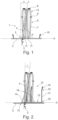
- Weitere Merkmale und Vorteile der Erfindung sind anhand schematisch gezeigter Ausführungsbeispiele näher erläutert. Im Einzelnen zeigt:
- Figur 1
- eine schematische Frontansicht auf ein Gurtgestell im angeordneten Zustand an einem Fahrzeugboden eines Fahrzeugs,
- Figur 2
- eine schematische Frontansicht auf eine weitere Ausführungsform eines Gurtgestells im angeordneten Zustand an einem Fahrzeugboden eines Fahrzeugs,
- Figur 3
- eine schematische, perspektivische Ansicht von seitlich, hinten oben auf eine weitere Ausführungsform eines Gurtgestells,
- Figur 4
- eine schematische Rückansicht auf das Gurtgestell gemäß
Figur 3 , - Figur 5
- eine schematische Seitenansicht auf das Gurtgestell gemäß
Figur 3 , - Figur 6
- eine schematische, perspektivische Ansicht von seitlich, hinten oben auf eine weitere Ausführungsform eines Gurtgestells,
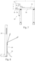
- Figur 7
- eine schematische Unteransicht auf das Gurtgestell gemäß
Figur 6 , - Figur 8
- eine schematische Seitenansicht auf das Gurtgestell gemäß
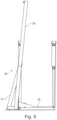
Figur 6 , - Figur 9
- eine schematische Rückansicht auf das Gurtgestell gemäß
Figur 6 , - Figur 10
- eine schematische, seitliche Teilansicht auf ein Gurtgestell mit einer Darstellung von möglichen Ausbildungsvarianten eines Stützelements am Gurtgestell und
- Figur 11
- eine schematische Frontansicht auf ein Gurtgestell mit zwei Vertikalstreben.
- Im Folgenden werden zum leichteren Verständnis für gleiche Elemente unterschiedlicher Ausführungsformen gleiche Bezugszeichen verwendet.
- In
Figur 1 ist ein Gurtgestell 1 gezeigt, welches an einem Fahrzeugboden 2 eines Fahrzeugs (nicht gezeigt) angeordnet und an einem Fahrzeugrahmen 3 des Fahrzeugs mittels Befestigungsmittel, z.B. in Form von Schrauben oder Nieten, befestigt ist. - Beispielsweise umfasst das Gurtgestell 1 eine Vertikalstrebe 4, welche an einem ersten Ende 5 am Fahrzeugboden 2 aufstehend angeordnet ist. Außerdem kann das Gurtgestell 1 ein Personenrückhaltesystem 6 aufweisen. Beispielweise umfasst das Personenrückhaltesystem 6 einen Sicherheitsgurt 7, eine Gurtumlenkanordnung 8, ein Gurtschloss 9, ein Schließelement 10 und/oder eine Gurtbefestigung 11.
- Beispielsweise ist an einem zweiten Ende 12 der Vertikalstrebe 4 die Gurtumlenkanordnung 8 befestigt. Zum Beispiel ist am Fahrzeugboden 2 das Schließelement 10 unmittelbar angeordnet.
- Beispielsweise erstreckt sich der Fahrzeugboden 2 in einer Fahrzeugbodenebene F und die Vertikalstrebe 4 entlang einer Längsachse L. Zum Beispiel schließen die Fahrzeugbodenebene F und die Längsachse L der Vertikalstrebe 4 einen Winkel β ein. Beispielsweise schließen die Normale des Fahrzeugbodens F und die Längsachse L der Vertikalstrebe 4 einen Winkel α ein.
- Das Gurtgestell 12 gemäß
Figur 2 unterscheidet sich vom Gurtgestell 1 gemäßFigur 1 darin, dass das Gurtgestell 12 neben der Vertikalstrebe 4 ein Anbringelement 13 aufweist. Beispielsweise ist das Anbringelement 13 in Form einer Platte ausgebildet. - Die Vertikalstrebe 4 ist aufstehend auf dem Anbringelement 13 vorhanden. Beispielsweise ist das Anbringelement 13 im angeordneten Zustand des Gurtgestells 12 am Fahrzeugboden 2 aufliegend vorhanden. Denkbar ist, dass im angeordneten Zustand des Gurtgestells 12 am Fahrzeugboden 2 das Anbringelement 13 mit dem Fahrzeugrahmen 3 über Befestigungsmittel verbunden ist. Vorstellbar ist außerdem, dass die Vertikalstrebe 4 mit dem Anbringelement 13 verbunden ist, sodass die Vertikalstrebe 4 über das Anbringelement 13 im angeordneten Zustand des Gurtgestells 12 am Fahrzeugboden 2 mit dem Fahrzeugrahmen 3 verbunden ist.
- Beispielsweise erstreckt sich das Anbringelement 13 in einer Anbringebene A. Zum Beispiel schließt die Längsachse L der Vertikalstrebe 4 mit der Anbringebene A eine Winkel ε ein. Beispielsweise schließen eine Normale der Anbringebene A und die Längsachse L der Vertikalstrebe 4 einen Winkel ϑ ein.
- Beispielsweise umfasst das Gurtgestell 12 ein Stützelement 14. Beispielsweise ist das Stützelement 14 mit einem ersten Ende 15 am Anbringelement 13 befestigt und mit einem zweiten Ende 16 an der Vertikalstrebe 4. Vorstellbar ist außerdem, dass am Anbringelement 13 ein Verlängerungselement 17 angeordnet ist. Beispielsweise ist das Verlängerungselement 17 in Form einer Gurtpeitsche vorhanden. Zum Beispiel ist das Verlängerungselement 17 mit einem ersten Ende 18 am Anbringelement 13 befestigt und von diesem mit einem zweiten Ende 19 abstehend vorhanden. Beispielsweise ist am zweiten Ende 19 des Verlängerungselements 17 ein Schließelement 10 ausgebildet.
- In
Figur 3 ist eine weitere Ausführungsform eines Gurtgestells 20 gezeigt. Beispielsweise umfasst das Gurtgestell 20 eine Vertikalstrebe 21, ein Anbringelement 22, Verlängerungselemente 23, ein erstes Stützelement 24 und/oder ein zweites Stützelement 25. - Beispielsweise ist das Anbringelement 22 gemäß
Figur 3 als ein abgekantetes Blechbiegeelement ausgebildet. Beispielsweise erstreckt sich das Anbringelement 22 in eine Länge l, eine Breite b und in eine Höhe h (siehe auchFiguren 4, 5 ). - Zum Beispiel ist am Gurtgestell 20 das zweite Stützelement 25 in Form eines Stützfuß ausgebildet, sodass das zweite Stützelement 25 die Vertikalstrebe 21 im Belastungsfall im angeordneten Zustand am Fahrzeug in eine Fahrtrichtung FR nach unten zum Fahrzeugboden abstützt. Beispielsweist umfasst das Gurtgestell 20 das erste Stützelement 24, welches die Vertikalstrebe 21 analog zum Stützelement 14 gemäß der Ausführung des Gurtgestells 12 seitlich abstützt.
- Beispielsweise sind am Anbringelement 22 des Gurtgestells 20 in vertikaler Richtung vom Anbringelement 22 abstehende Verlängerungselemente 23 angeordnet. Zum Beispiel sind die Verlängerungselemente 23 aus einer Metallstrebe 26 und einem daran angeordneten, z.B. flexiblem, Gurtband 27 gebildet, an dessen Ende ein Schließelement 10 angeordnet ist.
- In den
Figuren 6 bis 9 ist eine weitere Ausführungsform eines Gurtgestells 28 gezeigt. Beispielsweise umfasst das Gurtgestell 28 eine Vertikalstrebe 29, ein Anbringelement 30, ein erstes Stützelement 31, ein zweites Stützelement 32 und/oder ein Verlängerungselement 33. - In
Figur 7 ist gezeigt, dass am Anbringelement 30 Montageorgane 34 ausgebildet sind, um das Anbringelement 30 im angeordneten Zustand am Fahrzeug mit dem Fahrzeug zu verbinden. Beispielsweise sind die Montageorgane 34 in Form von Durchgangslöchern oder Bohrungen am Anbringelement 30 ausgebildet. - In
Figur 10 ist schematisch dargestellt, dass eine Vertikalstrebe 35 eines Gurtgestells 36 durch ein Stützelement 37, 38 entweder in Fahrtrichtung FA oder entgegen der Fahrtrichtung FA im angeordneten Zustand am Fahrzeug abstützbar ist. - In
Figur 11 ist eine weitere Ausführungsform eines Gurtgestells 39 gezeigt. Beispielsweise umfasst das Gurtgestell 39 zwei Vertikalstreben 40. Zum Beispiel sind die beiden Vertikalstreben 40 zueinander parallel ausgerichtet vorhanden. Denkbar ist, dass die Längsachsen der Vertikalstreben 40 zueinander parallel ausgerichtet vorhanden sind. Zum Beispiel umfasst das Gurtgestell 40 ein Anbringelement 41 und eine Horizontalstrebe 42. Beispielsweise ist die Horizontalstrebe 42 quer zur Längserstreckung der Vertikalstreben 409 ausgerichtet vorhanden. Beispielsweise ist an der Horizontalstrebe 42 ein Schließelement 10 angeordnet. - Beispielweise sind die Vertikalstreben 40 relativ zum Fahrzeugboden 2 oder zur Anbringebene A des Anbringelements 41 gekippt vorhanden, z.B. in die Bildebene nach hinten. Schematisch ist hierzu in
Figur 11 der Winkel γ der Längsachse L der Vertikalstrebe 40 relativ zur Längsachse der Horizontalstrebe 42 angedeutet.Bezugszeichenliste 1 Gurtgestell 37 Stützelement 2 Fahrzeugboden 38 Stützelement 3 Fahrzeugrahmen 39 Gurtgestell 4 Vertikalstrebe 40 Vertikalstrebe 5 Ende 41 Anbringelement 6 Personenrückhaltesystem 42 Horizontalstrebe 7 Sicherheitsgurt 8 Gurtumlenkanordnung 9 Gurtschloss 10 Schließelement 11 Gurtbefestigung 12 Gurtgestell 13 Anbringelement 14 Stützelement 15 Ende 16 Ende 17 Verlängerungselement 18 Ende 19 Ende 20 Gurtgestells 21 Vertikalstrebe 22 Anbringelement 23 Verlängerungselemente 24 Stützelement 25 Stützelement 26 Metallstrebe 27 Gurtband 28 Gurtgestell 29 Vertikalstrebe 30 Anbringelement 31 Stützelement 32 Stützelement 33 Verlängerungselement 34 Montageorgan 35 Vertikalstrebe 36 Gurtgestell
Claims (9)
- Gurtgestell (1, 12, 20, 28, 36, 39) für einen Fahrzeugsitz oder eine Fahrzeugsitzbank in einem Fahrzeug, wobei das Gurtgestell (1, 12, 20, 28, 36, 39) ein Anbringelement (13, 22, 30, 41), eine Vertikalstrebe (4, 21, 29, 35, 40) und ein Personenrückhaltesystem aufweist, wobei das Anbringelement (13, 22, 30, 41) dazu ausgebildet ist, an einer Fahrzeugstruktur des Fahrzeugs im Bereich eines Fahrzeugbodens (2) angeordnet zu werden, sodass das Gurtgestell (1, 12, 20, 28, 36, 39) im Bereich des Fahrzeugbodens (2) fixierbar ist, wobei die Vertikalstrebe (4, 21, 29, 35, 40) an einem ersten Ende (5) der Vertikalstrebe (4, 21, 29, 35, 40) mit dem Anbringelement (13, 22, 30, 41) verbunden ist, wobei die Vertikalstrebe (4, 21, 29, 35, 40) am ersten Ende (5) aufstehend auf dem Anbringelement vorhanden ist, wobei eine Längsachse der Vertikalstrebe (4, 21, 29, 35, 40) sich in Richtung der Vertikalen erstreckt, wobei ein Rückhalteorgan (10) des Personenrückhaltesystems (6) am Anbringelement (13, 22, 30, 41) befestigt ist, wobei das Anbringelement (13, 22, 30, 41) als eine Platte, als ein Winkelblech oder als eine Leiste ausgebildet ist, wobei das Personenrückhaltesystem einen Sicherheitsgurt, einen Gurtaufroller, ein Gurtumlenkelement, eine Gurtschließe und ein Gurtschloss aufweist, wobei das Gurtgestell (1, 12, 20, 28, 36, 39) eine Gurtpeitsche (17) aufweist, wobei das Gurtschloss des Personenrückhaltesystems über die Gurtpeitsche (17) mit dem Anbringelement (13, 22, 30, 41) verbunden ist, wobei die Gurtpeitsche in Form eines Gurtbands und/oder in Form eines Metallbands vorhanden ist, wobei das Gurtumlenkelement im Bereich eines zweiten Endes der Vertikalstrebe ausgebildet ist, wobei der Gurtaufroller am Anbringelement oder an der Vertikalstrebe befestigt ist.
- Gurtgestell (1, 12, 20, 28, 36, 39) nach einem der vorangegangenen Ansprüche, dadurch gekennzeichnet, dass der Sicherheitsgurt mit einem ersten Ende des Sicherheitsgurts mit dem Anbringelement verbunden ist, wobei der Sicherheitsgurt mit einem zweiten Ende des Sicherheitsgurts mit dem Gurtaufroller verbunden ist.
- Gurtgestell (1, 12, 20, 28, 36, 39) nach einem der vorangegangenen Ansprüche, dadurch gekennzeichnet, dass am Anbringelement (13, 22, 30, 41) ein Stützfuß (14, 24, 25) angeordnet ist.
- Gurtgestell (1, 12, 20, 28, 36, 39) nach einem der vorangegangenen Ansprüche, dadurch gekennzeichnet, dass das Anbringelement (13, 22, 30, 41) aus Metall ausgebildet ist.
- Gurtgestell (1, 12, 20, 28, 36, 39) nach einem der vorangegangenen Ansprüche, dadurch gekennzeichnet, dass die Vertikalstrebe (4, 21, 29, 35, 40) unlösbar mit dem Anbringelement (13, 22, 30, 41) verbunden ist.
- Gurtgestell (1, 12, 20, 28, 36, 39) nach einem der vorangegangenen Ansprüche, dadurch gekennzeichnet, dass am Anbringelement (13, 22, 30, 41) zwei oder mehr Rückhalteorgane (10) des Personenrückhaltesystems angeordnet sind.
- Gurtgestell (1, 12, 20, 28, 36, 39) nach einem der vorangegangenen Ansprüche, dadurch gekennzeichnet, dass am Anbringelement (13, 22, 30, 41) ein Montageorgan (34) ausgebildet ist, wobei das Montageorgan (34) dazu ausgebildet ist, im angeordneten Zustand des Gurtgestells (1, 12, 20, 28, 36, 39) am Fahrzeug das Anbringelement (13, 22, 30, 41) mit einer Fahrzeugstruktur eines Fahrzeugs zu verbinden.
- Fahrzeug-Sitzanordnung, wie ein Fahrzeugsitz oder eine Fahrzeugsitzbank, mit einem Gurtgestell (1, 12, 20, 28, 36, 39) nach einem der vorangegangen genannten Ansprüche.
- Fahrzeug mit einer Fahrzeug-Sitzanordnung nach dem vorangegangenen Anspruch 8 oder mit einem Gurtgestell (1, 12, 20, 28, 36, 39) nach einem der vorangegangenen Ansprüche 1 bis 7.
Applications Claiming Priority (1)
| Application Number | Priority Date | Filing Date | Title |
|---|---|---|---|
| DE102022102686.8A DE102022102686A1 (de) | 2022-02-04 | 2022-02-04 | Gurtgestell für einen Fahrzeugsitz |
Publications (2)
| Publication Number | Publication Date |
|---|---|
| EP4223596A1 EP4223596A1 (de) | 2023-08-09 |
| EP4223596B1 true EP4223596B1 (de) | 2025-06-11 |
Family
ID=85076086
Family Applications (1)
| Application Number | Title | Priority Date | Filing Date |
|---|---|---|---|
| EP23153313.4A Active EP4223596B1 (de) | 2022-02-04 | 2023-01-25 | Gurtgestell für einen fahrzeugsitz |
Country Status (2)
| Country | Link |
|---|---|
| EP (1) | EP4223596B1 (de) |
| DE (1) | DE102022102686A1 (de) |
Citations (2)
| Publication number | Priority date | Publication date | Assignee | Title |
|---|---|---|---|---|
| US5868452A (en) * | 1993-05-19 | 1999-02-09 | Aquti Produktentwicklung & Design Gmbh | Bench seat for motor vehicles, in particular camping cars |
| US20210078525A1 (en) * | 2019-09-18 | 2021-03-18 | Aguti Produktentwicklung & Design Gmbh | Device for arranging a passenger restraint system in a vehicle |
Family Cites Families (13)
| Publication number | Priority date | Publication date | Assignee | Title |
|---|---|---|---|---|
| US3885810A (en) | 1972-01-10 | 1975-05-27 | John J Chika | Seat supporting structure for fast moving vehicles |
| DE9308942U1 (de) * | 1993-05-19 | 1993-09-16 | Aguti Sitztechnik GmbH, 87719 Mindelheim | Sitzbank für Kraftfahrzeuge, insbesondere Wohnmobile |
| DE4324420A1 (de) | 1993-07-21 | 1995-01-26 | Dethleffs Gmbh | Wohnwagen mit einer Befestigungsvorrichtung für Sicherheitsgurte |
| DE20008510U1 (de) | 2000-05-11 | 2000-10-19 | Unex-Metall GmbH, 96194 Walsdorf | Einstellung zur Höhenverstellung eines Fahrzeug-Sicherheitsgurtes |
| DE102006007383B4 (de) | 2006-02-17 | 2008-04-30 | Unex-Metall Gmbh | Rückhaltesystem für eine Sitzbank im Wohnbereich eines Wohnmobils |
| US8628144B2 (en) * | 2011-01-31 | 2014-01-14 | Toyota Motor Engineering & Manufacturing North America, Inc. | Reinforcement assembly for reinforcing a seat belt apparatus of a seat assembly |
| DE102011015347B4 (de) * | 2011-03-28 | 2016-06-09 | Grammer Aktiengesellschaft | Gurtbefestigung am hinteren Hauptrohr der Tragstruktur, idealerweise am hinteren untenliegenden Fuß |
| CN102923030B (zh) * | 2012-11-22 | 2017-04-19 | 上海延锋江森座椅有限公司 | 一种汽车双人座座椅骨架 |
| DE102014003966A1 (de) | 2014-03-20 | 2015-09-24 | Aguti Produktentwicklung & Design Gmbh | Vorrichtung zur Anordnung eines Personenrückhaltesystems zur Sicherung von Personen in einem Verkehrsmittel und Verkehrsmittel |
| DE202016102135U1 (de) | 2016-04-22 | 2017-07-27 | Alois Kober Gmbh | Gurtbockanordnung |
| EP3321126B2 (de) | 2016-11-11 | 2025-06-11 | Aguti Produktentwicklung & Design Gmbh | Gurtgestell für einen fahrzeugsitz |
| DE102017105384A1 (de) | 2017-03-14 | 2018-09-20 | Aguti Produktentwicklung & Design Gmbh | Vorrichtung zur Anordnung eines Personenrückhaltesystems in einem Fahrzeug |
| DE102019206965B4 (de) * | 2019-05-14 | 2024-01-25 | Pössl Freizeit und Sport GmbH | Gurtsystem für ein Fahrzeug |
-
2022
- 2022-02-04 DE DE102022102686.8A patent/DE102022102686A1/de active Pending
-
2023
- 2023-01-25 EP EP23153313.4A patent/EP4223596B1/de active Active
Patent Citations (2)
| Publication number | Priority date | Publication date | Assignee | Title |
|---|---|---|---|---|
| US5868452A (en) * | 1993-05-19 | 1999-02-09 | Aquti Produktentwicklung & Design Gmbh | Bench seat for motor vehicles, in particular camping cars |
| US20210078525A1 (en) * | 2019-09-18 | 2021-03-18 | Aguti Produktentwicklung & Design Gmbh | Device for arranging a passenger restraint system in a vehicle |
Also Published As
| Publication number | Publication date |
|---|---|
| DE102022102686A1 (de) | 2023-08-10 |
| EP4223596A1 (de) | 2023-08-09 |
Similar Documents
| Publication | Publication Date | Title |
|---|---|---|
| EP3964405B1 (de) | Lasttragendes strukturteil für einen fahrzeugsitz | |
| EP0765252B1 (de) | Sitzbank für kraftfahrzeuge, insbesondere wohnmobile | |
| EP4144597B1 (de) | Fahrzeugsitzstruktur sowie verfahren zur montage einer fahrzeugsitzstruktur | |
| DE102010051325A1 (de) | Sitzfuß für einen Personensitz | |
| DE102007046958A1 (de) | Energieabsorptions-Sitzverankerungs-Rückhaltesystem für Kinder-Sicherheitssitze | |
| DE19800072A1 (de) | Rückhaltesystem für einen in einem Kraftfahrzeug mitgeführten Kindersitz | |
| EP3539818B1 (de) | Gurtgestell für einen fahrzeugsitz oder eine fahrzeugsitzbank und fahrzeug-sitzanordnung | |
| EP3508373B2 (de) | Gurtgestell für einen fahrzeugsitz | |
| DE19901784A1 (de) | Sicherheitsrückhaltesystem | |
| EP4098482A1 (de) | Gurtgestell und fahrzeugsitz | |
| EP3398840B1 (de) | Vorrichtung zur anordnung eines personenrückhaltesystems in einem fahrzeug | |
| EP4223596B1 (de) | Gurtgestell für einen fahrzeugsitz | |
| EP3366511B1 (de) | Gurtgestell für einen fahrzeugsitz oder eine fahrzeugsitzbank | |
| EP3375659B1 (de) | Vorrichtung zur anordnung eines personenrückhaltesystems in einem fahrzeug | |
| EP4223595A1 (de) | Gurtgestell für einen fahrzeugsitz | |
| DE19758497C2 (de) | Energieabsorber für ein Rückhaltesystem in Fahrzeugen, Zügen und Flugzeugen | |
| DE102005057518B3 (de) | Verstärkungsstruktur eines Dreipunkt-Sicherheitsgurtes | |
| EP1783010B1 (de) | Abnehmbare Sicherheitsgurt-Befestigung | |
| DE10358425B4 (de) | Längenvariable Befestigungsvorrichtung | |
| DE202017007028U1 (de) | Gurtgestell für einen Fahrzeugsitz | |
| EP4349666A1 (de) | Gurtgestell für einen fahrzeugsitz | |
| DE102025143645A1 (de) | Rückenlehne mit integriertem Gurtretraktor und Fahrzeugsitz | |
| DE102024131483A1 (de) | Kraftfahrzeug | |
| WO2015110383A1 (de) | Gurtstraffereinheit für eine fahrzeug-sicherheitsgurtanordnung | |
| DE10257957A1 (de) | Hinteres Rückhaltesystem an Kraftfahrzeugen |
Legal Events
| Date | Code | Title | Description |
|---|---|---|---|
| PUAI | Public reference made under article 153(3) epc to a published international application that has entered the european phase |
Free format text: ORIGINAL CODE: 0009012 |
|
| STAA | Information on the status of an ep patent application or granted ep patent |
Free format text: STATUS: THE APPLICATION HAS BEEN PUBLISHED |
|
| AK | Designated contracting states |
Kind code of ref document: A1 Designated state(s): AL AT BE BG CH CY CZ DE DK EE ES FI FR GB GR HR HU IE IS IT LI LT LU LV MC ME MK MT NL NO PL PT RO RS SE SI SK SM TR |
|
| STAA | Information on the status of an ep patent application or granted ep patent |
Free format text: STATUS: REQUEST FOR EXAMINATION WAS MADE |
|
| 17P | Request for examination filed |
Effective date: 20231011 |
|
| RBV | Designated contracting states (corrected) |
Designated state(s): AL AT BE BG CH CY CZ DE DK EE ES FI FR GB GR HR HU IE IS IT LI LT LU LV MC ME MK MT NL NO PL PT RO RS SE SI SK SM TR |
|
| TPAC | Observations filed by third parties |
Free format text: ORIGINAL CODE: EPIDOSNTIPA |
|
| STAA | Information on the status of an ep patent application or granted ep patent |
Free format text: STATUS: EXAMINATION IS IN PROGRESS |
|
| 17Q | First examination report despatched |
Effective date: 20240402 |
|
| GRAP | Despatch of communication of intention to grant a patent |
Free format text: ORIGINAL CODE: EPIDOSNIGR1 |
|
| STAA | Information on the status of an ep patent application or granted ep patent |
Free format text: STATUS: GRANT OF PATENT IS INTENDED |
|
| INTG | Intention to grant announced |
Effective date: 20241120 |
|
| GRAJ | Information related to disapproval of communication of intention to grant by the applicant or resumption of examination proceedings by the epo deleted |
Free format text: ORIGINAL CODE: EPIDOSDIGR1 |
|
| STAA | Information on the status of an ep patent application or granted ep patent |
Free format text: STATUS: EXAMINATION IS IN PROGRESS |
|
| GRAP | Despatch of communication of intention to grant a patent |
Free format text: ORIGINAL CODE: EPIDOSNIGR1 |
|
| STAA | Information on the status of an ep patent application or granted ep patent |
Free format text: STATUS: GRANT OF PATENT IS INTENDED |
|
| INTC | Intention to grant announced (deleted) | ||
| INTG | Intention to grant announced |
Effective date: 20250212 |
|
| GRAS | Grant fee paid |
Free format text: ORIGINAL CODE: EPIDOSNIGR3 |
|
| GRAA | (expected) grant |
Free format text: ORIGINAL CODE: 0009210 |
|
| STAA | Information on the status of an ep patent application or granted ep patent |
Free format text: STATUS: THE PATENT HAS BEEN GRANTED |
|
| AK | Designated contracting states |
Kind code of ref document: B1 Designated state(s): AL AT BE BG CH CY CZ DE DK EE ES FI FR GB GR HR HU IE IS IT LI LT LU LV MC ME MK MT NL NO PL PT RO RS SE SI SK SM TR |
|
| REG | Reference to a national code |
Ref country code: GB Ref legal event code: FG4D Free format text: NOT ENGLISH |
|
| REG | Reference to a national code |
Ref country code: CH Ref legal event code: EP |
|
| REG | Reference to a national code |
Ref country code: DE Ref legal event code: R096 Ref document number: 502023001110 Country of ref document: DE |
|
| REG | Reference to a national code |
Ref country code: IE Ref legal event code: FG4D Free format text: LANGUAGE OF EP DOCUMENT: GERMAN |
|
| PG25 | Lapsed in a contracting state [announced via postgrant information from national office to epo] |
Ref country code: FI Free format text: LAPSE BECAUSE OF FAILURE TO SUBMIT A TRANSLATION OF THE DESCRIPTION OR TO PAY THE FEE WITHIN THE PRESCRIBED TIME-LIMIT Effective date: 20250611 Ref country code: ES Free format text: LAPSE BECAUSE OF FAILURE TO SUBMIT A TRANSLATION OF THE DESCRIPTION OR TO PAY THE FEE WITHIN THE PRESCRIBED TIME-LIMIT Effective date: 20250611 |
|
| REG | Reference to a national code |
Ref country code: LT Ref legal event code: MG9D |
|
| PG25 | Lapsed in a contracting state [announced via postgrant information from national office to epo] |
Ref country code: GR Free format text: LAPSE BECAUSE OF FAILURE TO SUBMIT A TRANSLATION OF THE DESCRIPTION OR TO PAY THE FEE WITHIN THE PRESCRIBED TIME-LIMIT Effective date: 20250912 Ref country code: NO Free format text: LAPSE BECAUSE OF FAILURE TO SUBMIT A TRANSLATION OF THE DESCRIPTION OR TO PAY THE FEE WITHIN THE PRESCRIBED TIME-LIMIT Effective date: 20250911 |
|
| REG | Reference to a national code |
Ref country code: NL Ref legal event code: MP Effective date: 20250611 |
|
| PG25 | Lapsed in a contracting state [announced via postgrant information from national office to epo] |
Ref country code: BG Free format text: LAPSE BECAUSE OF FAILURE TO SUBMIT A TRANSLATION OF THE DESCRIPTION OR TO PAY THE FEE WITHIN THE PRESCRIBED TIME-LIMIT Effective date: 20250611 |
|
| PG25 | Lapsed in a contracting state [announced via postgrant information from national office to epo] |
Ref country code: HR Free format text: LAPSE BECAUSE OF FAILURE TO SUBMIT A TRANSLATION OF THE DESCRIPTION OR TO PAY THE FEE WITHIN THE PRESCRIBED TIME-LIMIT Effective date: 20250611 |
|
| PG25 | Lapsed in a contracting state [announced via postgrant information from national office to epo] |
Ref country code: RS Free format text: LAPSE BECAUSE OF FAILURE TO SUBMIT A TRANSLATION OF THE DESCRIPTION OR TO PAY THE FEE WITHIN THE PRESCRIBED TIME-LIMIT Effective date: 20250911 |
|
| PG25 | Lapsed in a contracting state [announced via postgrant information from national office to epo] |
Ref country code: LV Free format text: LAPSE BECAUSE OF FAILURE TO SUBMIT A TRANSLATION OF THE DESCRIPTION OR TO PAY THE FEE WITHIN THE PRESCRIBED TIME-LIMIT Effective date: 20250611 |
|
| PG25 | Lapsed in a contracting state [announced via postgrant information from national office to epo] |
Ref country code: NL Free format text: LAPSE BECAUSE OF FAILURE TO SUBMIT A TRANSLATION OF THE DESCRIPTION OR TO PAY THE FEE WITHIN THE PRESCRIBED TIME-LIMIT Effective date: 20250611 |
|
| PG25 | Lapsed in a contracting state [announced via postgrant information from national office to epo] |
Ref country code: PT Free format text: LAPSE BECAUSE OF FAILURE TO SUBMIT A TRANSLATION OF THE DESCRIPTION OR TO PAY THE FEE WITHIN THE PRESCRIBED TIME-LIMIT Effective date: 20251013 |
|
| PG25 | Lapsed in a contracting state [announced via postgrant information from national office to epo] |
Ref country code: IS Free format text: LAPSE BECAUSE OF FAILURE TO SUBMIT A TRANSLATION OF THE DESCRIPTION OR TO PAY THE FEE WITHIN THE PRESCRIBED TIME-LIMIT Effective date: 20251011 |
|
| PG25 | Lapsed in a contracting state [announced via postgrant information from national office to epo] |
Ref country code: SM Free format text: LAPSE BECAUSE OF FAILURE TO SUBMIT A TRANSLATION OF THE DESCRIPTION OR TO PAY THE FEE WITHIN THE PRESCRIBED TIME-LIMIT Effective date: 20250611 |
|
| PG25 | Lapsed in a contracting state [announced via postgrant information from national office to epo] |
Ref country code: CZ Free format text: LAPSE BECAUSE OF FAILURE TO SUBMIT A TRANSLATION OF THE DESCRIPTION OR TO PAY THE FEE WITHIN THE PRESCRIBED TIME-LIMIT Effective date: 20250611 |
|
| PG25 | Lapsed in a contracting state [announced via postgrant information from national office to epo] |
Ref country code: PL Free format text: LAPSE BECAUSE OF FAILURE TO SUBMIT A TRANSLATION OF THE DESCRIPTION OR TO PAY THE FEE WITHIN THE PRESCRIBED TIME-LIMIT Effective date: 20250611 |
|
| PG25 | Lapsed in a contracting state [announced via postgrant information from national office to epo] |
Ref country code: EE Free format text: LAPSE BECAUSE OF FAILURE TO SUBMIT A TRANSLATION OF THE DESCRIPTION OR TO PAY THE FEE WITHIN THE PRESCRIBED TIME-LIMIT Effective date: 20250611 |
|
| PG25 | Lapsed in a contracting state [announced via postgrant information from national office to epo] |
Ref country code: SK Free format text: LAPSE BECAUSE OF FAILURE TO SUBMIT A TRANSLATION OF THE DESCRIPTION OR TO PAY THE FEE WITHIN THE PRESCRIBED TIME-LIMIT Effective date: 20250611 |
|
| REG | Reference to a national code |
Ref country code: DE Ref legal event code: R097 Ref document number: 502023001110 Country of ref document: DE |
|
| PG25 | Lapsed in a contracting state [announced via postgrant information from national office to epo] |
Ref country code: DK Free format text: LAPSE BECAUSE OF FAILURE TO SUBMIT A TRANSLATION OF THE DESCRIPTION OR TO PAY THE FEE WITHIN THE PRESCRIBED TIME-LIMIT Effective date: 20250611 |
|
| PGFP | Annual fee paid to national office [announced via postgrant information from national office to epo] |
Ref country code: DE Payment date: 20260120 Year of fee payment: 4 |
|
| PGFP | Annual fee paid to national office [announced via postgrant information from national office to epo] |
Ref country code: AT Payment date: 20260301 Year of fee payment: 4 |
|
| PGFP | Annual fee paid to national office [announced via postgrant information from national office to epo] |
Ref country code: IT Payment date: 20260131 Year of fee payment: 4 |
|
| PLBE | No opposition filed within time limit |
Free format text: ORIGINAL CODE: 0009261 |
|
| STAA | Information on the status of an ep patent application or granted ep patent |
Free format text: STATUS: NO OPPOSITION FILED WITHIN TIME LIMIT |
|
| PGFP | Annual fee paid to national office [announced via postgrant information from national office to epo] |
Ref country code: FR Payment date: 20260121 Year of fee payment: 4 |
|
| REG | Reference to a national code |
Ref country code: CH Ref legal event code: L10 Free format text: ST27 STATUS EVENT CODE: U-0-0-L10-L00 (AS PROVIDED BY THE NATIONAL OFFICE) Effective date: 20260423 |