EP4223686A2 - Deckverlängerungsmodul und system zur installation einer windturbine auf einer offshore-unterkonstruktion - Google Patents
Deckverlängerungsmodul und system zur installation einer windturbine auf einer offshore-unterkonstruktion Download PDFInfo
- Publication number
- EP4223686A2 EP4223686A2 EP23164613.4A EP23164613A EP4223686A2 EP 4223686 A2 EP4223686 A2 EP 4223686A2 EP 23164613 A EP23164613 A EP 23164613A EP 4223686 A2 EP4223686 A2 EP 4223686A2
- Authority
- EP
- European Patent Office
- Prior art keywords
- wind turbine
- tower
- crane
- clamp
- deck
- Prior art date
- Legal status (The legal status is an assumption and is not a legal conclusion. Google has not performed a legal analysis and makes no representation as to the accuracy of the status listed.)
- Pending
Links
Images





Classifications
-
- B—PERFORMING OPERATIONS; TRANSPORTING
- B66—HOISTING; LIFTING; HAULING
- B66C—CRANES; LOAD-ENGAGING ELEMENTS OR DEVICES FOR CRANES, CAPSTANS, WINCHES, OR TACKLES
- B66C1/00—Load-engaging elements or devices attached to lifting or lowering gear of cranes or adapted for connection therewith for transmitting lifting forces to articles or groups of articles
- B66C1/10—Load-engaging elements or devices attached to lifting or lowering gear of cranes or adapted for connection therewith for transmitting lifting forces to articles or groups of articles by mechanical means
- B66C1/108—Load-engaging elements or devices attached to lifting or lowering gear of cranes or adapted for connection therewith for transmitting lifting forces to articles or groups of articles by mechanical means for lifting parts of wind turbines
-
- B—PERFORMING OPERATIONS; TRANSPORTING
- B66—HOISTING; LIFTING; HAULING
- B66C—CRANES; LOAD-ENGAGING ELEMENTS OR DEVICES FOR CRANES, CAPSTANS, WINCHES, OR TACKLES
- B66C23/00—Cranes comprising essentially a beam, boom, or triangular structure acting as a cantilever and mounted for translatory of swinging movements in vertical or horizontal planes or a combination of such movements, e.g. jib-cranes, derricks, tower cranes
- B66C23/18—Cranes comprising essentially a beam, boom, or triangular structure acting as a cantilever and mounted for translatory of swinging movements in vertical or horizontal planes or a combination of such movements, e.g. jib-cranes, derricks, tower cranes specially adapted for use in particular purposes
- B66C23/36—Cranes comprising essentially a beam, boom, or triangular structure acting as a cantilever and mounted for translatory of swinging movements in vertical or horizontal planes or a combination of such movements, e.g. jib-cranes, derricks, tower cranes specially adapted for use in particular purposes mounted on road or rail vehicles; Manually-movable jib-cranes for use in workshops; Floating cranes
- B66C23/52—Floating cranes
-
- F—MECHANICAL ENGINEERING; LIGHTING; HEATING; WEAPONS; BLASTING
- F03—MACHINES OR ENGINES FOR LIQUIDS; WIND, SPRING, OR WEIGHT MOTORS; PRODUCING MECHANICAL POWER OR A REACTIVE PROPULSIVE THRUST, NOT OTHERWISE PROVIDED FOR
- F03D—WIND MOTORS
- F03D13/00—Assembly, mounting or commissioning of wind motors; Arrangements specially adapted for transporting wind motor components
- F03D13/10—Assembly of wind motors; Arrangements for erecting wind motors
-
- F—MECHANICAL ENGINEERING; LIGHTING; HEATING; WEAPONS; BLASTING
- F03—MACHINES OR ENGINES FOR LIQUIDS; WIND, SPRING, OR WEIGHT MOTORS; PRODUCING MECHANICAL POWER OR A REACTIVE PROPULSIVE THRUST, NOT OTHERWISE PROVIDED FOR
- F03D—WIND MOTORS
- F03D13/00—Assembly, mounting or commissioning of wind motors; Arrangements specially adapted for transporting wind motor components
- F03D13/10—Assembly of wind motors; Arrangements for erecting wind motors
- F03D13/139—Assembling or erecting wind motors by using lifting means
-
- F—MECHANICAL ENGINEERING; LIGHTING; HEATING; WEAPONS; BLASTING
- F03—MACHINES OR ENGINES FOR LIQUIDS; WIND, SPRING, OR WEIGHT MOTORS; PRODUCING MECHANICAL POWER OR A REACTIVE PROPULSIVE THRUST, NOT OTHERWISE PROVIDED FOR
- F03D—WIND MOTORS
- F03D13/00—Assembly, mounting or commissioning of wind motors; Arrangements specially adapted for transporting wind motor components
- F03D13/20—Arrangements for mounting or supporting wind motors; Masts or towers for wind motors
- F03D13/25—Arrangements for mounting or supporting wind motors; Masts or towers for wind motors specially adapted for offshore installation
-
- F—MECHANICAL ENGINEERING; LIGHTING; HEATING; WEAPONS; BLASTING
- F05—INDEXING SCHEMES RELATING TO ENGINES OR PUMPS IN VARIOUS SUBCLASSES OF CLASSES F01-F04
- F05B—INDEXING SCHEME RELATING TO WIND, SPRING, WEIGHT, INERTIA OR LIKE MOTORS, TO MACHINES OR ENGINES FOR LIQUIDS COVERED BY SUBCLASSES F03B, F03D AND F03G
- F05B2230/00—Manufacture
- F05B2230/60—Assembly methods
- F05B2230/61—Assembly methods using auxiliary equipment for lifting or holding
- F05B2230/6102—Assembly methods using auxiliary equipment for lifting or holding carried on a floating platform
-
- Y—GENERAL TAGGING OF NEW TECHNOLOGICAL DEVELOPMENTS; GENERAL TAGGING OF CROSS-SECTIONAL TECHNOLOGIES SPANNING OVER SEVERAL SECTIONS OF THE IPC; TECHNICAL SUBJECTS COVERED BY FORMER USPC CROSS-REFERENCE ART COLLECTIONS [XRACs] AND DIGESTS
- Y02—TECHNOLOGIES OR APPLICATIONS FOR MITIGATION OR ADAPTATION AGAINST CLIMATE CHANGE
- Y02E—REDUCTION OF GREENHOUSE GAS [GHG] EMISSIONS, RELATED TO ENERGY GENERATION, TRANSMISSION OR DISTRIBUTION
- Y02E10/00—Energy generation through renewable energy sources
- Y02E10/70—Wind energy
- Y02E10/72—Wind turbines with rotation axis in wind direction
-
- Y—GENERAL TAGGING OF NEW TECHNOLOGICAL DEVELOPMENTS; GENERAL TAGGING OF CROSS-SECTIONAL TECHNOLOGIES SPANNING OVER SEVERAL SECTIONS OF THE IPC; TECHNICAL SUBJECTS COVERED BY FORMER USPC CROSS-REFERENCE ART COLLECTIONS [XRACs] AND DIGESTS
- Y02—TECHNOLOGIES OR APPLICATIONS FOR MITIGATION OR ADAPTATION AGAINST CLIMATE CHANGE
- Y02E—REDUCTION OF GREENHOUSE GAS [GHG] EMISSIONS, RELATED TO ENERGY GENERATION, TRANSMISSION OR DISTRIBUTION
- Y02E10/00—Energy generation through renewable energy sources
- Y02E10/70—Wind energy
- Y02E10/727—Offshore wind turbines
-
- Y—GENERAL TAGGING OF NEW TECHNOLOGICAL DEVELOPMENTS; GENERAL TAGGING OF CROSS-SECTIONAL TECHNOLOGIES SPANNING OVER SEVERAL SECTIONS OF THE IPC; TECHNICAL SUBJECTS COVERED BY FORMER USPC CROSS-REFERENCE ART COLLECTIONS [XRACs] AND DIGESTS
- Y02—TECHNOLOGIES OR APPLICATIONS FOR MITIGATION OR ADAPTATION AGAINST CLIMATE CHANGE
- Y02P—CLIMATE CHANGE MITIGATION TECHNOLOGIES IN THE PRODUCTION OR PROCESSING OF GOODS
- Y02P70/00—Climate change mitigation technologies in the production process for final industrial or consumer products
- Y02P70/50—Manufacturing or production processes characterised by the final manufactured product
Definitions
- the present invention relates to a deck extension module for the installation of a wind turbine on an offshore substructure.
- the present invention relates also to a system and method making use of the deck extension module for the installation of a wind turbine on an offshore substructure.
- wind turbine identifies a wind turbine including a tower; a nacelle mounted atop the tower; and a rotor fitted to the nacelle including a hub and a complete set of blades.
- the definition "tower” identifies an elongated vertical structure; the definition “nacelle” identifies a structure housing an electric generator and configured to be mounted atop the tower in a rotatable manner about the axis of the tower.
- the definition “rotor” identifies an assembly comprising a hub to be fitted in rotatable manner to the nacelle.
- offshore substructure identifies support structure and foundations to transfer loads to the bed of a body of water.
- the current trend regarding the offshore wind turbine continues to look at increasing the electric power output of wind turbine and calls for increasing the size of the wind turbines.
- the so-called high-power wind turbines currently under test may reach the size of the rotor diameter of 240 m.
- Offshore wind farms require transporting the wind turbines to installation sites by means of vessels and installing them on respective offshore substructures. These operations are complex and the complexity increases with the size of the wind turbines.
- document EP 2,275,340 A2 discloses an installation jack-up vessel provided with a cantilever mast used to transfer of wind turbine components from the deck of the jack-up vessel to an offshore installation site and guide the transfer to prevent undesired swinging movements of the wind turbine components.
- a main crane is used in cooperation with a guide arm to transfer and guide wind turbine components from the jack-up vessel to the offshore installation site.
- Document GB 2,423,108 discloses installing a wind turbine by means of a vessel in an offshore substructure provided with a foundation in the bottom of the body of water and a socket for housing the wind turbine.
- the vessel is configured to transfer the wind turbine in a reclined position on the deck of the vessel and comprises an A-frame operated by winches to erect the wind turbine above the substructure and nest the wind turbine in the socket.
- One object of the present invention is to provide a deck extension module for the installation of a wind turbine on an offshore substructure in a safe and straightforward manner even in deep water.
- Another object of the present invention is to configure a system for the installation of a wind turbine on an offshore substructure in a safe and straightforward manner even in deep water.
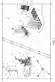
- Number 1 in Figure 1 indicates a system for installing wind turbines 2 on offshore substructures 3.
- the installation of wind turbines 2 includes:
- the system 1 comprises:
- the wind turbine 2 comprises a tower 12 extending along a longitudinal axis A1; a nacelle 13 rotatably mounted atop the tower 12; and a rotor 14 rotatably mounted to the nacelle 13.
- the rotor 14 further comprising a hub 15 and blades 16 radially extending from the hub 15.
- the onshore construction site 4 delivers towers 12, blades 16 and subassemblies 17 including, each, one nacelle 13 and one hub 15.
- a number of towers 12, blades 16 and subassemblies 17 is supplied to the crane vessel 5 by a carrier vessel 18.
- the crane vessel 5 comprises a main deck 19 for temporarily storing a number of towers 12, blades 16 and subassemblies 17, which are transferred from the transfer vessel 18 on the main deck 19 by means of one lifting crane 6.
- Blades 16 are located in a blade rack 20 for safe support and transport.
- Each wind turbine 2 is assembled on the crane vessel 5 and, in particular, on the deck extension module 10, which is mounted on the crane vessel 5.
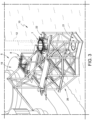
- the deck extension module 10 comprises a lower deck 21 defining a passive constraint for a tower 12 ( Figure 3 ) in an upright position; and an upper deck 22 for hosting the multi-functional clamp 7, which defines an active constraint for the same tower 12 ( Figure 3 ).
- the deck extension module 10 comprises a top structure 23 elevated from the upper deck 22 for supporting the stability frame 8 ( Figure 3 ).
- the lower deck 21 comprises a pit 24, which is sized to constrain the bottom end of the tower 12 ( Figure 3 ).
- the upper deck 22 is U-shaped and comprises protrusions 25 ( Figure 2 ) for cooperation with the multi-functional clamp 7 ( Figure 3 ) so as to locate the multi-functional clamp 7 in a given position.
- the deck extension module 10 comprises a lattice structure 26 for supporting the lower deck 21, the upper deck 22 and the top structure 23 for releasable connection with the crane vessel 5.
- the upper deck 22 is the same level the main deck 19.
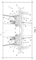
- the multi-functional clamp 7 comprises a main body 27, which is configured to be arranged about the lower part of the tower 12 and is shaped so as to shape-couple with protrusions 25 ( Figure 2 ) of the deck extension module 10 and so as to constrain the multi-functional clamp 7 along the upper deck 22.
- the protrusion 25 ( Figure 2 ) are cylindrical and the main body 27 is provided with recesses, in particular holes 28 ( Figure 5 ), more in particular blind holes, for housing the protrusions 25 so as to constrain the movement of the multi-functional clamp 7 transversely to the upper deck 22 and allowing free movement perpendicularly to the upper deck 22.
- the multi-functional clamp 7 comprises a plurality of jaws 29, which extend inwardly from the main body 27 and are moveable between extended positions and retracted positions for respectively clamping and releasing the tower 12; and actuators 30 for controlling jaws 28.
- the multi-functional clamp 7 comprises a plurality of hooking members 31 extending from the main body 27 and configured to secure the ends of the rigging assembly 11 of a crane 6 to the multi-functional clamp 7 ( Figure 6 ).
- Each hooking member 31 comprises two flanges 32 having respective aligned holes; and a pin configured to insert in both holes, and controlled by an actuator 33 mounted on one of said flanges 28.
- the main body 27 is annular, openable in an open configuration ( Figure 4 ), and closable in a close configuration ( figure 5 ).
- the main body 27 comprises three sector 34, 35, and 36, wherein sectors 35 and 36 are hinged to sector 34 on the opposite sides of the latter and are connectable to each other in a close position.
- the multi-functional clamp 7 comprises actuators 37 for controlling the position of sectors 35 and 36 with respect to sector 34, and actuators 38 to lock sectors 33 and 34 in the closed position by latching them one another.
- the rigging assembly 11 comprises two riggings 39 each one operated by a respective lifting crane 6 ( Figure 1 ).
- Each rigging 39 comprises one upper block 40 for connection to lifting crane 6 ( Figure 1 ); a double sling 41; a further block 42; two slings 43 for connections of block 42 to a spreader bar 44; and two hoisting lines 45.
- Each hoisting line 45 is suspended to the spreader bar 44 and has eyelets 46 at its distal ends to be anchored to respective hooking member 31 of the multi-functional clamp 7.
- Each hoisting line 45 comprises an elongated flexible rope and an intermediate rigid section 47, which is a bar or a tube, is connected to rope, and is configured to cooperate, in use, with the stability frame 8. Namely, the rigid sections 47 are inserted into the stability frame 8, when in use, by rotation of lifting cranes 6 ( Figure 1 ) according to arrows F.
- the stability frame 8 comprises a U-shaped main body 48 configured to be mounted, in use, about the tower 12; a clamp assembly 49 mounted on the main body 48 for selectively anchoring and releasing the main body 48 about the tower 12 of the wind turbine 2.
- the stability frame 8 comprises a plurality of guides 50, which extend outwardly from the main body 48 and are configured to guide and housing parts of the riggings 39, in particular, the rigid sections 47 of the riggings 39 ( Figure 6 ).
- Each guide 50 comprises two bars 51 provided with flared free ends in order to facilitate the insertion of the riggings 39 ( Figure 2 ) into the guides 50.
- the stability frame 8 comprises four guides 50 arranged two by two along opposite sides of the main body 48.
- the clamp assembly 49 comprises two idle jaws 52, which are mounted to the main body 48 and extends inwardly from the main body 48, and two actuated jaws 53, which are configured to be actuated between retracted positions and inwardly projecting positions towards the idle jaws 52 by actuators 54.
- one idle jaw is sufficient to anchor the stability frame 8 to the tower 12.
- the stability frame 8 comprises two actuators 54 for each actuated jaw 53.
- actuators 54 of each actuated jaw 53 are operated in parallel and are designed to operate singly in case of failure of one of said two actuators 54.
- Each actuated jaw 53 is articulated to an A-shaped frame 55, which, in turn, is articulated to the main body 48 and each actuators 54 is articulated to the A-shaped frame 55 and the main body 48.
- the stability frame 8 is provided with supporting legs 56 and is displaced by means of the lifting cranes 6 and, for this purpose, is provided with two hooking members 57 mounted on the main body 48 for connection of the stability frame 8 to the lifting cranes 6 ( Figure 1 ).
- the stability frame 8 comprises two attachments 58 for tugger lines 59 operated from winches, not shown, of the dual crane vessel 5 ( Figure 8 ).
- the actuators 30, 33, 37 and 38 of the multi-functional clamp 7 ( Figure 4 ) and the actuators 54 of the stability frame 8 ( Figure 7 ) are hydraulic cylinders.
- the multi-functional clamp 7 and the stability frame 8 can be displaced by the lifting cranes 6 ( Figure 8 ) and the system 1 is configured to control the actuators 30, 33, 37 and 38 of the multi-functional clamp 7 ( Figure 4 ) and the actuators 54 of the stability frame 8 ( Figure 7 ) in any position they can assume during use.
- the system 1 is configured to control the multi-functional clamp 7 and the stability frame 8 from a remote position and for this purpose comprises a hydraulic circuit and a control system that, partly, extend along the stability frame 8, partly, along the multi-functional clamp 7 and, partly, on the crane vessel 5.
- the hydraulic circuit comprises a first portion located in the crane vessel 5; a second portion mounted on the multi-functional clamp 7, and a portion mounted on the stability frame 8; and umbilicals 60 for selectively connecting the first portion to the second portion and the fist portion to the third portion.
- the system 1 comprises further winches, not shown, on the crane vessel 5 for operating tugger lines 61 configured to be connected to the multi-functional clamp 7.
- the blade stability frame 9 is an extendable articulated frame, which is configured to be installed on a crane boom 62 for guiding the rigging assembly 11 when lifting a blade 16 and for supporting sheaves 63 for tugger lines 64 for controlling the position of the blade 16 during installation of the same and controlled by winches, not shown, on the crane vessel 5.
- the blade stability frame 9 is shown in a partially contracted configuration.
- the blade stability frame 9 comprises hinged beams 65, i.e. steel box sections connected by hinges, and a mechanism used to extend and retract the blade stability frame 9 comprising electric motors, not shown, for driving rack and pinion systems along a track on the box sections.
- the blade stability frame 9 is mounted onto the crane boom 62 via clamps or padeyes, not shown, on the boom 62, by using the first lifting crane 6 at the boom rest and the second lifting crane 6 working, facilitating a rapid installation in to the lifting crane 6, removal for rapid reconfiguration of the lifting vessel 5.
- the carrier vessel 18 transports a number of towers 12, subassemblies 17 and blades 16 from the onshore construction site 4 to the crane vessel 5 that is located in or in proximity of the offshore substructures 3.
- the towers 12, subassemblies 17 and blades 16 are transferred from the carrier vessel 18 to the main deck 19 of the crane vessel 5 by means of a lifting crane 6 and one tower 12 is located on the deck extension module 10 by means of a lifting crane 6.
- the bottom end of the tower 12 rest in the pit 24 of the lower deck 21 and is clamped by the multi-functional clamp 7 which is supported by the upper deck 22 in axial alignment with the pit 24.
- the lifting crane 6 release the tower 12 and lifts the subassembly 17 from the main deck 19 above the top end of the tower 12, and lowers the subassembly 17 atop the tower 12 for connection of the same.
- the lifting crane 6 lifts one blade 16 from the main deck 19 to a blade connection flange of the hub 15.
- the position of the blade 16 is controlled by the lifting crane 6 in combination with tugger lines 64 guided by the sheaves 63 mounted on the blade stability frame 9.
- the lifting crane 6 lifts the stability frame 8, which is brought about the tower 12 and is clamped to the tower 12 in proximity of the top of the same.
- the lifting crane 6 equipped with the rigging assembly 11 brings the hoisting lines 45 into the guides 50 of the stability frame 8 and the eyelet 46 at the hooking members 31 of the multi-functional clamp 7.
- the hooking members 31 secured the eyelets 46 to the multi-functional clamp 7.
- the lifting crane 6 lifts the wind turbine 2 and transfers it to the offshore substructure 3. Once the wind turbines is assembled to the offshore substructure 3, actuators 38 unlock the multi-functional clamp 7, and actuators 37 open the multi-functional clamp 7.
- Lifting crane 6 frees the hoisting lines 45 from the guides 50 of the stability frame 8 and brings the multi-functional clamp 7 on the upper deck 22 in the given position and in the open configuration for receiving one more tower 12.
- the lifting cranes 6 are secured to the stability frame 8, which is, then, unclamped from the tower 12 of the installed wind turbine 2 and is brought on the top structure 23 of the deck extension module 10.
Landscapes
- Engineering & Computer Science (AREA)
- Mechanical Engineering (AREA)
- Life Sciences & Earth Sciences (AREA)
- Sustainable Development (AREA)
- Sustainable Energy (AREA)
- Chemical & Material Sciences (AREA)
- Combustion & Propulsion (AREA)
- General Engineering & Computer Science (AREA)
- Wind Motors (AREA)
- Load-Engaging Elements For Cranes (AREA)
Priority Applications (1)
| Application Number | Priority Date | Filing Date | Title |
|---|---|---|---|
| EP23164613.4A EP4223686A3 (de) | 2019-01-17 | 2019-01-17 | Deckverlängerungsmodul und system zur installation einer windturbine auf einer offshore-unterkonstruktion |
Applications Claiming Priority (2)
| Application Number | Priority Date | Filing Date | Title |
|---|---|---|---|
| EP23164613.4A EP4223686A3 (de) | 2019-01-17 | 2019-01-17 | Deckverlängerungsmodul und system zur installation einer windturbine auf einer offshore-unterkonstruktion |
| EP19152411.5A EP3683182B1 (de) | 2019-01-17 | 2019-01-17 | Multifunktionale klemme, system und verfahren zur installation einer windturbine auf einer offshore-unterkonstruktion |
Related Parent Applications (2)
| Application Number | Title | Priority Date | Filing Date |
|---|---|---|---|
| EP19152411.5A Division EP3683182B1 (de) | 2019-01-17 | 2019-01-17 | Multifunktionale klemme, system und verfahren zur installation einer windturbine auf einer offshore-unterkonstruktion |
| EP19152411.5A Division-Into EP3683182B1 (de) | 2019-01-17 | 2019-01-17 | Multifunktionale klemme, system und verfahren zur installation einer windturbine auf einer offshore-unterkonstruktion |
Publications (2)
| Publication Number | Publication Date |
|---|---|
| EP4223686A2 true EP4223686A2 (de) | 2023-08-09 |
| EP4223686A3 EP4223686A3 (de) | 2023-08-16 |
Family
ID=65036729
Family Applications (2)
| Application Number | Title | Priority Date | Filing Date |
|---|---|---|---|
| EP23164613.4A Pending EP4223686A3 (de) | 2019-01-17 | 2019-01-17 | Deckverlängerungsmodul und system zur installation einer windturbine auf einer offshore-unterkonstruktion |
| EP19152411.5A Active EP3683182B1 (de) | 2019-01-17 | 2019-01-17 | Multifunktionale klemme, system und verfahren zur installation einer windturbine auf einer offshore-unterkonstruktion |
Family Applications After (1)
| Application Number | Title | Priority Date | Filing Date |
|---|---|---|---|
| EP19152411.5A Active EP3683182B1 (de) | 2019-01-17 | 2019-01-17 | Multifunktionale klemme, system und verfahren zur installation einer windturbine auf einer offshore-unterkonstruktion |
Country Status (6)
| Country | Link |
|---|---|
| US (1) | US11945693B2 (de) |
| EP (2) | EP4223686A3 (de) |
| JP (1) | JP7434335B2 (de) |
| KR (1) | KR102884087B1 (de) |
| AU (1) | AU2020209274B2 (de) |
| WO (1) | WO2020148719A1 (de) |
Families Citing this family (6)
| Publication number | Priority date | Publication date | Assignee | Title |
|---|---|---|---|---|
| WO2022084344A1 (en) * | 2020-10-22 | 2022-04-28 | Itrec B.V. | Installation of a wind turbine on a floating foundation |
| WO2022203518A1 (en) * | 2021-03-26 | 2022-09-29 | Isq As | Outrigger system for transportation and installation of fixed foundation wind turbines |
| NO346882B1 (en) * | 2021-07-07 | 2023-02-13 | Nekkar Asa | Wind turbine tower installation apparatus, wind turbine support tower and method |
| NO346981B1 (en) * | 2022-04-08 | 2023-03-27 | Frigstad Eng Norway As | A device and a method for facilitating assembling of a wind turbine |
| CN115743391B (zh) * | 2022-11-04 | 2024-11-05 | 江苏景通港务有限公司 | 一种采用功能模块的多功能海上施工船 |
| CN118273886B (zh) * | 2024-06-03 | 2024-10-01 | 威海德创船舶技术有限公司 | 一种风电船桁架 |
Citations (9)
| Publication number | Priority date | Publication date | Assignee | Title |
|---|---|---|---|---|
| GB2423108A (en) | 2002-10-23 | 2006-08-16 | Engineering Business Ltd | Mounting of offshore structures in socket foundations |
| EP2275340A2 (de) | 2009-05-22 | 2011-01-19 | Keppel Fels Ltd | Offshore-Windturbineninstallation |
| US20120195768A1 (en) | 2009-05-01 | 2012-08-02 | Sbm Schiedam B.V. | Offshore wind turbine installation |
| EP2219986B1 (de) | 2007-11-29 | 2013-05-22 | Vestas Wind Systems A/S | Verfahren zum errichten einer windturbine an einem standort, transport eines windturbinenturms, windturbinenturm und für den transport eines windturbinenturms geeignetes schiff |
| CN108104123A (zh) | 2017-12-21 | 2018-06-01 | 太重(天津)重型装备科技开发有限公司 | 抱桩器的自动对中控制系统和控制方法 |
| CN108677993A (zh) | 2018-05-31 | 2018-10-19 | 武汉船用机械有限责任公司 | 一种抱桩器 |
| CN108894227A (zh) | 2018-07-20 | 2018-11-27 | 大连理工大学 | 一种横摇补偿式的海洋风电单桩基础抱紧扶正装置 |
| CN108951632A (zh) | 2018-09-18 | 2018-12-07 | 江苏华西村海洋工程服务有限公司 | 一种浮式抱桩施工工艺 |
| EP3517479A1 (de) | 2018-01-30 | 2019-07-31 | GeoSea NV | Vorrichtung und verfahren zur platzierung eines grossen, schmalen objekts mit einer längsrichtung in einen unterwasserboden |
Family Cites Families (22)
| Publication number | Priority date | Publication date | Assignee | Title |
|---|---|---|---|---|
| GB2285274B (en) * | 1993-11-30 | 1997-01-15 | Fmc Corp | Subsea systems |
| GB2434823A (en) * | 2006-02-06 | 2007-08-08 | Engineering Business Ltd | Transport and installation of offshore structures |
| US20080237173A1 (en) * | 2007-03-30 | 2008-10-02 | Remedial (Cyprus) Pcl | Arm assembly and methods of passing a pipe from a first vessel to a second vessel using the arm assembly |
| AU2008340872B2 (en) | 2007-12-21 | 2013-08-01 | Vestas Wind Systems A/S | A method for handling and/or servicing components of a wind turbine and a gripping apparatus for performing the method |
| CN101468774A (zh) * | 2007-12-24 | 2009-07-01 | 中国海洋石油总公司 | 风力发电机组吊装辅助结构 |
| CN201176357Y (zh) | 2007-12-24 | 2009-01-07 | 中国海洋石油总公司 | 风力发电机组吊装辅助结构 |
| WO2010023743A1 (ja) | 2008-08-28 | 2010-03-04 | 三菱重工業株式会社 | 洋上風力発電装置の建設方法及び建設装置 |
| DE102009023466B4 (de) * | 2009-06-02 | 2012-09-13 | Herrenknecht Ag | Verfahren und Vorrichtung zum Erstellen eines Unterwasserfundaments eines Bauwerks |
| NO330452B1 (no) * | 2009-06-16 | 2011-04-18 | Master Marine Asa | Anordning og fremgangsmate for installasjon av vindturbiner |
| EP2473400B1 (de) * | 2009-09-04 | 2015-06-17 | Itrec B.V. | Installation einer offshore-windturbine |
| CN102079476A (zh) | 2009-11-27 | 2011-06-01 | 三一电气有限责任公司 | 一种风机抱举装置及移动式水上作业平台 |
| CN102139829A (zh) | 2010-01-29 | 2011-08-03 | 中交第三航务工程局有限公司 | 海上风力发电机组柔性安装系统及其应用 |
| GB2479232B (en) * | 2010-03-10 | 2017-04-19 | W3G Shipping Ltd | Offshore structures and associated apparatus and methods |
| DK2434141T3 (en) * | 2010-09-24 | 2016-02-01 | Siemens Ag | A device for handling a wind turbine component |
| JP5383631B2 (ja) * | 2010-11-18 | 2014-01-08 | 三菱重工業株式会社 | 洋上風車設置用船舶およびこれを用いた洋上風車設置方法 |
| CN102616643B (zh) | 2012-01-19 | 2014-03-12 | 武桥重工集团股份有限公司 | 用于海上风电工程船风力发电机本体安装之旋转臂式吊具系统 |
| BE1022134B1 (nl) * | 2013-11-04 | 2016-02-19 | GeoSea N.V. | Inrichting en werkwijze voor het op een ondergrond plaatsen van een fors slank object met een lengterichting |
| JP6484078B2 (ja) | 2015-03-18 | 2019-03-13 | 鹿島建設株式会社 | 洋上風車の設置方法 |
| JP6444810B2 (ja) | 2015-06-05 | 2018-12-26 | 鹿島建設株式会社 | 洋上風車の設置方法およびトランジションピース |
| CN105460796A (zh) * | 2015-12-18 | 2016-04-06 | 朱荣华 | 海上平台风机吊装系统及吊装方法 |
| EP3574149B1 (de) * | 2017-01-25 | 2020-10-14 | Itrec B.V. | Verfahren und werkzeug zur installation einer offshore-windturbine |
| IT201700068019A1 (it) * | 2017-06-19 | 2018-12-19 | Saipem Spa | Telaio stabilizzatore, sistema e metodo per l'installazione di un generatore eolico su una struttura di sostegno offshore |
-
2019
- 2019-01-17 EP EP23164613.4A patent/EP4223686A3/de active Pending
- 2019-01-17 EP EP19152411.5A patent/EP3683182B1/de active Active
-
2020
- 2020-01-17 WO PCT/IB2020/050378 patent/WO2020148719A1/en not_active Ceased
- 2020-01-17 US US17/423,047 patent/US11945693B2/en active Active
- 2020-01-17 KR KR1020217026081A patent/KR102884087B1/ko active Active
- 2020-01-17 AU AU2020209274A patent/AU2020209274B2/en active Active
- 2020-01-17 JP JP2021540438A patent/JP7434335B2/ja active Active
Patent Citations (9)
| Publication number | Priority date | Publication date | Assignee | Title |
|---|---|---|---|---|
| GB2423108A (en) | 2002-10-23 | 2006-08-16 | Engineering Business Ltd | Mounting of offshore structures in socket foundations |
| EP2219986B1 (de) | 2007-11-29 | 2013-05-22 | Vestas Wind Systems A/S | Verfahren zum errichten einer windturbine an einem standort, transport eines windturbinenturms, windturbinenturm und für den transport eines windturbinenturms geeignetes schiff |
| US20120195768A1 (en) | 2009-05-01 | 2012-08-02 | Sbm Schiedam B.V. | Offshore wind turbine installation |
| EP2275340A2 (de) | 2009-05-22 | 2011-01-19 | Keppel Fels Ltd | Offshore-Windturbineninstallation |
| CN108104123A (zh) | 2017-12-21 | 2018-06-01 | 太重(天津)重型装备科技开发有限公司 | 抱桩器的自动对中控制系统和控制方法 |
| EP3517479A1 (de) | 2018-01-30 | 2019-07-31 | GeoSea NV | Vorrichtung und verfahren zur platzierung eines grossen, schmalen objekts mit einer längsrichtung in einen unterwasserboden |
| CN108677993A (zh) | 2018-05-31 | 2018-10-19 | 武汉船用机械有限责任公司 | 一种抱桩器 |
| CN108894227A (zh) | 2018-07-20 | 2018-11-27 | 大连理工大学 | 一种横摇补偿式的海洋风电单桩基础抱紧扶正装置 |
| CN108951632A (zh) | 2018-09-18 | 2018-12-07 | 江苏华西村海洋工程服务有限公司 | 一种浮式抱桩施工工艺 |
Also Published As
| Publication number | Publication date |
|---|---|
| US20220063963A1 (en) | 2022-03-03 |
| JP2022518410A (ja) | 2022-03-15 |
| US11945693B2 (en) | 2024-04-02 |
| EP3683182A1 (de) | 2020-07-22 |
| AU2020209274A1 (en) | 2021-08-19 |
| AU2020209274B2 (en) | 2025-04-10 |
| JP7434335B2 (ja) | 2024-02-20 |
| EP4223686A3 (de) | 2023-08-16 |
| EP3683182B1 (de) | 2023-05-03 |
| KR20210143731A (ko) | 2021-11-29 |
| KR102884087B1 (ko) | 2025-11-07 |
| WO2020148719A1 (en) | 2020-07-23 |
Similar Documents
| Publication | Publication Date | Title |
|---|---|---|
| AU2020209274B2 (en) | Multi-functional clamp, system and method for the installation of a wind turbine on an offshore substructure | |
| EP3972926B1 (de) | Windenergieanlage mit kranverbindungselementen und kran mit turmflanschverbindungselementen | |
| US12305613B2 (en) | Method and blade installation device for installing a blade of an offshore wind turbine | |
| DK2794455T3 (en) | PROCEDURE AND APPARATUS FOR HANDLING COMPONENTS FOR TRANSPORT AND COLLECTION | |
| US8640340B2 (en) | Offshore wind turbine installation | |
| US20240208779A1 (en) | Installation vessel, lifting device, pile gripper, control unit and method | |
| EP4402365B1 (de) | Installation und/oder entfernung einer windturbinenkomponente für eine schwimmende fundamentwindturbine | |
| KR20190047077A (ko) | 고정 시스템을 갖는 연장 가능한 붐과 크레인의 연장 가능한 붐을 작동하기 위한 방법 | |
| WO2011134472A1 (en) | Handling of a crane for use in installation and service of wind turbine generator components | |
| EP3642148B1 (de) | Stabilitätsrahmen, system und verfahren zur installation einer windturbine auf einer offshore-unterkonstruktion | |
| AU2021217199A1 (en) | Method and hoisting yoke for taking up an elongate object | |
| US20240344504A1 (en) | Methods for handling a load, in particular for installing or removing a blade on an offshore wind turbine, and devices for carrying out such methods | |
| JP2025513030A (ja) | 風力タービンの組立てを円滑化する装置および方法 | |
| EP2865631B1 (de) | Hebegestell und Verfahren | |
| KR20240099233A (ko) | 해상 풍력 터빈에 대한 블레이드 설치 | |
| CN218493727U (zh) | 一种用于风机与风机基座精准对接的辅助装置及风机安装船 | |
| EP4540522B1 (de) | Verfahren und schaufelinstallationsvorrichtung zur installation einer schaufel einer offshore-windturbine | |
| WO2024245900A1 (en) | Crane with a luffable boom | |
| WO2025176892A1 (en) | Suspended load rotation device | |
| WO2026027930A1 (en) | Load management system for lifting loads at a wind turbine | |
| CN117561210A (zh) | 安装船舶、提升装置、桩柱夹持器、控制单元和方法 |
Legal Events
| Date | Code | Title | Description |
|---|---|---|---|
| PUAI | Public reference made under article 153(3) epc to a published international application that has entered the european phase |
Free format text: ORIGINAL CODE: 0009012 |
|
| STAA | Information on the status of an ep patent application or granted ep patent |
Free format text: STATUS: THE APPLICATION HAS BEEN PUBLISHED |
|
| PUAL | Search report despatched |
Free format text: ORIGINAL CODE: 0009013 |
|
| AC | Divisional application: reference to earlier application |
Ref document number: 3683182 Country of ref document: EP Kind code of ref document: P |
|
| AK | Designated contracting states |
Kind code of ref document: A2 Designated state(s): AL AT BE BG CH CY CZ DE DK EE ES FI FR GB GR HR HU IE IS IT LI LT LU LV MC MK MT NL NO PL PT RO RS SE SI SK SM TR |
|
| AK | Designated contracting states |
Kind code of ref document: A3 Designated state(s): AL AT BE BG CH CY CZ DE DK EE ES FI FR GB GR HR HU IE IS IT LI LT LU LV MC MK MT NL NO PL PT RO RS SE SI SK SM TR |
|
| RIC1 | Information provided on ipc code assigned before grant |
Ipc: B66C 23/52 20060101ALI20230712BHEP Ipc: F03D 13/10 20160101ALI20230712BHEP Ipc: F03D 13/25 20160101ALI20230712BHEP Ipc: B66C 1/10 20060101AFI20230712BHEP |
|
| P01 | Opt-out of the competence of the unified patent court (upc) registered |
Effective date: 20230830 |
|
| STAA | Information on the status of an ep patent application or granted ep patent |
Free format text: STATUS: REQUEST FOR EXAMINATION WAS MADE |
|
| 17P | Request for examination filed |
Effective date: 20240213 |
|
| RBV | Designated contracting states (corrected) |
Designated state(s): AL AT BE BG CH CY CZ DE DK EE ES FI FR GB GR HR HU IE IS IT LI LT LU LV MC MK MT NL NO PL PT RO RS SE SI SK SM TR |
|
| STAA | Information on the status of an ep patent application or granted ep patent |
Free format text: STATUS: EXAMINATION IS IN PROGRESS |
|
| 17Q | First examination report despatched |
Effective date: 20241111 |
|
| TPAC | Observations filed by third parties |
Free format text: ORIGINAL CODE: EPIDOSNTIPA |