EP4224042A1 - Clapet anti-retour - Google Patents
Clapet anti-retour Download PDFInfo
- Publication number
- EP4224042A1 EP4224042A1 EP22155598.0A EP22155598A EP4224042A1 EP 4224042 A1 EP4224042 A1 EP 4224042A1 EP 22155598 A EP22155598 A EP 22155598A EP 4224042 A1 EP4224042 A1 EP 4224042A1
- Authority
- EP
- European Patent Office
- Prior art keywords
- piston
- pressure cylinder
- spindle
- backflow preventer
- pressure
- Prior art date
- Legal status (The legal status is an assumption and is not a legal conclusion. Google has not performed a legal analysis and makes no representation as to the accuracy of the status listed.)
- Granted
Links
Images



Classifications
-
- F—MECHANICAL ENGINEERING; LIGHTING; HEATING; WEAPONS; BLASTING
- F16—ENGINEERING ELEMENTS AND UNITS; GENERAL MEASURES FOR PRODUCING AND MAINTAINING EFFECTIVE FUNCTIONING OF MACHINES OR INSTALLATIONS; THERMAL INSULATION IN GENERAL
- F16K—VALVES; TAPS; COCKS; ACTUATING-FLOATS; DEVICES FOR VENTING OR AERATING
- F16K1/00—Lift valves or globe valves, i.e. cut-off apparatus with closure members having at least a component of their opening and closing motion perpendicular to the closing faces
- F16K1/02—Lift valves or globe valves, i.e. cut-off apparatus with closure members having at least a component of their opening and closing motion perpendicular to the closing faces with screw-spindle
-
- F—MECHANICAL ENGINEERING; LIGHTING; HEATING; WEAPONS; BLASTING
- F16—ENGINEERING ELEMENTS AND UNITS; GENERAL MEASURES FOR PRODUCING AND MAINTAINING EFFECTIVE FUNCTIONING OF MACHINES OR INSTALLATIONS; THERMAL INSULATION IN GENERAL
- F16K—VALVES; TAPS; COCKS; ACTUATING-FLOATS; DEVICES FOR VENTING OR AERATING
- F16K1/00—Lift valves or globe valves, i.e. cut-off apparatus with closure members having at least a component of their opening and closing motion perpendicular to the closing faces
- F16K1/32—Details
-
- F—MECHANICAL ENGINEERING; LIGHTING; HEATING; WEAPONS; BLASTING
- F16—ENGINEERING ELEMENTS AND UNITS; GENERAL MEASURES FOR PRODUCING AND MAINTAINING EFFECTIVE FUNCTIONING OF MACHINES OR INSTALLATIONS; THERMAL INSULATION IN GENERAL
- F16K—VALVES; TAPS; COCKS; ACTUATING-FLOATS; DEVICES FOR VENTING OR AERATING
- F16K39/00—Devices for relieving the pressure on the sealing faces
- F16K39/02—Devices for relieving the pressure on the sealing faces for lift valves
Definitions
- the invention relates to a non-return valve with a head piece in which a pressure cylinder is arranged, which is connected to a spindle, the rotation of which allows the pressure cylinder to be displaced in the head piece and which accommodates a non-return piston which is displaceably arranged in a first piston chamber of the pressure cylinder and which is provided with a sealing arrangement at the end.
- Such non-return valves such as those in the EP 2 325 533 B1 are described are used in shut-off valves.
- a sealing element is arranged on a piston, which can be introduced into the line path within the fitting, as a result of which the flow is blocked.
- the piston is arranged at an angle to the line and is connected to a handwheel, via which the piston can be moved.
- the piston is regularly preloaded in the direction of the sealing surface by a compression spring.
- a pressure piece is arranged, which can be moved onto the sealing element of the piston, encompassing the piston.
- a non-return valve in which a pressure compensation channel is guided in the sealing arrangement, in which a pressure relief valve assembly is arranged.
- This allows displaced water to escape through the pressure equalization channel when a limit pressure in the line is exceeded.
- an excessive increase in pressure in the line when the pressure piece is moved to shut off the line is already effectively prevented.
- the realization of the pressure relief valve assembly proves to be complex. In particular, there is only a small installation space for the required pressure-limiting spring of this sealing arrangement, which means that there are high demands on the spring to be used, since the pressure relief valve group has to withstand an opening pressure of up to 16 bar.
- the object of the invention is to provide a non-return valve of the above type which prevents an excessive pressure rise in the line when the pressure piece is moved to shut off the line and which does not require a pressure relief valve assembly in the sealing arrangement. According to the invention, this object is achieved by a non-return valve having the features of the characterizing part of patent claim 1.
- a non-return valve is created in which an excessive increase in pressure in the line is prevented when the pressure piece is moved to shut off the line and whose sealing arrangement does not require a pressure relief valve assembly.
- the pressure cylinder includes a pressure equalization pump that is operated via the spindle, rotating the spindle to move the pressure cylinder also drives the pressure equalization pump, whereby the water displaced by the pressure cylinder during the process is sucked off. As a result, the pressure in the line piece no longer rises, and manual movement of the pressure piece remains unrestricted.
- the pressure compensation pump is formed by a second piston chamber of the pressure cylinder, which has a through-channel is connected to the first piston chamber and in which a pump piston is slidably arranged, which is connected via a threaded engagement with the spindle, over the rotation of which it is slidable.
- the non-return piston is guided in the first piston chamber via a sliding ring which is provided with a pressure equalization gap. In this way, the non-return piston can be guided without impairing the connection between the second piston chamber and the line piece in which the non-return valve is inserted.
- the pump piston has a guide rod which protrudes through the through-channel. This achieves reliable guidance of the pump piston, which counteracts unwanted tilting.
- the check piston has an axial blind bore, in which the guide rod engages when the check piston is in a retracted position in the first piston chamber, with a radial pressure compensation bore being introduced into the check piston and opening into the axial blind bore.
- a spring is arranged in the axial blind hole of the check piston, which is prestressed against the pressure cylinder. This prevents water from flowing back into the line in which the non-return valve is inserted when the line pressure decreases.
- the spring which is preferably designed as a compression spiral spring, finds sufficient installation space between the inner wall of the blind bore of the check piston and the guide rod.
- the pump piston has a drive rod which is in threaded engagement with the spindle.
- the drive rod preferably has an external thread which engages in a threaded bore made in the spindle. This causes an axial movement of the drive rod and thus of the pump piston when the spindle rotates.
- the spindle is non-rotatably connected to a threaded bell, which has a first internal thread which engages with an external thread arranged on the outside of the head piece.
- a section with a reduced internal diameter is arranged in the threaded bell axially in front of the first internal thread, which section has a second internal thread which engages with an external thread arranged on the outside of the pressure cylinder.
- the first internal thread is advantageously directed in the opposite direction to the internal thread engaging in the external thread of the printing cylinder.
- the first internal thread is a right-hand thread and the second internal thread is a left-hand thread.
- the threaded bell is formed from a pot-shaped support piece which has a hollow-cylindrical attachment which has the second internal thread and which is provided with an external thread onto which a threaded sleeve which protrudes in length is screwed and non-detachably fixed, in particular glued is, which has the first internal thread.
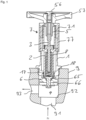
- the non-return valve selected as an exemplary embodiment consists essentially of a head piece 1, which is penetrated by a pressure cylinder 2, which accommodates a pump piston 3 and in which a non-return piston 4 is arranged, to which a conical disk 6 is attached, the pressure cylinder 2 and the pump piston 3 are connected via a spindle 5 to a hand wheel 57, via which they can be displaced axially in the head piece 1 in mutually opposite directions.
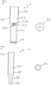
- the head piece 1 is a largely hollow-cylindrical turned brass part. At its lower, fitting-side end, a first external thread 11 is attached to the head piece 1, which is delimited by a circumferential collar 12. An external hexagon 13 connects to the collar 12, which merges into an outer diameter tapered section, at the end of a second External thread 14 for receiving the threaded sleeve 77 of the threaded bell 7 is introduced.
- the external thread 14 is designed as a right-hand trapezoidal thread.
- Inside the head piece 1 at the level of the second external thread 14 is a hexagon socket collar 15 for guiding and preventing the printing cylinder 2 from rotating.
- Two parallel grooves 16 for accommodating O-rings 17 are made in the head piece 1 on its inner side opposite the first external thread 11 .
- An O-ring 18 for sealing against a fitting 9 is arranged on the outside of the head piece 1 below the collar 12 .
- the pressure cylinder 2 is designed as an essentially hollow-cylindrical turned brass part and has a cylindrical first piston chamber 21 and a cylindrical second piston chamber 22 with a larger diameter than this, which are connected to one another via a through-channel 23 .
- the through-channel 23 is provided with a diameter enlargement 231, into which axial notches 232 running over the entire length open circumferentially over its inner lateral surface, whereby a torsion-proof guidance in the manner of a hexagon socket is achieved.
- the first piston chamber 21 of the pressure cylinder 2 has, at its end opposite the through-channel 23 , a shoulder 24 with an enlarged diameter for receiving a slide ring 25 , via which the non-return piston 4 is displaceably guided in the first piston chamber 21 .
- the outer contour of the hexagonal section 26 essentially corresponds to the inner contour of the hexagon socket collar 15 of the head piece 1, through which it is guided.
- the pump piston 3 has a cylindrical piston section 31 which is provided circumferentially on the outside with two spaced-apart grooves 32 in each of which an O-ring 33 is inserted for sealing against the second piston chamber 22 of the pressure cylinder 2 .
- the piston section 31 On its side facing the spindle 5, the piston section 31 extends centrally into a drive rod 34 above, which has a diameter-enlarged section 35 at the end, which is provided with an external thread 36, which is designed as a right-hand trapezoidal thread and via which the drive rod 34 is connected to the spindle 5.
- An annular groove 37 is introduced into the piston section 31 so as to surround the drive rod 34 .
- the piston section 31 transitions into a central guide rod 38 with a hexagonal cross-section, with which it is guided in a torsion-proof manner in the through-channel 23 of the pressure cylinder 2, which it penetrates.
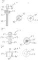
- the spindle 5 is designed as an essentially cylindrical turned brass part.
- the spindle 5 is divided into a cylindrical section 51 and a square-shaped section 52, between which a peripheral collar 53 is arranged, on which a hexagonal shoulder 531 is arranged.
- a first axial threaded bore 54 is introduced centrally into the spindle 5 in the cylindrical section 51 and has a right-hand trapezoidal thread in the exemplary embodiment, in which the drive rod 34 of the pump piston 3 engages with its external thread 36 .
- a second axial threaded bore 55 is introduced centrally, which has a metric internal thread.
- the threaded hole 55 serves to accommodate a screw 56 for fastening the handwheel 57 that is attached to the square section 52.
- a threaded bell 7 is applied to the spindle 5 between the pressure cylinder 2 and the hand wheel 57 .
- the threaded bell 7 is formed from a carrier piece 71 and a threaded sleeve 77.
- the carrier piece 71 is designed as a substantially pot-shaped turned brass part and has a circular disc 72 on which a hollow-cylindrical extension 74 is arranged, which it protrudes all the way around.
- a hexagonal recess 73 is made in the disc 72 , with which the carrier piece 71 of the threaded bell 7 rests on the hexagonal section 531 of the collar 53 of the spindle 5 .
- the threaded bell 7 is thus connected to the spindle 5 in a form-fitting manner.
- the extension 74 is provided on the inside with a first internal thread 75 which is designed as a trapezoidal left-hand thread for engagement with the external thread 27 of the pressure cylinder 2 .
- the projection 74 has a right-hand trapezoidal thread External thread 76 on.
- the threaded sleeve 77 is designed as a hollow-cylindrical turned brass part and is provided with a second internal thread 78, which is designed as a right-hand trapezoidal thread.
- the threaded sleeve 77 is screwed with its second internal thread 78 onto the external thread 76 of the extension 74 of the support piece 71 and glued to it, with it protruding axially beyond the extension 74 of the support piece 71 by about half its length.
- a thermal and/or mechanical non-detachable connection of carrier piece 71 and threaded sleeve 72 is also possible.
- the threaded bell 7 formed in this way has, axially and radially offset from one another, a first internal thread 75 designed as a trapezoidal left-hand thread for engaging with the external thread 27 of the pressure cylinder 2 and a second internal thread 78 designed as a trapezoidal right-hand thread for engaging with the second external thread 14 of the head piece 1 .
- the check piston 4 is designed essentially as a cylindrical turned brass part. At its end facing the through-channel 23 of the pressure cylinder 2 , a blind hole 41 for receiving a spring 8 is introduced axially into the check piston 4 . At its end facing the spindle 5 , an external polygon 42 is arranged on the non-return piston 4 . An intermediate space for the passage of water is thus formed between the non-return piston 4 and the cylindrical first piston space 21 . At its end opposite the external polygon 42 , the non-return piston 4 has a pin 43 for accommodating the conical disk 6 , which at the end merges into a threaded head 44 .
- the outer lateral surface of the non-return piston 4 is provided with a Teflon layer in the entire area that can be displaced axially within the first piston chamber 21 of the pressure cylinder 2 , ie from the outer polygon 42 to the pin 43 .
- the check piston 4 can also be made of a non-corrosive material such as stainless steel.
- Around Blind bore 41 are introduced into the non-return piston 4 pressure compensation bores 45, which are used for the entry or exit of water when the non-return piston 4 moves within the first piston chamber 21.
- the pressure compensation bores 45 open into the intermediate space formed between the check piston 4 and the cylindrical first piston space 21 .
- the conical disk 6 is pushed onto the pin 43 of the check piston 4 .
- the conical disk 6 is designed as a turned brass part.
- a conical shoulder 61 is arranged on the conical disk 6 on its side facing away from the head piece 1 .
- the conical disk 6 On its side opposite the conical shoulder 61 , the conical disk 6 has a section 62 with a reduced diameter.
- the conical disk 6 is centrally provided with a stepped bore 63, which is designed with a larger diameter in the area of the transition to the diameter-reduced section 62, as a result of which a shoulder 64 for receiving an O-ring 65 is formed.
- a sealing disk 66 is placed on the conical shoulder 61 of the conical disk 6 and the conical disk 6 and sealing disk 66 are fastened to the non-return piston 4 by means of a collar nut 46 which is screwed onto the threaded head 44 of the pin 43 .
- the conical disk 6 is sealed off from the pin 43 of the check piston 4 by the O-ring 65 .
- the spindle 5 is screwed with its first threaded bore 54 onto the external thread 36 of the drive rod 34 of the pump piston 3, which is inserted into the second piston chamber 22 of the pressure cylinder, with its piston section 31 being opposite the second piston chamber 22 via the O-rings 33 is sealed and its guide rod 38 projects through the passage 23 of the pressure cylinder 2 into the first piston chamber 21 .
- the threaded bell 7 is pushed onto the collar 53 of the spindle 5 and rests on the collar 53, with the hexagonal shoulder 531 of the collar engaging in the hexagonal recess 73 of the disc 72, as a result of which the threaded bell 7 and the spindle 5 are positively connected.
- the hand wheel 57 is attached to the square section 52 of the spindle 5 and connected to it via the screw 56 which is screwed into the second threaded bore 55 of the spindle 5 .
- the threaded bell 7, which is axially fixed on the spindle 5 via the handwheel 57, is with its first internal thread 75 with the external thread 27 of the pressure cylinder 2 and with its second internal thread 78 with the second external thread 14 of the head piece 1 in engagement.
- the non-return piston 4 is pushed with its external polygon 42 into the cylindrical first piston chamber 21 of the pressure cylinder 2, with a spring 8 being introduced into the non-return piston 4, which is designed as a compression coil spring and which with its other end rests on the base of the first piston chamber 21 of the pressure cylinder 2 rests surrounding the diameter enlargement 231 of the through-channel 23 against which it is prestressed.
- the guide rod 38 protrudes into the blind hole 41 of the check piston 4 and the spring 8 arranged in it.
- the non-return piston 4 is guided in the pressure cylinder 2 via the slide ring 25, which has a pressure equalization gap 251 for the passage of water for pressure equalization.
- the pressure cylinder 2 is sealed off by the two O-rings 17 in relation to the head piece 1, which with its first external thread 11 is screwed into a fitting 9--shown only schematically in the figures.
- the head piece 1 is sealed off from the fitting 9 by the O-ring 18 .
- the fitting 9 includes a water inlet 91 and a water outlet 93.
- the water inlet 91 has a stop 92 against which the sealing disk 66 attached to the check piston 4 rests.
- the check piston 4 is prestressed against the stop 92 by the spring 8 . In this case, no water flows from the water inlet 91 to the water outlet 93.
- the pressure p in the water outlet 93 increases.
- the pressure cylinder 2 is moved by rotating the spindle 5 via the hand wheel 57 in the direction of the conical disk 6 to block the water inlet 91, the threaded engagement between the spindle 5 and the drive rod 34, which runs in the opposite direction to the threaded engagement between the threaded bell 7 and the pressure cylinder 2, also causes the piston section 31 of the pump piston 3 is moved upwards in the direction of spindle 5, as a result of which the water displaced by the pressure cylinder 2 is sucked through the pressure compensation gap 251 of the slide ring 25 via the intermediate space formed between the check piston 4 and the first piston chamber 21, through the through-channel 23 and into the second piston chamber 22.
- the volume available for this purpose in the second piston chamber 22 is maximized by the annular groove 37 arranged in the piston section 31 .
- the increase in diameter 231 of the through-channel 23 ensures that water can flow around the guide rod 38 guided through the through-channel 23 at all times.
- the pressure p present in the water outlet 93 thus remains approximately constant.
- the negative pressure in the blind bore 41 caused by the movement of the non-return piston 4 out of the first piston chamber 21 is compensated for by the pressure compensation bore 45 arranged in this bore.
Landscapes
- Engineering & Computer Science (AREA)
- General Engineering & Computer Science (AREA)
- Mechanical Engineering (AREA)
- Reciprocating Pumps (AREA)
Priority Applications (1)
| Application Number | Priority Date | Filing Date | Title |
|---|---|---|---|
| EP22155598.0A EP4224042B1 (fr) | 2022-02-08 | 2022-02-08 | Clapet anti-retour |
Applications Claiming Priority (1)
| Application Number | Priority Date | Filing Date | Title |
|---|---|---|---|
| EP22155598.0A EP4224042B1 (fr) | 2022-02-08 | 2022-02-08 | Clapet anti-retour |
Publications (3)
| Publication Number | Publication Date |
|---|---|
| EP4224042A1 true EP4224042A1 (fr) | 2023-08-09 |
| EP4224042C0 EP4224042C0 (fr) | 2024-03-13 |
| EP4224042B1 EP4224042B1 (fr) | 2024-03-13 |
Family
ID=80448576
Family Applications (1)
| Application Number | Title | Priority Date | Filing Date |
|---|---|---|---|
| EP22155598.0A Active EP4224042B1 (fr) | 2022-02-08 | 2022-02-08 | Clapet anti-retour |
Country Status (1)
| Country | Link |
|---|---|
| EP (1) | EP4224042B1 (fr) |
Citations (3)
| Publication number | Priority date | Publication date | Assignee | Title |
|---|---|---|---|---|
| JPS5448330A (en) * | 1977-04-15 | 1979-04-16 | Reed Peter | Axial flow regulating valve |
| EP2325533B1 (fr) | 2009-11-19 | 2017-09-13 | Flühs Drehtechnik GmbH | Partie supérieure de soupape |
| DE202021101378U1 (de) | 2021-03-18 | 2021-04-07 | Flühs Drehtechnik GmbH | Rückflussverhindererventil |
-
2022
- 2022-02-08 EP EP22155598.0A patent/EP4224042B1/fr active Active
Patent Citations (3)
| Publication number | Priority date | Publication date | Assignee | Title |
|---|---|---|---|---|
| JPS5448330A (en) * | 1977-04-15 | 1979-04-16 | Reed Peter | Axial flow regulating valve |
| EP2325533B1 (fr) | 2009-11-19 | 2017-09-13 | Flühs Drehtechnik GmbH | Partie supérieure de soupape |
| DE202021101378U1 (de) | 2021-03-18 | 2021-04-07 | Flühs Drehtechnik GmbH | Rückflussverhindererventil |
Also Published As
| Publication number | Publication date |
|---|---|
| EP4224042C0 (fr) | 2024-03-13 |
| EP4224042B1 (fr) | 2024-03-13 |
Similar Documents
| Publication | Publication Date | Title |
|---|---|---|
| DE1182493B (de) | Federbelastetes UEberdruckventil mit Schnappwirkung | |
| DE2435911A1 (de) | Druckabhaengiges ventil | |
| DE112016002550T5 (de) | Integriertes rückschlag-entlastungsventil | |
| WO2018153824A1 (fr) | Partie supérieure de soupape | |
| EP1725796B1 (fr) | Soupape de retenue | |
| EP4060210B1 (fr) | Clapet anti-retour | |
| WO2014131495A2 (fr) | Soupape de trop-plein | |
| DE202022100701U1 (de) | Rückflussverhindererventil | |
| DE2944520A1 (de) | Ventiloberteil | |
| EP4224042B1 (fr) | Clapet anti-retour | |
| EP1001196B1 (fr) | Soupape de limitation de pression, en particulier pour des véhicules | |
| DE202023101160U1 (de) | Ventiloberteil für Sanitärarmaturen | |
| DE202023101163U1 (de) | Ventiloberteil für Sanitärarmaturen | |
| WO2008128839A1 (fr) | Soupape de non-retour | |
| EP0093783B1 (fr) | Soupape à passage directe | |
| EP4286723B1 (fr) | Soupape d'arrêt | |
| DE3840865C2 (fr) | ||
| DE3812233A1 (de) | Wasserventil | |
| DE2213098C3 (de) | Druckbetätigtes Sicherheitsventil für Bohrlochrohrstränge | |
| DE202022103021U1 (de) | Absperrventil | |
| EP4428406B1 (fr) | Partie supérieure de soupape pour robinetteries sanitaires | |
| DE69412427T2 (de) | Kraftstoffeinspritzdüse | |
| EP4428405B1 (fr) | Dispositif de commande pour un élément supérieur de soupape pour robinetteries sanitaires | |
| DE202023101162U1 (de) | Bedieneinrichtung für ein Ventiloberteil für Sanitärarmaturen | |
| DE202023101164U1 (de) | Ventiloberteil für Sanitärarmaturen |
Legal Events
| Date | Code | Title | Description |
|---|---|---|---|
| PUAI | Public reference made under article 153(3) epc to a published international application that has entered the european phase |
Free format text: ORIGINAL CODE: 0009012 |
|
| STAA | Information on the status of an ep patent application or granted ep patent |
Free format text: STATUS: REQUEST FOR EXAMINATION WAS MADE |
|
| 17P | Request for examination filed |
Effective date: 20221024 |
|
| AK | Designated contracting states |
Kind code of ref document: A1 Designated state(s): AL AT BE BG CH CY CZ DE DK EE ES FI FR GB GR HR HU IE IS IT LI LT LU LV MC MK MT NL NO PL PT RO RS SE SI SK SM TR |
|
| GRAP | Despatch of communication of intention to grant a patent |
Free format text: ORIGINAL CODE: EPIDOSNIGR1 |
|
| STAA | Information on the status of an ep patent application or granted ep patent |
Free format text: STATUS: GRANT OF PATENT IS INTENDED |
|
| INTG | Intention to grant announced |
Effective date: 20230925 |
|
| GRAS | Grant fee paid |
Free format text: ORIGINAL CODE: EPIDOSNIGR3 |
|
| GRAA | (expected) grant |
Free format text: ORIGINAL CODE: 0009210 |
|
| STAA | Information on the status of an ep patent application or granted ep patent |
Free format text: STATUS: THE PATENT HAS BEEN GRANTED |
|
| AK | Designated contracting states |
Kind code of ref document: B1 Designated state(s): AL AT BE BG CH CY CZ DE DK EE ES FI FR GB GR HR HU IE IS IT LI LT LU LV MC MK MT NL NO PL PT RO RS SE SI SK SM TR |
|
| REG | Reference to a national code |
Ref country code: GB Ref legal event code: FG4D Free format text: NOT ENGLISH |
|
| REG | Reference to a national code |
Ref country code: CH Ref legal event code: EP |
|
| REG | Reference to a national code |
Ref country code: DE Ref legal event code: R096 Ref document number: 502022000590 Country of ref document: DE |
|
| REG | Reference to a national code |
Ref country code: IE Ref legal event code: FG4D Free format text: LANGUAGE OF EP DOCUMENT: GERMAN |
|
| U01 | Request for unitary effect filed |
Effective date: 20240412 |
|
| U07 | Unitary effect registered |
Designated state(s): AT BE BG DE DK EE FI FR IT LT LU LV MT NL PT SE SI Effective date: 20240418 |
|
| PG25 | Lapsed in a contracting state [announced via postgrant information from national office to epo] |
Ref country code: GR Free format text: LAPSE BECAUSE OF FAILURE TO SUBMIT A TRANSLATION OF THE DESCRIPTION OR TO PAY THE FEE WITHIN THE PRESCRIBED TIME-LIMIT Effective date: 20240614 |
|
| PG25 | Lapsed in a contracting state [announced via postgrant information from national office to epo] |
Ref country code: RS Free format text: LAPSE BECAUSE OF FAILURE TO SUBMIT A TRANSLATION OF THE DESCRIPTION OR TO PAY THE FEE WITHIN THE PRESCRIBED TIME-LIMIT Effective date: 20240613 Ref country code: HR Free format text: LAPSE BECAUSE OF FAILURE TO SUBMIT A TRANSLATION OF THE DESCRIPTION OR TO PAY THE FEE WITHIN THE PRESCRIBED TIME-LIMIT Effective date: 20240313 |
|
| PG25 | Lapsed in a contracting state [announced via postgrant information from national office to epo] |
Ref country code: ES Free format text: LAPSE BECAUSE OF FAILURE TO SUBMIT A TRANSLATION OF THE DESCRIPTION OR TO PAY THE FEE WITHIN THE PRESCRIBED TIME-LIMIT Effective date: 20240313 |
|
| PG25 | Lapsed in a contracting state [announced via postgrant information from national office to epo] |
Ref country code: RS Free format text: LAPSE BECAUSE OF FAILURE TO SUBMIT A TRANSLATION OF THE DESCRIPTION OR TO PAY THE FEE WITHIN THE PRESCRIBED TIME-LIMIT Effective date: 20240613 Ref country code: NO Free format text: LAPSE BECAUSE OF FAILURE TO SUBMIT A TRANSLATION OF THE DESCRIPTION OR TO PAY THE FEE WITHIN THE PRESCRIBED TIME-LIMIT Effective date: 20240613 Ref country code: HR Free format text: LAPSE BECAUSE OF FAILURE TO SUBMIT A TRANSLATION OF THE DESCRIPTION OR TO PAY THE FEE WITHIN THE PRESCRIBED TIME-LIMIT Effective date: 20240313 Ref country code: GR Free format text: LAPSE BECAUSE OF FAILURE TO SUBMIT A TRANSLATION OF THE DESCRIPTION OR TO PAY THE FEE WITHIN THE PRESCRIBED TIME-LIMIT Effective date: 20240614 Ref country code: ES Free format text: LAPSE BECAUSE OF FAILURE TO SUBMIT A TRANSLATION OF THE DESCRIPTION OR TO PAY THE FEE WITHIN THE PRESCRIBED TIME-LIMIT Effective date: 20240313 |
|
| PG25 | Lapsed in a contracting state [announced via postgrant information from national office to epo] |
Ref country code: IS Free format text: LAPSE BECAUSE OF FAILURE TO SUBMIT A TRANSLATION OF THE DESCRIPTION OR TO PAY THE FEE WITHIN THE PRESCRIBED TIME-LIMIT Effective date: 20240713 |
|
| PG25 | Lapsed in a contracting state [announced via postgrant information from national office to epo] |
Ref country code: SM Free format text: LAPSE BECAUSE OF FAILURE TO SUBMIT A TRANSLATION OF THE DESCRIPTION OR TO PAY THE FEE WITHIN THE PRESCRIBED TIME-LIMIT Effective date: 20240313 |
|
| PG25 | Lapsed in a contracting state [announced via postgrant information from national office to epo] |
Ref country code: CZ Free format text: LAPSE BECAUSE OF FAILURE TO SUBMIT A TRANSLATION OF THE DESCRIPTION OR TO PAY THE FEE WITHIN THE PRESCRIBED TIME-LIMIT Effective date: 20240313 |
|
| PG25 | Lapsed in a contracting state [announced via postgrant information from national office to epo] |
Ref country code: PL Free format text: LAPSE BECAUSE OF FAILURE TO SUBMIT A TRANSLATION OF THE DESCRIPTION OR TO PAY THE FEE WITHIN THE PRESCRIBED TIME-LIMIT Effective date: 20240313 |
|
| PG25 | Lapsed in a contracting state [announced via postgrant information from national office to epo] |
Ref country code: SK Free format text: LAPSE BECAUSE OF FAILURE TO SUBMIT A TRANSLATION OF THE DESCRIPTION OR TO PAY THE FEE WITHIN THE PRESCRIBED TIME-LIMIT Effective date: 20240313 |
|
| PG25 | Lapsed in a contracting state [announced via postgrant information from national office to epo] |
Ref country code: SM Free format text: LAPSE BECAUSE OF FAILURE TO SUBMIT A TRANSLATION OF THE DESCRIPTION OR TO PAY THE FEE WITHIN THE PRESCRIBED TIME-LIMIT Effective date: 20240313 Ref country code: SK Free format text: LAPSE BECAUSE OF FAILURE TO SUBMIT A TRANSLATION OF THE DESCRIPTION OR TO PAY THE FEE WITHIN THE PRESCRIBED TIME-LIMIT Effective date: 20240313 Ref country code: RO Free format text: LAPSE BECAUSE OF FAILURE TO SUBMIT A TRANSLATION OF THE DESCRIPTION OR TO PAY THE FEE WITHIN THE PRESCRIBED TIME-LIMIT Effective date: 20240313 Ref country code: PL Free format text: LAPSE BECAUSE OF FAILURE TO SUBMIT A TRANSLATION OF THE DESCRIPTION OR TO PAY THE FEE WITHIN THE PRESCRIBED TIME-LIMIT Effective date: 20240313 Ref country code: IS Free format text: LAPSE BECAUSE OF FAILURE TO SUBMIT A TRANSLATION OF THE DESCRIPTION OR TO PAY THE FEE WITHIN THE PRESCRIBED TIME-LIMIT Effective date: 20240713 Ref country code: CZ Free format text: LAPSE BECAUSE OF FAILURE TO SUBMIT A TRANSLATION OF THE DESCRIPTION OR TO PAY THE FEE WITHIN THE PRESCRIBED TIME-LIMIT Effective date: 20240313 |
|
| REG | Reference to a national code |
Ref country code: DE Ref legal event code: R097 Ref document number: 502022000590 Country of ref document: DE |
|
| PLBE | No opposition filed within time limit |
Free format text: ORIGINAL CODE: 0009261 |
|
| STAA | Information on the status of an ep patent application or granted ep patent |
Free format text: STATUS: NO OPPOSITION FILED WITHIN TIME LIMIT |
|
| 26N | No opposition filed |
Effective date: 20241216 |
|
| U20 | Renewal fee for the european patent with unitary effect paid |
Year of fee payment: 4 Effective date: 20250204 |
|
| PG25 | Lapsed in a contracting state [announced via postgrant information from national office to epo] |
Ref country code: MC Free format text: LAPSE BECAUSE OF FAILURE TO SUBMIT A TRANSLATION OF THE DESCRIPTION OR TO PAY THE FEE WITHIN THE PRESCRIBED TIME-LIMIT Effective date: 20240313 |
|
| PG25 | Lapsed in a contracting state [announced via postgrant information from national office to epo] |
Ref country code: IE Free format text: LAPSE BECAUSE OF NON-PAYMENT OF DUE FEES Effective date: 20250208 |
|
| REG | Reference to a national code |
Ref country code: CH Ref legal event code: U11 Free format text: ST27 STATUS EVENT CODE: U-0-0-U10-U11 (AS PROVIDED BY THE NATIONAL OFFICE) Effective date: 20260301 |
|
| U20 | Renewal fee for the european patent with unitary effect paid |
Year of fee payment: 5 Effective date: 20260203 |
|
| PGFP | Annual fee paid to national office [announced via postgrant information from national office to epo] |
Ref country code: CH Payment date: 20260301 Year of fee payment: 5 |