EP4224199A2 - Verfahren zur kalibrierung eines rasenmähers, elektronische vorrichtung, speichermedium und rasenmäher - Google Patents
Verfahren zur kalibrierung eines rasenmähers, elektronische vorrichtung, speichermedium und rasenmäher Download PDFInfo
- Publication number
- EP4224199A2 EP4224199A2 EP23151367.2A EP23151367A EP4224199A2 EP 4224199 A2 EP4224199 A2 EP 4224199A2 EP 23151367 A EP23151367 A EP 23151367A EP 4224199 A2 EP4224199 A2 EP 4224199A2
- Authority
- EP
- European Patent Office
- Prior art keywords
- lawnmower
- charging station
- position data
- calibration
- orientation
- Prior art date
- Legal status (The legal status is an assumption and is not a legal conclusion. Google has not performed a legal analysis and makes no representation as to the accuracy of the status listed.)
- Pending
Links
Images




Classifications
-
- A—HUMAN NECESSITIES
- A01—AGRICULTURE; FORESTRY; ANIMAL HUSBANDRY; HUNTING; TRAPPING; FISHING
- A01D—HARVESTING; MOWING
- A01D34/00—Mowers; Mowing apparatus of harvesters
- A01D34/006—Control or measuring arrangements
- A01D34/008—Control or measuring arrangements for automated or remotely controlled operation
-
- G—PHYSICS
- G05—CONTROLLING; REGULATING
- G05D—SYSTEMS FOR CONTROLLING OR REGULATING NON-ELECTRIC VARIABLES
- G05D1/00—Control of position, course, altitude or attitude of land, water, air or space vehicles, e.g. using automatic pilots
- G05D1/02—Control of position or course in two dimensions
- G05D1/021—Control of position or course in two dimensions specially adapted to land vehicles
- G05D1/0276—Control of position or course in two dimensions specially adapted to land vehicles using signals provided by a source external to the vehicle
- G05D1/0278—Control of position or course in two dimensions specially adapted to land vehicles using signals provided by a source external to the vehicle using satellite positioning signals, e.g. GPS
-
- G—PHYSICS
- G01—MEASURING; TESTING
- G01C—MEASURING DISTANCES, LEVELS OR BEARINGS; SURVEYING; NAVIGATION; GYROSCOPIC INSTRUMENTS; PHOTOGRAMMETRY OR VIDEOGRAMMETRY
- G01C21/00—Navigation; Navigational instruments not provided for in groups G01C1/00 - G01C19/00
- G01C21/005—Navigation; Navigational instruments not provided for in groups G01C1/00 - G01C19/00 with correlation of navigation data from several sources, e.g. map or contour matching
-
- G—PHYSICS
- G01—MEASURING; TESTING
- G01S—RADIO DIRECTION-FINDING; RADIO NAVIGATION; DETERMINING DISTANCE OR VELOCITY BY USE OF RADIO WAVES; LOCATING OR PRESENCE-DETECTING BY USE OF THE REFLECTION OR RERADIATION OF RADIO WAVES; ANALOGOUS ARRANGEMENTS USING OTHER WAVES
- G01S19/00—Satellite radio beacon positioning systems; Determining position, velocity or attitude using signals transmitted by such systems
- G01S19/38—Determining a navigation solution using signals transmitted by a satellite radio beacon positioning system
- G01S19/39—Determining a navigation solution using signals transmitted by a satellite radio beacon positioning system the satellite radio beacon positioning system transmitting time-stamped messages, e.g. GPS [Global Positioning System], GLONASS [Global Orbiting Navigation Satellite System] or GALILEO
- G01S19/53—Determining attitude
-
- G—PHYSICS
- G01—MEASURING; TESTING
- G01S—RADIO DIRECTION-FINDING; RADIO NAVIGATION; DETERMINING DISTANCE OR VELOCITY BY USE OF RADIO WAVES; LOCATING OR PRESENCE-DETECTING BY USE OF THE REFLECTION OR RERADIATION OF RADIO WAVES; ANALOGOUS ARRANGEMENTS USING OTHER WAVES
- G01S5/00—Position-fixing by co-ordinating two or more direction or position line determinations; Position-fixing by co-ordinating two or more distance determinations
- G01S5/02—Position-fixing by co-ordinating two or more direction or position line determinations; Position-fixing by co-ordinating two or more distance determinations using radio waves
- G01S5/0284—Relative positioning
-
- G—PHYSICS
- G05—CONTROLLING; REGULATING
- G05D—SYSTEMS FOR CONTROLLING OR REGULATING NON-ELECTRIC VARIABLES
- G05D1/00—Control of position, course, altitude or attitude of land, water, air or space vehicles, e.g. using automatic pilots
- G05D1/02—Control of position or course in two dimensions
- G05D1/021—Control of position or course in two dimensions specially adapted to land vehicles
- G05D1/0276—Control of position or course in two dimensions specially adapted to land vehicles using signals provided by a source external to the vehicle
- G05D1/028—Control of position or course in two dimensions specially adapted to land vehicles using signals provided by a source external to the vehicle using a RF signal
-
- G—PHYSICS
- G01—MEASURING; TESTING
- G01S—RADIO DIRECTION-FINDING; RADIO NAVIGATION; DETERMINING DISTANCE OR VELOCITY BY USE OF RADIO WAVES; LOCATING OR PRESENCE-DETECTING BY USE OF THE REFLECTION OR RERADIATION OF RADIO WAVES; ANALOGOUS ARRANGEMENTS USING OTHER WAVES
- G01S19/00—Satellite radio beacon positioning systems; Determining position, velocity or attitude using signals transmitted by such systems
- G01S19/38—Determining a navigation solution using signals transmitted by a satellite radio beacon positioning system
- G01S19/39—Determining a navigation solution using signals transmitted by a satellite radio beacon positioning system the satellite radio beacon positioning system transmitting time-stamped messages, e.g. GPS [Global Positioning System], GLONASS [Global Orbiting Navigation Satellite System] or GALILEO
- G01S19/42—Determining position
- G01S19/43—Determining position using carrier phase measurements, e.g. kinematic positioning; using long or short baseline interferometry
Definitions
- the existing method for determining an orientation of a charging station of a lawnmower in the local Cartesian coordinate system usually includes two methods.
- the first method is to use a geomagnetic sensor to measure a direction of the magnetic field, and calculate a magnetic declination by obtaining the latitude and longitude to obtain orientation information of the charging station of the lawnmower in the ENU coordinate system; and the second method is to obtain orientation information of the charging station of the lawnmower by installing dual RTK antennas.
- the geomagnetic sensor may be easily disturbed by a surrounding magnetic field, resulting in inaccurate measurement results and large errors in travel direction, and the method relies on GPS to obtain the latitude, longitude and altitude of the lawnmower to calculate the magnetic declination, which is very complicated and costly; in the second method, costs of the dual RTK antennas are relatively high, and there are also high requirements for antenna installation accuracy, which leads to the problem of difficult antenna installation.
- an embodiment of the present disclosure provides a lawnmower calibration scheme having higher accuracy and lower cost, so as to at least partly solve the above problems.
- a method for calibrating a lawnmower including: collecting a preset number of position data during moving of the lawnmower relative to a charging station; performing straight line fitting using the preset number of the position data; and determining, if the preset number of the position data fits a straight line, an orientation of the charging station based on a slope of the fitted straight line.
- another method for calibrating a lawnmower including: determining, during moving of a lawnmower relative to a charging station, an orientation of the charging station, based on a plurality of position data and pose data of the lawnmower; and sending first indication information for indicating successful determination, if the orientation of the charging station is determined.
- another method for calibrating a lawnmower including: displaying a calibration option in a display interface, and sending a calibration trigger instruction to the lawnmower when the calibration option is triggered; and displaying, if first indication information is received from the lawnmower in response to the calibration trigger instruction, calibration success prompt information in the display interface, wherein the first indication information is determined based on a successfully determined orientation of a charging station, and the orientation of the charging station is determined based on a plurality of position data and pose data during moving of the lawnmower relative to the charging station.
- an apparatus for calibrating a lawnmower including: a collection module, configured to collect a preset number of position data during moving of the lawnmower relative to a charging station; a fitting module, configured to perform straight line fitting using the preset number of the position data; and a determination module, configured to determine, if the preset number of the position data fits a straight line, an orientation of the charging station based on a slope of the fitted straight line.
- an electronic device including: a processor; and a memory, for storing a program; wherein, the program includes instructions, the instructions, when executed by the processor, cause the processor to perform the method for calibrating a lawnmower described in the above aspect.
- the scheme for calibrating a lawnmower determines the orientation of the charging station by collecting measurement data during the movement of the lawnmower relative to the charging station and performing straight line fitting based on the measurement data. Accordingly, embodiments of the present disclosure may accurately determine the orientation of the charging station and has the advantages of high calibration accuracy and low calibration cost.
- the current method for determining an orientation of a charging station of a lawnmower in the local Cartesian coordinate system has problems of inaccurate measurement accuracy and high cost of measurement configuration (RTK antenna cost), in view of this, embodiments of the present disclosure provides a scheme for calibrating a lawnmower that can accurately determine an orientation of a charging station of a lawnmower, to improve the various problems in the prior art.
- the method may be applied when a lawnmower is first started, such as when a user purchases a lawnmower and activates it for the first time.
- an orientation of a charging station of the lawnmower may be calibrated (it should be noted that the orientation calibration described in embodiments of the present disclosure may be understood as detecting or determining the orientation), after the calibration, the lawnmower may be controlled to start mapping, then, based on a map built, the lawnmower mows grass automatically.
- the method may be applied to other scenarios where the orientation of the charging station needs to be determined or calibrated, and is not limited to the scenarios exemplified in this embodiment.
- the lawnmower may be driven to move in a direction along a straight line away from the charging station in a pose corresponding to an initialized position, and the preset number of position data of the lawnmower during the movement may be collected.
- a rotation angle of a pose of the lawnmower at each position where the position data is collected relative to a pose of the lawnmower corresponding to the initialized position is less than an angle threshold.
- a pair of RTK antennas respectively set at a preset position and on the lawnmower may be used to acquire the preset number of position data (also known as RTK measurement points) of the lawnmower in the local Cartesian coordinate system (or ENU coordinate system).
- a pair of RTK antennas respectively set on the charging station and the lawnmower may be used to acquire each position data of the lawnmower.
- Step S 104 performing straight line fitting using the preset number of position data.
- the preset number may be set to 26, i.e., when the collected position data of the lawnmower reaches 26, straight line fitting is performed.
- Step S106 determining, if the preset number of position data fits a straight line, an orientation of the charging station based on a slope of the fitted straight line.
- the orientation of the charging station (also known as pose of the charging station) may be determined based on the slope of the fitted straight line.
- the orientation of the charging station is an outlet orientation of the charging station, that is, orientation of a charging tongue on the charging station.
- the lawnmower may return to the charging station and establish an electrical connection with it to perform a charging operation of the lawnmower based on the determined orientation of the charging station.
- the method for calibrating a lawnmower in this embodiment by collecting the preset number of measurement data during the movement of the lawnmower relative to the charging station, to perform straight line fitting, determines the orientation of the charging station based on the fitted straight line. Therefore, this embodiment may accurately determine the orientation of the charging station and has the advantages of simple calibration operation and low calibration cost.
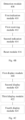
- Fig. 2 illustrates a processing flow of the method for calibrating a lawnmower according to another exemplary embodiment of the present disclosure. As shown in the figure, this embodiment mainly includes the following steps: Step S202, determining whether the lawnmower is in a docking state with the charging station, if yes, proceeding to step S204, otherwise repeat performing this step.
- Step S204 using a position where the lawnmower is in the docking state as an initialized position, and acquiring initial position data corresponding to the initialized position.
- the preset number of position data includes the initial position data.
- Step S206 driving the lawnmower to move in a direction along a straight line away from the charging station in a pose corresponding to the initialized position.
- the lawnmower may be driven to move backward in a straight line relative to the charging station in the pose corresponding to the initialized position.
- Step S208 acquiring the position data and angle data of the lawnmower during the movement of the lawnmower.
- a pair of RTK antennas respectively set on the charging station and the lawnmower may be used to acquire each position data of the lawnmower.
- a sampling frequency of 10Hz may be used to collect each moving position of the lawnmower.
- the angle data of the lawnmower may be acquired using an inertial measurement unit provided on the lawnmower.
- Step S210 determining a rotation angle of a pose of the lawnmower at a current moment relative to the pose corresponding to the initialized position based on the angle data.
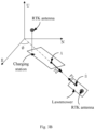
- the rotation angle (e.g., rotation angle a shown in Fig. 3C ) of the pose of the lawnmower at the current moment relative to the pose corresponding to the initialized position may be determined based on the angle data.
- Step S212 determining whether the rotation angle is greater than a set angle threshold, if yes, proceeding to step S214, otherwise continue performing step S216.
- the set angle threshold may be set to 20°, but is not limited thereto, and may be adjusted arbitrarily according to actual calibration needs, which is not limited in the embodiment of the present disclosure.
- Step S214 clearing the acquired position data, and re-determining the initialized position with a position at the current moment, acquiring position data of the lawnmower at the current moment, and resetting the inertial measurement unit, and returning to step S206 to continue execution.
- a measurement value of the inertial measurement unit is reset to 0, and return to step S206 to continue execution.
- Step S216 determining whether a distance of the position of the lawnmower at the current moment relative to the initialized position exceeds a set distance threshold, if not exceeded, performing step S218, if exceeded, returning to step S202 to continue execution.
- the distance of the position of the lawnmower at the current moment relative to the initialized position may be determined using an encoder provided on the lawnmower.
- the encoder may include a magnetic encoder.
- the set distance threshold may be set to 2m, but is not limited thereto, and may be adjusted arbitrarily according to actual calibration needs.
- Step S218, determining whether the number of the acquired position data satisfies the preset number, if yes, proceeding to step S220, if not, returning to step S208 to continue execution.
- step S220 when it is determined that the number of the acquired position data reaches 26, proceeding to step S220.
- Step S220 performing straight line fitting using the preset number of position data.
- performing straight line fitting using at least 26 position data For example, performing straight line fitting using at least 26 position data.
- Step S222 determining whether the straight line fitting is successful, if yes, proceeding to step S224, if not, returning to step S208 to continue execution.
- Step S224 determining an orientation of the charging station based on a slope of the fitted straight line.
- a travel direction of the lawnmower may be determined based on the slope of the fitted straight line
- the rotation angle of the pose of the lawnmower at the current moment relative to the pose corresponding to the initialized position may be determined based on the angle data of the inertial measurement unit
- the orientation of the charging station may be determined based on the rotation angle and the travel direction of the lawnmower.
- the outlet orientation of the charging station (as shown in Fig. 3B in a direction of F2 arrow) may be determined based on the travel direction of the lawnmower (as shown in Fig. 3B in a direction of F 1 arrow) and the rotation angle of the lawnmower.
- the method for calibrating a lawnmower in this embodiment of the present disclosure determines the initialized position of the lawnmower by determining the state of the lawnmower docking with the charging station, and performs calibration operation of the lawnmower by collecting the preset number of position data during the movement of the lawnmower along a straight line in a direction away from the charging station in the pose corresponding to the initialized position and performing straight line fitting, which has the advantages of simple calibration operation and no human intervention, and may reduce the problem that the accuracy of calibration results is affected by operational errors during human intervention.
- the distance threshold by setting the distance threshold, and during calibration, when it is judged that the distance of the position of the lawnmower at the current moment relative to the initialized position exceeds the distance threshold, it may be determined that the calibration fails and the lawnmower is driven back to the position of the charging station to wait for a next round of calibration.
- this embodiment only needs to configure a single RTK antenna, the inertial measurement unit and the encoder to accurately determine the orientation of the charging station, and requires fewer types of sensors, which may effectively reduce a calculation cost of the orientation of the charging station.
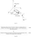
- Step S302 determining, during moving of a lawnmower relative to a charging station, an orientation of the charging station, based on a plurality of position data and pose data of the lawnmower.
- one of a pair of RTK antennas is mounted on the lawnmower, the other of the pair of RTK antennas is mounted on the charging station, in addition, the lawnmower is also equipped with an inertial measurement unit and an encoder.
- the lawnmower In an initial state, the lawnmower is docked with the charging station, and the lawnmower may withdraw from the charging station in its current pose. During the withdrawal, the position data of the lawnmower may be detected through a pair of RTK antennas, and the pose data of the lawnmower may be detected through the inertial measurement unit. Based on the collected position data and pose data, the orientation of the charging station may be determined.
- step S302 may be implemented through the following sub-steps: Sub-step S3021: collecting, during withdrawal of the lawnmower from the charging station, a withdrawal distance of the lawnmower, the position data and the pose data of the lawnmower, respectively.
- the position data of the lawnmower is collected through the RTK antennas, and the pose data of the lawnmower is detected through the inertial measurement unit.
- the pose data may indicate an angle by which the lawnmower is deflected from an initial pose.
- the withdrawal distance of the lawnmower relative to the charging station (that is, an initial position) may be collected through the encoder on the lawnmower.
- Safety of the lawnmower may be ensured by detecting the withdrawal distance, avoiding danger caused by short safety distance near the charging station and long moving distance of the lawnmower during the calibration.
- the withdrawal distance of the lawnmower is detected to avoid excessive withdrawal distance of the lawnmower. If the currently detected withdrawal distance of the lawnmower exceeds the set distance threshold, it indicates that there is danger, and sub-step S3023 may be performed.
- a rotation angle of a pose of the lawnmower relative to the initial position may be determined based on the pose data of the lawnmower. If the rotation angle is greater than an angle threshold, it indicates that a backward trajectory of the lawnmower relative to the charging station is no longer a straight line, but may form a broken-line trajectory similar to that shown in Fig. 3C , which makes it difficult to ensure that the determined orientation of the charging station is accurate, therefore, in this case, sub-step S3024 may be performed.
- sub-step S3022 may be performed.
- Sub-step S3022 if the number of the collected position data reaches a preset number and the withdrawal distance does not exceed a set distance threshold, and a rotation angle indicated by the pose data of the lawnmower does not exceed an angle threshold, determining the orientation of the charging station based on the preset number of collected position data.
- the orientation of the charging station may be determined by performing straight line fitting using the preset number of position data. If a straight line is fitted, the orientation of the charging station may be determined based on the fitted straight line. Since the rotation angle indicated by the pose data exceeds the angle threshold, a direction of the fitted straight line may be used as the orientation of the charging station.
- Sub-step S3023 if the withdrawal distance exceeds the distance threshold, sending second indication information for indicating calibration failure.
- this step is optional.
- the second indication information indicating the calibration failure is sent to facilitate a user to learn the calibration failure information.
- the second indication information may be sent to a display device (such as the user's mobile phone) communicatively connected with the lawnmower, but is not limited thereto.
- Sub-step S3024 if the rotation angle indicated by the pose data exceeds the angle threshold and the withdrawal distance does not exceed the distance threshold, clearing the collected position data and using a current position and a current pose as an initial position and an initial pose, returning to sub-step S3021 to continue execution.
- the collected position data may be cleared, calibration may be re-started from the current position as the initial position, and the current pose as the initial pose, so that the orientation of the charging station can be determined.
- the angle threshold such as 20°
- Step S304 sending first indication information for indicating successful determination, if the orientation of the charging station is determined.
- the first indication information may be sent to a device connected to the lawnmower to indicate that the determination of the orientation of the charging station is successful.
- the device may be a mobile phone, etc. that communicates with the lawnmower, but is not limited thereto.
- the first indication information may be actively sent to facilitate the user to learn that the determination of the orientation of the charging station is completed, which improves user perception, so that the user can learn actions of the lawnmower more intuitively and quickly.
- a method for calibrating a lawnmower includes the following steps: Step S306: displaying a calibration option in a display interface, and sending a calibration trigger instruction to the lawnmower when the calibration option is triggered.
- the display interface may be displayed by a device such as a mobile phone, and the calibration option on the display interface may be a button or other options that can interact with the user.
- the calibration trigger instruction is sent to the lawnmower, so that the lawnmower automatically starts to calibrate an orientation of a charging station.
- the calibration process may be implemented by using the aforementioned method. If the lawnmower successfully calibrates the orientation of the charging station, it sends first indication information to the mobile phone, and the first indication information indicates that the orientation of the charging station is successfully calibrated. In this embodiment, the first indication information is determined based on the successfully determined orientation of the charging station, and the orientation of the charging station is determined based on a plurality of position data and pose data during moving of the lawnmower relative to the charging station.
- Step S308 displaying, if the first indication information is received from the lawnmower in response to the calibration trigger instruction, calibration success prompt information in the display interface.
- the method further includes: Step S310: displaying, when a display duration of the calibration success prompt information satisfies a set duration or when a trigger operation is received on a start mapping option in the display interface of the calibration success prompt information, a remote control interface for remote control of the lawnmower for mapping in the display interface.
- the lawnmower may automatically build a map after the orientation calibration of the charging station is completed. Therefore, after the calibration success prompt information is displayed for a period of time (such as 2 seconds or 3 seconds), the remote control interface for remote control of the lawnmower for mapping may be automatically displayed in the display interface, allowing the user to control the lawnmower for mapping through the mobile phone.
- the set duration such as 2 seconds or 3 seconds
- the remote control interface for remote control of the lawnmower for mapping may be automatically displayed in the display interface, allowing the user to control the lawnmower for mapping through the mobile phone.
- the remote control interface for remote control of the lawnmower for mapping may be displayed in the display interface.
- Step S306a displaying calibration progress information in the display interface during the movement of the lawnmower relative to the charging station.
- the calibration progress information is acquired by communicating with the lawnmower, where the calibration progress information is determined based on the number of collected position data of the lawnmower. If a total of 26 position data needs to be collected, and 10 are currently collected, then the calibration progress is 38%. After collecting 26 position data and fitting a straight line, it may be determined that the calibration progress is 100%.
- the method may display some information during the calibration of the lawnmower to the user, thereby facilitating the user to understand the calibration process and calibration results, and making it more convenient for the user to operate and use the lawnmower.
- Fig. 4A shows a schematic diagram of an architecture of an apparatus for calibrating a lawnmower according to an exemplary embodiment of the present disclosure.
- the apparatus 400 for calibrating a lawnmower in this embodiment mainly includes: A collection module 402, is configured to collect a preset number of position data during moving of the lawnmower relative to a charging station.
- a fitting module 404 is configured to perform straight line fitting using the preset number of position data.
- a determination module 406 is configured to determine, if the preset number of position data fits a straight line, an orientation of the charging station based on a slope of the fitted straight line.
- the collection module 402 is further configured to: use a position where the lawnmower is in the docking state as an initialized position, and acquire initial position data corresponding to the initialized position, if it is determined that the lawnmower is in a docking state with the charging station, wherein the preset number of position data includes the initial position data.
- the collection module 402 is further configured to: drive the lawnmower to move in a direction along a straight line away from the charging station in a pose corresponding to the initialized position, and collect the preset number of position data of the lawnmower during the movement.
- the lawnmower is provided with an inertial measurement unit
- the collection module 402 is further configured to: drive the lawnmower to move in the direction along the straight line away from the charging station in the pose corresponding to the initialized position; acquire the position data during the movement of the lawnmower, and acquire angle data of the inertial measurement unit; determine a rotation angle of a pose of the lawnmower at a current moment relative to the pose corresponding to the initialized position based on the angle data; if the rotation angle is greater than a set angle threshold, clear the acquired position data, and redetermine the initialized position with a position at the current moment, acquire position data of the lawnmower at the current moment, and reset the inertial measurement unit; and return to the step of driving the lawnmower to move in a direction along a straight line away from the charging station in a pose corresponding to the initialized position to continue execution.
- the collection module 402 is further configured to: if the number of the acquired position data does not satisfy the preset number, return to the step of acquiring the position data during the movement of the lawnmower, and acquiring angle data of the inertial measurement unit to continue execution.
- the fitting module 404 is further configured to: determine a travel direction of the lawnmower based on the slope of the fitted straight line; determine the rotation angle of the pose of the lawnmower at the current moment relative to the pose corresponding to the initialized position based on the angle data of the inertial measurement unit; and determine the orientation of the charging station based on the rotation angle and the travel direction of the lawnmower.
- Embodiments of the present disclosure also provides a lawnmower, including a controller, and the controller may be configured to: collect a preset number of position data during moving of the lawnmower relative to a charging station; perform straight line fitting using the preset number of position data; and determine, if the preset number of position data fits a straight line, an orientation of the charging station based on a slope of the fitted straight line.
- Embodiments of the present disclosure also provides a non-transitory computer readable storage medium, storing computer instructions thereon, the computer instructions are used to cause the computer to perform the method according to any one of the above embodiments.
- An exemplary embodiment of the present disclosure also provides an electronic device, including: at least one processor; and a memory communicatively connected to the at least one processor.
- the memory stores a computer program capable of being executed by the at least one processor, the computer program, when executed by the at least one processor, cause the electronic device to perform the method for calibrating a lawnmower according to any one of the above embodiments.
- Fig. 4B shows a structural block diagram of an apparatus for calibrating a lawnmower according to an embodiment of the present disclosure, and the apparatus includes:
- the position data is obtained through detection by a pair of RTK antennas mounted on the lawnmower and the charging station, and the pose data is obtained through detection by an inertial measurement unit mounted on the lawnmower.
- the detection module 408 is configured to: collect, during withdrawal of the lawnmower from the charging station, a withdrawal distance of the lawnmower, the position data and the pose data of the lawnmower, respectively; and if the number of the collected position data reaches a preset number and the withdrawal distance does not exceed a set distance threshold, and a rotation angle indicated by the pose data of the lawnmower does not exceed an angle threshold, determine the orientation of the charging station based on the preset number of collected position data.
- the detection module 408 is configured to: perform straight line fitting using the preset number of the position data, and if a straight line is fitted, determine the orientation of the charging station based on the fitted straight line.
- the apparatus further includes:
- Fig. 4C shows a structural block diagram of an apparatus for calibrating a lawnmower according to an embodiment of the present disclosure, and the apparatus includes:
- the apparatus further includes:
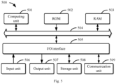
- FIG. 5 a structural block diagram of an electronic device 500 that can serve as a server or a client of an embodiment of the present disclosure will be described, which is an example of a hardware device that can be applied to various aspects of the embodiment of the present disclosure.
- the electronic device is intended to represent various forms of digital computers, such as laptop computers, desktop computers, workbenches, personal digital assistants, servers, blade servers, mainframe computers, and other suitable computers.
- the electronic device may also represent various forms of mobile apparatuses, such as personal digital processors, cellular phones, smart phones, wearable devices, and other similar computing apparatuses.
- the components shown herein, their connections and relationships, and their functions are merely examples, and are not intended to limit the implementation of embodiments of the present disclosure described and/or claimed herein.
- the electronic device 500 includes a computing unit 501, which may perform various appropriate actions and processing, based on a computer program stored in a read-only memory (ROM) 502 or a computer program loaded from a storage unit 508 into a random access memory (RAM) 503.
- ROM read-only memory
- RAM random access memory
- various programs and data required for the operation of the device 500 may also be stored.
- the computing unit 501, the ROM 502, and the RAM 503 are connected to each other through a bus 504.
- An input/output (I/O) interface 505 is also connected to the bus 504.
- the computing unit 501 may be various general-purpose and/or dedicated processing components having processing and computing capabilities. Some examples of the computing unit 501 include, but are not limited to, central processing unit (CPU), graphics processing unit (GPU), various dedicated artificial intelligence (AI) computing chips, various computing units running machine learning model algorithms, digital signal processors (DSP), and any appropriate processors, controllers, microcontrollers, etc.
- the computing unit 501 performs the various methods and processes described above.
- the method for calibrating a lawnmower may be implemented as a computer software program, which is tangibly included in a machine readable medium, such as the storage unit 508.
- part or all of the computer program may be loaded and/or installed on the electronic device 500 via the ROM 502 and/or the communication unit 509.
- the computing unit 501 may be configured to perform the above method for calibrating a lawnmower by any other appropriate means (for example, by means of firmware).
- Program codes used to implement the method of embodiments of embodiments of the present disclosure may be written in any combination of one or more programming languages. These program codes may be provided to a processor or controller of a general-purpose computer, particular-purpose computer or other programmable data processing apparatus, so that the program codes, when executed by the processor or the controller, cause the functions or operations specified in the flowcharts and/or block diagrams to be implemented. These program codes may be executed entirely on a machine, partly on the machine, partly on the machine as a stand-alone software package and partly on a remote machine, or entirely on the remote machine or a server.
- the machine-readable medium may be a tangible medium that may include or store a program for use by or in connection with an instruction execution system, apparatus or device.
- the machine-readable medium may be a machine-readable signal medium or a machine-readable storage medium.
- the machine-readable medium may include, but is not limited to, an electronic, magnetic, optical, electromagnetic, infrared, or semiconductor system, apparatus or device, or any appropriate combination thereof.
- a more particular example of the machine-readable storage medium may include an electronic connection based on one or more lines, a portable computer disk, a hard disk, a random-access memory (RAM), a read-only memory (ROM), an erasable programmable read-only memory (EPROM or flash memory), an optical fiber, a portable compact disk read-only memory (CD-ROM), an optical storage device, a magnetic storage device, or any appropriate combination thereof.
- a portable computer disk a hard disk, a random-access memory (RAM), a read-only memory (ROM), an erasable programmable read-only memory (EPROM or flash memory), an optical fiber, a portable compact disk read-only memory (CD-ROM), an optical storage device, a magnetic storage device, or any appropriate combination thereof.
- machine-readable medium and “computer-readable medium” refer to any computer program product, device, and/or apparatus (e.g., magnetic disk, optical disk, memory, programmable logic device (PLD)) for providing machine instructions and/or data to a programmable processor, including machine-readable medium that receive machine instructions as machine-readable signals.
- machine-readable signal refers to any signal used to provide machine instructions and/or data to a programmable processor.
- the systems and technologies described herein may be implemented on a computer having: a display device (such as a CRT (cathode ray tube) or LCD (liquid crystal display) monitor) for displaying information to the user; and a keyboard and a pointing device (such as a mouse or a trackball) through which the user may provide input to the computer.
- a display device such as a CRT (cathode ray tube) or LCD (liquid crystal display) monitor
- a keyboard and a pointing device such as a mouse or a trackball
- Other types of devices may also be used to provide interaction with the user.
- the feedback provided to the user may be any form of sensory feedback (such as visual feedback, auditory feedback or tactile feedback); and input from the user may be received in any form, including acoustic input, speech input or tactile input.
- the systems and technologies described herein may be implemented in: a computing system including a background component (such as a data server), or a computing system including a middleware component (such as an application server), or a computing system including a front-end component (such as a user computer having a graphical user interface or a web browser through which the user may interact with the implementations of the systems and technologies described herein), or a computing system including any combination of such background component, middleware component or front-end component.
- the components of the systems may be interconnected by any form or medium of digital data communication (such as a communication network). Examples of the communication network include a local area network (LAN), a wide area network (WAN), and the Internet.
- a computer system may include a client and a server.
- the client and the server are generally remote from each other, and generally interact with each other through the communication network.
- a relationship between the client and the server is generated by computer programs running on a corresponding computer and having a client-server relationship with each other.
- each component/step described in the embodiments of the present disclosure may be divided into more components/steps, and two or more components/steps or partial operations of components/steps may also be combined into new components/steps to achieve the purpose of the embodiments of the present disclosure.
- the method for calibrating a lawnmower, the electronic device and the storage medium provided in the embodiments of the present disclosure, accurately determine the orientation of the charging station by collecting measurement data during the movement of the lawnmower relative to the charging station and performing straight line fitting based on the measurement data, have the advantages of simple calibration operation, easy to implement, low calibration cost, or the like.
- the lawnmower calibration processing of embodiments of the present disclosure uses fewer sensors, and may determine the travel direction information of the lawnmower under the condition of configuring a single RTK antenna, and does not need complicated manual operations, which can not only effectively reduce the cost of calibration and travel direction calculation of the lawnmower, but also has high calibration efficiency.
Landscapes
- Engineering & Computer Science (AREA)
- Radar, Positioning & Navigation (AREA)
- Remote Sensing (AREA)
- Physics & Mathematics (AREA)
- General Physics & Mathematics (AREA)
- Automation & Control Theory (AREA)
- Life Sciences & Earth Sciences (AREA)
- Environmental Sciences (AREA)
- Aviation & Aerospace Engineering (AREA)
- Computer Networks & Wireless Communication (AREA)
- Control Of Position, Course, Altitude, Or Attitude Of Moving Bodies (AREA)
- Electric Propulsion And Braking For Vehicles (AREA)
Applications Claiming Priority (2)
| Application Number | Priority Date | Filing Date | Title |
|---|---|---|---|
| CN202210033634.1A CN114485635A (zh) | 2022-01-12 | 2022-01-12 | 割草机校准方法、装置、电子设备、存储介质及割草机 |
| CN202211681096.3A CN116349479A (zh) | 2022-01-12 | 2022-12-27 | 割草机校准方法、装置、电子设备、存储介质及割草机 |
Publications (2)
| Publication Number | Publication Date |
|---|---|
| EP4224199A2 true EP4224199A2 (de) | 2023-08-09 |
| EP4224199A3 EP4224199A3 (de) | 2023-11-15 |
Family
ID=84942726
Family Applications (1)
| Application Number | Title | Priority Date | Filing Date |
|---|---|---|---|
| EP23151367.2A Pending EP4224199A3 (de) | 2022-01-12 | 2023-01-12 | Verfahren zur kalibrierung eines rasenmähers, elektronische vorrichtung, speichermedium und rasenmäher |
Country Status (2)
| Country | Link |
|---|---|
| US (1) | US12457925B2 (de) |
| EP (1) | EP4224199A3 (de) |
Families Citing this family (1)
| Publication number | Priority date | Publication date | Assignee | Title |
|---|---|---|---|---|
| DE202023102574U1 (de) * | 2023-05-12 | 2023-07-14 | Durq Machinery Corp. | Mähsystem zur Verbesserung der Positionierungsgenauigkeit |
Family Cites Families (16)
| Publication number | Priority date | Publication date | Assignee | Title |
|---|---|---|---|---|
| US5204814A (en) * | 1990-11-13 | 1993-04-20 | Mobot, Inc. | Autonomous lawn mower |
| EP3232763A1 (de) * | 2014-12-17 | 2017-10-25 | Husqvarna AB | Roboterfahrzeug mit automatischer kamerakalibrierung |
| CN106325287A (zh) | 2015-06-14 | 2017-01-11 | 复旦大学 | 一种基于惯性/磁传感器marg姿态检测的智能割草机直线行走控制系统 |
| CN107258207B (zh) | 2016-04-07 | 2023-08-11 | 苏州宝时得电动工具有限公司 | 割草机及传感器高度控制方法 |
| WO2018039784A1 (en) | 2016-09-01 | 2018-03-08 | Strobel Armin | Ducted fan unmanned aerial vehicle docking station |
| EP4276645A3 (de) | 2016-12-15 | 2024-01-10 | Positec Power Tools (Suzhou) Co., Ltd. | Zustandserkennungsverfahren für automatisches arbeitssystem und mobile station |
| US10561063B2 (en) * | 2018-01-10 | 2020-02-18 | Honda Motor Co., Ltd. | Autonomous lawnmower using laser scanner |
| CN110579738B (zh) | 2018-06-11 | 2021-06-25 | 深圳市优必选科技有限公司 | 运动目标方向角获取方法及终端设备 |
| AU2018438158B2 (en) | 2018-08-28 | 2024-05-30 | Techtronic Cordless Gp | An autonomous lawn mower and a system for navigating thereof |
| CN112438113B (zh) | 2019-08-27 | 2022-07-05 | 南京泉峰科技有限公司 | 自行走割草机 |
| CN110793524B (zh) | 2019-09-27 | 2023-08-01 | 南京航空航天大学 | 一种割草机路径规划的方法 |
| CN110764499A (zh) | 2019-09-27 | 2020-02-07 | 南京航空航天大学 | 一种确保割草机直线行走的装置及其方法 |
| WO2021238923A1 (zh) | 2020-05-25 | 2021-12-02 | 追觅创新科技(苏州)有限公司 | 相机参数标定方法及装置 |
| CN113207412B (zh) | 2021-04-15 | 2022-12-06 | 深圳拓邦股份有限公司 | 视觉伺服割草机器人目标跟踪方法和视觉伺服割草机器人 |
| US20220369545A1 (en) * | 2021-05-21 | 2022-11-24 | Scythe Robotics, Inc. | Slope compensation for autonomous lawn mower planner system |
| CN113459088B (zh) | 2021-06-04 | 2023-07-18 | 深圳银星智能集团股份有限公司 | 地图调整方法、电子设备及存储介质 |
-
2023
- 2023-01-12 EP EP23151367.2A patent/EP4224199A3/de active Pending
- 2023-01-12 US US18/153,384 patent/US12457925B2/en active Active
Also Published As
| Publication number | Publication date |
|---|---|
| US20230217855A1 (en) | 2023-07-13 |
| EP4224199A3 (de) | 2023-11-15 |
| US12457925B2 (en) | 2025-11-04 |
Similar Documents
| Publication | Publication Date | Title |
|---|---|---|
| CN116349479A (zh) | 割草机校准方法、装置、电子设备、存储介质及割草机 | |
| US9423946B2 (en) | Context sensitive actions in response to touch input | |
| EP2677778B1 (de) | Abstandsmessverfahren und Alarmverfahren und -vorrichtung | |
| EP4332725A2 (de) | Kontextabhängige aktionen als reaktion auf berührungseingabe | |
| US10712167B2 (en) | Methods, systems, and devices for displaying maps | |
| RU2734645C1 (ru) | Калибровка системы управления уклоном рабочей машины посредством смартфона | |
| CN113074955B (zh) | 控制数据采集的方法、装置、电子设备和介质 | |
| EP4224199A2 (de) | Verfahren zur kalibrierung eines rasenmähers, elektronische vorrichtung, speichermedium und rasenmäher | |
| CN111126995A (zh) | 一种支付方法及电子设备 | |
| WO2023202423A1 (zh) | 割草机的路径规划方法及相关装置 | |
| CN105699962A (zh) | 一种测距方法及用于测距的装置 | |
| US20260036980A1 (en) | Method for calibrating lawnmower | |
| EP4302587A1 (de) | Verfahren zum wechseln der basisstation eines mähers, mäher und multi-basisstationen-arbeitssystem | |
| US12424105B2 (en) | Information processing method, information processing system, and control program | |
| CN113489838B (zh) | 不安全区域提示方法及装置、电子设备和介质 | |
| CN112218232B (zh) | 进出电子围栏的判断方法、装置、存储介质及电子设备 | |
| CN114637456A (zh) | 控制车辆的方法和装置、电子设备 | |
| CN114111552A (zh) | 一种基于gnss天线和mems的滑坡位移监测方法及设备 | |
| CN115096328B (zh) | 车辆的定位方法、装置、电子设备以及存储介质 | |
| US20250329023A1 (en) | Image segmentation method and apparatus, electronic device, and storage medium | |
| CN115412580A (zh) | Phy芯片工作模式确定方法、装置、及自动驾驶车辆 | |
| CN114599054B (zh) | 一种设备异常检测方法、装置、电子设备、介质及产品 | |
| CN116295326B (zh) | 位置确定方法、装置、系统、计算机设备和存储介质 | |
| CN114333405B (zh) | 用于辅助车辆停车的方法 | |
| JP7477694B1 (ja) | 情報処理装置、情報処理方法及びプログラム |
Legal Events
| Date | Code | Title | Description |
|---|---|---|---|
| PUAI | Public reference made under article 153(3) epc to a published international application that has entered the european phase |
Free format text: ORIGINAL CODE: 0009012 |
|
| STAA | Information on the status of an ep patent application or granted ep patent |
Free format text: STATUS: REQUEST FOR EXAMINATION WAS MADE |
|
| 17P | Request for examination filed |
Effective date: 20230112 |
|
| AK | Designated contracting states |
Kind code of ref document: A2 Designated state(s): AL AT BE BG CH CY CZ DE DK EE ES FI FR GB GR HR HU IE IS IT LI LT LU LV MC ME MK MT NL NO PL PT RO RS SE SI SK SM TR |
|
| PUAL | Search report despatched |
Free format text: ORIGINAL CODE: 0009013 |
|
| AK | Designated contracting states |
Kind code of ref document: A3 Designated state(s): AL AT BE BG CH CY CZ DE DK EE ES FI FR GB GR HR HU IE IS IT LI LT LU LV MC ME MK MT NL NO PL PT RO RS SE SI SK SM TR |
|
| RIC1 | Information provided on ipc code assigned before grant |
Ipc: G05D 1/02 20200101ALI20231006BHEP Ipc: A01D 34/00 20060101ALI20231006BHEP Ipc: G01S 5/02 20100101AFI20231006BHEP |