EP4224263A1 - Zustandsüberwachungsvorrichtung und zustandsüberwachungsverfahren - Google Patents
Zustandsüberwachungsvorrichtung und zustandsüberwachungsverfahren Download PDFInfo
- Publication number
- EP4224263A1 EP4224263A1 EP21875491.9A EP21875491A EP4224263A1 EP 4224263 A1 EP4224263 A1 EP 4224263A1 EP 21875491 A EP21875491 A EP 21875491A EP 4224263 A1 EP4224263 A1 EP 4224263A1
- Authority
- EP
- European Patent Office
- Prior art keywords
- time period
- state
- diagnosis
- monitoring
- target device
- Prior art date
- Legal status (The legal status is an assumption and is not a legal conclusion. Google has not performed a legal analysis and makes no representation as to the accuracy of the status listed.)
- Granted
Links
Images






Classifications
-
- G—PHYSICS
- G05—CONTROLLING; REGULATING
- G05B—CONTROL OR REGULATING SYSTEMS IN GENERAL; FUNCTIONAL ELEMENTS OF SUCH SYSTEMS; MONITORING OR TESTING ARRANGEMENTS FOR SUCH SYSTEMS OR ELEMENTS
- G05B23/00—Testing or monitoring of control systems or parts thereof
- G05B23/02—Electric testing or monitoring
- G05B23/0205—Electric testing or monitoring by means of a monitoring system capable of detecting and responding to faults
- G05B23/0218—Electric testing or monitoring by means of a monitoring system capable of detecting and responding to faults characterised by the fault detection method dealing with either existing or incipient faults
- G05B23/0224—Process history based detection method, e.g. whereby history implies the availability of large amounts of data
- G05B23/024—Quantitative history assessment, e.g. mathematical relationships between available data; Functions therefor; Principal component analysis [PCA]; Partial least square [PLS]; Statistical classifiers, e.g. Bayesian networks, linear regression or correlation analysis; Neural networks
-
- G—PHYSICS
- G05—CONTROLLING; REGULATING
- G05B—CONTROL OR REGULATING SYSTEMS IN GENERAL; FUNCTIONAL ELEMENTS OF SUCH SYSTEMS; MONITORING OR TESTING ARRANGEMENTS FOR SUCH SYSTEMS OR ELEMENTS
- G05B19/00—Program-control systems
- G05B19/02—Program-control systems electric
- G05B19/04—Program control other than numerical control, i.e. in sequence controllers or logic controllers
- G05B19/042—Program control other than numerical control, i.e. in sequence controllers or logic controllers using digital processors
- G05B19/0428—Safety, monitoring
-
- G—PHYSICS
- G05—CONTROLLING; REGULATING
- G05B—CONTROL OR REGULATING SYSTEMS IN GENERAL; FUNCTIONAL ELEMENTS OF SUCH SYSTEMS; MONITORING OR TESTING ARRANGEMENTS FOR SUCH SYSTEMS OR ELEMENTS
- G05B2219/00—Program-control systems
- G05B2219/20—Pc systems
- G05B2219/26—Pc applications
- G05B2219/2619—Wind turbines
-
- Y—GENERAL TAGGING OF NEW TECHNOLOGICAL DEVELOPMENTS; GENERAL TAGGING OF CROSS-SECTIONAL TECHNOLOGIES SPANNING OVER SEVERAL SECTIONS OF THE IPC; TECHNICAL SUBJECTS COVERED BY FORMER USPC CROSS-REFERENCE ART COLLECTIONS [XRACs] AND DIGESTS
- Y02—TECHNOLOGIES OR APPLICATIONS FOR MITIGATION OR ADAPTATION AGAINST CLIMATE CHANGE
- Y02E—REDUCTION OF GREENHOUSE GAS [GHG] EMISSIONS, RELATED TO ENERGY GENERATION, TRANSMISSION OR DISTRIBUTION
- Y02E10/00—Energy generation through renewable energy sources
- Y02E10/70—Wind energy
- Y02E10/72—Wind turbines with rotation axis in wind direction
Definitions
- the present invention relates to a state-monitoring device and a state-monitoring method, and, more particularly, to a state-monitoring device and a state-monitoring method for monitoring the state of rotating equipment, for example.
- an apparatus which sets diagnosis criteria based on measurement data representing a state of equipment, and diagnoses the state of the equipment according to the diagnosis criteria.
- the state-monitoring system disclosed in PTL 1 diagnoses abnormality of equipment provided in a wind power generator, the state-monitoring system including: a monitor device which includes multiple sensors for measuring measurement data indicating the state of the equipment and operating conditions data indicating operating conditions of the wind power generator and calculates a diagnosis parameter from the measurement data; a monitoring-side control device which includes a storage unit storing information, sets a first threshold for diagnosing the abnormality of the equipment, and diagnoses the abnormality of the equipment based on the first threshold; and a monitoring terminal device which includes a display unit for displaying information, and monitors the state of the equipment.
- the monitoring-side control device is coupled to the monitor device and the monitoring terminal device by communications lines.
- the monitoring terminal device sequentially sets a first time period for collecting underlying data, a second time period for setting the first threshold, and a third time period for diagnosing the abnormality of the equipment.
- the measurement data, operating conditions data, and diagnosis parameter measured and calculated by the monitor device are stored into the storage unit and displayed on the display unit, and diagnostic operating conditions are set using the monitoring terminal device.
- the diagnosis parameter calculated from the measurement data measured when the operating conditions for the wind power generator meet the diagnostic operating conditions, is stored into the storage unit, and the monitoring-side control device generates the first threshold based on the diagnosis parameter stored in the storage unit.
- the diagnosis parameter calculated from the measurement data measured when the operating conditions for the wind power generator meet the diagnostic operating conditions, is stored into the storage unit, and the monitoring-side control device compares the diagnosis parameter stored in the storage unit with the first threshold, determines that the equipment is subject to abnormality if the diagnosis parameter is greater than the first threshold, and a result of the determination is stored into the storage unit and displayed on the display unit.
- PTL 1 requires data in order to set the diagnosis criteria.
- the abnormality of the equipment cannot be diagnosed during an adjustment period in which the state-monitoring device is set up and the diagnosis criteria are set based on the data. Accordingly, a short adjustment period is preferable.
- the state-monitoring system may determine that the monitoring target device is subject to abnormality even though the monitoring target device is in a normal state. Thus, it is necessary to extend the adjustment period so that the diagnosis criteria can be set base on as many states as possible of the monitoring target device.
- an object of the present invention is to provide a state-monitoring device and a state-monitoring method which require a short adjustment period and are capable of accurate diagnosis.
- the present invention is a state-monitoring device connectable to a monitoring target device.
- a first time period, a second time period, and a third time period are set, the first time period being a time period before the monitoring target device is connected to the state-monitoring device, the second time period being a preparation period, after the monitoring target device is connected to the state-monitoring device, for diagnosing abnormality of the monitoring target device, the third time period being a time period, after the monitoring target device is connected to the state-monitoring device, during which abnormality of the monitoring target device is diagnosed.
- the state-monitoring device includes: a sensing-data input unit that obtains, during the second time period and the third time period, sensing data representing a state of the monitoring target device from a sensor included in the monitoring target device; a diagnosis-parameter calculation unit that calculates a diagnosis parameter in the second time period and a diagnosis parameter in the third time period based on the sensing data obtained during the second time period and the third time period; a characteristic-data input unit that obtains characteristic data representing characteristics of the monitoring target device in the first time period and the second time period from a logger included in the monitoring target device; a regression-model generation unit that generates, using the characteristic data in the second time period and the diagnosis parameter in the second time period, a regression model representing a relationship between the characteristic data and the diagnosis parameter; a diagnosis-parameter estimation unit that estimates, using the regression model, a diagnosis parameter in the first time period, which corresponds to the characteristic data in the first time period; a diagnosis-criteria setting unit that sets diagnosis criteria, using the diagnosis parameter in the first time period and
- the present invention is a state-monitoring method in a state-monitoring device connectable to a monitoring target device.
- a first time period, a second time period, and a third time period are set, the first time period being a time period before the monitoring target device is connected to the state-monitoring device, the second time period being a preparation period, after the monitoring target device is connected to the state-monitoring device, for diagnosing abnormality of the monitoring target device, the third time period being a time period, after the monitoring target device is connected to the state-monitoring device, during which abnormality of the monitoring target device is diagnosed.
- the state-monitoring method includes: obtaining, by the monitoring target device, during the second time period, sensing data representing a state of the monitoring target device from a sensor included in the monitoring target device; calculating, by the state-monitoring device, a diagnosis parameter in the second time period based on the sensing data obtained during the second time period; obtaining, by the state-monitoring device, characteristic data representing characteristics of the monitoring target device in the first time period and the second time period from a logger included in the monitoring target device; generating, by the state-monitoring device, using the characteristic data in the second time period and the diagnosis parameter in the second time period, a regression model representing a relationship between the characteristic data and the diagnosis parameter; estimating, by the state-monitoring device, using the regression model, a diagnosis parameter in the first time period, which corresponds to the characteristic data in the first time period; setting, by the state-monitoring device, diagnosis criteria, using the diagnosis parameter in the first time period and the diagnosis parameter in the second time period; and obtaining, by the state-
- adjustment period can be reduced, while maintaining the diagnostic accuracy.
- a time period can be reduced which is required for the state-monitoring device to be set up and the state-monitoring system to transition to the operating state during which the state-monitoring system can diagnose the monitoring target device.
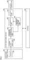
- Fig. 1 is a diagram representing a configuration example of a general state-monitoring system.
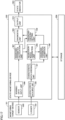
- Fig. 2 is a diagram representing a configuration example of a state-monitoring system according to Embodiment 1.
- the general state-monitoring system includes a monitoring target device 901, a state-monitoring device 902, a state indicator 903, and a storage 904.
- the monitoring target device 901 includes a sensor 905.
- the state-monitoring device 902 includes a sensing-data input unit 906, a diagnosis-parameter calculation unit 907, a diagnostic unit 908, a diagnosis-criteria setting unit 909, and an output unit 910.
- the state-monitoring system includes a monitoring target device 101, a state-monitoring device 102, a state indicator 903, and a storage 904.
- the monitoring target device 101 is the same as the monitoring target device 901 except that the monitoring target device 101 further includes a logger 103.
- the state-monitoring device 102 is the same as the state-monitoring device 902 except that the state-monitoring device 102 further includes a characteristic-data input unit 104, a regression-model generation unit 105, and a diagnosis-parameter estimation unit 106.
- an adjustment period can be reduced, while maintaining the diagnostic accuracy, by exploiting the information from the logger 103 which is not the case for the general state-monitoring system.
- the monitoring target device 101 is a target device to be monitored with respect to its state and diagnosed by the state-monitoring device 102.
- the monitoring target device 101 is, for example, wind power generation equipment, a production facility, or a machine tool.
- the sensor 905 is mounted on the monitoring target device 101.
- the sensor 905 measures physical quantities of the monitoring target device 101, such as the acceleration, the temperature, and the current.
- the sensor 905 is, for example, an acceleration sensor, a temperature sensor, or a proximity sensor.
- the storage 904 saves the data input to the state-monitoring device 102, for example.
- the storage 904 is, for example, a nonvolatile memory built in the state-monitoring device 102, or a server connected to the state-monitoring device 102 through the Internet.
- the state indicator 903 shows a diagnostic result provided by the state-monitoring device 102.
- the state indicator 903 is, for example, an indicator panel (an indicator light) mounted on the monitoring target device 101.
- the logger 103 is equipment or a medium holding characteristic data of the monitoring target device 101.
- the logger 103 is not necessary built in the monitoring target device 101.
- the logger 103 is, for example, a control device (such as a memory of a programmable logic controller (PLC) or a supervisory control and data acquisition (SCADA)), or any other state-monitoring device.
- PLC programmable logic controller
- SCADA supervisory control and data acquisition
- Fig. 3 is a diagram representing state transitions of the state-monitoring system according to Embodiment 1.
- the state-monitoring system has three states.
- a un-setup state refers to a state in which the state-monitoring device 102 is not set up and the state-monitoring device 102 and the monitoring target device 101 are not connected together.
- An adjusting state refers to a state in which the state-monitoring device 102 and the monitoring target device 101 are connected together, and the state-monitoring device 102 collects sensing data and characteristic data for the monitoring target device 101, and sets diagnosis criteria. In the adjusting state, the monitoring target device 101 is not diagnosed.
- An operating state refers to a state in which the state-monitoring device 102 and the monitoring target device 101 are connected together, the state-monitoring device 102 collects the sensing data for the monitoring target device 101, and the monitoring target device 101 is diagnosed based on the set diagnosis criteria.
- the set up refers to a state in which the state-monitoring device 102 is set up and the state-monitoring device 102 and the monitoring target device 101 are connected together. As being set up, the state-monitoring device 102 transitions from the un-setup state to the adjusting state.
- Remove refers to disconnecting and removing the state-monitoring device 102 from the monitoring target device 101. This causes the state-monitoring device 102 to transition from the adjusting state or the operating state to the un-setup state.
- the state-monitoring device 102 transitions from the adjusting state to the operating state.
- the state change refers to a situation in which there are changes in the state-monitoring device 102 and its surrounding components, and the diagnosis criteria are thus rendered unsuitable.
- the state change refers to, for example, maintenance of the monitoring target device 101 or exchange of the sensor.
- the state change causes the state-monitoring device 102 to transition from the operating state to the adjusting state.
- a time period in which the state-monitoring device 102 is in the un-setup state will be referred to as a first time period
- a time period in which the state-monitoring device 102 is in the adjusting state will be referred to as a second time period
- a time period in which the state-monitoring device 102 is in the operating state will be referred to as a third time period.
- the first time period, the second time period, and the third time period are set for the state-monitoring device 102, where the first time period is a time period before the monitoring target device 101 is connected to the state-monitoring device 102, the second time period is a preliminary period, after the monitoring target device 101 is connected to the state-monitoring device 102, for diagnosing abnormality of the monitoring target device 101, and the third time period is a time period, after the monitoring target device 101 is connected to the state-monitoring device 102, during which the state-monitoring device 102 diagnoses abnormality of the monitoring target device 101.
- the state-monitoring device 102 is allowed to quickly transition to the operating state by reducing the time period (the second time period) during which the state-monitoring device 102 is in the adjusting state.
- the sensing-data input unit 906 obtains the sensing data representing the state of the monitoring target device 101, from the sensor 905 included in the monitoring target device 101.
- the diagnosis-parameter calculation unit 907 calculates diagnosis parameters in the second time period (the adjustment period) and the third time period (the operational period).
- the characteristic-data input unit 104 obtains, from the logger 103 included in the monitoring target device 101, the characteristic data representing characteristics of the monitoring target device during the first time period (a not-yet-setup period) and the second time period (the adjustment period).
- the diagnosis-parameter estimation unit 106 estimates a diagnosis parameter in the first time period (the not-yet-setup period), which corresponds to the characteristic data in the first time period (the not-yet-setup period).
- the diagnosis-criteria setting unit 109 sets the diagnosis criteria.
- the diagnostic unit 908 diagnoses the abnormality of the monitoring target device 101, based on the diagnosis parameter in the third time period (the operational period) and the diagnosis criteria set by the diagnosis-criteria setting unit 109.
- the output unit 910 outputs a diagnostic result made by 908.
- Fig. 4 is a diagram showing exploiting of data in the general state-monitoring system versus exploiting of data in the state-monitoring system according to the present embodiment.
- the underlying data used by the diagnosis-criteria setting unit 909 to set the diagnosis criteria is the diagnosis parameter that is calculated based on the sensing data output from the sensor 905 in the second time period (the adjustment period).
- the underlying data used by the diagnosis-criteria setting unit 109 to set the diagnosis criteria is the diagnosis parameter calculated based on the sensing data output from the sensor 905 in the second time period (the adjustment period) and the diagnosis parameter in the first time period (the not-yet-setup period) estimated from the characteristic data in the first time period (the not-yet-setup period).
- the adjustment procedure performed by the general state-monitoring system uses only the diagnosis parameter calculated based on the sensing data output from the sensor 905 in the adjustment period, and thus has the following problems.
- the above problems can be solved by adding to the underlying data the diagnosis parameter in the not-yet-setup period estimated from the characteristic data held by the logger 103 during the not-yet-setup period.
- the present embodiment even if there are a small number of diagnosis parameters calculated based on the sensing data output from the sensor 905 during the adjustment period, sufficient amount of underlying data can be the ensured by adding to the underlying data the estimated diagnosis parameter in the not-yet-setup period. This allows correct diagnosis criteria to be set in a short adjustment period.
- the skewness of the underlying data can be reduced by estimating the diagnosis parameter in the not-yet-setup period and adding it to the underlying data. This allows correct diagnosis criteria to be set.
- the regression model if the regression model is accurate, sufficient amount of diagnosis parameters can be estimated from the characteristic data, accumulated in the logger, and added to the underlying data. This allows the adjustment period to be ended at an appropriate time by evaluating the performance of the regression model.
- Fig. 5 is a flowchart representing process steps performed by the general state-monitoring system in the adjusting state.
- Fig. 6 is a flowchart representing process steps performed by the state-monitoring system according to Embodiment 1 in the adjusting state.
- the state-monitoring system can transition to the not-yet-setup state at any time during the adjusting state in response to the removal, which is therefore not described in these flowcharts.
- the process steps performed by the general state-monitoring system in the adjusting state include steps S101, S102, and S 106.
- the process steps performed by the state-monitoring system according to the present embodiment in the adjusting state include steps S101 through S 106.
- the sensing-data input unit 906 collects the sensing data representing the state of the monitoring target device 101 output from the sensor 905 mounted on the monitoring target device 101 in the adjustment period (measurement of data).
- the sensing data obtained by the sensor 905 is, for example, data from an acceleration sensor, a current sensor, a volmeter, a color sensor, an orientation sensor, a wind-velocity sensor, a flow sensor, a pressure sensor, or a proximity sensor.
- the diagnosis-parameter calculation unit 907 calculates the diagnosis parameter in the adjustment period, based on the sensing data obtained during the adjustment period.
- the diagnosis parameter is not only the data detected by the sensor 905 as is, but also statistics of the data detected by the sensor 905, such as a root mean square, a modulation value, an average, a median, a kurtosis, and a skewness, an amount of electric power that is determined by multiplying the current value and the rated voltage, time differences between inputs of proximity sensors mounted at multiple locations of a conveyer included in the monitoring target device 101, and physical quantities such as the speed of an conveyed article determined from the distances between these proximity sensors.
- the characteristic-data input unit 104 obtains, from the logger 103 included in the monitoring target device 101, the characteristic data representing the characteristics of the monitoring target device 101 in the not-yet-setup period and in the adjustment period.
- the characteristic data of the monitoring target device 101 include the pressure, the temperature, the rotational speed, the current value, the flow rate, or the maintenance information of the monitoring target device.
- the monitoring target device 101 is wind power generation equipment
- examples of the characteristic data include the wind direction, the wind velocity, the weather, or the air pressure.
- the monitoring target device 101 is a machine tool
- examples of the characteristic data include the type of a machined work, the type of machining process, the tool information, or the type of material.
- the regression-model generation unit 105 uses the characteristic data in the adjustment period and the diagnosis parameter in the adjustment period, the regression-model generation unit 105 generates the regression model representing a relationship between the characteristic data and the diagnosis parameter.
- the regression model is various neural networks such as a simple regression model (single regression), multiple regression model (multiple regression), a feedforward neural network, or a radial basis function (RBF) network.
- step S105 using the regression model, the diagnosis-parameter estimation unit 106 estimates the diagnosis parameter in the not-yet-setup period, which corresponds to the characteristic data in the not-yet-setup period.
- the diagnosis-criteria setting unit 109 creates the diagnosis criteria from the underlying data consisting of the diagnosis parameter in the not-yet-setup period and the diagnosis parameter in the adjustment period.
- the diagnosis criteria are a threshold or an adjusted neural network.
- the threshold is, for example, the average of the underlying data multiplied by a constant multiple (e.g., 3) of the standard deviation of the underlying data.
- monitoring target device 101 is the wind power generation equipment
- a vibration sensor is mounted on a step-up gearbox in the wind power generation equipment.
- step S101 in the adjustment period, the sensing-data input unit 906 collects vibration data representing the vibrating state of the monitoring target device 101, which is output from the vibration sensor mounted on the monitoring target device 101.
- step S102 the diagnosis-parameter calculation unit 907 calculates, as a diagnosis parameter, a vibration root mean square in the adjustment period from the vibration data obtained in the adjustment period.
- step S103 as the characteristic data of the wind power generation equipment, the characteristic-data input unit 104 obtains, from the logger 103 included in the monitoring target device 101, the main shaft's rotational speeds in the not-yet-setup period and the adjustment period which are saved in a control device of the wind power generation equipment.
- step S104 using the characteristic data (the main shaft's rotational speed) in the adjustment period and the diagnosis parameter (the vibration root mean square) in the adjustment period, the regression-model generation unit 105 generates a second-order polynomial regression model representing the relationship between the characteristic data and the diagnosis parameter.
- step S105 using the second-order polynomial regression model, the diagnosis-parameter estimation unit 106 estimates the diagnosis parameter (the vibration root mean square) in the not-yet-setup period, which corresponds to the characteristic data (the main shaft's rotational speed) in the not-yet-setup period.
- diagnosis parameter the vibration root mean square
- the diagnosis-criteria setting unit 909 creates diagnosis criteria, consisting of a first threshold Th1 and a second threshold Th2, from the underlying data consisting of the vibration root mean square in the not-yet-setup period and the vibration root mean square in the adjustment period.
- Fig. 7 is a diagram representing transition of the diagnosis parameter after the state-monitoring device is set up.
- Fig. 8 is a diagram representing the data of the main shaft's rotational speed of the wind power generation equipment saved in SCADA.
- the revolutions per minute (rpm) of the main shaft of a wind mill continues low, and the vibration root mean square (the diagnosis parameter) is measured only when the main shaft rpm is low. Due to this, with a general method, correct diagnosis criteria cannot be set without the vibration sensor measuring the vibration data over a month after the state-monitoring device is set up.
- Fig. 9 is a diagram representing changes in diagnosis parameter during the adjustment period, according to Embodiment 1. Using the one month (August 1st to September 1st) after the state-monitoring device is set up as the adjustment period, the vibration root mean square, which is the diagnosis parameter, is calculated from the sensing data obtained by the sensor 905 in this adjustment period.
- Fig. 10 is a diagram representing the second-order polynomial regression model according to Embodiment 1.
- the second-order polynomial regression model is generated for estimating the vibration root mean square (the diagnosis parameter) from the main shaft's rotational speed (the characteristic data). Since the main shaft rpm is low during the adjustment period, the second-order polynomial regression model is generated from the low main shaft rpm and its corresponding vibration root mean square.
- Fig. 11 is a diagram representing the estimated diagnosis parameter.
- a vibration root mean square (the diagnosis parameter) corresponding to the main shaft rpm (the characteristic data) of the not-yet-setup period is obtained.
- Fig. 12 is a diagram representing an example of the underlying data.
- the underlying data consists of: the vibration root mean square (the diagnosis parameter) that is calculated from the sensing data obtained by the vibration sensor during the adjustment period; and the vibration root mean square (the diagnosis parameter) estimated during the not-yet-setup period, using the second-order polynomial regression model, from the main shaft rpm (the characteristic data).
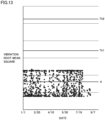
- Fig. 13 is a diagram representing an example of the underlying data and the diagnosis criteria.
- the first threshold Th1 and the second threshold Th2 which are the diagnosis criteria, are set from the underlying data.
- the diagnosis criteria can be set and the state-monitoring device 102 can be caused to transition to the operating state.
- Fig. 14 is a diagram representing an example of the underlying data and the diagnosis parameter in the operational period.
- the operational period starts on September 1st.
- the vibration root mean square (the diagnosis parameter) obtained from the sensing data by the vibration sensor is compared with the first threshold Th1 and the second threshold Th2, and the monitoring target device 101 is thereby diagnosed.
- Fig. 15 is a flowchart representing process steps performed by the state-monitoring system according to Embodiment 1 in the operating state.
- transition to the not-yet-setup state caused by the removal, and the transition to the adjusting state due to the state change can occur at any time during the operating state, which is therefore not described in the flowchart. Furthermore, the operating state continues as long as the remove or the state change does not occur. Thus, the end of the flowchart is not described either.
- step S301 in the operational period, the sensing-data input unit 906 collects the sensing data representing the state of the monitoring target device 101 output from the sensor 905 mounted on the monitoring target device 101.
- step S302 the diagnosis-parameter calculation unit 907 calculates the diagnosis parameter in the operational period, based on the sensing data obtained in the operational period.
- step S303 using the diagnosis criteria set in the adjustment period, the diagnostic unit 908 analyzes the diagnosis parameter calculated in step S302, thereby diagnosing the state of the monitoring target device 101.
- step S304 the output unit 910 outputs a diagnostic result to the state indicator 903.
- Examples of the method of diagnosis made by the diagnostic unit 908 include a method of diagnosis of the state of the monitoring target device 101 by comparing the diagnosis parameter with a threshold, a method of diagnosis by clusters categorized by clustering the diagnosis parameter, and a method in which the diagnosis parameter is input to an adjusted neural network and the output from the neural network is used as a diagnostic result.
- diagnosis parameter is compared with a threshold and the state of the monitoring target device 101 is diagnosed per case.
- Fig. 16 is a flowchart showing a procedure for diagnosis made by the state-monitoring system according to Embodiment 1.
- step S501 if the diagnosis parameter (x) is less than or equal to the first threshold (Th1), the process proceeds to step S503. If the diagnosis parameter (x) is greater than the first threshold (Th1), the process proceeds to step S502.
- step S502 if the diagnosis parameter (x) is less than or equal to the second threshold (Th2), the process proceeds to step S504. If the diagnosis parameter (x) is greater than the second threshold (Th2), the process proceeds to step S505.
- step S503 the diagnostic unit 908 determines that the monitoring target device 101 is in a "normal state.” Being "normal” refers to a state in which the monitoring target device 101 has no abnormality.
- step S504 the diagnostic unit 908 determines that the monitoring target device 101 is in an "inspection required state."
- the "inspection required state” refers to a state in which the monitoring target device 101 has some indication of abnormality and inspection is required.
- step S505 the diagnostic unit 908 determines that the monitoring target device 101 is in a "pause required state."
- the "pause required state” refers to a state in which the monitoring target device may be damaged if the monitoring target device 101 continues to operate any further.
- the diagnostic accuracy can be maintained even if the adjustment period is reduced.
- the reduction of the adjustment period allows reduction of a time lag from the setup of the state-monitoring device to the beginning of the diagnosis, thereby reducing the likelihood that an abnormality event is missed because it occurs before the diagnosis begins.
- Fig. 17 is a diagram representing a configuration example of a state-monitoring system according to Embodiment 2.
- the state-monitoring system according to Embodiment 2 includes a characteristic data selection unit 107, in addition to the components of the state-monitoring system according to Embodiment 1, and includes a regression-model generation unit 205, instead of the regression-model generation unit 105.
- the characteristic data selection unit 107 selects the characteristic data whose correlation coefficient with the diagnosis parameter in the second time period is greater than or equal to a threshold, from among the characteristic data items in multiple second time periods. For example, suppose that, where the diagnosis parameter is the vibration root mean square, the main shaft's rotational speed, the wind direction, and the wind volume are obtained as the characteristic data.
- the characteristic data selection unit 107 selects the main shaft's rotational speed if the correlation coefficient of the main shaft's rotational speed in the second time period with the vibration root mean square in the second time period is greater than or equal to the threshold, the correlation coefficient of the wind direction in the second time period with the vibration root mean square in the second time period is less than the threshold, and the correlation coefficient of the wind volume in the second time period with the vibration root mean square in the second time period is less than the threshold.
- the regression-model generation unit 205 uses the selected characteristic data to generate the regression model.
- Fig. 18 is a flowchart representing process steps performed by the state-monitoring system according to Embodiment 2 in the adjusting state.
- the flowchart according to Embodiment 2 of Fig. 18 is the same as the flowchart according to Embodiment 1 of Fig. 6 , except that the flowchart according to Embodiment 2 of Fig. 18 includes step S201.
- step S201 the characteristic data selection unit 107 selects the characteristic data whose correlation coefficient with the diagnosis parameter in the second time period (the adjustment period) is greater than or equal to the threshold from among the characteristic data items in multiple second time periods (adjustment periods), and outputs the characteristic data to the regression-model generation unit 205.
- a precise regression model can be created.
- Fig. 19 is a diagram representing a configuration example of a state-monitoring system according to Embodiment 3.
- the state-monitoring system according to Embodiment 3 includes a regression model evaluation unit 303, in addition to the components of the state-monitoring system according to Embodiment 2.
- the regression model evaluation unit 303 determines a score of the regression model, based on metrics.
- the metrics are, for example, accuracy, precision, recall, F-stop, mean-squared error, root mean square error, or coefficient of determination.
- the acquisition of the sensing data by the sensing-data input unit 906, the calculation of the diagnosis parameter by the diagnosis-parameter calculation unit 907, the acquisition of the characteristic data by the characteristic-data input unit 104, and the generation of the regression model by the regression-model generation unit 205 are repeated until the score of the regression model reaches a predetermined value.
- Fig. 20 is a flowchart representing process steps performed by the state-monitoring system according to Embodiment 3 in the adjusting state.
- the flowchart according to Embodiment 3 of Fig. 20 is the same as the flowchart according to Embodiment 2 of Fig. 18 , except that the flowchart according to Embodiment 3 of Fig. 20 includes step S401 following step S105.
- step S401 the regression model evaluation unit 303 determines the score of the regression model, based on the metrics.
- step S105 If the score of the regression model is greater than or equal to the predetermined value, the process proceeds to step S101.
- the time to end the adjustment period can be appropriately determined by evaluating the performance of the regression model. By appropriately determining the time to end the adjustment period, the risk of extending the adjustment period longer than necessary, and the risk of misdiagnosis caused by reducing the adjustment period shorter than a necessary length, can be reduced.
- a state-monitoring system has a function of modifying the diagnosis criteria in the operational period.
- Fig. 21 is a flowchart representing process steps performed by the state-monitoring system according to Embodiment 4 in the operating state.
- step S601 in the operational period, the sensing-data input unit 906 collects the sensing data representing the state of the monitoring target device 101 output from the sensor 905 mounted on the monitoring target device 101.
- step S602 the diagnosis-parameter calculation unit 907 calculates the diagnosis parameter in the operational period, based on the sensing data in the operational period.
- step S603 using the diagnosis criteria set in the adjustment period or the diagnosis criteria modified in the operational period, the diagnostic unit 908 analyzes the diagnosis parameter calculated in step S602, thereby diagnosing the state of the monitoring target device 101.
- step S604 the output unit 910 outputs a diagnostic result to the state indicator 903.
- step S605 the characteristic-data input unit 104 obtains the characteristic data representing the characteristics of the monitoring target device 101 in the operational period, from the logger 103 included in the monitoring target device 101.
- step S606 using the characteristic data in the adjustment period and the operational period and the diagnosis parameters in the adjustment period and the operational period, the regression-model generation unit 205 modifies the regression model representing the relationship between the characteristic data and the diagnosis parameter.
- step S607 using the modified regression model, the diagnosis-parameter estimation unit 106 re-estimates the diagnosis parameter in the not-yet-setup period, which corresponds to the characteristic data in the not-yet-setup period.
- step S608 the diagnosis-criteria setting unit 109 modifies the diagnosis criteria from the underlying data consisting of: the diagnosis parameter in the not-yet-setup period; the diagnosis parameter in the adjustment period; and the diagnosis parameter in the operational period.
Landscapes
- Physics & Mathematics (AREA)
- Engineering & Computer Science (AREA)
- General Physics & Mathematics (AREA)
- Automation & Control Theory (AREA)
- Artificial Intelligence (AREA)
- Evolutionary Computation (AREA)
- Mathematical Physics (AREA)
- Testing And Monitoring For Control Systems (AREA)
Applications Claiming Priority (2)
| Application Number | Priority Date | Filing Date | Title |
|---|---|---|---|
| JP2020165518A JP7471983B2 (ja) | 2020-09-30 | 2020-09-30 | 状態監視装置および状態監視方法 |
| PCT/JP2021/035274 WO2022071189A1 (ja) | 2020-09-30 | 2021-09-27 | 状態監視装置および状態監視方法 |
Publications (3)
| Publication Number | Publication Date |
|---|---|
| EP4224263A1 true EP4224263A1 (de) | 2023-08-09 |
| EP4224263A4 EP4224263A4 (de) | 2024-10-30 |
| EP4224263B1 EP4224263B1 (de) | 2025-09-24 |
Family
ID=80949155
Family Applications (1)
| Application Number | Title | Priority Date | Filing Date |
|---|---|---|---|
| EP21875491.9A Active EP4224263B1 (de) | 2020-09-30 | 2021-09-27 | Zustandsüberwachungsvorrichtung und zustandsüberwachungsverfahren |
Country Status (5)
| Country | Link |
|---|---|
| US (1) | US20230367283A1 (de) |
| EP (1) | EP4224263B1 (de) |
| JP (1) | JP7471983B2 (de) |
| CN (1) | CN116075791B (de) |
| WO (1) | WO2022071189A1 (de) |
Families Citing this family (1)
| Publication number | Priority date | Publication date | Assignee | Title |
|---|---|---|---|---|
| CN119472563B (zh) * | 2025-01-14 | 2025-04-15 | 杭州赛微电机有限公司 | 电机装配生产线的运转监控系统及方法 |
Family Cites Families (16)
| Publication number | Priority date | Publication date | Assignee | Title |
|---|---|---|---|---|
| JP2004133553A (ja) * | 2002-10-08 | 2004-04-30 | Toshiba Corp | 設備診断装置 |
| JP2008230781A (ja) * | 2007-03-20 | 2008-10-02 | Toshiba Elevator Co Ltd | エレベータの診断システム |
| US8301333B2 (en) * | 2010-03-24 | 2012-10-30 | GM Global Technology Operations LLC | Event-driven fault diagnosis framework for automotive systems |
| US9824060B2 (en) * | 2010-07-23 | 2017-11-21 | Polyvalor, Limited Partnership | Tool and method for fault detection of devices by condition based maintenance |
| WO2013113379A1 (en) * | 2012-02-01 | 2013-08-08 | Abb Research Ltd | Monitoring of primary devices in a power system |
| CN104160145B (zh) * | 2012-03-08 | 2017-06-13 | Ntn株式会社 | 状态监视系统 |
| JP5917956B2 (ja) * | 2012-03-08 | 2016-05-18 | Ntn株式会社 | 状態監視システム |
| JP5949135B2 (ja) * | 2012-05-18 | 2016-07-06 | 株式会社Ihi | 異常診断方法及び異常診断装置 |
| EP3074824B8 (de) * | 2013-11-27 | 2019-08-14 | Adept AI Systems Inc. | Verfahren und system für auf künstlicher intelligenz und modell basierter steuerung dynamischer prozesse mittels probabilistischer agenten |
| JP6116466B2 (ja) * | 2013-11-28 | 2017-04-19 | 株式会社日立製作所 | プラントの診断装置及び診断方法 |
| CN103761372B (zh) * | 2014-01-06 | 2018-02-02 | 上海海事大学 | 一种基于主元分析与多分类相关向量机的多电平逆变器故障诊断策略 |
| JP6374234B2 (ja) * | 2014-06-24 | 2018-08-15 | Ntn株式会社 | 状態監視システム及びそれを備えた風力発電システム |
| JP5943357B2 (ja) * | 2014-09-17 | 2016-07-05 | インターナショナル・ビジネス・マシーンズ・コーポレーションInternational Business Machines Corporation | 検出装置、検出方法、およびプログラム |
| WO2017051866A1 (ja) * | 2015-09-25 | 2017-03-30 | Ntn株式会社 | リンク作動装置の診断装置 |
| JP6714962B2 (ja) * | 2016-03-29 | 2020-07-01 | 一般財団法人電力中央研究所 | 太陽光発電設備の異常診断方法、異常診断装置、及び異常診断プログラム |
| JP7113668B2 (ja) * | 2018-06-08 | 2022-08-05 | Ntn株式会社 | 状態監視システム |
-
2020
- 2020-09-30 JP JP2020165518A patent/JP7471983B2/ja active Active
-
2021
- 2021-09-27 CN CN202180064032.6A patent/CN116075791B/zh active Active
- 2021-09-27 EP EP21875491.9A patent/EP4224263B1/de active Active
- 2021-09-27 WO PCT/JP2021/035274 patent/WO2022071189A1/ja not_active Ceased
- 2021-09-27 US US18/026,099 patent/US20230367283A1/en active Pending
Also Published As
| Publication number | Publication date |
|---|---|
| CN116075791A (zh) | 2023-05-05 |
| JP2022057324A (ja) | 2022-04-11 |
| JP7471983B2 (ja) | 2024-04-22 |
| CN116075791B (zh) | 2025-11-07 |
| EP4224263B1 (de) | 2025-09-24 |
| US20230367283A1 (en) | 2023-11-16 |
| WO2022071189A1 (ja) | 2022-04-07 |
| EP4224263A4 (de) | 2024-10-30 |
Similar Documents
| Publication | Publication Date | Title |
|---|---|---|
| US11614728B2 (en) | Machine tool management system that obtains a next maintenance period from a maintenance period model and a refinement algorithm | |
| CN110991666B (zh) | 故障检测方法、模型的训练方法、装置、设备及存储介质 | |
| EP3638900B1 (de) | Unabhängiges überwachungssystem für eine windturbine | |
| US11521105B2 (en) | Machine learning device and machine learning method for learning fault prediction of main shaft or motor which drives main shaft, and fault prediction device and fault prediction system including machine learning device | |
| EP1955830A1 (de) | Verfahren und Steuersystem zur Überwachung des Zustands eines Industrieroboters | |
| EP3835750B1 (de) | System zur diagnose von anomalien und verfahren zur diagnose von anomalien | |
| TWI533589B (zh) | 電動機控制裝置 | |
| JP2004240642A (ja) | プラント機器の保守支援装置 | |
| CN119476968B (zh) | 基于数据分析的基建线路高风险作业实时监测系统 | |
| US7249287B2 (en) | Methods and apparatus for providing alarm notification | |
| CN111989198B (zh) | 异常检测装置以及异常检测方法 | |
| EP4224263B1 (de) | Zustandsüberwachungsvorrichtung und zustandsüberwachungsverfahren | |
| EP0691631A1 (de) | Dauerzustandssensor | |
| CN118013468B (zh) | 一种风电机组部件健康度监测方法、装置、设备及介质 | |
| EP3404502B1 (de) | Zustandsbasierte instandhaltung einer vorrichtung | |
| EP3936957B1 (de) | Fehlerbasiertes verfahren zur berechnung einer restlebensdauer einer vorrichtung | |
| CN113312758B (zh) | 风力发电机组的健康状态评估方法和装置 | |
| JP7131611B2 (ja) | 異常判定装置及び異常判定方法 | |
| CN112629710A (zh) | 一种发动机温度传感器的智能自诊断方法 | |
| US11339763B2 (en) | Method for windmill farm monitoring | |
| US20250242713A1 (en) | Startup condition monitoring system for a machine | |
| JPH10301619A (ja) | 燃料電池発電プラント診断装置 | |
| CN119247412A (zh) | 一种北斗定位设备的故障检测方法、装置、终端设备和存储介质 | |
| WO2020054725A1 (ja) | 診断装置及び診断方法 | |
| CN119103009A (zh) | 一种风力发电机远程监控系统 |
Legal Events
| Date | Code | Title | Description |
|---|---|---|---|
| STAA | Information on the status of an ep patent application or granted ep patent |
Free format text: STATUS: THE INTERNATIONAL PUBLICATION HAS BEEN MADE |
|
| PUAI | Public reference made under article 153(3) epc to a published international application that has entered the european phase |
Free format text: ORIGINAL CODE: 0009012 |
|
| STAA | Information on the status of an ep patent application or granted ep patent |
Free format text: STATUS: REQUEST FOR EXAMINATION WAS MADE |
|
| 17P | Request for examination filed |
Effective date: 20230315 |
|
| AK | Designated contracting states |
Kind code of ref document: A1 Designated state(s): AL AT BE BG CH CY CZ DE DK EE ES FI FR GB GR HR HU IE IS IT LI LT LU LV MC MK MT NL NO PL PT RO RS SE SI SK SM TR |
|
| DAV | Request for validation of the european patent (deleted) | ||
| DAX | Request for extension of the european patent (deleted) | ||
| A4 | Supplementary search report drawn up and despatched |
Effective date: 20240926 |
|
| RIC1 | Information provided on ipc code assigned before grant |
Ipc: G05B 23/02 20060101AFI20240920BHEP |
|
| GRAP | Despatch of communication of intention to grant a patent |
Free format text: ORIGINAL CODE: EPIDOSNIGR1 |
|
| STAA | Information on the status of an ep patent application or granted ep patent |
Free format text: STATUS: GRANT OF PATENT IS INTENDED |
|
| INTG | Intention to grant announced |
Effective date: 20250423 |
|
| GRAS | Grant fee paid |
Free format text: ORIGINAL CODE: EPIDOSNIGR3 |
|
| GRAA | (expected) grant |
Free format text: ORIGINAL CODE: 0009210 |
|
| STAA | Information on the status of an ep patent application or granted ep patent |
Free format text: STATUS: THE PATENT HAS BEEN GRANTED |
|
| AK | Designated contracting states |
Kind code of ref document: B1 Designated state(s): AL AT BE BG CH CY CZ DE DK EE ES FI FR GB GR HR HU IE IS IT LI LT LU LV MC MK MT NL NO PL PT RO RS SE SI SK SM TR |
|
| REG | Reference to a national code |
Ref country code: GB Ref legal event code: FG4D |
|
| REG | Reference to a national code |
Ref country code: CH Ref legal event code: EP |
|
| REG | Reference to a national code |
Ref country code: DE Ref legal event code: R096 Ref document number: 602021039306 Country of ref document: DE |
|
| PGFP | Annual fee paid to national office [announced via postgrant information from national office to epo] |
Ref country code: AT Payment date: 20251020 Year of fee payment: 5 |
|
| REG | Reference to a national code |
Ref country code: IE Ref legal event code: FG4D |
|
| PGFP | Annual fee paid to national office [announced via postgrant information from national office to epo] |
Ref country code: DE Payment date: 20251127 Year of fee payment: 5 |
|
| PG25 | Lapsed in a contracting state [announced via postgrant information from national office to epo] |
Ref country code: NO Free format text: LAPSE BECAUSE OF FAILURE TO SUBMIT A TRANSLATION OF THE DESCRIPTION OR TO PAY THE FEE WITHIN THE PRESCRIBED TIME-LIMIT Effective date: 20251224 |
|
| REG | Reference to a national code |
Ref country code: LT Ref legal event code: MG9D |
|
| PG25 | Lapsed in a contracting state [announced via postgrant information from national office to epo] |
Ref country code: FI Free format text: LAPSE BECAUSE OF FAILURE TO SUBMIT A TRANSLATION OF THE DESCRIPTION OR TO PAY THE FEE WITHIN THE PRESCRIBED TIME-LIMIT Effective date: 20250924 |
|
| PG25 | Lapsed in a contracting state [announced via postgrant information from national office to epo] |
Ref country code: HR Free format text: LAPSE BECAUSE OF FAILURE TO SUBMIT A TRANSLATION OF THE DESCRIPTION OR TO PAY THE FEE WITHIN THE PRESCRIBED TIME-LIMIT Effective date: 20250924 |
|
| PGFP | Annual fee paid to national office [announced via postgrant information from national office to epo] |
Ref country code: FR Payment date: 20251103 Year of fee payment: 5 |
|
| PG25 | Lapsed in a contracting state [announced via postgrant information from national office to epo] |
Ref country code: GR Free format text: LAPSE BECAUSE OF FAILURE TO SUBMIT A TRANSLATION OF THE DESCRIPTION OR TO PAY THE FEE WITHIN THE PRESCRIBED TIME-LIMIT Effective date: 20251225 |
|
| PG25 | Lapsed in a contracting state [announced via postgrant information from national office to epo] |
Ref country code: SE Free format text: LAPSE BECAUSE OF FAILURE TO SUBMIT A TRANSLATION OF THE DESCRIPTION OR TO PAY THE FEE WITHIN THE PRESCRIBED TIME-LIMIT Effective date: 20250924 |
|
| PG25 | Lapsed in a contracting state [announced via postgrant information from national office to epo] |
Ref country code: LV Free format text: LAPSE BECAUSE OF FAILURE TO SUBMIT A TRANSLATION OF THE DESCRIPTION OR TO PAY THE FEE WITHIN THE PRESCRIBED TIME-LIMIT Effective date: 20250924 |
|
| PG25 | Lapsed in a contracting state [announced via postgrant information from national office to epo] |
Ref country code: BG Free format text: LAPSE BECAUSE OF FAILURE TO SUBMIT A TRANSLATION OF THE DESCRIPTION OR TO PAY THE FEE WITHIN THE PRESCRIBED TIME-LIMIT Effective date: 20250924 |
|
| PG25 | Lapsed in a contracting state [announced via postgrant information from national office to epo] |
Ref country code: RS Free format text: LAPSE BECAUSE OF FAILURE TO SUBMIT A TRANSLATION OF THE DESCRIPTION OR TO PAY THE FEE WITHIN THE PRESCRIBED TIME-LIMIT Effective date: 20251224 |
|
| REG | Reference to a national code |
Ref country code: NL Ref legal event code: MP Effective date: 20250924 |
|
| PG25 | Lapsed in a contracting state [announced via postgrant information from national office to epo] |
Ref country code: NL Free format text: LAPSE BECAUSE OF FAILURE TO SUBMIT A TRANSLATION OF THE DESCRIPTION OR TO PAY THE FEE WITHIN THE PRESCRIBED TIME-LIMIT Effective date: 20250924 |
|
| REG | Reference to a national code |
Ref country code: AT Ref legal event code: MK05 Ref document number: 1840804 Country of ref document: AT Kind code of ref document: T Effective date: 20250924 |
|
| PG25 | Lapsed in a contracting state [announced via postgrant information from national office to epo] |
Ref country code: SM Free format text: LAPSE BECAUSE OF FAILURE TO SUBMIT A TRANSLATION OF THE DESCRIPTION OR TO PAY THE FEE WITHIN THE PRESCRIBED TIME-LIMIT Effective date: 20250924 |
|
| PG25 | Lapsed in a contracting state [announced via postgrant information from national office to epo] |
Ref country code: ES Free format text: LAPSE BECAUSE OF FAILURE TO SUBMIT A TRANSLATION OF THE DESCRIPTION OR TO PAY THE FEE WITHIN THE PRESCRIBED TIME-LIMIT Effective date: 20250924 |
|
| PG25 | Lapsed in a contracting state [announced via postgrant information from national office to epo] |
Ref country code: AT Free format text: LAPSE BECAUSE OF FAILURE TO SUBMIT A TRANSLATION OF THE DESCRIPTION OR TO PAY THE FEE WITHIN THE PRESCRIBED TIME-LIMIT Effective date: 20250924 |
|
| PG25 | Lapsed in a contracting state [announced via postgrant information from national office to epo] |
Ref country code: RO Free format text: LAPSE BECAUSE OF FAILURE TO SUBMIT A TRANSLATION OF THE DESCRIPTION OR TO PAY THE FEE WITHIN THE PRESCRIBED TIME-LIMIT Effective date: 20250924 Ref country code: IT Free format text: LAPSE BECAUSE OF FAILURE TO SUBMIT A TRANSLATION OF THE DESCRIPTION OR TO PAY THE FEE WITHIN THE PRESCRIBED TIME-LIMIT Effective date: 20250924 |
|
| PG25 | Lapsed in a contracting state [announced via postgrant information from national office to epo] |
Ref country code: IS Free format text: LAPSE BECAUSE OF FAILURE TO SUBMIT A TRANSLATION OF THE DESCRIPTION OR TO PAY THE FEE WITHIN THE PRESCRIBED TIME-LIMIT Effective date: 20260124 |