EP4224634A1 - Système de mise en contact électrique d'un élément de raccordement - Google Patents
Système de mise en contact électrique d'un élément de raccordement Download PDFInfo
- Publication number
- EP4224634A1 EP4224634A1 EP22217077.1A EP22217077A EP4224634A1 EP 4224634 A1 EP4224634 A1 EP 4224634A1 EP 22217077 A EP22217077 A EP 22217077A EP 4224634 A1 EP4224634 A1 EP 4224634A1
- Authority
- EP
- European Patent Office
- Prior art keywords
- connection
- contact
- cable
- connection element
- electrical
- Prior art date
- Legal status (The legal status is an assumption and is not a legal conclusion. Google has not performed a legal analysis and makes no representation as to the accuracy of the status listed.)
- Granted
Links
Images

Classifications
-
- H—ELECTRICITY
- H01—ELECTRIC ELEMENTS
- H01R—ELECTRICALLY-CONDUCTIVE CONNECTIONS; STRUCTURAL ASSOCIATIONS OF A PLURALITY OF MUTUALLY-INSULATED ELECTRICAL CONNECTING ELEMENTS; COUPLING DEVICES; CURRENT COLLECTORS
- H01R13/00—Details of coupling devices of the kinds covered by groups H01R12/70 or H01R24/00 - H01R33/00
- H01R13/02—Contact members
-
- H—ELECTRICITY
- H01—ELECTRIC ELEMENTS
- H01R—ELECTRICALLY-CONDUCTIVE CONNECTIONS; STRUCTURAL ASSOCIATIONS OF A PLURALITY OF MUTUALLY-INSULATED ELECTRICAL CONNECTING ELEMENTS; COUPLING DEVICES; CURRENT COLLECTORS
- H01R4/00—Electrically-conductive connections between two or more conductive members in direct contact, i.e. touching one another; Means for effecting or maintaining such contact; Electrically-conductive connections having two or more spaced connecting locations for conductors and using contact members penetrating insulation
- H01R4/28—Clamped connections, spring connections
- H01R4/48—Clamped connections, spring connections utilising a spring, clip, or other resilient member
- H01R4/4809—Clamped connections, spring connections utilising a spring, clip, or other resilient member using a leaf spring to bias the conductor toward the busbar
- H01R4/48185—Clamped connections, spring connections utilising a spring, clip, or other resilient member using a leaf spring to bias the conductor toward the busbar adapted for axial insertion of a wire end
- H01R4/48275—Clamped connections, spring connections utilising a spring, clip, or other resilient member using a leaf spring to bias the conductor toward the busbar adapted for axial insertion of a wire end with an opening in the housing for insertion of a release tool
-
- F—MECHANICAL ENGINEERING; LIGHTING; HEATING; WEAPONS; BLASTING
- F21—LIGHTING
- F21S—NON-PORTABLE LIGHTING DEVICES; SYSTEMS THEREOF; VEHICLE LIGHTING DEVICES SPECIALLY ADAPTED FOR VEHICLE EXTERIORS
- F21S2/00—Systems of lighting devices, not provided for in main groups F21S4/00 - F21S10/00 or F21S19/00, e.g. of modular construction
- F21S2/005—Systems of lighting devices, not provided for in main groups F21S4/00 - F21S10/00 or F21S19/00, e.g. of modular construction of modular construction
-
- F—MECHANICAL ENGINEERING; LIGHTING; HEATING; WEAPONS; BLASTING
- F21—LIGHTING
- F21V—FUNCTIONAL FEATURES OR DETAILS OF LIGHTING DEVICES OR SYSTEMS THEREOF; STRUCTURAL COMBINATIONS OF LIGHTING DEVICES WITH OTHER ARTICLES, NOT OTHERWISE PROVIDED FOR
- F21V23/00—Arrangement of electric circuit elements in or on lighting devices
- F21V23/003—Arrangement of electric circuit elements in or on lighting devices the elements being electronics drivers or controllers for operating the light source, e.g. for a LED array
- F21V23/004—Arrangement of electric circuit elements in or on lighting devices the elements being electronics drivers or controllers for operating the light source, e.g. for a LED array arranged on a substrate, e.g. a printed circuit board
- F21V23/005—Arrangement of electric circuit elements in or on lighting devices the elements being electronics drivers or controllers for operating the light source, e.g. for a LED array arranged on a substrate, e.g. a printed circuit board the substrate is supporting also the light source
-
- F—MECHANICAL ENGINEERING; LIGHTING; HEATING; WEAPONS; BLASTING
- F21—LIGHTING
- F21V—FUNCTIONAL FEATURES OR DETAILS OF LIGHTING DEVICES OR SYSTEMS THEREOF; STRUCTURAL COMBINATIONS OF LIGHTING DEVICES WITH OTHER ARTICLES, NOT OTHERWISE PROVIDED FOR
- F21V23/00—Arrangement of electric circuit elements in or on lighting devices
- F21V23/06—Arrangement of electric circuit elements in or on lighting devices the elements being coupling devices, e.g. connectors
-
- H—ELECTRICITY
- H01—ELECTRIC ELEMENTS
- H01R—ELECTRICALLY-CONDUCTIVE CONNECTIONS; STRUCTURAL ASSOCIATIONS OF A PLURALITY OF MUTUALLY-INSULATED ELECTRICAL CONNECTING ELEMENTS; COUPLING DEVICES; CURRENT COLLECTORS
- H01R12/00—Structural associations of a plurality of mutually-insulated electrical connecting elements, specially adapted for printed circuits, e.g. printed circuit boards [PCB], flat or ribbon cables, or like generally planar structures, e.g. terminal strips, terminal blocks; Coupling devices specially adapted for printed circuits, flat or ribbon cables, or like generally planar structures; Terminals specially adapted for contact with, or insertion into, printed circuits, flat or ribbon cables, or like generally planar structures
- H01R12/50—Fixed connections
- H01R12/51—Fixed connections for rigid printed circuits or like structures
- H01R12/55—Fixed connections for rigid printed circuits or like structures characterised by the terminals
-
- H—ELECTRICITY
- H01—ELECTRIC ELEMENTS
- H01R—ELECTRICALLY-CONDUCTIVE CONNECTIONS; STRUCTURAL ASSOCIATIONS OF A PLURALITY OF MUTUALLY-INSULATED ELECTRICAL CONNECTING ELEMENTS; COUPLING DEVICES; CURRENT COLLECTORS
- H01R13/00—Details of coupling devices of the kinds covered by groups H01R12/70 or H01R24/00 - H01R33/00
- H01R13/62—Means for facilitating engagement or disengagement of coupling parts or for holding them in engagement
- H01R13/639—Additional means for holding or locking coupling parts together, after engagement, e.g. separate keylock, retainer strap
-
- H—ELECTRICITY
- H01—ELECTRIC ELEMENTS
- H01R—ELECTRICALLY-CONDUCTIVE CONNECTIONS; STRUCTURAL ASSOCIATIONS OF A PLURALITY OF MUTUALLY-INSULATED ELECTRICAL CONNECTING ELEMENTS; COUPLING DEVICES; CURRENT COLLECTORS
- H01R4/00—Electrically-conductive connections between two or more conductive members in direct contact, i.e. touching one another; Means for effecting or maintaining such contact; Electrically-conductive connections having two or more spaced connecting locations for conductors and using contact members penetrating insulation
- H01R4/28—Clamped connections, spring connections
- H01R4/48—Clamped connections, spring connections utilising a spring, clip, or other resilient member
-
- H—ELECTRICITY
- H01—ELECTRIC ELEMENTS
- H01R—ELECTRICALLY-CONDUCTIVE CONNECTIONS; STRUCTURAL ASSOCIATIONS OF A PLURALITY OF MUTUALLY-INSULATED ELECTRICAL CONNECTING ELEMENTS; COUPLING DEVICES; CURRENT COLLECTORS
- H01R4/00—Electrically-conductive connections between two or more conductive members in direct contact, i.e. touching one another; Means for effecting or maintaining such contact; Electrically-conductive connections having two or more spaced connecting locations for conductors and using contact members penetrating insulation
- H01R4/28—Clamped connections, spring connections
- H01R4/48—Clamped connections, spring connections utilising a spring, clip, or other resilient member
- H01R4/4809—Clamped connections, spring connections utilising a spring, clip, or other resilient member using a leaf spring to bias the conductor toward the busbar
- H01R4/484—Spring housing details
- H01R4/4842—Spring housing details the spring housing being provided with a single opening for insertion of a spring-activating tool
-
- F—MECHANICAL ENGINEERING; LIGHTING; HEATING; WEAPONS; BLASTING
- F21—LIGHTING
- F21Y—INDEXING SCHEME ASSOCIATED WITH SUBCLASSES F21K, F21L, F21S and F21V, RELATING TO THE FORM OR THE KIND OF THE LIGHT SOURCES OR OF THE COLOUR OF THE LIGHT EMITTED
- F21Y2115/00—Light-generating elements of semiconductor light sources
- F21Y2115/10—Light-emitting diodes [LED]
-
- H—ELECTRICITY
- H01—ELECTRIC ELEMENTS
- H01R—ELECTRICALLY-CONDUCTIVE CONNECTIONS; STRUCTURAL ASSOCIATIONS OF A PLURALITY OF MUTUALLY-INSULATED ELECTRICAL CONNECTING ELEMENTS; COUPLING DEVICES; CURRENT COLLECTORS
- H01R4/00—Electrically-conductive connections between two or more conductive members in direct contact, i.e. touching one another; Means for effecting or maintaining such contact; Electrically-conductive connections having two or more spaced connecting locations for conductors and using contact members penetrating insulation
- H01R4/28—Clamped connections, spring connections
- H01R4/48—Clamped connections, spring connections utilising a spring, clip, or other resilient member
- H01R4/4809—Clamped connections, spring connections utilising a spring, clip, or other resilient member using a leaf spring to bias the conductor toward the busbar
- H01R4/4811—Spring details
- H01R4/4816—Spring details the spring shape preventing insertion of the conductor end when the spring is unbiased
-
- H—ELECTRICITY
- H01—ELECTRIC ELEMENTS
- H01R—ELECTRICALLY-CONDUCTIVE CONNECTIONS; STRUCTURAL ASSOCIATIONS OF A PLURALITY OF MUTUALLY-INSULATED ELECTRICAL CONNECTING ELEMENTS; COUPLING DEVICES; CURRENT COLLECTORS
- H01R4/00—Electrically-conductive connections between two or more conductive members in direct contact, i.e. touching one another; Means for effecting or maintaining such contact; Electrically-conductive connections having two or more spaced connecting locations for conductors and using contact members penetrating insulation
- H01R4/28—Clamped connections, spring connections
- H01R4/48—Clamped connections, spring connections utilising a spring, clip, or other resilient member
- H01R4/4809—Clamped connections, spring connections utilising a spring, clip, or other resilient member using a leaf spring to bias the conductor toward the busbar
- H01R4/48185—Clamped connections, spring connections utilising a spring, clip, or other resilient member using a leaf spring to bias the conductor toward the busbar adapted for axial insertion of a wire end
- H01R4/4819—Clamped connections, spring connections utilising a spring, clip, or other resilient member using a leaf spring to bias the conductor toward the busbar adapted for axial insertion of a wire end the spring shape allowing insertion of the conductor end when the spring is unbiased
- H01R4/4821—Single-blade spring
-
- H—ELECTRICITY
- H01—ELECTRIC ELEMENTS
- H01R—ELECTRICALLY-CONDUCTIVE CONNECTIONS; STRUCTURAL ASSOCIATIONS OF A PLURALITY OF MUTUALLY-INSULATED ELECTRICAL CONNECTING ELEMENTS; COUPLING DEVICES; CURRENT COLLECTORS
- H01R4/00—Electrically-conductive connections between two or more conductive members in direct contact, i.e. touching one another; Means for effecting or maintaining such contact; Electrically-conductive connections having two or more spaced connecting locations for conductors and using contact members penetrating insulation
- H01R4/28—Clamped connections, spring connections
- H01R4/48—Clamped connections, spring connections utilising a spring, clip, or other resilient member
- H01R4/4809—Clamped connections, spring connections utilising a spring, clip, or other resilient member using a leaf spring to bias the conductor toward the busbar
- H01R4/48185—Clamped connections, spring connections utilising a spring, clip, or other resilient member using a leaf spring to bias the conductor toward the busbar adapted for axial insertion of a wire end
- H01R4/4819—Clamped connections, spring connections utilising a spring, clip, or other resilient member using a leaf spring to bias the conductor toward the busbar adapted for axial insertion of a wire end the spring shape allowing insertion of the conductor end when the spring is unbiased
- H01R4/4823—Multiblade spring
Definitions
- the interchangeable modules that can be detached without tools and temporarily connected to one another are more widespread in so-called “not preconfigured” devices or signal towers.
- the individual modules in particular lighting modules and/or acoustic modules, can be combined with one another as desired and can also be exchanged or exchanged at a later point in time without the use of tools.
- This achieves a particularly high level of flexibility in the possible applications with standardized interchangeable modules. For example, a "blue" stage or interchangeable module can be added later and/or a damaged or broken light module/interchangeable module can be replaced with a new, intact light module/interchangeable module without great effort.
- a signaling tower wherein a circuit board or circuit board is used, which is aligned in the longitudinal direction of the signaling tower.
- the printed circuit board is permanently contacted with wires during operation or use. These wires extend radially outwards to the inside of the calotte, the contact points between two adjacent or between two detachably connectable interchangeable modules/modules, which are to be detached for the disassembly of the respective module, being realized on the inside of the calotte.
- the contacting between the individual interchangeable modules/lighting modules with wires which has been common for many years, is also implemented here.
- connection element is characterized in that the electrical conductor having the contact surface for connecting an adjacent functional module for the electrical connection of the contact surface to a wire of an electrical cable extends to a cable connection terminal of the connection element.
- a special embodiment of such a terminal is when a passage for inserting a wire end of a cable is provided in the cable clamping spring. As a result, the wire end of a cable is clamped more stably and contact is made more reliably.
- Such clamps are also referred to as so-called cage clamps.
- a further development of the invention offers particular advantages in which a device for releasing the cable clamping spring is provided.
- the connection element or an associated signaling device can easily be disconnected from the external cable.
- the release of the cable clamp spring can be effected, for example, by providing access for a separate tool such as a screwdriver to depress the cable clamp spring, or by providing a permanent release element such as a movable lever or plunger for depressing the cable clamp spring.
- the contact surface for the adjacent function module is a surface of a contact spring which is resilient transversely to the contact surface and acts in the direction of a longitudinal axis of the connection element.
- a contact spring has already proven itself in designs in which the printed circuit board running parallel to the longitudinal axis of the corresponding functional module has the mating contacts on the end face has, so that the contact is closed with the pressing of a front-side contact to the contact spring. Due to the design as a contact spring, there is also a tolerance compensation when connecting several parallel contacts via the possibility of different spring deflections.
- the resilient contact surface can be flat or have sloping sliding surfaces or ramps at the end for the sliding of the mating contacts of a corresponding printed circuit board.
- the contact spring for the adjacent functional module is electrically connected to the cable clamping spring, the connection of the external cable to the cable clamping spring results in a ready connection for the adjacent functional module directly via the contact surface of the contact spring for the adjacent functional module.
- the electrical connection of two or more electrical lines of the adjacent function module is made possible in that two or more spring elements of the same shape as electrical conductors with contact surfaces for the adjacent Function module are provided, wherein the contact surfaces are arranged side by side and pointing in the direction of the longitudinal axis of the closing element.
- connection element according to the invention is advantageously used in a signaling device with interchangeable function modules, such as, for example, in a signaling column.
- interchangeable function modules such as, for example, in a signaling column.
- an additional advantage can be achieved in that one or more function modules have a contact element that is designed in the same way as the contact element of the connection element.
- the same contact elements can be used not only between the connection element and the adjacent functional module or element, but also between the functional modules or elements.
- the contact element has both a cable clamp for the cable ends and connection contacts for a functional module or element, for example for a printed circuit board of a functional module.
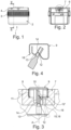
- the contact element 7 includes an electrically insulating receptacle 8, for example made of plastic, in which a spring element 9 is used as an electrical conductor.
- the spring element On the upper side, the spring element has a contact surface 10 for the electrical connection of an adjacent functional element.
- the spring element is supported in the receptacle 8 via two side walls 11 and in a manner that is not shown in detail anchored, for example by means of barbs, locking elements or the like.
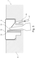
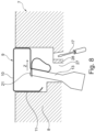
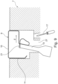
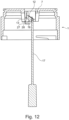
- a slot 16 in the receptacle 8 allows the insertion of a tool 17 shown in phantom, e.g. in the form of a screwdriver, in order to push the cable clamping spring 12 away from the ferrule 13 and thereby release it.
- a tool 17 shown in phantom e.g. in the form of a screwdriver
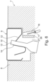
- FIG. 4 shows another embodiment of the spring element 9 of Cable clamping spring 12 with a modified counter bearing 14. Although a ferrule is shown in the illustration to illustrate the oblique direction of insertion here, the cable clamping spring is in the non-deflected position, which corresponds to the position without ferrule.
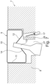
- figure 5 shows the variant of the contact element 7 after Fig.1 , wherein the recording 8 is only partially shown.
- the tool 17 is only indicated and is of course significantly larger in reality.
- ferrules of different cross sections can be used.
- the ferrule shown is significantly narrower than the associated receiving opening 19 in the receptacle 8, so that an inclined insertion position is possible here.
- a ferrule 13 or a wire end of a cable wire with a larger cross-section could also be used.
- the end of the spring element 9 forming the cable clamping spring is shaped in such a way that it forms a clamping cage 19 and a counter bearing 20 .
- the ferrule is inserted through an opening 21 of the terminal cage 19 and clamped between the clamping cage 19 and the counter bearing 20 when springing back in the Z direction.
- the clamping cage can be pressed against the spring direction Z by means of the tool 17 and the jamming of the ferrule 13 can thus be released again.
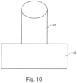
- the spring element 10 shows a special embodiment of the design of the spring element 9.
- the spring element 9 is shown here only partially to illustrate the cross sections.
- the spring element is bent from a wire 21 with a round cross-section and flattened by an embossing 22 in the area of the cable clamping spring.
- a comparable embossing or flattening can also be provided in the area of the contact surface 10 .
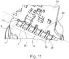
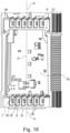
- a printed circuit board 24 is in electrical contact with the contact surfaces 10 of the contact element 7 of the connecting element 1 with end contacts 25.
- the printed circuit board 24 belongs to an adjacent function module, not shown in more detail, which is connected to the connecting element 1 and connected via it.
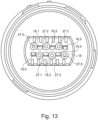
- a signaling column which includes various functional modules 29, 30,31,32,33,34, which can be designed, for example, as light modules, acoustic modules or radio modules.
- the connection element 1 which is not shown in detail in these figures, is designed according to the invention and is used to connect the function modules 29, 30, 31, 32, 33, 34 by means of cable wires, which are not shown. In the cut representation after 15 circuit boards 24 can be seen.
- connection of a function module for example the function module 30 or 31 to 33
- the printed circuit board 35 is provided on the lower end face with end-face contacts 36 in the form of electrically conductive contact surfaces which, as can be seen, run transversely to the longitudinal axis A of the signaling column 28 , the function modules 29 to 34 and the printed circuit board 35 .
- These end-face contacts 36 form counter-contacts to the contact surfaces 10 of the contact springs 18, which are also transverse to the longitudinal axis A, in the contact element 7 of a functional module 31 below or of a connecting element 1 below.
Landscapes
- Engineering & Computer Science (AREA)
- General Engineering & Computer Science (AREA)
- Microelectronics & Electronic Packaging (AREA)
- Coupling Device And Connection With Printed Circuit (AREA)
Applications Claiming Priority (1)
| Application Number | Priority Date | Filing Date | Title |
|---|---|---|---|
| DE102022102441 | 2022-02-02 |
Publications (3)
| Publication Number | Publication Date |
|---|---|
| EP4224634A1 true EP4224634A1 (fr) | 2023-08-09 |
| EP4224634C0 EP4224634C0 (fr) | 2026-03-11 |
| EP4224634B1 EP4224634B1 (fr) | 2026-03-11 |
Family
ID=84688980
Family Applications (1)
| Application Number | Title | Priority Date | Filing Date |
|---|---|---|---|
| EP22217077.1A Active EP4224634B1 (fr) | 2022-02-02 | 2022-12-29 | Système de mise en contact électrique d'un élément de raccordement |
Country Status (5)
| Country | Link |
|---|---|
| US (1) | US20230291133A1 (fr) |
| EP (1) | EP4224634B1 (fr) |
| JP (1) | JP2023113139A (fr) |
| CN (1) | CN116544690A (fr) |
| DE (1) | DE102022134962A1 (fr) |
Families Citing this family (1)
| Publication number | Priority date | Publication date | Assignee | Title |
|---|---|---|---|---|
| DE202023105846U1 (de) * | 2023-10-10 | 2025-01-13 | Zumtobel Lighting Gmbh | Anschlusssystem zur mechanischen und elektrischen Kopplung eines Bauteils an ein Gerät mit integriertem Diebstahl- und Vandalismusschutz |
Citations (7)
| Publication number | Priority date | Publication date | Assignee | Title |
|---|---|---|---|---|
| GB2123614A (en) * | 1982-06-23 | 1984-02-01 | Elektrowatt Ag | Module mounting apparatus |
| DE19614988A1 (de) * | 1996-04-16 | 1997-10-23 | Tridonic Bauelemente | Elektrische Anschlußvorrichtung und elektrisches Verbindungselement zur Verwendung in einer elektrischen Anschlußvorrichtung |
| US6074242A (en) * | 1998-12-31 | 2000-06-13 | Methode Electronics, Inc. | Wire-trap connector for solderless compression connection |
| DE10041202A1 (de) | 2000-08-23 | 2002-03-21 | Lmg Signaltechnologie Kg | Signalsäule |
| EP1467140B1 (fr) | 2003-04-09 | 2007-07-18 | WERMA Signaltechnik GmbH & Co.KG | Dispositif de signalisation |
| WO2012136536A1 (fr) * | 2011-04-08 | 2012-10-11 | Ptr Messtechnik Gmbh & Co. Kommanditgesellschaft | Borne à conducteurs pour deux cartes de circuit imprimé opposées |
| DE102015120280A1 (de) | 2015-11-24 | 2017-05-24 | Werma Holding Gmbh + Co. Kg | Signalgerät mit Leuchtmodul |
-
2022
- 2022-12-29 DE DE102022134962.4A patent/DE102022134962A1/de active Pending
- 2022-12-29 EP EP22217077.1A patent/EP4224634B1/fr active Active
-
2023
- 2023-02-01 JP JP2023014078A patent/JP2023113139A/ja active Pending
- 2023-02-02 US US18/105,193 patent/US20230291133A1/en active Pending
- 2023-02-02 CN CN202310091485.9A patent/CN116544690A/zh active Pending
Patent Citations (7)
| Publication number | Priority date | Publication date | Assignee | Title |
|---|---|---|---|---|
| GB2123614A (en) * | 1982-06-23 | 1984-02-01 | Elektrowatt Ag | Module mounting apparatus |
| DE19614988A1 (de) * | 1996-04-16 | 1997-10-23 | Tridonic Bauelemente | Elektrische Anschlußvorrichtung und elektrisches Verbindungselement zur Verwendung in einer elektrischen Anschlußvorrichtung |
| US6074242A (en) * | 1998-12-31 | 2000-06-13 | Methode Electronics, Inc. | Wire-trap connector for solderless compression connection |
| DE10041202A1 (de) | 2000-08-23 | 2002-03-21 | Lmg Signaltechnologie Kg | Signalsäule |
| EP1467140B1 (fr) | 2003-04-09 | 2007-07-18 | WERMA Signaltechnik GmbH & Co.KG | Dispositif de signalisation |
| WO2012136536A1 (fr) * | 2011-04-08 | 2012-10-11 | Ptr Messtechnik Gmbh & Co. Kommanditgesellschaft | Borne à conducteurs pour deux cartes de circuit imprimé opposées |
| DE102015120280A1 (de) | 2015-11-24 | 2017-05-24 | Werma Holding Gmbh + Co. Kg | Signalgerät mit Leuchtmodul |
Also Published As
| Publication number | Publication date |
|---|---|
| EP4224634C0 (fr) | 2026-03-11 |
| CN116544690A (zh) | 2023-08-04 |
| JP2023113139A (ja) | 2023-08-15 |
| DE102022134962A1 (de) | 2023-08-03 |
| US20230291133A1 (en) | 2023-09-14 |
| EP4224634B1 (fr) | 2026-03-11 |
Similar Documents
| Publication | Publication Date | Title |
|---|---|---|
| DE19813458B4 (de) | Elektrischer Verbinder | |
| DE102007017593B4 (de) | Elektrische Anschluß- und Verbindungsklemme | |
| DE2733934A1 (de) | Schaltungsbauelementen-steckvorrichtung mit bewegbarer traegerteiltrennvorrichtung | |
| DE10145324C2 (de) | Elektrisches Anschlusselement | |
| EP1730816B1 (fr) | Adaptateur enfichable | |
| DE10103107A1 (de) | Anschlußklemme für elektrische Leiter | |
| EP0888228A1 (fr) | Unite de regulation | |
| EP4224634B1 (fr) | Système de mise en contact électrique d'un élément de raccordement | |
| EP0856911A1 (fr) | Bloc de connexion multipolaire | |
| DE102007033942A1 (de) | Elektrische Klemme | |
| EP1154521B1 (fr) | Connecteur et procédé de montage de connecteur | |
| EP1734551A1 (fr) | Dispositif à enfichage pour dispositif électrique de coupure | |
| DE102021106844A1 (de) | System und Kontakteinrichtung mit Fehlsteckschutz | |
| EP4578071A1 (fr) | Câblage de système de connecteur de fiche de commutation et câblage de dispositif | |
| EP3201994A1 (fr) | Barrette à broches | |
| DE102023125917A1 (de) | Steckverbindung mit einem Steckverbinder und einer Steckerbuchse | |
| EP0704942A2 (fr) | Bloc de connexion électrique | |
| EP3625855A1 (fr) | Répartiteur de filerie électrique, dispositif porteur d'un répartiteur de filerie et utilisation d'un connecteur enfichable électrique multipolaire | |
| EP3959780B1 (fr) | Borne de transformateur | |
| EP3949024B1 (fr) | Connecteur enfichable | |
| EP0332866B1 (fr) | Procédé de fabrication d'une prise multiple | |
| EP0822611B1 (fr) | Barette à borne notamment pour des bornes initiateurs/acteurs | |
| DE202018107302U1 (de) | LED-Leiterplattenmodul und Leuchtensystem | |
| DE3022488C2 (fr) | ||
| DE10258725A1 (de) | Steckverbinder für informationstechnische Anschlüsse |
Legal Events
| Date | Code | Title | Description |
|---|---|---|---|
| PUAI | Public reference made under article 153(3) epc to a published international application that has entered the european phase |
Free format text: ORIGINAL CODE: 0009012 |
|
| STAA | Information on the status of an ep patent application or granted ep patent |
Free format text: STATUS: THE APPLICATION HAS BEEN PUBLISHED |
|
| AK | Designated contracting states |
Kind code of ref document: A1 Designated state(s): AL AT BE BG CH CY CZ DE DK EE ES FI FR GB GR HR HU IE IS IT LI LT LU LV MC ME MK MT NL NO PL PT RO RS SE SI SK SM TR |
|
| STAA | Information on the status of an ep patent application or granted ep patent |
Free format text: STATUS: REQUEST FOR EXAMINATION WAS MADE |
|
| 17P | Request for examination filed |
Effective date: 20231102 |
|
| RBV | Designated contracting states (corrected) |
Designated state(s): AL AT BE BG CH CY CZ DE DK EE ES FI FR GB GR HR HU IE IS IT LI LT LU LV MC ME MK MT NL NO PL PT RO RS SE SI SK SM TR |
|
| GRAP | Despatch of communication of intention to grant a patent |
Free format text: ORIGINAL CODE: EPIDOSNIGR1 |
|
| STAA | Information on the status of an ep patent application or granted ep patent |
Free format text: STATUS: GRANT OF PATENT IS INTENDED |
|
| RIC1 | Information provided on ipc code assigned before grant |
Ipc: H01R 4/48 20060101AFI20251126BHEP Ipc: F21V 23/00 20150101ALI20251126BHEP Ipc: F21S 2/00 20160101ALI20251126BHEP Ipc: F21V 23/06 20060101ALI20251126BHEP Ipc: F21Y 115/10 20160101ALI20251126BHEP |
|
| INTG | Intention to grant announced |
Effective date: 20251215 |
|
| GRAS | Grant fee paid |
Free format text: ORIGINAL CODE: EPIDOSNIGR3 |
|
| GRAA | (expected) grant |
Free format text: ORIGINAL CODE: 0009210 |
|
| STAA | Information on the status of an ep patent application or granted ep patent |
Free format text: STATUS: THE PATENT HAS BEEN GRANTED |
|
| AK | Designated contracting states |
Kind code of ref document: B1 Designated state(s): AL AT BE BG CH CY CZ DE DK EE ES FI FR GB GR HR HU IE IS IT LI LT LU LV MC ME MK MT NL NO PL PT RO RS SE SI SK SM TR |
|
| REG | Reference to a national code |
Ref country code: CH Ref legal event code: F10 Free format text: ST27 STATUS EVENT CODE: U-0-0-F10-F00 (AS PROVIDED BY THE NATIONAL OFFICE) Effective date: 20260311 Ref country code: GB Ref legal event code: FG4D Free format text: NOT ENGLISH |
|
| REG | Reference to a national code |
Ref country code: DE Ref legal event code: R096 Ref document number: 502022007314 Country of ref document: DE |
|
| REG | Reference to a national code |
Ref country code: IE Ref legal event code: FG4D Free format text: LANGUAGE OF EP DOCUMENT: GERMAN |
|
| U01 | Request for unitary effect filed |
Effective date: 20260326 |
|
| U07 | Unitary effect registered |
Designated state(s): AT BE BG DE DK EE FI FR IT LT LU LV MT NL PT RO SE SI Effective date: 20260331 |