EP4224720A1 - Dekodierverfahren und -vorrichtung - Google Patents
Dekodierverfahren und -vorrichtung Download PDFInfo
- Publication number
- EP4224720A1 EP4224720A1 EP21885156.6A EP21885156A EP4224720A1 EP 4224720 A1 EP4224720 A1 EP 4224720A1 EP 21885156 A EP21885156 A EP 21885156A EP 4224720 A1 EP4224720 A1 EP 4224720A1
- Authority
- EP
- European Patent Office
- Prior art keywords
- decoding
- code word
- module
- storage module
- engine
- Prior art date
- Legal status (The legal status is an assumption and is not a legal conclusion. Google has not performed a legal analysis and makes no representation as to the accuracy of the status listed.)
- Pending
Links
Images


Classifications
-
- H—ELECTRICITY
- H03—ELECTRONIC CIRCUITRY
- H03M—CODING; DECODING; CODE CONVERSION IN GENERAL
- H03M13/00—Coding, decoding or code conversion, for error detection or error correction; Coding theory basic assumptions; Coding bounds; Error probability evaluation methods; Channel models; Simulation or testing of codes
- H03M13/29—Coding, decoding or code conversion, for error detection or error correction; Coding theory basic assumptions; Coding bounds; Error probability evaluation methods; Channel models; Simulation or testing of codes combining two or more codes or code structures, e.g. product codes, generalised product codes, concatenated codes, inner and outer codes
- H03M13/2906—Coding, decoding or code conversion, for error detection or error correction; Coding theory basic assumptions; Coding bounds; Error probability evaluation methods; Channel models; Simulation or testing of codes combining two or more codes or code structures, e.g. product codes, generalised product codes, concatenated codes, inner and outer codes using block codes
-
- H—ELECTRICITY
- H03—ELECTRONIC CIRCUITRY
- H03M—CODING; DECODING; CODE CONVERSION IN GENERAL
- H03M13/00—Coding, decoding or code conversion, for error detection or error correction; Coding theory basic assumptions; Coding bounds; Error probability evaluation methods; Channel models; Simulation or testing of codes
- H03M13/37—Decoding methods or techniques, not specific to the particular type of coding provided for in groups H03M13/03 - H03M13/35
- H03M13/45—Soft decoding, i.e. using symbol reliability information
-
- H—ELECTRICITY
- H03—ELECTRONIC CIRCUITRY
- H03M—CODING; DECODING; CODE CONVERSION IN GENERAL
- H03M13/00—Coding, decoding or code conversion, for error detection or error correction; Coding theory basic assumptions; Coding bounds; Error probability evaluation methods; Channel models; Simulation or testing of codes
- H03M13/29—Coding, decoding or code conversion, for error detection or error correction; Coding theory basic assumptions; Coding bounds; Error probability evaluation methods; Channel models; Simulation or testing of codes combining two or more codes or code structures, e.g. product codes, generalised product codes, concatenated codes, inner and outer codes
- H03M13/2906—Coding, decoding or code conversion, for error detection or error correction; Coding theory basic assumptions; Coding bounds; Error probability evaluation methods; Channel models; Simulation or testing of codes combining two or more codes or code structures, e.g. product codes, generalised product codes, concatenated codes, inner and outer codes using block codes
- H03M13/2927—Decoding strategies
-
- H—ELECTRICITY
- H03—ELECTRONIC CIRCUITRY
- H03M—CODING; DECODING; CODE CONVERSION IN GENERAL
- H03M13/00—Coding, decoding or code conversion, for error detection or error correction; Coding theory basic assumptions; Coding bounds; Error probability evaluation methods; Channel models; Simulation or testing of codes
- H03M13/29—Coding, decoding or code conversion, for error detection or error correction; Coding theory basic assumptions; Coding bounds; Error probability evaluation methods; Channel models; Simulation or testing of codes combining two or more codes or code structures, e.g. product codes, generalised product codes, concatenated codes, inner and outer codes
- H03M13/2948—Iterative decoding
-
- H—ELECTRICITY
- H03—ELECTRONIC CIRCUITRY
- H03M—CODING; DECODING; CODE CONVERSION IN GENERAL
- H03M13/00—Coding, decoding or code conversion, for error detection or error correction; Coding theory basic assumptions; Coding bounds; Error probability evaluation methods; Channel models; Simulation or testing of codes
- H03M13/37—Decoding methods or techniques, not specific to the particular type of coding provided for in groups H03M13/03 - H03M13/35
- H03M13/3746—Decoding methods or techniques, not specific to the particular type of coding provided for in groups H03M13/03 - H03M13/35 with iterative decoding
-
- H—ELECTRICITY
- H03—ELECTRONIC CIRCUITRY
- H03M—CODING; DECODING; CODE CONVERSION IN GENERAL
- H03M13/00—Coding, decoding or code conversion, for error detection or error correction; Coding theory basic assumptions; Coding bounds; Error probability evaluation methods; Channel models; Simulation or testing of codes
- H03M13/65—Purpose and implementation aspects
- H03M13/6561—Parallelized implementations
-
- H—ELECTRICITY
- H03—ELECTRONIC CIRCUITRY
- H03M—CODING; DECODING; CODE CONVERSION IN GENERAL
- H03M13/00—Coding, decoding or code conversion, for error detection or error correction; Coding theory basic assumptions; Coding bounds; Error probability evaluation methods; Channel models; Simulation or testing of codes
- H03M13/03—Error detection or forward error correction by redundancy in data representation, i.e. code words containing more digits than the source words
- H03M13/05—Error detection or forward error correction by redundancy in data representation, i.e. code words containing more digits than the source words using block codes, i.e. a predetermined number of check bits joined to a predetermined number of information bits
- H03M13/13—Linear codes
- H03M13/15—Cyclic codes, i.e. cyclic shifts of codewords produce other codewords, e.g. codes defined by a generator polynomial, Bose-Chaudhuri-Hocquenghem [BCH] codes
- H03M13/151—Cyclic codes, i.e. cyclic shifts of codewords produce other codewords, e.g. codes defined by a generator polynomial, Bose-Chaudhuri-Hocquenghem [BCH] codes using error location or error correction polynomials
- H03M13/152—Bose-Chaudhuri-Hocquenghem [BCH] codes
Definitions
- This application relates to the field of communication technologies, and in particular, to a decoding method and apparatus.
- FEC forward error correction
- This application provides a decoding method and apparatus, to reduce decoding power consumption.
- this application provides a decoding apparatus.
- the decoding apparatus may be disposed in a receiver of a communication device.
- the communication device may be a terminal device, an access network device, a core network device, or the like.
- the decoding apparatus may include: N sequentially disposed decoding engines, an input bus connected to each of the N decoding engines, and an output bus connected to each of the N decoding engines.
- a j th decoding engine is electrically connected to a (j+1) th decoding engine
- an N th decoding engine is electrically connected to a 1 st decoding engine.
- the input bus is configured to receive a first code word from a channel.
- the (j+1) th decoding engine is configured to: obtain the first code word from the input bus; obtain, from the j th decoding engine and/or the (j+1) th decoding engine, historical data associated with the first code word; and perform N times of iterative decoding on the first code word based on the historical data associated with the first code word.
- the output bus is configured to output an N th decoding result after the N times of iterative decoding is performed on the first code word.
- N ⁇ 2, j ⁇ N-1, and N and j are positive integers.
- the N decoding engines form a ring structure, and the 1 st decoding engine is connected to the N th decoding engine in a head-to-tail manner.
- the N decoding engines may be disposed separately, or may be integrated together.
- each decoding engine includes a storage module
- the decoding engines do not need to share a memory.
- ASIC design congestion caused by a huge Mux and massive connections can be avoided.
- a decoding module in a decoding engine can obtain associated historical data in a storage module of a previous decoding engine, invalid data migration in a decoding process can be fully omitted, thereby reducing memory read/write power consumption in the decoding process.
- the j th decoding engine includes a first decoding module, a first storage module, a first input interface, and a first output interface; and the (j+1) th decoding engine includes a second decoding module, a second storage module, a second input interface, and a second output interface.
- the first decoding module is electrically connected to the first storage module, and the second decoding module is electrically connected to both the first storage module and the second storage module.
- the second input interface is configured to obtain the first code word from the input bus and write the first code word into the second storage module.
- the second decoding module is configured to: periodically obtain a second code word from the second storage module; obtain, from the first storage module and/or the second storage module, historical data associated with the second code word; and perform (i+1) th decoding on the second code word based on the historical data associated with the second code word, and write an (i+1) th decoding result into the second storage module.
- the second output interface is configured to obtain the N th decoding result of the first code word and output the N th decoding result to the output bus.
- the second code word is the first code word or an i th decoding result of the first code word, 1 ⁇ i ⁇ N, and i is a positive integer.
- the first decoding module may include one or more first processors
- the first storage module may be one or more first memories
- the first input interface may be an input circuit, an input module, and input apparatus, or the like
- the first output interface may be an output circuit, an output module, and output apparatus, or the like
- the second decoding module may include one or more second processors
- the second storage module may be one or more second memories
- the second input interface may be an input circuit, an input module, and input apparatus, or the like
- the second output interface may be an output circuit, an output module, and output apparatus, or the like.
- the second code word may include m frames of data.
- the second decoding module is configured to: periodically obtain a k th frame of data in the m frames of data from the second storage module; obtain, from the first storage module and/or the second storage module, historical data associated with the k th frame of data; perform (i+1) th decoding on the k th frame of data based on the historical data associated with the k th frame of data; and update the k th frame of data based on an (i+1) th decoding result.
- k ⁇ m, and m and k are positive integers.
- the second input interface is configured to periodically obtain the first code word from the input bus with a periodicity of N ⁇ m frames.
- the second output interface is configured to output the N th decoding result to the output bus with a periodicity of N ⁇ m frames.
- each frame of data is a multiframe including a plurality of OFEC frames.
- one multiframe may include three OFEC frames.
- the output bus is connected to the first storage module through the first output interface, and the output bus is connected to the second storage module through the second output interface.
- the output bus is connected to the first decoding module through the first output interface, and the output bus is connected to the second decoding module through the second output interface.
- this application provides a decoding method.
- the method may be applied to the decoding apparatus according to the first aspect and any possible implementation of the first aspect.
- the decoding method may include: receiving, by the input bus, a first code word from a channel; obtaining, by the (j+1) th decoding engine, the first code word from the input bus; obtaining, by the (j+1) th decoding engine from the j th decoding engine and/or the (j+1) th decoding engine, historical data associated with the first code word; performing, by the (j+1) th decoding engine, N times of iterative decoding on the first code word based on the historical data associated with the first code word; and outputting, by the output bus, an N th decoding result after the N times of iterative decoding is performed on the first code word.
- N ⁇ 2, j ⁇ N-1, and N and j are positive integers.
- the obtaining, by the (j+1) th decoding engine, the first code word from the input bus may include: obtaining, by the second input interface, the first code word from the input bus, and writing, by the second input interface, the first code word into the second storage module; and periodically obtaining, by the second decoding module, a second code word from the second storage module, where the second code word is the first code word or an i th decoding result of the first code word, 1 ⁇ i ⁇ N, and i is a positive integer.
- the obtaining, by the (j+1) th decoding engine from the j th decoding engine, historical data associated with the first code word includes: obtaining, by the second decoding module from the first storage module and/or the second storage module, historical data associated with the second code word.
- the performing, by the (j+1) th decoding engine, N times of iterative decoding on the second code word based on the historical data associated with the first code word includes: performing, by the second decoding module, (i+1) th decoding on the second code word based on the historical data associated with the second code word, and writing, by the second decoding module, an (i+1) th decoding result into the second storage module; and obtaining, by the second output interface, the N th decoding result after the N times of iterative decoding is performed on the first code word, and outputting, by the second output interface, the N th decoding result to the output bus.
- the second code word includes m frames of data.
- the periodically obtaining, by the second decoding module, a second code word from the second storage module includes: periodically obtaining, by the second decoding module, a k th frame of data in the m frames of data from the second storage module, where k ⁇ m, and m and k are positive integers.
- the obtaining, by the second decoding module from the first storage module and/or the second storage module, historical data associated with the second code word includes: obtaining, by the second decoding module from the first storage module and/or the second storage module, historical data associated with the k th frame of data.
- the writing, by the second decoding module, an (i+1) th decoding result into the second storage module includes: updating, by the second decoding module, the k th frame of data based on the (i+1) th decoding result, until the second decoding module completes (i+1) th decoding of the m frames of data.
- the obtaining, by the second input interface, the first code word from the input bus includes: periodically obtaining, by the second input interface, the first code word from the input bus with a periodicity of N ⁇ m frames.
- the outputting, by the second output interface, the N th decoding result to the output bus includes: outputting, by the second output interface, the N th decoding result to the output bus with a periodicity of N ⁇ m frames.
- each frame of data is a multiframe including a plurality of OFEC frames.
- each multiframe may include three OFEC frames.
- the obtaining, by the second output interface, the N th decoding result includes: obtaining, by the second output interface, the N th decoding result from the second storage module; or obtaining, by the second output interface, the N th decoding result from the second decoding module.
- this application provides a decoding apparatus.
- the decoding apparatus may include a processor and a memory.
- the processor is coupled to the memory.
- the processor is configured to support the decoding apparatus in implementing the decoding method of the decoding module according to the second aspect or any possible implementation of the second aspect.
- this application provides a computer-readable storage medium.
- the computer readable storage medium stores instructions.
- the decoding method of the decoding module according to the second aspect or any possible implementation of the second aspect is performed.
- this application provides a computer program product.
- the computer program product When the computer program product is executed on a computer, the computer implements the decoding method of the decoding module according to the second aspect or any possible implementation of the second aspect.
- indexes such as decoding performance and a delay may be adjusted by configuring different iteration levels.
- different iteration levels also affect implementation complexity and decoding power consumption of the FEC decoder.
- one or more decoding modules are usually encapsulated into a decoding engine (which may be referred to as a processing engine or a decoder engine) for separate implementation design.
- a decoding engine which may be referred to as a processing engine or a decoder engine
- decoding information needs to be transmitted among decoding engines in real time. How to efficiently transmit decoding information among decoding engines is the key in low-power consumption decoding design.
- the iterative decoding may include but is not limited to the following several manners.
- Manner 1 In a multi-level iterative decoding architecture, different iterative decoding levels read/write a same logic memory (denoted as memory below), and data in the memory does not move with iterative decoding.
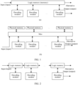
- FIG. 1 is a schematic diagram of an implementation of a decoding apparatus according to an embodiment of this application.
- a plurality of levels of decoding modules share one memory.
- one memory is split into a plurality of specific physical memories, and the physical memories are connected to a plurality of levels of decoding modules by a data multiplexer (multiplexer, Mux).
- Mux data multiplexer
- the huge Mux crosses the plurality of levels of decoding modules, and thousands of connection lines included in the Mux bring a huge congestion risk and a huge power consumption cost to a back-end design of a chip.
- FIG. 2 is a schematic diagram of another implementation of a decoding apparatus according to an embodiment of this application.
- a corresponding logic memory may be separately configured for each level of decoding module.
- decoded data is migrated between different logic memories as a decoding level increases.
- a data block 1 is stored in a memory 1, and a decoding module 1 (decoding module 1) performs first decoding; a data block 2 is stored in a memory 2, and a decoding module 2 performs second decoding; and by analogy, a data block N is stored in a memory N, and a decoding module N performs N th decoding.
- a next time slot of the first time slot for example, a second time slot
- the data block N is outputted after N times of iterative decoding
- a new data block 0 is written into the memory 1
- each of the other data blocks is migrated to a next memory, that is, the data block 1 is migrated to the memory 2
- the data block 2 is migrated to the memory 3, ...
- the data block N-1 is migrated to the memory N.
- first decoding is performed on the data block 0 by the decoding module 1
- second decoding is performed on the data block 1 by the decoding module 2
- third decoding is performed on the data block 2 by the decoding module 3
- N th decoding is performed on the data block N-1 by the decoding module N.
- each data block undergoes N times of iterative decoding in the N decoding modules from input to output, thereby implementing an entire iterative decoding process.
- the data blocks are migrated as a whole among the memories.
- some values do not need to be changed (which may be understood as values that do not need to be migrated), such as an original log-likelihood ratio (likelihood ratio, LLR) inputted from a channel and a posterior probability (a posteriori probability, APP) of a bit that has been correctly decoded in a decoding process.
- LLR log-likelihood ratio
- APP posterior probability
- the decoding apparatus may be disposed in a receiver of a communication device.
- the communication device may be a terminal device, an access network device, a core network device, or the like.
- the terminal device may be a device that provides voice or data connectivity for users, for example, may also be referred to as user equipment (user equipment, UE), a mobile station (mobile station), a subscriber unit (subscriber unit), a station (Station), terminal equipment (terminal equipment, TE), or the like.
- the communication device may be a cellular phone (cellular phone), a personal digital assistant (personal digital assistant, PDA), a wireless modem (modem), a handheld V2P (handheld vehicle to pedestrian) device, a laptop computer (laptop computer), a cordless phone (cordless phone), a wireless local loop (wireless local loop, WLL) station, a tablet computer (pad), or the like.
- cellular phone cellular phone
- PDA personal digital assistant
- modem wireless modem
- handheld V2P handheld vehicle to pedestrian
- laptop computer laptop computer
- cordless phone cordless phone
- WLL wireless local loop
- tablet computer tablet computer
- a device that can access a wireless communication system, communicate with a network side of a wireless communication system, or communicate with another device by using a wireless communication system may be the terminal device in embodiments of this application, such as a terminal in intelligent transportation, a vehicle or a road side unit (road side unit, RSU), a household device in a smart home, a power meter reading instrument in a smart grid, a voltage monitoring instrument, an environment monitoring instrument, a video surveillance instrument in an intelligent security network, or a cash register.
- the terminal device may be fixed or mobile.
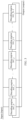
- FIG. 3 is a schematic diagram of a structure of a decoding apparatus according to an embodiment of this application.
- the decoding apparatus 300 provided in this application may include N sequentially disposed decoding engines 301 (for example, including a decoding engine 301_0, a decoding engine 301_1, ..., a decoding engine 301_j, a decoding engine 301_j+1, ..., and a decoding engine 301_N-1), an input bus 302 connected to each of the N decoding engines 301, and an output bus 303 connected to each of the N decoding engines 301.
- N ⁇ 2, j ⁇ N-1, and N and j are positive integers.
- a j th decoding engine (namely, the decoding engine 301_j) is electrically connected to a (j+1) th decoding engine 301_j+1 (namely, the decoding engine 301_j+1), and an N th decoding engine (namely, the decoding engine 301_N-1) is electrically connected to a 1 st decoding engine (namely, the decoding engine 301_1).
- the decoding engine 301J is a previous decoding engine of the decoding engine 301_j+1, the N decoding engines form a ring structure, and the 1 st decoding engine is connected to the N th decoding engine in a head-to-tail manner.
- the input bus 302 is configured to receive a first code word (which may also be understood as a to-be-decoded code word or a new code word) from a channel.
- a first code word (which may also be understood as a to-be-decoded code word or a new code word) from a channel.
- the decoding engine 303_j+1 is configured to: obtain the first code word from the input bus; obtain, from the decoding engine 301_j and/or the decoding engine 301_j+1, historical data associated with the first code word; and perform N times of iterative decoding on the first code word based on the historical data associated with the first code word.
- the output bus 303 is configured to output an N th decoding result after the N times of iterative decoding is performed on the first code word.
- the decoding engine 301_j+1 performs decoding on different data frames in the first code word in different time slots.
- Historical data associated with a first data frame to be decoded is stored in the decoding engine 301_j
- historical data associated with a last data frame to be decoded is stored in the decoding engine 301_j+1.
- One part of historical data associated with other data frames is stored in the decoding engine 301_j, and the other part is stored in the decoding engine 301_j+1.
- the decoding engine 301 may alternatively obtain the first code word from the input bus in another manner. This is not specifically limited in embodiments of this application.
- the N decoding engines may be disposed separately, or may be integrated together.
- each of the N decoding engines may include a decoding module, a storage module, an input interface, and an output interface.
- the input interface obtains the first code word from the input bus, and writes the first code word into the storage module.
- the decoding module periodically (for example, according to a decoding periodicity) obtains a second code word (for example, the first code word or an i th decoding result of the first code word) from the storage module, and obtains historical data associated with the first code word from a storage module in a previous decoding engine and/or the storage module of the decoding engine. Then, the decoding module performs (i+1) th decoding on the second code word based on the historical data associated with the second code word, and writes an (i+1) th decoding result into the storage module. This process is repeated until the decoding module completes N times of iterative decoding on the first code word.
- the output interface obtains an N th decoding result of the first code word, and outputs the N th decoding result to the output bus. 1 ⁇ i ⁇ N, and i is a positive integer.
- the second code word when the decoding module performs first decoding on the first code word, the second code word is the first code word; and when the decoding module performs (i+1) th decoding on the first code word, the second code word is an i th decoding result of the first code word.
- an association relationship between the first code word and the historical data is determined by a coding mode.
- the decoding module may read the historical data associated with the first code word from a storage module of a previous decoding engine; or the decoding engine may read one part of the historical data associated with the first code word from a storage module of a previous decoding engine, and read the other part of the historical data associated with the first code word from the storage module of the decoding engine, so that the historical data associated with the first code word is obtained; or the decoding engine may read the historical data associated with the first code word from the storage module of the decoding engine.
- the historical data may include an original LLR obtained from a channel, extrinsic information generated by a previous decoding engine after decoding, and the like.
- the electrical connection between two decoding engines herein means that a storage module in a previous decoding engine is electrically connected to a decoding module in a next decoding engine.
- the decoding module may be implemented by using one or more processors.
- the storage module may be implemented by using one or more memories.
- the input interface may be an input circuit, an input module, an input apparatus, or the like.
- the output interface may be an output circuit, an output module, an output apparatus, or the like.
- the processor may be implemented by using an application-specific integrated circuit (application-specific integrated circuit, ASIC) or a programmable logic device (programmable logic device, PLD).
- ASIC application-specific integrated circuit
- PLD programmable logic device
- the PLD may be a complex program logic device (complex programmable logic device, CPLD), a field-programmable gate array (FPGA), a generic array logic (generic array logic, GAL) device, or any combination thereof.
- the memory may be a volatile memory or a nonvolatile memory, or may include both a volatile memory and a nonvolatile memory.
- the nonvolatile memory may be a read-only memory (read-only memory, ROM), a programmable read-only memory (programmable ROM, PROM), an erasable programmable read-only memory (erasable PROM, EPROM), an electrically erasable programmable read-only memory (electrically EPROM, EEPROM), or a flash memory.
- the volatile memory may be a random access memory (random access memory, RAM), used as an external cache.
- RAMs may be used, for example, a static random access memory (static RAM, SRAM), a dynamic random access memory (DRAM), a synchronous dynamic random access memory (synchronous DRAM, SDRAM), a double data rate synchronous dynamic random access memory (double data rate SDRAM, DDR SDRAM), an enhanced synchronous dynamic random access memory (enhanced SDRAM, ESDRAM), a synchlink dynamic random access memory (synchlink DRAM, SLDRAM), and a direct rambus random access memory (direct rambus RAM, DR RAM).
- static random access memory static random access memory
- DRAM dynamic random access memory
- SDRAM synchronous dynamic random access memory
- double data rate SDRAM double data rate SDRAM
- DDR SDRAM double data rate SDRAM
- ESDRAM enhanced synchronous dynamic random access memory
- synchlink dynamic random access memory synchlink dynamic random access memory
- SLDRAM direct rambus random access memory
- direct rambus RAM direct rambus RAM
- the decoding module and the storage module may alternatively be implemented in other forms. This is not specifically limited in embodiments of this application.
- FIG. 4 is a schematic diagram of two adjacent decoding engines according to an embodiment of this application (it may be understood that a connection relationship between a storage module and an output interface shown in FIG. 4 is an example implementation).
- the decoding engine 301,j may include a first decoding module 411, a first storage module 412, a first input interface 413, and a first output interface 414; and the decoding engine 301_j+1 includes a second decoding module 421, a second storage module 422, a second input interface 423, and a second output interface 424.
- the first decoding module 411 is electrically connected to the first storage module 412
- the second decoding module 421 is electrically connected to the first storage module 412 and the second storage module 422 respectively.
- the first decoding module may include one or more first processors.
- the first storage module may be one or more first memories.
- the first input interface may be an input circuit, an input module, an input apparatus, or the like.
- the first output interface may be an output circuit, an output module, an output apparatus, or the like.
- the second decoding module may include one or more second processors.
- the second storage module may be one or more second memories.
- the second input interface may be an input circuit, an input module, an input apparatus, or the like.
- the second output interface may be an output circuit, an output module, an output apparatus, or the like.
- the second input interface is configured to: obtain a first code word (denoted as a data block A) from an input bus, and write the first code word into the second storage module.
- the second decoding module is configured to: periodically obtain a second code word (denoted as a data block B, for example, the data block B may be an i th decoding result of the data block A) from the second storage module; obtain, from the first storage module and/or the second storage module, historical data associated with the data block B (it may be understood that the historical data associated with the data block B is also associated with the data block A); and perform (i+1) th decoding on the data block B based on the historical data associated with the data block B, and write an (i+1) th decoding result into the second storage module.
- a second code word denoted as a data block B, for example, the data block B may be an i th decoding result of the data block A
- the second output interface is configured to obtain an N th decoding result of the first code word, and output the N th decoding result to an output bus.
- the second decoding module obtains the data block B (namely, the i th decoding result of the first code word); and reads, from the first storage module and/or the second storage module, the historical data associated with the data block B. Then, the second decoding module performs the (i+1) th decoding on both the historical data associated with the data block B and the data block B, to obtain the (i+1) th decoding result. Next, the second decoding module writes the (i+1) th decoding result into the second storage module, to update the data block B.
- the data block B namely, the i th decoding result of the first code word
- the second decoding module obtains the updated data block B and obtains the historical data associated with the data block B from the first storage module and/or the second storage module; then, the second decoding module performs (i+2) th decoding on both the historical data associated with the data block B and the obtained data block B, to obtain an (i+2) th decoding result; and next, the second decoding module writes the (i+2) th decoding result into the second storage module, to update the data block B.
- the rest may be deduced by analogy until the second decoding module completes N times of decoding on the data block A.
- the decoding engine 301_j+1 in the first time slot, while the decoding engine 301_j+1 is performing (i+1) th decoding, the decoding engine 301_j may perform (i+2) th decoding, the decoding engine 301_j+2 may perform i th decoding, and so on.
- the first code word or the second code word in the foregoing embodiments may include m frames of data.
- the second decoding module may be further configured to: periodically obtain a k th (k ⁇ m, and k is a positive integer) frame of data in the m frames of data from the second storage module; obtain, from the first storage module, historical data associated with the k th frame of data; perform (i+1) th decoding on the k th frame of data based on the historical data associated with the k th frame of data; and update the k th frame of data based on the (i+1) th decoding result.
- the second decoding module When performing the (i+1) th decoding, the second decoding module obtains the k th frame of data (namely, the data block B) in the m frames of data from the second storage module according to a decoding periodicity, and obtains, from the first storage module and/or the second storage module, the historical data associated with the k th frame of data. Then, the second decoding module performs decoding on both the k th frame of data and the historical data associated with the k th frame of data, to obtain the (i+1) th decoding result of the k th frame of data.
- the second decoding module writes the (i+1) th decoding result into the second storage module, to update the k th frame of data, so that the second decoding module may perform (i+2) th decoding by using the updated k th frame of data.
- the second input interface may be configured to periodically obtain the first code word from the input bus with a periodicity of N ⁇ m frames (namely, a decoding periodicity), and write the first code word into the second storage module. Then, the second decoding module reads one frame of data from the second storage module in one time slot, and reads m frames of data in m time slots. This forms a cycle.
- the second output interface may be configured to output an N th decoding result to the output bus with a periodicity of N ⁇ m frames. It may be understood that, in the m time slots, after the m frames of data complete one time of decoding, the m frames of data are rewritten into the second storage module for next decoding, until the m frames of data complete N times of decoding, and the N th decoding result is outputted by the second output interface to the output bus.
- the code word may be an FEC code word, an open forward error correction (open FEC, OFEC) code word, or the like.
- each frame of data may be a multiframe including a plurality of OFEC frames, and parallel decoding may be performed in a time slot.
- connection relationships between the output interface and the storage module in the decoding engine in FIG. 3 and FIG. 4 may have, but are not limited thereto.
- FIG. 5 is a schematic diagram of an output interface and a storage module according to an embodiment of this application.
- an output interface 501 may be disposed between the output bus 303 and a storage module 502, and the storage module 502 is electrically connected to a decoding module 503.
- the decoding module After completing N th decoding on the data block B, the decoding module writes an N th decoding result into the storage module; and then, the output interface obtains the N th decoding result from the storage module, and outputs the N th decoding result to the output bus.
- the decoding module After completing N th decoding on the data block B, the decoding module writes an N th decoding result into the storage module; and then, the output interface obtains the N th decoding result from the storage module, and outputs the N th decoding result to the output bus.
- the output bus may be connected to the first storage module 412 through the first output interface 414; and for the decoding engine 301_j+1, the output bus may also be connected to the second storage module 422 through the second output interface 424.
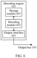
- FIG. 6 is another schematic diagram of an output interface and a storage module according to an embodiment of this application.
- an output interface 601 may be disposed between the output bus 303 and a decoding module 602, and a storage module 603 is electrically connected to the decoding module 602.
- the decoding module 602 After completing N th decoding on the data block B, the decoding module 602 outputs an N th decoding result to the output interface 601, and the N th decoding result is outputted from the output interface 601 to the output bus 303. That is, the decoding module 602 may directly output the N th decoding result.
- the decoding module 602 may further write the N th decoding result into the storage module 603 for use in next decoding.
- the output bus may be connected to the first decoding module 411 through the first output interface 414; and for the decoding engine 301J+1, the output bus may also be connected to the second decoding module 421 through the second output interface 424.
- k 239
- H is a parity-check matrix of an extended BCH (256, 239) code.
- a minimum Hamming (Hocquenghem) distance of the BCH code is 6.
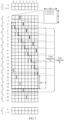
- FIG. 7 is a schematic diagram of a structure of an OFEC code word according to an embodiment of this application (in FIG. 7 , different line types are used to distinguish different constituent code words).
- the structure of the OFEC code word may be shown as follows.
- each bit in the infinite matrix is identified by a 4-tuple ⁇ R, C, r, c ⁇ .
- a constituent code word may be identified by row numbers of all bits that include the other half of the code word.
- (a%b) denotes a value of a modulo b
- (a ⁇ b) denotes a value of bitwise "XOR" of a and b.
- a line segment A indicates a location of the constituent code word (20, 0) in a semi-infinite matrix.
- Bits 0 to 15 are in a column 0 of a block (1, 0)
- bits 16 to 31 are in a column 0 of a block (3, 1)
- ... bits 112 to 127 are in a column 0 of a block (15, 7)
- bits 128 to 255 are in a row 0 of blocks (20, 0) to (20, 7).
- the bits 0 to 127 are referred to as a "front (front)" of the constituent code word
- the bits 128 to 255 are referred to as a "back (back)" of the constituent code word.
- each bit in an OFEC encoder belongs to a "front” of a constituent code word and also belongs to a "back” of another constituent code word. Similarly, if a "back” of a constituent code word is in an odd row of blocks, a "front” of the constituent code word is in an even row of the blocks; or if a "front” of a constituent code word is in an odd row of blocks, a “back” of the constituent code word is in an even row of the blocks.
- guard block a block located below a "front” and above a “back” of a constituent code word is referred to as a guard block.
- a line segment B that identifies a constituent code word (20, 15) (that is, a "back" of the constituent code word (20, 15)) and a line segment A that identifies a constituent code word (20, 0) (that is, a "front” of the constituent code word (20, 0)) are located in the same block.
- "r” is 15 instead of 0, the expressions " ⁇ r” in the formulas (1) and (2) are valid, and bits are fetched in a reverse order in each block. For example, bits 0 to 15 in the "front” of the constituent code word (20, 15) are in the 15th column of a block (1, 0).
- the decoding engine 0, the decoding engine 1, the decoding engine 2, and the decoding engine 3 are electrically connected in sequence, and the decoding engine 3 is electrically connected to the decoding engine 0. It is to be noted that the electrical connection between two decoding engines herein means that a storage module in a previous decoding engine is electrically connected to a decoding module in a next decoding engine.
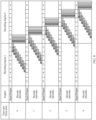
- FIG. 8 is a schematic diagram of a decoding process from a time slot 0 to a time slot 4 according to an embodiment of this application.
- different code words are identified by different hatch patterns.
- Two code words identified by different hatch patterns may form one OFEC frame, and three OFEC frames form one multiframe.
- a decoding engine may decode a data frame or a multiframe.
- the decoding engine 0 performs decoding on a multiframe in a time slot.
- the decoding engine 0 may read multiframes 0 to 4 from an input bus all at once, write the multiframes into a storage module of the decoding engine 0, and then start decoding.
- a decoding module in the decoding engine 0 reads the multiframe 0 (that is, six code words identified by different hatch patterns) from the storage module of the decoding engine 0, and reads historical data associated with the multiframe 0 from a decoding engine 3 (that is, a data block, in the decoding engine 3, identified by the same hatch pattern as the multiframe 0 may also be understood as a "front" of each OFEC code word in the multiframe 0); and then, the decoding module in the decoding engine 0 performs decoding on both the multiframe 0 and the historical data associated with the multiframe 0 to obtain a first decoding result, and writes the first decoding result into the storage module in the decoding engine 0.
- the decoding module in the decoding engine 0 performs decoding on both the multiframe 0 and the historical data associated with the multiframe 0 to obtain a first decoding result, and writes the first decoding result into the storage module in the decoding engine 0.
- the decoding module in the decoding engine 0 reads the multiframe 1 from the storage module of the decoding engine 0, and reads historical data associated with the multiframe 1 from a storage module in the decoding engine 3 and the storage module in the decoding engine 0 (that is, data blocks, in the decoding engine 3 and the decoding engine 0, identified by the same hatch pattern as the multiframe 1 may also be understood as "fronts" of each OFEC code word in the multiframe 1); and then, the decoding module in the decoding engine 0 performs decoding on both the multiframe 1 and the historical data associated with the multiframe 1 to obtain a first decoding result, and writes the first decoding result into the storage module in the decoding engine 0.
- the decoding engine 0 may use a data block associated with the multiframe 1 and obtained from the decoding engine 3 (that is, a data block, in the decoding engine 3, identified by the same hatch pattern as the multiframe 1) and a "front" of the first decoding result of the multiframe 0 obtained from the decoding engine 0 and/or an original LLR obtained from a channel as the historical data associated with the multiframe 1.
- the decoding engine 0 Similar to the time slot 1, in the time slots 2 and 3, the decoding engine 0 reads a multiframe 2 and a multiframe 3 from the input bus in sequence, reading a corresponding multiframe in each time slot, and writes the multiframes into the storage module in the decoding engine 0.
- the decoding module in the decoding engine 0 reads a multiframe (that is, a current multiframe) from the storage module, and reads historical data associated with the current multiframe (that is, a "front" of each OFEC code word in the current multiframe) from the storage module in the decoding engine 3 and the storage module of the decoding engine 0. Then, the decoding module in the decoding engine 0 performs decoding on both the current multiframe and the historical data associated with the current multiframe to obtain a first decoding result, and writes the first decoding result into the storage module in the decoding engine 0.
- the decoding module in the decoding engine 0 reads the multiframe 4 from the storage module in the decoding engine 0, and reads historical data associated with the multiframe 4 (for example, the "fronts" of the first decoding results of the multiframes 0 to 3) from the storage module in the decoding engine 0; and then, the decoding module in the decoding engine 0 performs decoding on both the multiframe 4 and the historical data associated with the multiframe 4 to obtain a first decoding result, and writes the first decoding result into the storage module in the decoding engine 0.
- the decoding module in the decoding engine 0 reads the multiframe 4 from the storage module in the decoding engine 0, and reads historical data associated with the multiframe 4 (for example, the "fronts" of the first decoding results of the multiframes 0 to 3) from the storage module in the decoding engine 0; and then, the decoding module in the decoding engine 0 performs decoding on both the multiframe 4 and the historical data associated with the multiframe 4 to obtain a first decoding result
- the decoding engine 1 reads multiframes 5 to 9 from the input bus, reading a corresponding multiframe in each time slot, and writes the multiframes into a storage module in the decoding engine 1.
- a decoding module in the decoding engine 1 reads a multiframe (that is, a current multiframe) from the storage module, and obtains historical data associated with the current multiframe from the storage module in the decoding engine 0 and/or the decoding engine 1.
- the decoding module in the decoding engine 1 performs decoding on both the current multiframe and the historical data associated with the current multiframe to obtain a first decoding result, and writes the first decoding result into the storage module in the decoding engine 1.
- the decoding engine 0 performs second iterative decoding on the multiframes 0 to 4.
- the decoding engine 2 reads multiframes 10 to 14 from the input bus, reading a corresponding multiframe in each time slot, and writes the multiframes into a storage module in the decoding engine 2.
- a decoding module in the decoding engine 2 reads a multiframe (that is, a current multiframe) from the storage module, and obtains historical data associated with the current multiframe from the storage module in the decoding engine 1 and/or the decoding engine 2. Then, the decoding module in the decoding engine 2 performs decoding on both the current multiframe and the historical data associated with the current multiframe to obtain a first decoding result, and writes the first decoding result into the storage module in the decoding engine 2.
- the decoding engine 0 After decoding is performed on the multiframes 10 to 14, because the multiframes 10 to 14 undergo iterative decoding only once, no output is required. At the same time, the decoding engine 0 performs third iterative decoding on the multiframes 0 to 4, and the decoding engine 1 performs second iterative decoding on the multiframes 5 to 9.
- the decoding engine 3 reads multiframes 15 to 19 from the input bus, reading a corresponding multiframe in each time slot, and writes the multiframes into a storage module in the decoding engine 3.
- a decoding module in the decoding engine 3 reads a multiframe (that is, a current multiframe) from the storage module, and obtains historical data associated with the current multiframe from the storage module in the decoding engine 2 and/or the decoding engine 3. Then, the decoding module in the decoding engine 3 performs decoding on both the current multiframe and the historical data associated with the current multiframe to obtain a first decoding result, and writes the first decoding result into the storage module in the decoding engine 3.
- the decoding engine 0 After decoding is performed on the multiframes 15 to 19, because the multiframes 15 to 19 undergo iterative decoding only once, no output is required.
- the decoding engine 0 performs fourth iterative decoding on the multiframes 0 to 4, the decoding engine 1 performs third iterative decoding on the multiframes 5 to 9, and the decoding engine 2 performs second iterative decoding on the multiframes 10 to 14.
- a fourth decoding result is outputted to an output bus, to release corresponding storage space. Therefore, in a next decoding periodicity, newly received data may be written into the storage module in the decoding engine 0.
- each multiframe fully undergoes four times of iterative decoding from input to output, thereby implementing the entire decoding process.
- each decoding engine includes a storage module
- the decoding engines do not need to share a memory.
- ASIC design congestion caused by a huge Mux and massive connections can be avoided.
- a decoding module in a decoding engine can obtain associated historical data in a storage module of a previous decoding engine, invalid data migration in a decoding process can be fully omitted, thereby reducing memory read/write power consumption in the decoding process.
- embodiments of this application further provide a decoding method.
- the method may be applied to the decoding apparatus in the foregoing embodiments.
- the decoding method in embodiments of this application is described with reference to the structure of the foregoing decoding apparatus.
- FIG. 9 is a schematic flowchart of a decoding method according to an embodiment of this application. As shown in FIG. 9 , the method may include the following steps.
- An input bus receives a first code word from a channel.
- a (j+1) th decoding engine obtains the first code word from the input bus.
- the (j+1) th decoding engine obtains, from a j th decoding engine and/or the (j+1) th decoding engine, historical data associated with the first code word.
- the (j+1) th decoding engine performs N times of iterative decoding on the first code word based on the historical data associated with the first code word.
- An output bus outputs an N th decoding result after the N times of iterative decoding is performed on the first code word.
- N ⁇ 2, j ⁇ N-1, and N and j are positive integers.
- the j th decoding engine includes a first decoding module, a first storage module, a first input interface, and a first output interface; and the (j+1) th decoding engine includes a second decoding module, a second storage module, a second input interface, and a second output interface.
- the first decoding module is electrically connected to the first storage module, and the second decoding module is electrically connected to both the first storage module and the second storage module.
- S902 may include the following steps: The second input interface obtains the first code word from the input bus and writes the first code word into the second storage module; and the second decoding module periodically obtains a second code word from the second storage module, where the second code word is the first code word or an i th decoding result of the first code word, 0 ⁇ i ⁇ N, and i is a positive integer.
- S903 may include the following step: The second decoding module obtains, from the first storage module and/or the second storage module, historical data associated with the second code word.
- S904 may include the following steps: The second decoding module performs (i+1) th decoding on the second code word based on the historical data associated with the second code word, and writes an (i+1) th decoding result into the second storage module; and the second output interface obtains the N th decoding result after the N times of iterative decoding is performed on the first code word, and outputs the N th decoding result to the output bus.
- the first code word may include m frames of data, and m is a positive integer. It may be understood that the second code word may also include m frames of data.
- the step of periodically obtaining a second code word from the second storage module by the second decoding module may include: The second decoding module periodically obtains a k th frame of data in the m frames of data from the second storage module, where k ⁇ m, and k is a positive integer.
- the step of obtaining historical data from the first storage module by the second decoding module may include: The second decoding module obtains, from the first storage module and/or the second storage module, historical data associated with the k th frame of data.
- the step of writing an (i+1) th decoding result into the second storage module by the second decoding module may include: The second decoding module updates the k th frame of data based on the (i+1) th decoding result.
- the step of obtaining the first code word from the input bus by the second input interface in S902 may include: The second input interface periodically obtains the first code word from the input bus with a periodicity of N ⁇ m frames.
- the step of outputting the N th decoding result to the output bus by the second output interface in S904 may include: The second output interface outputs the N th decoding result to the output bus with a periodicity of N ⁇ m frames.
- each frame of data is a multiframe including a plurality of OFEC frames, for example, one multiframe may include three OFEC frames.
- the step of obtaining the N th decoding result by the second output interface in S904 may include: The second output interface obtains the N th decoding result from the second storage module; or the second output interface obtains the N th decoding result from the second decoding module.
Landscapes
- Physics & Mathematics (AREA)
- Probability & Statistics with Applications (AREA)
- Engineering & Computer Science (AREA)
- Theoretical Computer Science (AREA)
- Error Detection And Correction (AREA)
Applications Claiming Priority (2)
| Application Number | Priority Date | Filing Date | Title |
|---|---|---|---|
| CN202011183516.6A CN114430280A (zh) | 2020-10-29 | 2020-10-29 | 一种译码方法及装置 |
| PCT/CN2021/126435 WO2022089429A1 (zh) | 2020-10-29 | 2021-10-26 | 一种译码方法及装置 |
Publications (2)
| Publication Number | Publication Date |
|---|---|
| EP4224720A1 true EP4224720A1 (de) | 2023-08-09 |
| EP4224720A4 EP4224720A4 (de) | 2024-03-27 |
Family
ID=81309157
Family Applications (1)
| Application Number | Title | Priority Date | Filing Date |
|---|---|---|---|
| EP21885156.6A Pending EP4224720A4 (de) | 2020-10-29 | 2021-10-26 | Dekodierverfahren und -vorrichtung |
Country Status (3)
| Country | Link |
|---|---|
| EP (1) | EP4224720A4 (de) |
| CN (1) | CN114430280A (de) |
| WO (1) | WO2022089429A1 (de) |
Families Citing this family (1)
| Publication number | Priority date | Publication date | Assignee | Title |
|---|---|---|---|---|
| CN116610362B (zh) * | 2023-04-27 | 2024-02-23 | 合芯科技(苏州)有限公司 | 一种处理器指令集译码方法、系统、设备和存储介质 |
Family Cites Families (5)
| Publication number | Priority date | Publication date | Assignee | Title |
|---|---|---|---|---|
| WO2009107419A1 (ja) * | 2008-02-26 | 2009-09-03 | 日本電気株式会社 | 復号装置、復号方法及びプログラム |
| EP3242406B1 (de) * | 2015-01-27 | 2020-01-15 | Huawei Technologies Co., Ltd. | Vorrichtung und verfahren zur fec-decodierung |
| US10201026B1 (en) * | 2016-06-30 | 2019-02-05 | Acacia Communications, Inc. | Forward error correction systems and methods |
| US11476949B2 (en) * | 2018-03-29 | 2022-10-18 | Cable Television Laboratories, Inc. | Systems and methods for coherent optics in an access network |
| CN110798231B (zh) * | 2018-08-02 | 2024-01-30 | 北京小米松果电子有限公司 | 咬尾卷积码的译码方法、装置及存储介质 |
-
2020
- 2020-10-29 CN CN202011183516.6A patent/CN114430280A/zh active Pending
-
2021
- 2021-10-26 EP EP21885156.6A patent/EP4224720A4/de active Pending
- 2021-10-26 WO PCT/CN2021/126435 patent/WO2022089429A1/zh not_active Ceased
Also Published As
| Publication number | Publication date |
|---|---|
| CN114430280A (zh) | 2022-05-03 |
| EP4224720A4 (de) | 2024-03-27 |
| WO2022089429A1 (zh) | 2022-05-05 |
Similar Documents
| Publication | Publication Date | Title |
|---|---|---|
| US10432219B2 (en) | Apparatus and method for channel coding in communication system | |
| JP2021064962A (ja) | 情報処理方法および通信装置 | |
| CN101499804B (zh) | 准循环低密度校验码的多码率译码器 | |
| CN109347486B (zh) | 低复杂度高吞吐率的5g ldpc编码器和编码方法 | |
| EP3566316B1 (de) | Verfahren und vorrichtung zur nutzung und erzeugung von vektorbasierter ldpc-basismatrix | |
| CN102882533A (zh) | 基于查找表的dtmb中ldpc串行编码器和编码方法 | |
| CN101777921B (zh) | 用于显式存储片上系统的结构化ldpc码译码方法及装置 | |
| CN109120275B (zh) | 一种编码方法及装置、计算机存储介质 | |
| CN102857324A (zh) | 基于查找表的深空通信中ldpc串行编码器和编码方法 | |
| CN102843147B (zh) | 循环右移累加基的dtmb中ldpc编码器和编码方法 | |
| CN102932007A (zh) | 高度并行的深空通信中qc-ldpc编码器和编码方法 | |
| CN110741559B (zh) | 极化编码器、通信单元、集成电路及其方法 | |
| CN102201817B (zh) | 基于存储器折叠架构优化的低功耗ldpc译码器 | |
| CN109245775B (zh) | 一种译码器及其实现译码的方法 | |
| CN116707546A (zh) | 一种准循环ldpc译码的硬件实现方法及装置 | |
| WO2023125746A1 (zh) | 编码和解码方法、通信设备和存储介质 | |
| CN109889209B (zh) | 一种适用于宇航通信的速率自适应型ldpc译码器 | |
| CN102916706A (zh) | 高度并行的cmmb中qc-ldpc编码器和编码方法 | |
| CN102857239A (zh) | 基于查找表的cmmb中ldpc串行编码器和编码方法 | |
| CN102868495B (zh) | 基于查找表的近地通信中ldpc串行编码器和编码方法 | |
| WO2022089429A1 (zh) | 一种译码方法及装置 | |
| CN110474647B (zh) | 有限域构造的ldpc码的译码方法、装置、译码器及存储介质 | |
| CN100557983C (zh) | 一种准循环低密度奇偶校验码编码器和校验位生成方法 | |
| CN111600613A (zh) | 一种校验方法、装置、译码器、接收机及计算机存储介质 | |
| CN103793197A (zh) | 一种喷泉码编译码方法及装置 |
Legal Events
| Date | Code | Title | Description |
|---|---|---|---|
| STAA | Information on the status of an ep patent application or granted ep patent |
Free format text: STATUS: THE INTERNATIONAL PUBLICATION HAS BEEN MADE |
|
| PUAI | Public reference made under article 153(3) epc to a published international application that has entered the european phase |
Free format text: ORIGINAL CODE: 0009012 |
|
| STAA | Information on the status of an ep patent application or granted ep patent |
Free format text: STATUS: REQUEST FOR EXAMINATION WAS MADE |
|
| 17P | Request for examination filed |
Effective date: 20230505 |
|
| AK | Designated contracting states |
Kind code of ref document: A1 Designated state(s): AL AT BE BG CH CY CZ DE DK EE ES FI FR GB GR HR HU IE IS IT LI LT LU LV MC MK MT NL NO PL PT RO RS SE SI SK SM TR |
|
| DAV | Request for validation of the european patent (deleted) | ||
| DAX | Request for extension of the european patent (deleted) | ||
| REG | Reference to a national code |
Ref country code: DE Ref legal event code: R079 Free format text: PREVIOUS MAIN CLASS: H03M0013450000 Ipc: H03M0013290000 |
|
| A4 | Supplementary search report drawn up and despatched |
Effective date: 20240228 |
|
| RIC1 | Information provided on ipc code assigned before grant |
Ipc: H03M 13/15 20060101ALN20240222BHEP Ipc: H03M 13/00 20060101ALI20240222BHEP Ipc: H03M 13/29 20060101AFI20240222BHEP |
|
| STAA | Information on the status of an ep patent application or granted ep patent |
Free format text: STATUS: EXAMINATION IS IN PROGRESS |
|
| 17Q | First examination report despatched |
Effective date: 20250422 |
|
| GRAP | Despatch of communication of intention to grant a patent |
Free format text: ORIGINAL CODE: EPIDOSNIGR1 |
|
| STAA | Information on the status of an ep patent application or granted ep patent |
Free format text: STATUS: GRANT OF PATENT IS INTENDED |
|
| INTG | Intention to grant announced |
Effective date: 20260305 |