EP4224729A1 - Vorrichtung mit mindestens einem prozessor - Google Patents
Vorrichtung mit mindestens einem prozessor Download PDFInfo
- Publication number
- EP4224729A1 EP4224729A1 EP23152459.6A EP23152459A EP4224729A1 EP 4224729 A1 EP4224729 A1 EP 4224729A1 EP 23152459 A EP23152459 A EP 23152459A EP 4224729 A1 EP4224729 A1 EP 4224729A1
- Authority
- EP
- European Patent Office
- Prior art keywords
- angular
- antenna array
- normalized
- response
- samples
- Prior art date
- Legal status (The legal status is an assumption and is not a legal conclusion. Google has not performed a legal analysis and makes no representation as to the accuracy of the status listed.)
- Pending
Links
Images




Classifications
-
- G—PHYSICS
- G01—MEASURING; TESTING
- G01R—MEASURING ELECTRIC VARIABLES; MEASURING MAGNETIC VARIABLES
- G01R29/00—Arrangements for measuring or indicating electric quantities not covered by groups G01R19/00 - G01R27/00
- G01R29/08—Measuring electromagnetic field characteristics
- G01R29/0864—Measuring electromagnetic field characteristics characterised by constructional or functional features
- G01R29/0892—Details related to signal analysis or treatment; presenting results, e.g. displays; measuring specific signal features other than field strength, e.g. polarisation, field modes, phase, envelope, maximum value
-
- H—ELECTRICITY
- H04—ELECTRIC COMMUNICATION TECHNIQUE
- H04B—TRANSMISSION
- H04B7/00—Radio transmission systems, i.e. using radiation field
- H04B7/02—Diversity systems; Multi-antenna system, i.e. transmission or reception using multiple antennas
- H04B7/04—Diversity systems; Multi-antenna system, i.e. transmission or reception using multiple antennas using two or more spaced independent antennas
- H04B7/0408—Diversity systems; Multi-antenna system, i.e. transmission or reception using multiple antennas using two or more spaced independent antennas using two or more beams, i.e. beam diversity
-
- H—ELECTRICITY
- H04—ELECTRIC COMMUNICATION TECHNIQUE
- H04B—TRANSMISSION
- H04B7/00—Radio transmission systems, i.e. using radiation field
- H04B7/02—Diversity systems; Multi-antenna system, i.e. transmission or reception using multiple antennas
- H04B7/04—Diversity systems; Multi-antenna system, i.e. transmission or reception using multiple antennas using two or more spaced independent antennas
- H04B7/06—Diversity systems; Multi-antenna system, i.e. transmission or reception using multiple antennas using two or more spaced independent antennas at the transmitting station
- H04B7/0613—Diversity systems; Multi-antenna system, i.e. transmission or reception using multiple antennas using two or more spaced independent antennas at the transmitting station using simultaneous transmission
- H04B7/0615—Diversity systems; Multi-antenna system, i.e. transmission or reception using multiple antennas using two or more spaced independent antennas at the transmitting station using simultaneous transmission of weighted versions of same signal
- H04B7/0617—Diversity systems; Multi-antenna system, i.e. transmission or reception using multiple antennas using two or more spaced independent antennas at the transmitting station using simultaneous transmission of weighted versions of same signal for beam forming
-
- G—PHYSICS
- G01—MEASURING; TESTING
- G01S—RADIO DIRECTION-FINDING; RADIO NAVIGATION; DETERMINING DISTANCE OR VELOCITY BY USE OF RADIO WAVES; LOCATING OR PRESENCE-DETECTING BY USE OF THE REFLECTION OR RERADIATION OF RADIO WAVES; ANALOGOUS ARRANGEMENTS USING OTHER WAVES
- G01S3/00—Direction-finders for determining the direction from which infrasonic, sonic, ultrasonic or electromagnetic waves, or particle emission, not having a directional significance, are being received
- G01S3/02—Direction-finders for determining the direction from which infrasonic, sonic, ultrasonic or electromagnetic waves, or particle emission, not having a directional significance, are being received using radio waves
- G01S3/14—Systems for determining direction or deviation from predetermined direction
-
- H—ELECTRICITY
- H04—ELECTRIC COMMUNICATION TECHNIQUE
- H04B—TRANSMISSION
- H04B7/00—Radio transmission systems, i.e. using radiation field
- H04B7/02—Diversity systems; Multi-antenna system, i.e. transmission or reception using multiple antennas
- H04B7/04—Diversity systems; Multi-antenna system, i.e. transmission or reception using multiple antennas using two or more spaced independent antennas
- H04B7/0404—Diversity systems; Multi-antenna system, i.e. transmission or reception using multiple antennas using two or more spaced independent antennas the mobile station comprising multiple antennas, e.g. to provide uplink diversity
-
- H—ELECTRICITY
- H04—ELECTRIC COMMUNICATION TECHNIQUE
- H04B—TRANSMISSION
- H04B7/00—Radio transmission systems, i.e. using radiation field
- H04B7/02—Diversity systems; Multi-antenna system, i.e. transmission or reception using multiple antennas
- H04B7/04—Diversity systems; Multi-antenna system, i.e. transmission or reception using multiple antennas using two or more spaced independent antennas
- H04B7/08—Diversity systems; Multi-antenna system, i.e. transmission or reception using multiple antennas using two or more spaced independent antennas at the receiving station
- H04B7/0837—Diversity systems; Multi-antenna system, i.e. transmission or reception using multiple antennas using two or more spaced independent antennas at the receiving station using pre-detection combining
- H04B7/0842—Weighted combining
- H04B7/086—Weighted combining using weights depending on external parameters, e.g. direction of arrival [DOA], predetermined weights or beamforming
-
- H—ELECTRICITY
- H01—ELECTRIC ELEMENTS
- H01Q—ANTENNAS, i.e. RADIO AERIALS
- H01Q21/00—Antenna arrays or systems
- H01Q21/06—Arrays of individually energised antenna units similarly polarised and spaced apart
Definitions
- Various example embodiments relate to an apparatus comprising at least one processor.
- Wireless communications systems may e.g. be used for wireless exchange of information between two or more entities, e.g. comprising one or more terminal devices, e.g. user equipment, and one or more network devices such as e.g. base stations.
- entities e.g. comprising one or more terminal devices, e.g. user equipment, and one or more network devices such as e.g. base stations.
- the 5th generation of mobile communication drives current communication networks towards physical limits, for example regarding latency, throughput, and spectral efficiency.
- the next (sixth) generation extends networks further, for example by converting communication networks to a joint physical-biological network, wherein, for example, a controller can sense a state and behavior of active and/or passive nodes/devices/objects within its environment.
- mmWave or sub-THz frequencies are also considered to be a candidate for such applications.
- the usage of grid of beams (GoB), analog beamforming and/or hybrid beamforming is preferred to reduce the cost of having a digital chain per antenna element. This requires observing only one or few beams/directions at a time, thus sampling the angular domain.
- Some embodiments relate to an apparatus according to claim 1.
- this enables to efficiently determine a reconstructed angular response, even for antenna arrays with a large number of antenna elements, without sampling the angular response at every possible incoming angle ⁇ for a given scenario.
- it may be particularly beneficial to apply the principle according to the embodiments to antenna array(s) with analog and/or hybrid structures, where for example some antenna elements, for example all antenna elements, are not driven by a (respective "own") digital radio front end.
- the uniform antenna array is a one-dimensional antenna array, for example a uniform linear array (ULA) antenna with a plurality of e.g. N many equally spaced antenna elements.
- ULA uniform linear array
- the uniform antenna array is a two-dimensional antenna array, for example a uniform rectangular array (URA) antenna having a matrix-type arrangement with N many rows and M many columns of antenna elements.
- the antenna elements may be equally spaced along at least one of the two dimensions.
- an inter-element spacing of the antenna elements in a first dimension may be equal to an inter-element spacing of the antenna elements in a second dimension.
- the inter-element spacing of the antenna elements in the first dimension may be different from the inter-element spacing of the antenna elements in the second dimension.
- the angular response of an antenna array may be used to determine an Angle of Departure (AoD) and/or Angle of Arrival (AoA), for example of a strongest path, for example for communication applications, which, according to some embodiments, may for example enable a base station or generally a transmission and/or reception access point, to serve a user with the best radio beam possible.
- AoD Angle of Departure
- AoA Angle of Arrival
- the angular response of an antenna array may be used in sensing applications, for example to reconstruct an image such as a radar image of an environment, e.g. by evaluating directional information as e.g. characterized by the Angle of Departure and/or by the Angle of Arrival (AoA).
- beamforming weights to achieve angular scans can e.g. be designed according to some desired Point Spread Function (PSF), that determines an impact e.g. of an impulsive scatterer at a certain angle with respect to the full image.
- PSF Point Spread Function
- this impact can be related to the resolution (e.g. characterized by a main lobe width) and the side lobes' relative amplitude.
- Some exemplary embodiments which will be discussed in detail further below, provide information regarding a) how many angles and b) which angles should be scanned, e.g. for the uniform sampling of the angular response in the normalized angular frequency range, e.g. for being able to recover, for example without loss, the angular response of the antenna array. Further exemplary embodiments, which will also be discussed in detail further below provide information regarding c) how to reconstruct the angular response at every angle associated with the considered normalized angular frequency range.
- one operates on a one-dimensional (1D) angular dimension corresponding to an incident angle to an orthogonal plane to the 1D array.
- one operates with a two-dimensional (2D) incident angle to the orthogonal axes of the 2D array.
- the instructions when executed by the at least one processor, cause the apparatus to sample the angular response of the uniform antenna array uniformly in a normalized angular frequency range characterized by an interval ⁇ ⁇ 4 d , ⁇ 4 d , wherein ⁇ characterizes a wavelength, wherein d characterizes a distance between adjacent antenna elements.
- the instructions when executed by the at least one processor, cause the apparatus to use N many sampling points for the sampling of the angular response of the uniform antenna array, wherein N characterizes a number of antenna elements of the uniform antenna array.
- a maximum sampling step size for the sampling of the angular response of the uniform antenna array in the normalized angular frequency range is given by ⁇ 2 dN , whereby a loss of information can be avoided.
- avoiding the mentioned loss if information means that the angular response can be perfectly reconstructed, e.g. like if infinite samples were available to probe every possible angle.
- more samples can be taken for the sampling of the angular response, e.g. by sampling with a smaller sampling period, which, in some embodiments may enable to reduce beam misalignment penalties, e.g. with mmWave channel estimation applications.
- the resolution can be reduced and the full angular domain can e.g. be scanned by using less antenna elements, thus increasing the sampling period.
- the extremes of the sampled normalized angular frequency range should be +/- ⁇ 4 d , but in some other embodiments, also +/- 0.5 min 1 ⁇ 2 d , can be considered, where d is the distance between adjacent antenna elements and ⁇ is the wavelength.
- the antennas may be spaced more than ⁇ 2 apart from each other, wherein aliasing may occur in the angular domain, so that, in further embodiments, a search space may be restricted, e.g. to an angular interval of interest with a total normalized angular frequency of ⁇ 2 d ⁇ 1 , thus for example not spanning the whole -90, +90 degree interval.
- the instructions when executed by the at least one processor, cause the apparatus to reconstruct the angular response of the uniform antenna array based on a circular convolution of the set of angular samples and respective Dirichlet kernels. In some embodiments, this may enable a particularly efficient reconstruction of the angular response.
- the set of angular samples is characterized by L N n ⁇ 2 dN , wherein n is an integer, with ⁇ N 2 ⁇ n ⁇ 2, wherein N characterizes a number of antenna elements of the uniform antenna array, wherein ⁇ characterizes a wavelength, wherein d characterizes a distance between adjacent antenna elements, wherein the respective Dirichlet kernels are characterized by D N 2 d ⁇ l ⁇ n ⁇ 2 dN , and wherein the convolution, e.g.
- x n ⁇ N ⁇ 1 2 + n d
- adopting the approach of the exemplary embodiments explained above enables a reconstruction of the angular response for a reduced angular domain, for example in cases where fewer samples are available.
- the approach of the exemplary embodiments explained above may be extended e.g. for sensing applications.
- the set of angular samples as obtained according to exemplary embodiments may be characterized by the aforementioned sampled normalized angular frequency response function L N ′ l .
- available samples L N nB N ⁇ 1 , n ⁇ N N may be up-sampled by the up-sampling factor U, e.g. getting all L N ′ uB NU ⁇ 1 , with u ⁇ N NU .
- the instructions when executed by the at least one processor, cause the apparatus to determine if the number N of antenna elements of the uniform antenna array is even, and, if the number N is even, to double a sequence length associated with the set of angular samples to obtain an extended set of angular samples.
- the instructions when executed by the at least one processor, cause the apparatus to define a sum co-array as a virtual antenna array structure associated with a first antenna array and a second antenna array, and to sample an angular response of the sum co-array uniformly in the normalized angular frequency range to obtain a set of angular samples.
- the first antenna array may at least temporarily operate as a transmitter
- the second antenna array may at least temporarily operate as a receiver.
- a directional transmitter comprising for example a first antenna array, for example a first ULA antenna
- a (directional) receiver comprising for example a second antenna array, for example a second ULA antenna, e.g. orchestrating an operation of the two ULA antennas.
- this does not imply or require a, for example tight, synchronization.
- antenna arrays with comparatively big apertures both at a transmitter and at a receiver.
- antenna arrays may be considered to have the same aperture.
- the sum co-array technique for dimensioning angular scans and/or for reconstruction, for example with analog or hybrid structures, where each antenna element is not driven by a digital radio front end.
- the sum co-array may be characterized by a ULA antenna having (2 N -1) many antenna elements, wherein, in some embodiments, (2 N - 1) many angular samples may be determined by sampling the angular response of the sum co-array uniformly in the normalized angular frequency domain, and wherein, in some embodiments, a reconstruction may be made using Dirichlet kernels of the same order.
- the principle according to the embodiments may also be applied to other antenna arrays than one-dimensional antenna arrays, e.g. to two-dimensional antenna arrays.
- it is proposed to determine two-dimensional angular estimates or samples, e.g. allowing to discriminate both azimuth and elevation.
- a N ⁇ M URA antenna can be seen as a sum co-array of a N elements horizontal ULA antenna and a M elements vertical ULA antenna, whose array lines are orthogonal and define a plane of the URA antenna.
- the instructions when executed by the at least one processor, cause the apparatus to sample an angular response of a uniform two-dimensional antenna array uniformly in respective normalized angular frequency ranges (e.g. being associated with azimuth and elevation, respectively) to obtain a set of angular samples, and to reconstruct an angular response of the uniform two-dimensional antenna array based on the set of angular samples and at least one two-dimensional Dirichlet kernel.
- the scan size can be reduced.
- the instructions when executed by the at least one processor, cause the apparatus to perform a sequential beam scan and/or to scan at least some points in the normalized angular frequency range more than once.
- a response of an environment may change due to, for example, objects moving.
- a phase may quickly rotate, especially at comparatively high carrier frequencies, which may, in some embodiments, generate interference, e.g. when reconstructing an angular response.
- a sequential beam scan in the normalized angular frequency range e.g. to keep consecutively scanned angles also close in time, e.g., scanning angles in an ascending/descending order in the normalized angular frequency range.
- some angles can be scanned multiple times (for example, when sweeping the normalized angular frequency range interval, in some embodiments it is proposed at the end of the sweep to at least partly scan again a beginning of the interval, e.g. to preserve a phase coherence, for example for targets at an end of the normalized angular frequency range interval) .
- Some embodiments relate to an apparatus according to claim 13.
- Some embodiments relate to a method according to claim 14.
- the device may be a base station for a cellular communications network.
- the device may be a mobile device, e.g. a mobile terminal.
- FIG. 1 and 3 relate to an apparatus 100, comprising at least one processor 102, and at least one memory 104 storing instructions 106, the at least one memory 104 and the instructions 106 configured to, with the at least one processor 102, cause the apparatus 100 to sample 200 ( Fig. 3 ) an angular response of a uniform antenna array uniformly in a normalized angular frequency range to obtain a set of angular samples SET-SAMP, and to reconstruct 202 an angular response ANG-RESP of the uniform antenna array based on the set SET-SAMP of angular samples and at least one Dirichlet kernel DIR-KERN.
- an apparatus 100 comprising at least one processor 102, and at least one memory 104 storing instructions 106, the at least one memory 104 and the instructions 106 configured to, with the at least one processor 102, cause the apparatus 100 to sample 200 ( Fig. 3 ) an angular response of a uniform antenna array uniformly in a normalized angular frequency range to obtain a set of
- this enables to efficiently determine a reconstructed angular response, even for antenna arrays with a large number of antenna elements, without sampling the angular response at every possible incoming angle ⁇ for a given scenario.
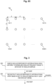
- the uniform antenna array is a one-dimensional antenna array 10a, for example a uniform linear array (ULA) antenna 10a with a plurality of e.g. N many equally spaced antenna elements 12-1, 12-2, 12-3, ..., 12-N, which, in the exemplary depiction of Fig. 2A are arranged a horizontal (array) axis x.
- the spacing between adjacent antenna elements is indicated by reference sign d.
- the vertical axis y in Fig. 2A symbolizes a boresight direction BD of the ULA antenna 10a.
- the antenna elements 12-1, 12-2, ..., 12-8 are positioned at the following absolute positions: -3.5d, -2.5d, ..., 3.5d, corresponding to array aperture line (AAL) positions of ⁇ 7 d ⁇ , ⁇ 5 d ⁇ , ... , 7 d ⁇ .
- the uniform antenna array is a two-dimensional antenna array, for example a uniform rectangular array (URA) antenna 10c having a matrix-type arrangement with N many rows and M many columns of equally spaced antenna elements 12-1-1, ..., 12-1-N, ..., 12-M-1, ..., 12-M-N.
- UAA uniform rectangular array
- the angular response ANG-RESP ( Fig. 3 ) of an antenna array may be used to determine an Angle of Departure (AoD) and/or Angle of Arrival (AoA), for example of a strongest path, for example for communication applications, which, according to some embodiments, may for example enable a base station or generally a transmission and/or reception access point, to serve a user equipment with the best radio beam possible.
- AoD Angle of Departure
- AoA Angle of Arrival
- the angular response ANG-RESP of an antenna array may be used in sensing applications, for example to reconstruct an image such as a radar image of an environment, e.g. by evaluating directional information as e.g. characterized by the Angle of Departure and/or by the Angle of Arrival.
- beamforming weights to achieve angular scans can e.g. be designed according to some desired Point Spread Function (PSF), that determines an impact e.g. of an impulsive scatterer at a certain angle with respect to the full image.
- PSF Point Spread Function
- this impact can be related to the resolution (e.g. characterized by a main lobe width) and the side lobes' relative amplitude.
- Some exemplary embodiments provide information regarding a) how many angles (i.e., corresponding to sample values) and b) which angles should be scanned, e.g. in the course of sampling 200 ( Fig. 3 ), e.g. for the uniform sampling of the angular response in the normalized angular frequency range, e.g. for being able to recover, for example without loss, the angular response ANG-RESP of the antenna array.
- Further exemplary embodiments which will also be discussed in detail further below provide information regarding c) how to reconstruct 202 ( Fig. 3 ) the angular response ANG-RESP at some angles, for example at every angle, associated with the considered normalized angular frequency range.
- the instructions 106 when executed by the at least one processor 102, cause the apparatus 100 to sample 200a the angular response of the uniform antenna array uniformly in a normalized angular frequency range characterized by an interval ⁇ ⁇ 4 d , ⁇ 4 d , wherein ⁇ characterizes a wavelength, wherein d characterizes a distance between adjacent antenna elements.
- the instructions 106 when executed by the at least one processor 102, cause the apparatus 100 to use 200b N many sampling points for the sampling 200, 200a of the angular response of the uniform antenna array, wherein N characterizes a number of antenna elements of the uniform antenna array.
- N characterizes a number of antenna elements of the uniform antenna array.
- another number of sampling points i.e. different from N, may be used for the sampling 200, 200a.
- a maximum sampling step size for the sampling 200, 200a of the angular response of the uniform antenna array in the normalized angular frequency range is given by ⁇ 2 dN , whereby a loss of information can be avoided.
- more samples can be taken for the sampling 200, 200a of the angular response, e.g. by sampling with a smaller sampling period, which, in some embodiments may enable to reduce beam misalignment penalties, e.g. with mmWave channel estimation applications.
- the resolution can be reduced and the full angular domain can e.g. be scanned by using less antenna elements, thus increasing the sampling period.
- the extremes of the sampled normalized angular frequency range are (or should be) + / ⁇ ⁇ 4 d , but in some other embodiments, also + / ⁇ 0.5 min 1 ⁇ 2 d , can be considered, where d is the distance between adjacent antenna elements and ⁇ is the wavelength. In further exemplary embodiments, other values for the extremes of the sampled normalized angular frequency range are possible.
- the instructions 106 when executed by the at least one processor 102, cause the apparatus 100 to reconstruct 202a the angular response ANG-RESP of the uniform antenna array based on a convolution of the set SET-SAMP of angular samples and respective Dirichlet kernels. In some embodiments, this may enable a particularly efficient reconstruction of the angular response ANG-RESP.
- Fig. 12 Dirichlet kernel examples of the type D N 2 d ⁇ l ⁇ ⁇ according to some embodiments are provided as curves C1, C2, C3, depicted over a normalized angular frequency, the Dirichlet kernel examples corresponding to a normalized angular frequency response of a unitary impulsive (in space) scatterer at a normalized angular frequency ⁇ , wherein ULA antennas having different antenna element spacing d and different number N of antenna elements are considered.
- x n ⁇ N ⁇ 1 2 + n d .
- adopting the approach of the exemplary embodiments explained above enables a reconstruction of the angular response for a reduced angular domain, for example in cases where fewer samples are available.
- the approach of the exemplary embodiments explained above may be extended e.g. to sensing applications.
- the set SET-SAMP ( Fig. 3 ) of angular samples as obtained according to exemplary embodiments may be characterized by the aforementioned sampled normalized angular frequency response function L N ′ l .
- available samples L N nB N ⁇ 1 , n ⁇ N N may be up-sampled by the up-sampling factor U, e.g. getting all L N ′ uB NU ⁇ 1 , with u ⁇ N NU .
- the optional block 212 of Fig. 6 exemplarily depicts a use of the up-sampled reconstructed angular response ANG-RESP' as obtained by block 210, e.g. for purposes of communication and/or sensing.
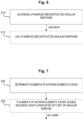
- the instructions 106 when executed by the at least one processor 102, cause the apparatus 100 to determine 220 if the number N of antenna elements of the uniform antenna array is even, and, if the number N is even, to double 222 a sequence length associated with the set SET-SAMP of angular samples to obtain an extended set SET-SAMP' of angular samples.
- the extended set SET-SAMP' of angular samples may be used for reconstruction (not shown in Fig. 7 ), e.g. according to at least one of the approaches explained above, see for example block 202 of Fig. 3 .
- the angular response may e.g. be sampled with a reduced sampling period (e.g. compared to the above-discussed exemplary embodiments with sampling period or step size of ⁇ 2 dN ) in the normalized angular frequency range.
- a Dirichlet Kernel D N of order N is used, however with a normalization factor N / N.
- a certain information loss may be present. In some embodiments, this can e.g. happen due to a resource shortage to transmit a signal in a wireless system, or due to an analog beam codebook having a reduced number of beams that can be stored.
- Option 1 there are two options, denoted as “Option 1" and “Option 2", to exploit the information that can be determined based on the available scans, e.g. to make the best out of the scans available.
- Option 1 If the full non-aliased angular aperture of ⁇ 2 d is not of interest, in some embodiments, it is proposed to focus the available N ' many scans in the directions or angular (sub-) range(s) of interest (e.g., thus not sampling a, for example full, ⁇ ⁇ 4 d , ⁇ 4 d interval), sampling the normalized angular frequency range or domain, respectively, with a period of e.g. ⁇ 2 dN , and then to interpolate, e.g. reconstruct then angular response ANG-RESP ( Fig. 3 ), in the interval of interest.
- this allows to limit the normalized angular frequency range or domain, respectively, e.g. within the [-0.5, 0.5] interval, due to the ⁇ ⁇ 2 , ⁇ 2 limit of the angular domain. In some embodiments, this reduces the number of, for example necessary, scans by approximately a factor of ⁇ 2 d . In some embodiments, minor losses, e.g. in terms of distortion, may result from not probing the full normalized angular frequency domain. However, in some embodiments, this approach according to "Option 1" e.g. allows to preserve a resolution in the direction(s) of interest.
- the full normalized angular frequency domain aliasing period of interest is ⁇ ⁇ 4 d , ⁇ 4 d
- the two approaches characterized by "Option 1" and “Option 2" above can be combined, e.g. in case that a number of scans is not sufficient to scan a reduced angular range.
- a non-aliased interval ⁇ ⁇ 4 d , ⁇ 4 d is smaller than a full (normalized) angular range given by [-0.5, 0.5].
- N to reject aliasing (e.g., instead of sampling the full angular range with the usual sampling period).
- Fig. 8 the instructions 106 ( Fig. 1 ), when executed by the at least one processor 102, cause the apparatus 100 to define 230 ( Fig. 8 ) a sum co-array as a virtual antenna array structure VAA-STRUCT associated with a first antenna array and a second antenna array, and to sample 232 an angular response of the sum co-array uniformly in the normalized angular frequency range to obtain a set SET-SAMP-CO of angular samples.
- the first antenna array may at least temporarily operate as a transmitter, and the second antenna array may at least temporarily operate as a receiver.
- the optional block 234 symbolizes a reconstruction of the angular response ANG-RESP-CO of the sum co-array based on the set SET-SAMP-CO of angular samples and at least one Dirichlet kernel.
- a directional transmitter comprising for example a first antenna array, for example a first ULA antenna
- a (directional) receiver comprising for example a second antenna array, for example a second ULA antenna.
- antenna arrays with comparatively big apertures both at a transmitter and at a receiver.
- antenna arrays may be considered to have the same aperture.
- the sum co-array technique for dimensioning angular scans and/or for reconstruction, for example with analog structures.
- the sum co-array may be characterized by a ULA antenna having (2 N - 1) many antenna elements, wherein, in some embodiments, (2 N - 1) many angular samples may be determined for sampling the angular response of the sum co-array, and wherein, in some embodiments, a reconstruction may be made using Dirichlet kernels of the same order.
- the principle according to the embodiments may also be applied to other antenna arrays than one-dimensional antenna arrays 10a, 10b as exemplarily depicted by Fig. 2A, 2B , e.g. to two-dimensional antenna arrays 10c as exemplarily depicted by Fig. 2C .
- a N ⁇ M URA antenna 10c ( Fig. 2C ) can be seen as a sum co-array of a N elements horizontal ULA antenna and a M elements vertical ULA antenna, whose array lines are orthogonal and define a plane of the URA antenna.
- Fig. 9 the instructions 106 ( Fig. 1 ), when executed by the at least one processor 102, cause the apparatus 100 to sample 240 ( Fig. 9 ) an angular response of a uniform two-dimensional antenna array 10c ( Fig. 2C ) uniformly in respective normalized angular frequency ranges (e.g. being associated with azimuth and elevation, respectively) to obtain a set of angular samples SET-SAMP-2D, and to reconstruct 242 an angular response ANG-RESP-2D of the uniform two-dimensional antenna array 10c based on the set SET-SAMP-2D of angular samples and at least one two-dimensional Dirichlet kernel DIR-KERN-2D.
- a uniform two-dimensional antenna array 10c Fig. 2C
- respective normalized angular frequency ranges e.g. being associated with azimuth and elevation, respectively
- the scan size can be reduced with techniques like the ones exemplarily described above with respect to "aspect 1".
- the instructions 106 when executed by the at least one processor 102, cause the apparatus 100 to perform 250 a sequential beam scan and/or to scan 252 at least some points in the normalized angular frequency range more than once, e.g. for sampling the angular response of a uniform antenna array.
- a response of an environment may change due to, for example, objects moving.
- a phase may quickly rotate, especially at comparatively high carrier frequencies, which may, in some embodiments, generate distortion or interference, e.g. when reconstructing an angular response.
- a sequential beam scan in the normalized angular frequency range e.g. to keep consecutively scanned angles also close in time, e.g., scanning angles in an ascending/descending order in the normalized angular frequency range.
- some angles can be scanned multiple times, see block 252 of Fig. 10 .
- Fig. 11 relate to an apparatus 100' comprising means 102' for sampling 200 ( Fig. 3 ) an angular response of a uniform antenna array uniformly in a normalized angular frequency range to obtain a set SET-SAMP of angular samples, and reconstructing 202 an angular response ANG-RESP of the uniform antenna array based on the set SET-SAMP of angular samples and at least one Dirichlet kernel DIR-KERN.
- the means 102' ( Fig. 11 ) for sampling 200 and for reconstructing 202 may e.g. comprise at least one processor 102 ( Fig. 1 ), and at least one memory 104 storing corresponding instructions 106.
- Fig. 3 relate to a method comprising: sampling 200, by an apparatus 100, an angular response of a uniform antenna array uniformly in a normalized angular frequency range to obtain a set SET-SAMP of angular samples, and reconstructing 202, by the apparatus 100, an angular response ANG-RESP of the uniform antenna array based on the set SET-SAMP of angular samples and at least one Dirichlet kernel DIR-KERN.
- FIG. 1 Further embodiments relate to a computer program and/or to a computer program product comprising instructions 106 ( Fig. 1 ) which, when the program is executed by a computer (e.g. comprising the processor 102), cause the computer to carry out the method according to the embodiments.
- a computer e.g. comprising the processor 102
- Fig. 1 relate to a device 1 for wireless applications such as communications and/or sensing, comprising at least one apparatus 100 (and or at least one apparatus 100', see Fig. 11 ) according to the embodiments.
- the device may be a base state for a cellular communications network.
- the device may be a mobile device, e.g. a mobile terminal.
- the device 1 may comprise at least one antenna array (not shown in Fig. 1 , see for example Fig. 2A, 2B , 2C ), e.g. of the ULA type or of the URA type.
- the principle according to the embodiments enables to to efficiently sample and reconstruct a full angular response, e.g. of analog and/or hybrid uniform antenna arrays, e.g. of the ULA type or of the URA type.
- the angular response as may be determined by the embodiments may e.g. be used for communication applications, such as for, e.g. cellular, communications networks of e.g. the 5G and/or 6G type or of other types, and/or for sensing applications, e.g. radar sensing and/or radar imaging.
- the principle according to the embodiments can be used in 6G networks, e.g. where analog and hybrid beamforming solutions are deployed (for example at frequency ranges of 7-20 GHz, mmWave, and higher frequencies.
- the principle according to the embodiments can be applied in both base stations and sensing (access) points, where 6G networks can e.g. also operate as a radar sensor.
- a performance of aspects of the principle according to the embodiment is assessed with Monte Carlo simulation experiments.
- a single terminal network sensing scenario is considered, with full duplex capabilities. Note that according to further embodiments this is equivalent to a mono-static radar acquisition.
- the antenna array exemplarily considered consists of a horizontal N elements analog ULA with a corresponding sum co-array of 2 N - 1 elements ULA.
- the central frequency is chosen to be 28 GHz, e.g. in line with mmWave operating frequencies and the fact that analog arrays may be used in 28 GHz base stations.
- AWGN additive white Gaussian noise
- impulsive (in space) scatterers are placed in an environment such that their path loss and reflection coefficient is of unitary power. Therefore, in some embodiments, one could assess a performance impact with an equivalent SNR ⁇ N ⁇ 2 .
- the targets are placed randomly at angles in the [- ⁇ ⁇ , ⁇ ⁇ ] interval.
- exemplary findings presented herein according to some embodiments may, in some other embodiments, be extended, e.g. to more general cases of e.g. radio imaging, apart from the fact that performance, like object resolution, are more difficult to measure.
- targets move at a constant speed of v m/s, with a uniform random orientation with respect to the antenna array, generating Doppler shifts in acquisitions taken at different times.
- angles are scanned by steering both transmit and receive beamforming weights at the same angle, that is different at each acquisition.
- a minimum of 2 N - 1 angles are scanned according to exemplary embodiments, it was chosen to select the closest power of two to optimize DFT operations.
- the scanned angles are sampled uniformly in the normalized angular frequency range, but in some embodiments, the performance is also benchmarked against uniform sampling in the angular domain, as may e.g. be done in some conventional mmWave base stations.
- the angular sweep is executed sequentially from the lowest angular value to the highest, with scan period P S .
- the targets' angular location is estimated by first interpolating the angular scan to 512 points, determining its absolute value's maximum and then further refining the estimate by determining the position of a parabola passing through the maximum and its two neighbour points.
- the investigated algorithms for reconstructing the angular response are:
- the default parameters for the performance assessments associated with Fig. 13, 14 , 15 are recapped in the following Table 1.
- the scan period of 8.93 ⁇ s is due to the symbol length in 3GPP numerology in presence of 120 kHz sub-carrier spacing, which is a value that can e.g. be used in some mmWave products operating in the 28 GHz frequency bands.
- Table 1 default simulation parameters in some embodiments Base Station Antennas N 16 Carrier Frequency f c 28 GHz Wavelength ⁇ 10.71 mm Antenna separation d ⁇ /2 Scan period P S 8.93 ⁇ s Target speed v 0 m/s Maximum target's angle ⁇ ⁇ ⁇ 3 rad . 60 deg .
- Fig. 13 exemplarily depicts a Root Mean Squared error (RMSE) of a normalized angular frequency estimation over a noise power in dB.
- curves C4, C8 may outperform some conventional approaches such as associated with curves C6, C7, C10, C11.
- the linear behavior at high SNR values see for example curves C4, C8, can be interpreted as a signal that, probably, the Cramer Rao Lower Bound of the estimator is achieved, but this is still to be confirmed.
- the performance improves.
- the "Cubic" interpolation (with the right amount of samples) approach see curve C6 and C10, delivers an error floor at high SNR.
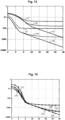
- Figure 14 also depicting RMSE over noise power, shows an impact of speed, e.g. user speed.
- Curve C12 is associated with "Proposal 1"/"CONV” according to some embodiments, for a speed of 0.0 m/s
- curve C13 is associated with the conventional "Cubic” approach, for a speed of 0.0 m/s.
- Curve C14 is associated with "Proposal 1"/"CONV” according to some embodiments, for a speed of 12.0 m/s
- curve C15 is associated with the conventional "Cubic” approach, for a speed of 12.0 m/s.
- Curve C16 is associated with "Proposal 1"/"CONV” according to some embodiments, for a speed of 120.0 m/s
- curve C17 is associated with the conventional "Cubic” approach, for a speed of 120.0 m/s.
- Fig. 14 shows how the proposed mechanism according to exemplary embodiments is more robust, see for example curves C12, C14, until it breaks at extreme target's speeds (120 m/s), see for example curve C16.
- the exemplary results also show the benefits of sampling uniformly in the normalized angular frequency domain according to some embodiments, with further exemplary embodiments defining the best number of scans to be taken.
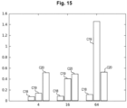
- Figure 15 depicts an average elapsed time in milliseconds (ms) over a number of ULA antenna elements and exemplarily shows the gains in terms of computation time spent with interpolation operations of different approaches.
- the columns C18 are associated with the abovementioned exemplary "Proposal 2"
- the columns C19 are associated with the abovementioned exemplary “Proposal 1”
- the columns C20 are associated with the conventional "Cubic" interpolation approach.
- Column C18 indicates a comparatively small processing time associated with the DFT-based approach "Proposal 2" according to some embodiments
- "Proposal 1" see the columns C19, proposes, according to some embodiments, convolutions in the angular domain.
- the costs of the conventional "Cubic" approach see columns C20, in terms of computational time, are comparatively high, with respect to the approaches C18, C19 according to exemplary embodiments.
- the complexity reduction attained by "Proposal 2" according to some exemplary embodiments can be appreciated, as well as the minor additional complexity involved with more antenna elements, which is, in some embodiments, in line with the O ( N logN ) complexity of DFT operations.
Landscapes
- Engineering & Computer Science (AREA)
- Computer Networks & Wireless Communication (AREA)
- Signal Processing (AREA)
- Physics & Mathematics (AREA)
- General Physics & Mathematics (AREA)
- Electromagnetism (AREA)
- Radar, Positioning & Navigation (AREA)
- Remote Sensing (AREA)
- Variable-Direction Aerials And Aerial Arrays (AREA)
Applications Claiming Priority (1)
| Application Number | Priority Date | Filing Date | Title |
|---|---|---|---|
| FI20225100 | 2022-02-04 |
Publications (1)
| Publication Number | Publication Date |
|---|---|
| EP4224729A1 true EP4224729A1 (de) | 2023-08-09 |
Family
ID=85017529
Family Applications (1)
| Application Number | Title | Priority Date | Filing Date |
|---|---|---|---|
| EP23152459.6A Pending EP4224729A1 (de) | 2022-02-04 | 2023-01-19 | Vorrichtung mit mindestens einem prozessor |
Country Status (3)
| Country | Link |
|---|---|
| US (1) | US12241921B2 (de) |
| EP (1) | EP4224729A1 (de) |
| CN (1) | CN116961714A (de) |
Family Cites Families (4)
| Publication number | Priority date | Publication date | Assignee | Title |
|---|---|---|---|---|
| US9444532B1 (en) | 2015-02-23 | 2016-09-13 | Wisconsin Alumni Research Foundation | Wideband transceiver for antenna array |
| ES2898523T3 (es) | 2016-01-29 | 2022-03-07 | Ericsson Telefon Ab L M | Conformación de haces utilizando una agrupación de antenas |
| KR102693468B1 (ko) | 2017-01-25 | 2024-08-08 | 엘지전자 주식회사 | 하이브리드 빔포밍 시스템에서 최적 빔을 구성하는 방법 및 장치 |
| US11133851B1 (en) * | 2021-03-30 | 2021-09-28 | The Florida International University Board Of Trustees | Beamforming configuration via cross-mixing |
-
2023
- 2023-01-19 EP EP23152459.6A patent/EP4224729A1/de active Pending
- 2023-01-31 US US18/103,769 patent/US12241921B2/en active Active
- 2023-02-03 CN CN202310054537.5A patent/CN116961714A/zh active Pending
Non-Patent Citations (3)
| Title |
|---|
| DAVIS MICHAEL ET AL: "Coherent MIMO radar: The phased array and orthogonal waveforms", IEEE AEROSPACE AND ELECTRONIC SYSTEMS MAGAZINE, IEEE SERVICE CENTER, PISCATAWAY, NJ, US, vol. 29, no. 8, 1 August 2014 (2014-08-01), pages 76 - 91, XP011575592, ISSN: 0885-8985, [retrieved on 20150312], DOI: 10.1109/MAES.2014.130148 * |
| HAMMES CHRISTIAN ET AL: "Generalized Multiplexed Waveform Design Framework for Cost-Optimized MIMO Radar", IEEE TRANSACTIONS ON SIGNAL PROCESSING, IEEE, USA, vol. 69, 27 November 2020 (2020-11-27), pages 88 - 102, XP011827286, ISSN: 1053-587X, [retrieved on 20201224], DOI: 10.1109/TSP.2020.3040859 * |
| WANG CHI-SHIANG ET AL: "Reduced-Complexity Channel Estimation by Hierarchical Interpolation Exploiting Sparsity for Massive MIMO Systems with Uniform Rectangular Array", ICASSP 2021 - 2021 IEEE INTERNATIONAL CONFERENCE ON ACOUSTICS, SPEECH AND SIGNAL PROCESSING (ICASSP), IEEE, 6 June 2021 (2021-06-06), pages 7938 - 7942, XP033955361, DOI: 10.1109/ICASSP39728.2021.9414289 * |
Also Published As
| Publication number | Publication date |
|---|---|
| CN116961714A (zh) | 2023-10-27 |
| US20230251294A1 (en) | 2023-08-10 |
| US12241921B2 (en) | 2025-03-04 |
Similar Documents
| Publication | Publication Date | Title |
|---|---|---|
| CN102857287B (zh) | 宽带波束形成设备,宽带波束导向设备及相应的方法 | |
| KR101603630B1 (ko) | 송신신호 파형의 직교성을 이용한 재머 신호 억제 및 원신호 도래각 추정 방법 및 장치 | |
| US7972271B2 (en) | Apparatus and method for phased subarray imaging | |
| EP3521842A1 (de) | Verfahren und systeme für esa-metrologie | |
| EP2491617B1 (de) | Ein bildgebendes UWB Radar System mit einem zweidimensionalen MIMO Wandlerarray | |
| US20050101867A1 (en) | Apparatus and method for phased subarray imaging | |
| US7273455B2 (en) | Corrections for wavefront aberrations in ultrasound imaging | |
| CN114265058B (zh) | Mimo雷达目标测角方法、装置、电子设备及存储介质 | |
| Zhuge et al. | Sparse multiple-input multiple-output arrays for high-resolution near-field ultra-wideband imaging | |
| JP2019511160A (ja) | 相関扇状ビーム成形機 | |
| CN101609151A (zh) | 一种基于单通道合成孔径雷达(sar)图像序列特征值分解的动目标检测方法 | |
| Mandelli et al. | Sampling and reconstructing angular domains with uniform arrays | |
| Kumari et al. | A combined waveform-beamforming design for millimeter-wave joint communication-radar | |
| CN114895261A (zh) | 基于多频子脉冲编码阵列的杂波抑制方法 | |
| CN113811789A (zh) | 用于评估雷达系统的方法 | |
| EP4224729A1 (de) | Vorrichtung mit mindestens einem prozessor | |
| Nikolov et al. | Analysis and optimization of medical ultrasound imaging using the effective aperture approach | |
| JP4481085B2 (ja) | レーダ装置 | |
| CN118731864B (zh) | 一种空间非均匀采样星载sar方位模糊抑制方法 | |
| Felix et al. | Antenna array design for monostatic ISAC | |
| JPH11183607A (ja) | 合成開口レーダ装置 | |
| Savelyev et al. | Comparison of UWB SAR and MIMO-based short-range imaging radars | |
| El Arja et al. | Joint TOA/DOA measurements for UWB indoor propagation channel using MUSIC algorithm | |
| Constancias et al. | Coherent collocated MIMO radar demonstration for air defence applications | |
| Belfiori et al. | Digital beam forming and compressive sensing based DOA estimation in MIMO arrays |
Legal Events
| Date | Code | Title | Description |
|---|---|---|---|
| PUAI | Public reference made under article 153(3) epc to a published international application that has entered the european phase |
Free format text: ORIGINAL CODE: 0009012 |
|
| STAA | Information on the status of an ep patent application or granted ep patent |
Free format text: STATUS: THE APPLICATION HAS BEEN PUBLISHED |
|
| AK | Designated contracting states |
Kind code of ref document: A1 Designated state(s): AL AT BE BG CH CY CZ DE DK EE ES FI FR GB GR HR HU IE IS IT LI LT LU LV MC ME MK MT NL NO PL PT RO RS SE SI SK SM TR |
|
| STAA | Information on the status of an ep patent application or granted ep patent |
Free format text: STATUS: REQUEST FOR EXAMINATION WAS MADE |
|
| 17P | Request for examination filed |
Effective date: 20240209 |
|
| RBV | Designated contracting states (corrected) |
Designated state(s): AL AT BE BG CH CY CZ DE DK EE ES FI FR GB GR HR HU IE IS IT LI LT LU LV MC ME MK MT NL NO PL PT RO RS SE SI SK SM TR |
|
| STAA | Information on the status of an ep patent application or granted ep patent |
Free format text: STATUS: EXAMINATION IS IN PROGRESS |
|
| 17Q | First examination report despatched |
Effective date: 20250530 |