EP4224992B1 - Procédé de fonctionnement pour un four à arc - Google Patents
Procédé de fonctionnement pour un four à arc Download PDFInfo
- Publication number
- EP4224992B1 EP4224992B1 EP22155430.6A EP22155430A EP4224992B1 EP 4224992 B1 EP4224992 B1 EP 4224992B1 EP 22155430 A EP22155430 A EP 22155430A EP 4224992 B1 EP4224992 B1 EP 4224992B1
- Authority
- EP
- European Patent Office
- Prior art keywords
- control device
- electrodes
- arc furnace
- electric arc
- maximum value
- Prior art date
- Legal status (The legal status is an assumption and is not a legal conclusion. Google has not performed a legal analysis and makes no representation as to the accuracy of the status listed.)
- Active
Links
Images


Classifications
-
- H—ELECTRICITY
- H05—ELECTRIC TECHNIQUES NOT OTHERWISE PROVIDED FOR
- H05B—ELECTRIC HEATING; ELECTRIC LIGHT SOURCES NOT OTHERWISE PROVIDED FOR; CIRCUIT ARRANGEMENTS FOR ELECTRIC LIGHT SOURCES, IN GENERAL
- H05B7/00—Heating by electric discharge
- H05B7/02—Details
- H05B7/144—Power supplies specially adapted for heating by electric discharge; Automatic control of power, e.g. by positioning of electrodes
- H05B7/148—Automatic control of power
-
- F—MECHANICAL ENGINEERING; LIGHTING; HEATING; WEAPONS; BLASTING
- F27—FURNACES; KILNS; OVENS; RETORTS
- F27B—FURNACES, KILNS, OVENS OR RETORTS IN GENERAL; OPEN SINTERING OR LIKE APPARATUS
- F27B3/00—Hearth-type furnaces, e.g. of reverberatory type; Electric arc furnaces ; Tank furnaces
- F27B3/08—Hearth-type furnaces, e.g. of reverberatory type; Electric arc furnaces ; Tank furnaces heated electrically, with or without any other source of heat
- F27B3/085—Arc furnaces
-
- F—MECHANICAL ENGINEERING; LIGHTING; HEATING; WEAPONS; BLASTING
- F27—FURNACES; KILNS; OVENS; RETORTS
- F27B—FURNACES, KILNS, OVENS OR RETORTS IN GENERAL; OPEN SINTERING OR LIKE APPARATUS
- F27B3/00—Hearth-type furnaces, e.g. of reverberatory type; Electric arc furnaces ; Tank furnaces
- F27B3/10—Details, accessories or equipment, e.g. dust-collectors, specially adapted for hearth-type furnaces
- F27B3/28—Arrangement of controlling, monitoring, alarm or the like devices
-
- F—MECHANICAL ENGINEERING; LIGHTING; HEATING; WEAPONS; BLASTING
- F27—FURNACES; KILNS; OVENS; RETORTS
- F27D—DETAILS OR ACCESSORIES OF FURNACES, KILNS, OVENS OR RETORTS, IN SO FAR AS THEY ARE OF KINDS OCCURRING IN MORE THAN ONE KIND OF FURNACE
- F27D19/00—Arrangements of controlling devices
-
- F—MECHANICAL ENGINEERING; LIGHTING; HEATING; WEAPONS; BLASTING
- F27—FURNACES; KILNS; OVENS; RETORTS
- F27D—DETAILS OR ACCESSORIES OF FURNACES, KILNS, OVENS OR RETORTS, IN SO FAR AS THEY ARE OF KINDS OCCURRING IN MORE THAN ONE KIND OF FURNACE
- F27D19/00—Arrangements of controlling devices
- F27D2019/0028—Regulation
- F27D2019/0034—Regulation through control of a heating quantity such as fuel, oxidant or intensity of current
- F27D2019/0037—Quantity of electric current
Definitions
- the present invention is further based on a control program for a control device of an arc furnace, wherein the control program comprises machine code that can be processed by the control device, wherein the processing of the machine code by the control device causes the control device to operate the arc furnace according to such an operating method.
- the present invention further relates to a control device of an arc furnace, wherein the control device is programmed with such a control program, so that the control device operates the arc furnace according to such an operating method.
- the electrical energy is supplied to the electrodes of the arc furnace via a furnace transformer.
- the furnace transformer is often connected to the supply network via a medium-voltage transformer.
- the furnace transformer provides several voltage levels. For the constant power range and other high-current ranges, the respective voltage level can be selected on the furnace transformer. Fine control within a certain voltage level can be achieved, for example, using impedance control.
- the positioning of the electrodes is controlled mechanically, usually via hydraulic adjustment devices.
- the mechanical adjustment of the electrodes is much less dynamic than the actual behavior of the arcs.
- the fluctuations can therefore only be inadequately regulated.
- the fluctuations lead to considerable stress on the components, for example the high-current cables, the current-carrying support arms, the hydraulic cylinders, etc.
- the fluctuations occur both in the melting phase and in a subsequent flat bath phase.
- the positioning of the electrodes must be continuously adjusted.
- the adjustment can be carried out, for example, by regulating to a specific impedance or a specific power.
- the dynamics of the positioning device are relatively low compared to the changes in the electrical system of the arc, certain fluctuations remain that cannot be adjusted. As a result, the energy input into the molten metal is not optimal.
- the electrical energy supply is often carried out with a constant power or constant current.
- the power or current can be maximum, i.e. as high as possible based on the design ("energy supply device, deliver what you can").
- the voltages applied to the electrodes serve to set the desired power or current.
- the electrodes are still quite high up near the lid of the arc furnace, this can lead to the arc forming towards the lid rather than towards the metal as seen from the electrodes. This not only leads to a significantly reduced introduction of energy into the metal, but also to significantly increased wear of the lid, even to the point where damage to the lid occurs after a short time.
- the object of the present invention is to provide possibilities by means of which the disadvantages of the prior art can be avoided.
- an operating method of the type mentioned at the outset is designed in that the control device determines the final voltage target values by limiting the preliminary voltage target values to a permissible maximum value at least during an initial phase of the melting phase, wherein the permissible maximum value is below a possible maximum value that can be applied to the electrodes by the energy supply device.
- the numerical values of 700 V and 1200 V as well as 5000 A are exemplary values that serve as an explanation. In practice, larger or smaller values can also occur. The current in particular can often be considerably larger.
- the maximum permissible value is fixed. In this case, it is possible that the maximum permissible value is only taken into account during the initial phase of the melting phase, but not in a later section of the melting phase. Alternatively, it is possible that the maximum permissible value is taken into account during the entire melting phase, but no longer in the subsequent flat bath phase.
- the permissible maximum value may be dynamic.
- the control device can receive an input value from an operator and for the control device to determine the permissible maximum value depending on the input value.
- the input value can always determine the permissible maximum value, i.e. for an input value of, for example, "500 V" the permissible maximum value is always 500 V.
- the control device can initially determine the permissible maximum value in another way. If the value determined in this way is smaller than the voltage value determined by the input value (for example only 450 V compared to 500 V according to the input value), the value determined by the control device (450 V) is used as the permissible maximum value.
- the value determined by the control device is greater than the voltage value determined by the input value (for example 550 V)
- the voltage value determined by the input value (500 V) is used as the permissible maximum value.
- the numerical values of 450 V, 500 V and 550 V are purely exemplary values that serve as an explanation. In practice, larger or smaller values can also occur.
- a specification according to an input value can alternatively be made continuously or in steps.
- the control device alternatively or in addition to taking the input value into account - to determine the permissible maximum value as a function of a period of time that has elapsed since the start of the melting phase.
- the permissible maximum value can initially have a relatively low value and, after a certain waiting time of, for example, 5 minutes, can be increased in one jump, in several stages or continuously (linearly or non-linearly).
- the permissible maximum value can be increased in later sections, i.e. after at least the initial phase of the melting phase, up to the possible maximum value (and theoretically even beyond that).
- the voltage limitation according to the invention is no longer active from the time at which the possible maximum value is reached.
- the period of 5 minutes mentioned is also only an example. In practice, larger or smaller values can also occur.
- the positioning of the electrodes varies over time.
- the positioning of the electrodes can be known to the control device.
- the control device can also carry out the positioning of the electrodes or the positioning of the electrodes can be supplied to the control device from outside. In one embodiment of the present invention, it is therefore possible for the control device to determine the permissible maximum value depending on the positioning of the electrodes.
- the permissible maximum value can initially have a relatively low value when determining the position of the electrodes and can be increased in one step, in several stages or continuously (linearly or non-linearly) when certain positions are reached, i.e. as a result in later sections of the melting phase.
- the permissible maximum value can be increased up to the possible maximum value and even beyond.
- control device determines a progress of the melting of the metal in the arc furnace by evaluating the temporal progression of two actual electrical variables of the electrical energy supplied to the electrodes and/or by evaluating actual acoustic variables of the arc furnace and to determine the permissible maximum value as a function of the determined progress.
- second electrical actual values serves to distinguish it from the first electrical actual values in a purely formal way. It is intended to express that the electrical actual values on the basis of which the control device determines the progress of the melting of the metal in the arc furnace are not necessarily the same electrical actual values that, if possible, correspond to the electrical target values. This is possible, but not absolutely necessary.
- the first actual electrical quantities can be the electrode currents
- the second actual electrical quantities can be the voltages applied to the electrodes or the power flowing through the electrodes. In individual cases, however, they can also be the same actual electrical quantities.
- the permissible maximum value can initially have a relatively low value when determining the progress determined and can be increased in one step, in several stages or continuously (linearly or non-linearly) when a certain process progress is reached.
- the permissible maximum value can be increased up to the possible maximum value and even beyond.
- control program having the features of claim 6.
- the processing of the machine code by the control device causes the control device to operate the arc furnace according to an operating method according to the invention.
- control device with the features of claim 7.
- the control device is programmed with a control program according to the invention, so that the control device operates the arc furnace according to an operating method according to the invention.
- control device is designed as a control device according to the invention.
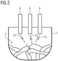
- An arc furnace has a furnace vessel 1.
- the furnace vessel 1 can - see FIG 2 -
- Metal 2 is fed into the furnace vessel 1 in a solid state.
- the metal 2 can be steel, for example, and in the case of steel, in particular scrap.
- the arc furnace also has a power supply device 3.
- the power supply device 3 is connected on the input side to a supply network 4.
- the supply network 4 is usually a medium-voltage network that has a nominal voltage in the 2-digit kV range and is operated with a base frequency f0.
- the base frequency f0 is usually 50 Hz or 60 Hz.
- the supply network 4 is connected as shown in FIG 1 usually a three-phase network.
- the arc furnace also has a furnace transformer 5 and electrodes 6.
- the power supply device 3 is connected on the output side to the electrodes 6 via the furnace transformer 5.
- the furnace transformer 5 is designed as a three-phase transformer.
- other designs are also possible, in particular a single-phase design.
- the electrode voltages U applied to the electrodes 6 are significantly below the nominal voltage of the supply network 4.
- the electrode voltage U is in FIG 1 only shown for one of the electrodes 6.
- the electrode voltages U are usually in the range of several 100 V. In individual cases, voltages above 1 kV are also possible. However, 2 kV is generally not exceeded.
- switching devices are also present, by means of which the energy supply device 3 can be separated from the supply network 4.
- Switching devices can also be present, by means of which the energy supply device 3 can be separated from the furnace transformer 5 and/or the furnace transformer 5 from the electrodes 6.
- the switching devices carry out purely binary switching operations, but do not adjust voltages and currents.
- Active or passive filter devices can also be arranged on the primary or secondary side of the furnace transformer 5. The switching devices and also the filter devices are of secondary importance for the functioning according to the invention and are therefore in FIG 1 (and also the other FIGS) are not shown for the sake of clarity.
- the energy supply device 3 can draw electrical energy from the supply network 4 and supply the drawn electrical energy to the electrodes 6 via the furnace transformer 5.
- the energy supply device 3 usually has many semiconductor switches for this purpose. Possible designs of the energy supply device 3 are shown in the WO 2015/176 899 A1 ("gold standard"). Alternatively, the arrangements according to the EP 3 124 903 A1 or the EP 1 026 921 A1 Regardless of the specific design of the energy supply facility 3, the energy supply device 3 is, however, capable of carrying out a quasi-continuous gradation of the electrode voltages U applied to the electrodes 6 and/or the electrode currents I supplied to the electrodes 6 on the output side - i.e. towards the furnace transformer 5. Analogous to the representation for the electrode voltages U, the electrode current I in FIG 1 also only shown for one of the electrodes 6.
- the electrode voltages U can have a maximum value U0 (see FIGS 5 to 7 ).
- the value U0 - i.e. the possible maximum value of the electrode voltages U - is determined by the nominal voltage of the supply network 4, the design of the energy supply device 3 and the design of the furnace transformer 5.
- the value U0 can be 1200 V.
- the arc furnace has a positioning device 7.
- the electrodes 6 can be positioned as in FIG 1 indicated by a double arrow 8 next to one of the electrodes 6.
- the electrodes 6 are positioned together.
- the electrodes 6 can also be positioned individually.
- the direction of movement in which the electrodes 6 are positioned can be vertical.
- the direction of movement can also be slightly inclined to the vertical. In this case too, however, the component in the vertical direction is the dominant component of the movement.
- the positioning device 7 can, for example, have one or more hydraulic cylinder units.
- the arc furnace has a control device 9. At least the energy supply device 3 is controlled by the control device 9.
- the control device 9 therefore generates control values A1 with which it controls the energy supply device 3. According to the control values A1 operates the energy supply facility 3.
- the positioning device 7 is often also controlled by the control device 9.
- the control device 9 generates further control values A2 with which it controls the positioning device 7.
- the positioning device 7 is operated according to these control values A2.
- the control of the positioning device 7 as such is not the subject of the present invention and is therefore not explained in more detail.
- the control device 9 is designed as a software-programmable control device. This is FIG 1 indicated by the designation " ⁇ P" (for microprocessor-controlled). The effect and mode of operation of the control device 9 is determined by a control program 10 with which the control device 9 is programmed.
- the control program 10 includes machine code 11 that can be processed by the control device 9. The processing of the machine code 11 by the control device 9 causes the control device 9 to operate the arc furnace according to an operating method, as explained in more detail below in connection with the other FIGS.
- the furnace vessel 1 is prepared according to FIG 3 in a step S1 with the metal 2.
- the loading can be carried out under the control of the control device 9. However, it does not have to be carried out under the control of the control device 9.
- the step S1 is therefore in FIG 3 only shown in dashed lines.
- a melting phase of the arc furnace follows. During the melting phase, the metal 2 is melted to form a metal melt 12.
- the melting phase comprises steps S2 to S6.
- the melting phase is followed by a flat bath phase.
- the flat bath phase comprises steps S7 to S11.
- the control device 9 first receives target values X* in step S2.
- the target values X* are electrical values for electrical energy that is to be supplied to the electrodes 6. These can be, for example, electrical target currents or electrical target powers.
- step S3 the control device 9 determines final voltage target values U2*.
- the control device 9 first determines provisional voltage target values U1* based on the electrical target values X* (if necessary, also taking into account first electrical actual values X, which are characteristic of the electrical energy supplied to the electrodes 6).
- the provisional voltage target values U1* are determined in such a way that if voltages U corresponding to the provisional voltage target values U1* were applied to the electrodes 6, the first electrical actual values X would be as close as possible to the corresponding target values X*. An attempt is therefore made, for example, to bring the actual electrical current or the actual electrical power as close as possible to the electrical target current or the electrical target power.
- the provisional voltage target values U1* determined in this way are, however, capped at an upper limit in step S3 to a permissible maximum value Umax.
- the permissible maximum value Umax is (see the FIGS 5 to 7 ) is below the possible maximum value U0. It is usually between 50 % and 75 % of the possible maximum value U0.
- the permissible maximum value Umax can, for example, be between 600 V and 900 V.
- step S4 the control device 9 determines the control values A1 for the energy supply device 3. The determination is made based on the final voltage target values U2*.
- step S5 the control device 9 controls the energy supply device 3 according to the determined control values A1. Due to the corresponding control voltages U corresponding to the final voltage target values U2* are applied to the electrodes 6. As a result, the energy supply device 3 draws electrical energy from the supply network 4 and supplies the electrical energy to the electrodes 6 via the furnace transformer 5. As a result, arcs 13 are formed.
- the control device 9 checks whether a termination condition has been reached.
- the termination condition may be that the melting phase as such has ended.
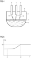
- the melting phase is ended when the metal melt 12 is as shown in FIG 4 has completely or at least essentially formed a continuous horizontal surface.
- the termination condition may consist, for example, in an initial phase being completed within the melting phase, for example a drilling phase. Regardless of the design of the termination condition, the termination condition is generally only met several minutes after the start of the melting phase.
- control device 9 It is possible for the control device 9 to evaluate actual values of the arc furnace that have been measured as part of the check to see whether the termination condition has been reached. For example, it is possible for the control device 9 to evaluate the electrode currents I and/or the electrode voltages U, in particular their fluctuations. The control device 9 can also evaluate acoustic values of the arc furnace, for example the noise level or the acoustic spectrum of the noise generated. Alternatively, it is possible for the control device 9 to be given information by an operator 15 (see FIG 1 ) it is specified that the termination condition has been reached.
- control device 9 If the termination condition has not yet been reached, the control device 9 returns to step S2 (alternatively to step S3). If, however, the termination condition is reached, the control device 9 proceeds to step S7 and thus to a further operating phase of the arc furnace.
- the further operating phase can be, for example, the flat bath phase. Alternatively, the further operating phase can be a later section of the melting phase plus the flat bath phase.
- the control device 9 receives the target values X* in step S7. Furthermore, the control device 9 determines the final voltage target values U2* in step S8. Then, in step S9, the control device 9 determines the control values A1 for the energy supply device 3. In step S10, the control device 9 controls the energy supply device 3 according to the determined control values A1.
- Steps S7 to S10 correspond essentially to steps S2 to S5.
- the only difference is that in step S8 the control device 9 adopts the provisional voltage setpoints U1* directly as the final voltage setpoints U2*, i.e. does not limit the permissible maximum value Umax.
- step S11 the control device 9 checks whether the further operating phase of the arc furnace has ended. In a similar way to the check in step S6, it is possible for the control device 9 to evaluate actual values of the arc furnace that have been measured as part of the check in step S11. Alternatively, it is possible for the operator 15 to inform the control device 9 that the further operating phase has ended.
- step S12 the molten metal 12 produced is removed from the furnace vessel 1, for example poured into a ladle (not shown). The removal of the molten metal 12 can take place under the control of the control device 9. However, it does not have to take place under the control of the control device 9.
- the step S12 is therefore in FIG 3 - analogous to step S1 - only shown in dashed lines.
- step S6 it is also possible to omit steps S6 to S10 and instead return from step S11 to step S2 or step S3.
- the permissible maximum value Umax is taken into account during the entire operation of the arc furnace.
- the permissible maximum value Umax can be set by the control device 9 as shown in FIG 5 as a function of time t.
- a time t1 corresponds to the beginning of the melting phase, i.e. in principle the first ignition of the arcs 13 after charging the furnace vessel 1 with the metal 2.
- the permissible maximum value Umax is usually at its lowest value.
- the permissible maximum value Umax can be increased - as shown in FIG 5 continuously, alternatively in one or more stages - to a higher value. In particular, it can reach the possible maximum value U0 at a time t2.
- control device 9 determines the permissible maximum value Umax in direct dependence on a time period elapsed since the beginning of the melting phase: If the time period elapsed since the beginning of the melting phase is known, the corresponding currently valid permissible maximum value Umax can also be determined.
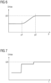
- the permissible maximum value Umax can be set by the control device 9 as shown in FIG 6 as a function of the positioning p of the electrodes 6.
- the representation in FIG 6 is such that the positioning p corresponds to the distance of the undersides of the electrodes 6 from a cover 15 of the furnace vessel 1.
- the permissible maximum value Umax has its lowest value at the smallest positioning p (i.e. at the smallest distance from the cover 15) and increases with increasing distance - as shown in FIG 6 continuously, alternatively in one or more stages - to a higher value.
- the permissible maximum value Umax can be at its lowest value up to a first predetermined positioning p and can reach the possible maximum value U0 at a second predetermined positioning p.
- the control device 9 thus determines the permissible maximum value Umax depending on the positioning p of the electrodes 6.
- the permissible maximum value Umax depends on the time t.
- the associated functional relationship is not known in advance. In particular, it can happen that the positioning p does not increase continuously, but temporarily assumes a smaller value again.
- control device 9 (similar to the procedure in steps S6 and S11) to determine the progress of the melting of the metal 2 in the arc furnace by evaluating the time course of the actual electrical values of the electrical energy supplied to the electrodes 6 and/or by evaluating the actual acoustic values of the arc furnace.
- the control device 9 can in this way determine the transition from the drilling phase to the remaining part of the melting phase and the transition from the Melting phase into the flat bath phase. In this case, the control device 9 can determine the permissible maximum value Umax depending on the determined progress.
- control device 9 can determine the permissible maximum value Umax according to the representation in FIG 7 keep it at a relatively low value during the drilling phase, keep it at a relatively high value (but still below the possible maximum value U0) during the remaining part of the melting phase and ignore it during the shallow bath phase (or alternatively set it equal to the possible maximum value U0 or to a value above the possible maximum value U0).
- control device 9 receives an input value E from the operator 16.
- the control device 9 can determine the permissible maximum value Umax depending on the input value E.
- the input value E can determine the permissible maximum value Umax alone as required or in addition to one of the procedures of the FIGS 5 to 7 be taken into account.
- the present invention has many advantages. In particular, flashovers of the arcs 13 onto the cover 16 of the furnace vessel 1 and the associated disadvantages can be reliably avoided.
Landscapes
- Engineering & Computer Science (AREA)
- Mechanical Engineering (AREA)
- General Engineering & Computer Science (AREA)
- Power Engineering (AREA)
- Physics & Mathematics (AREA)
- Plasma & Fusion (AREA)
- Vertical, Hearth, Or Arc Furnaces (AREA)
- Waste-Gas Treatment And Other Accessory Devices For Furnaces (AREA)
Claims (8)
- Procédé de fonctionnement d'un four à arc, dans lequel pendant une phase de fusion du métal (2) se trouvant dans une cuve de four (1) du four à arc est fondu, dans lequel un dispositif de commande (9) du four à arc- détermine, à l'aide de grandeurs électriques théoriques (X*) d'énergie électrique devant être amenée aux électrodes (6), des valeurs de tension théoriques provisoires (U1*) de sorte que lors de l'application aux électrodes (6) de tensions (U) correspondant aux valeurs de tension théoriques provisoires (U1*), des premières grandeurs électriques réelles (X) d'énergie électrique amenée aux électrodes (6) sont rapprochées autant que possible des grandeurs électriques théoriques (X*), et- commande un dispositif d'alimentation en énergie (3) du four à arc en se basant sur des valeurs de tension théoriques définitives (U2*) de sorte que des tensions (U) correspondant aux valeurs de tension théoriques définitives (U2*) sont appliquées aux électrodes (6) de sorte que le dispositif d'alimentation en énergie (3) se procure de l'énergie électrique à partir d'un réseau d'alimentation (4) et alimente les électrodes (6) au moyen d'un transformateur de four (5),caractérisé en ce que le dispositif de commande (9) détermine, au moins pendant une phase initiale de la phase de fusion, les valeurs de tension théoriques définitives (U2*) en limitant les valeurs de tension théoriques provisoires (U1*) à une valeur maximale admissible (Umax), dans lequel la valeur maximale admissible (Umax) se situe au-dessous d'une valeur maximale possible (U0) qui peut être appliquée aux électrodes (6) par le dispositif d'alimentation en énergie (3).
- Procédé de fonctionnement selon la revendication 1, caractérisé en ce que le dispositif de commande (9) accepte d'un utilisateur (15) une valeur d'entrée (E) et en ce que le dispositif de commande (9) détermine la valeur maximale admissible (Umax) en fonction de la valeur d'entrée (E).
- Procédé de fonctionnement selon la revendication 1 ou 2, caractérisé en ce que le dispositif de commande (9) détermine la valeur maximale admissible (Umax) en fonction d'un laps de temps écoulé depuis le début de la phase de fusion.
- Procédé de fonctionnement selon la revendication 1, 2 ou 3, caractérisé en ce qu'un positionnement (p) des électrodes (6) varie dans le temps, en ce que le positionnement (p) des électrodes (6) est connu du dispositif de commande (9) et en ce que le dispositif de commande (9) détermine la valeur maximale admissible (Umax) en fonction du positionnement (p) des électrodes (6).
- Procédé de fonctionnement selon l'une des revendications précédentes, caractérisé en ce que le dispositif de commande (9) détermine un avancement de la fusion du métal (2) dans le four à arc en évaluant l'évolution dans le temps des deuxièmes grandeurs électriques réelles (U, I) de l'énergie électrique amenée aux électrodes (6) et / ou en évaluant des grandeurs acoustiques réelles du four à arc et en ce que le dispositif de commande (9) détermine la valeur maximale admissible (Umax) en fonction de l'avancement déterminé.
- Programme de commande pour un dispositif de commande (9) d'un four à arc, dans lequel le programme de commande comprend un code machine (11) qui peut être traité par le dispositif de commande (9), caractérisé en ce que le traitement du code machine (11) par le dispositif de commande (9) entraîne que le dispositif de commande (9) actionne le four à arc suivant un procédé de fonctionnement selon l'une des revendications précédentes.
- Dispositif de commande d'un four à arc, caractérisé en ce que le dispositif de commande est programmé avec un programme de commande (10) selon la revendication 6 de sorte que le dispositif de commande actionne le four à arc suivant un procédé de fonctionnement selon l'une des revendications 1 à 5.
- Four à arc,- dans lequel le four à arc présente une cuve de four (1) à laquelle peut être amené du métal (2),- dans lequel le four à arc présente un dispositif d'alimentation en énergie (3) et des électrodes (6) ainsi qu'un transformateur de four (5),- dans lequel le dispositif d'alimentation en énergie (3) est relié du côté de l'entrée à un réseau d'alimentation (4) et du côté de la sortie aux électrodes (6) au moyen du transformateur de four (5),- dans lequel le four à arc présente un dispositif de commande (9) par lequel peut être commandé le dispositif d'alimentation en énergie (3),caractérisé en ce que le dispositif de commande (9) est conçu selon la revendication 7.
Priority Applications (6)
| Application Number | Priority Date | Filing Date | Title |
|---|---|---|---|
| EP22155430.6A EP4224992B1 (fr) | 2022-02-07 | 2022-02-07 | Procédé de fonctionnement pour un four à arc |
| PCT/EP2022/087190 WO2023147931A1 (fr) | 2022-02-07 | 2022-12-21 | Procédé de fonctionnement d'un four à arc électrique |
| US18/834,948 US20250142692A1 (en) | 2022-02-07 | 2022-12-21 | Operating method for an electric arc furnace |
| CN202280091066.9A CN118679853A (zh) | 2022-02-07 | 2022-12-21 | 用于电弧炉的运行方法 |
| JP2024546471A JP7727125B2 (ja) | 2022-02-07 | 2022-12-21 | アーク炉の運転方法 |
| KR1020247029898A KR20240146058A (ko) | 2022-02-07 | 2022-12-21 | 전기 아크 퍼니스에 대한 동작 방법 |
Applications Claiming Priority (1)
| Application Number | Priority Date | Filing Date | Title |
|---|---|---|---|
| EP22155430.6A EP4224992B1 (fr) | 2022-02-07 | 2022-02-07 | Procédé de fonctionnement pour un four à arc |
Publications (3)
| Publication Number | Publication Date |
|---|---|
| EP4224992A1 EP4224992A1 (fr) | 2023-08-09 |
| EP4224992C0 EP4224992C0 (fr) | 2024-11-13 |
| EP4224992B1 true EP4224992B1 (fr) | 2024-11-13 |
Family
ID=80222630
Family Applications (1)
| Application Number | Title | Priority Date | Filing Date |
|---|---|---|---|
| EP22155430.6A Active EP4224992B1 (fr) | 2022-02-07 | 2022-02-07 | Procédé de fonctionnement pour un four à arc |
Country Status (6)
| Country | Link |
|---|---|
| US (1) | US20250142692A1 (fr) |
| EP (1) | EP4224992B1 (fr) |
| JP (1) | JP7727125B2 (fr) |
| KR (1) | KR20240146058A (fr) |
| CN (1) | CN118679853A (fr) |
| WO (1) | WO2023147931A1 (fr) |
Family Cites Families (7)
| Publication number | Priority date | Publication date | Assignee | Title |
|---|---|---|---|---|
| JPH0914864A (ja) * | 1995-06-30 | 1997-01-17 | Toshiba Corp | アーク炉の自動電極昇降制御装置 |
| US5991327A (en) | 1995-10-26 | 1999-11-23 | Inverpower Controls Ltd. | Smart predictive line controller for AC and DC electric arc furnaces |
| JPH09274987A (ja) * | 1996-04-08 | 1997-10-21 | Daido Steel Co Ltd | 溶融炉の電力制御方法 |
| EP2947766A1 (fr) | 2014-05-19 | 2015-11-25 | Siemens Aktiengesellschaft | Alimentation électrique pour une charge non linéaire dotée de convertisseurs matriciels à plusieurs niveaux |
| ITUB20152674A1 (it) | 2015-07-30 | 2017-01-30 | Danieli Automation Spa | Apparato e metodo di alimentazione elettrica di un forno elettrico ad arco |
| IT201800004847A1 (it) * | 2018-04-24 | 2019-10-24 | Metodo di fusione in un forno elettrico ad arco e relativo apparato | |
| JP7539026B2 (ja) * | 2020-03-27 | 2024-08-23 | 大同特殊鋼株式会社 | 交流電気炉の制御方法 |
-
2022
- 2022-02-07 EP EP22155430.6A patent/EP4224992B1/fr active Active
- 2022-12-21 CN CN202280091066.9A patent/CN118679853A/zh active Pending
- 2022-12-21 US US18/834,948 patent/US20250142692A1/en active Pending
- 2022-12-21 KR KR1020247029898A patent/KR20240146058A/ko active Pending
- 2022-12-21 JP JP2024546471A patent/JP7727125B2/ja active Active
- 2022-12-21 WO PCT/EP2022/087190 patent/WO2023147931A1/fr not_active Ceased
Also Published As
| Publication number | Publication date |
|---|---|
| WO2023147931A1 (fr) | 2023-08-10 |
| EP4224992C0 (fr) | 2024-11-13 |
| KR20240146058A (ko) | 2024-10-07 |
| JP7727125B2 (ja) | 2025-08-20 |
| CN118679853A (zh) | 2024-09-20 |
| EP4224992A1 (fr) | 2023-08-09 |
| US20250142692A1 (en) | 2025-05-01 |
| JP2025504185A (ja) | 2025-02-06 |
Similar Documents
| Publication | Publication Date | Title |
|---|---|---|
| EP4360406B1 (fr) | Procédé de fonctionnement pour un four à arc | |
| EP0639880B1 (fr) | Méthode de stabilisation d'un réseau vis à vis des oscillations d'énergie réactive et appareil de compensation d'énergie réactive | |
| EP0369367A1 (fr) | Dispositif et procédé de soudage à l'arc avec court-circuits | |
| EP2850725B1 (fr) | Procédé de régulation d'une source de courant, source de courant et régulateur de processus associés | |
| EP3513625B1 (fr) | Four à arc électrique alimenté par onduleur avec système de condensateurs dans le circuit secondaire | |
| EP0498239A1 (fr) | Procédé et appareil de commande d'une électrode d'un four à arc à courant continu | |
| EP0813284A2 (fr) | Procédé pour la stabilisation d'un réseau de courant alternatif contre les oscillations de la puissance réactive et appareil pour la compensation de la puissance réactive | |
| DE7518767U (de) | Gleichstromlichtbogenofen | |
| DE69824346T2 (de) | Verfahren zur Leistungsregelung von elektrischen Lichtbogenöfen | |
| EP2797197A1 (fr) | Dispositif de commande pour un système de distribution d'énergie et procédé de commande d'un système de distribution d'énergie | |
| DE102006039693A1 (de) | Verfahren zum Betreiben von Windenergieanlagen | |
| DE10221613A1 (de) | Verfahren und Vorrichtung zum martensitfreien Löten | |
| EP4224992A1 (fr) | Procédé de fonctionnement pour un four à arc | |
| EP2843491A1 (fr) | Positionnement avec optimisation de l'énergie et/ou du temps | |
| EP2540138B1 (fr) | Procédé de fonctionnement d'un four à arc, dispositif de commande et/ou de réglage pour un four à arc et four à arc | |
| WO2017085330A1 (fr) | Système d'alimentation en énergie pour four électrique | |
| EP4227624A1 (fr) | Procédé de fonctionnement pour un four à arc | |
| EP4227625A1 (fr) | Procédé de fonctionnement pour un four à arc | |
| EP0571643A1 (fr) | Procédé et dispositif de commande symétrique d'une installation de compensation série | |
| DE102018218439A1 (de) | Leitungssteuerschaltungskonfiguration | |
| EP2529873B1 (fr) | Unité de commande de la force d'un courant d'arc lumineux dans des soudures à impulsions sous gaz de protection ; Procédé de soudage pulsé utilisant un tel contrôle de procédé | |
| DE102004013561B4 (de) | Verfahren und Schaltvorrichtung zum Betreiben einer Zündspule eines Kraftfahrzeugs | |
| EP3753082B1 (fr) | Circuit électrique de compensation de puissance réactive | |
| EP0171617B1 (fr) | Méthode et dispositif pour l'exploitation d'un convertisseur indirect avec limitation de la montée de courant | |
| DE2925054C2 (de) | Stromversorgungseinrichtung für Lichtbogenöfen |
Legal Events
| Date | Code | Title | Description |
|---|---|---|---|
| PUAI | Public reference made under article 153(3) epc to a published international application that has entered the european phase |
Free format text: ORIGINAL CODE: 0009012 |
|
| STAA | Information on the status of an ep patent application or granted ep patent |
Free format text: STATUS: THE APPLICATION HAS BEEN PUBLISHED |
|
| AK | Designated contracting states |
Kind code of ref document: A1 Designated state(s): AL AT BE BG CH CY CZ DE DK EE ES FI FR GB GR HR HU IE IS IT LI LT LU LV MC MK MT NL NO PL PT RO RS SE SI SK SM TR |
|
| STAA | Information on the status of an ep patent application or granted ep patent |
Free format text: STATUS: REQUEST FOR EXAMINATION WAS MADE |
|
| 17P | Request for examination filed |
Effective date: 20240209 |
|
| RBV | Designated contracting states (corrected) |
Designated state(s): AL AT BE BG CH CY CZ DE DK EE ES FI FR GB GR HR HU IE IS IT LI LT LU LV MC MK MT NL NO PL PT RO RS SE SI SK SM TR |
|
| GRAP | Despatch of communication of intention to grant a patent |
Free format text: ORIGINAL CODE: EPIDOSNIGR1 |
|
| STAA | Information on the status of an ep patent application or granted ep patent |
Free format text: STATUS: GRANT OF PATENT IS INTENDED |
|
| INTG | Intention to grant announced |
Effective date: 20240702 |
|
| GRAS | Grant fee paid |
Free format text: ORIGINAL CODE: EPIDOSNIGR3 |
|
| GRAA | (expected) grant |
Free format text: ORIGINAL CODE: 0009210 |
|
| STAA | Information on the status of an ep patent application or granted ep patent |
Free format text: STATUS: THE PATENT HAS BEEN GRANTED |
|
| AK | Designated contracting states |
Kind code of ref document: B1 Designated state(s): AL AT BE BG CH CY CZ DE DK EE ES FI FR GB GR HR HU IE IS IT LI LT LU LV MC MK MT NL NO PL PT RO RS SE SI SK SM TR |
|
| REG | Reference to a national code |
Ref country code: GB Ref legal event code: FG4D Free format text: NOT ENGLISH |
|
| REG | Reference to a national code |
Ref country code: CH Ref legal event code: EP |
|
| REG | Reference to a national code |
Ref country code: DE Ref legal event code: R096 Ref document number: 502022002101 Country of ref document: DE |
|
| REG | Reference to a national code |
Ref country code: IE Ref legal event code: FG4D Free format text: LANGUAGE OF EP DOCUMENT: GERMAN |
|
| U01 | Request for unitary effect filed |
Effective date: 20241113 |
|
| U07 | Unitary effect registered |
Designated state(s): AT BE BG DE DK EE FI FR IT LT LU LV MT NL PT RO SE SI Effective date: 20241118 |
|
| U20 | Renewal fee for the european patent with unitary effect paid |
Year of fee payment: 4 Effective date: 20250228 |
|
| PG25 | Lapsed in a contracting state [announced via postgrant information from national office to epo] |
Ref country code: HR Free format text: LAPSE BECAUSE OF FAILURE TO SUBMIT A TRANSLATION OF THE DESCRIPTION OR TO PAY THE FEE WITHIN THE PRESCRIBED TIME-LIMIT Effective date: 20241113 Ref country code: IS Free format text: LAPSE BECAUSE OF FAILURE TO SUBMIT A TRANSLATION OF THE DESCRIPTION OR TO PAY THE FEE WITHIN THE PRESCRIBED TIME-LIMIT Effective date: 20250313 |
|
| PG25 | Lapsed in a contracting state [announced via postgrant information from national office to epo] |
Ref country code: ES Free format text: LAPSE BECAUSE OF FAILURE TO SUBMIT A TRANSLATION OF THE DESCRIPTION OR TO PAY THE FEE WITHIN THE PRESCRIBED TIME-LIMIT Effective date: 20241113 |
|
| PG25 | Lapsed in a contracting state [announced via postgrant information from national office to epo] |
Ref country code: NO Free format text: LAPSE BECAUSE OF FAILURE TO SUBMIT A TRANSLATION OF THE DESCRIPTION OR TO PAY THE FEE WITHIN THE PRESCRIBED TIME-LIMIT Effective date: 20250213 |
|
| PG25 | Lapsed in a contracting state [announced via postgrant information from national office to epo] |
Ref country code: GR Free format text: LAPSE BECAUSE OF FAILURE TO SUBMIT A TRANSLATION OF THE DESCRIPTION OR TO PAY THE FEE WITHIN THE PRESCRIBED TIME-LIMIT Effective date: 20250214 |
|
| PG25 | Lapsed in a contracting state [announced via postgrant information from national office to epo] |
Ref country code: PL Free format text: LAPSE BECAUSE OF FAILURE TO SUBMIT A TRANSLATION OF THE DESCRIPTION OR TO PAY THE FEE WITHIN THE PRESCRIBED TIME-LIMIT Effective date: 20241113 |
|
| PG25 | Lapsed in a contracting state [announced via postgrant information from national office to epo] |
Ref country code: RS Free format text: LAPSE BECAUSE OF FAILURE TO SUBMIT A TRANSLATION OF THE DESCRIPTION OR TO PAY THE FEE WITHIN THE PRESCRIBED TIME-LIMIT Effective date: 20250213 |
|
| PG25 | Lapsed in a contracting state [announced via postgrant information from national office to epo] |
Ref country code: SM Free format text: LAPSE BECAUSE OF FAILURE TO SUBMIT A TRANSLATION OF THE DESCRIPTION OR TO PAY THE FEE WITHIN THE PRESCRIBED TIME-LIMIT Effective date: 20241113 |
|
| PG25 | Lapsed in a contracting state [announced via postgrant information from national office to epo] |
Ref country code: SK Free format text: LAPSE BECAUSE OF FAILURE TO SUBMIT A TRANSLATION OF THE DESCRIPTION OR TO PAY THE FEE WITHIN THE PRESCRIBED TIME-LIMIT Effective date: 20241113 |
|
| PG25 | Lapsed in a contracting state [announced via postgrant information from national office to epo] |
Ref country code: CZ Free format text: LAPSE BECAUSE OF FAILURE TO SUBMIT A TRANSLATION OF THE DESCRIPTION OR TO PAY THE FEE WITHIN THE PRESCRIBED TIME-LIMIT Effective date: 20241113 |
|
| PG25 | Lapsed in a contracting state [announced via postgrant information from national office to epo] |
Ref country code: MC Free format text: LAPSE BECAUSE OF FAILURE TO SUBMIT A TRANSLATION OF THE DESCRIPTION OR TO PAY THE FEE WITHIN THE PRESCRIBED TIME-LIMIT Effective date: 20241113 |
|
| PLBE | No opposition filed within time limit |
Free format text: ORIGINAL CODE: 0009261 |
|
| STAA | Information on the status of an ep patent application or granted ep patent |
Free format text: STATUS: NO OPPOSITION FILED WITHIN TIME LIMIT |
|
| REG | Reference to a national code |
Ref country code: CH Ref legal event code: PL |
|
| PG25 | Lapsed in a contracting state [announced via postgrant information from national office to epo] |
Ref country code: CH Free format text: LAPSE BECAUSE OF NON-PAYMENT OF DUE FEES Effective date: 20250228 |
|
| 26N | No opposition filed |
Effective date: 20250814 |
|
| PG25 | Lapsed in a contracting state [announced via postgrant information from national office to epo] |
Ref country code: IE Free format text: LAPSE BECAUSE OF NON-PAYMENT OF DUE FEES Effective date: 20250207 |
|
| U20 | Renewal fee for the european patent with unitary effect paid |
Year of fee payment: 5 Effective date: 20260302 |